Article 200
Use and Identification of Grounded Conductors
200.1 Scope.
This article provides requirements for the following:
- Identification of terminals
- Grounded conductors in premises wiring systems
- Identification of grounded conductors
Informational Note: See Article 100 for definitions of Grounded Conductor, Equipment Grounding Conductor, and Grounding Electrode Conductor.
200.2 General.
(A) Insulation.
The grounded conductor, if insulated, shall have insulation that complies with either one of the following:
- Is suitably rated, other than color, for any ungrounded conductor of the same circuit for systems of 1000 volts or less.
- Is rated not less than 600 volts for solidly grounded neutral systems of over 1000 volts in accordance with 250.184(A)
(B) Continuity.
The continuity of a grounded conductor shall not depend on a connection to a metal enclosure, raceway, or cable armor.
Informational Note: See 300.13(B) for the continuity of grounded conductors used in multiwire branch circuits.
200.3 Connection to Grounded System.
Grounded conductors of premises wiring systems shall be electrically connected to the supply system grounded conductor to ensure a common, continuous grounded system. For the purpose of this section, electrically connected shall mean making a direct electrical connection capable of carrying current, as distinguished from induced currents.
Exception: Listed interactive inverters identified for use in distributed resource generation systems such as photovoltaic and fuel cell power systems shall be permitted to be connected to premises wiring without a grounded conductor if the connected premises wiring or utility system includes a grounded conductor.
200.4 Neutral Conductors.
(A) Installation.
Neutral conductors shall not be used for more than one branch circuit, for more than one multiwire branch circuit, or for more than one set of ungrounded feeder conductors unless specifically permitted elsewhere in this Code.
Informational Note: See 215.4 for information on common neutrals.
(B) Multiple Circuits.
Where more than one neutral conductor associated with different circuits is in an enclosure, grounded circuit conductors of each circuit shall be identified or grouped to correspond with the ungrounded circuit conductor(s) by wire markers, cable ties, or similar means in at least one location within the enclosure.
Exception No. 1: The requirement for grouping or identifying shall not apply if the branch-circuit or feeder conductors enter from a cable or a raceway unique to the circuit that makes the grouping obvious.
Exception No. 2: The requirement for grouping or identifying shall not apply where branch-circuit conductors pass through a box or conduit body without a loop as described in 314.16(B)(1) or without a splice or termination.
200.6 Means of Identifying Grounded Conductors.
(A) Sizes 6 AWG or Smaller.
The insulation of grounded conductors of 6 AWG or smaller shall be identified by one of the following means:
- A continuous white outer finish.
- A continuous gray outer finish.
- Three continuous white or gray stripes along the conductor's entire length on other than green insulation.
- Conductors with white or gray insulation and colored tracer threads in the braid identifying the source of manufacture.
- A single-conductor, sunlight-resistant, outdoor-rated cable used as a solidly grounded conductor in photovoltaic power systems, as permitted by 690.31(C)(1), shall be identified at the time of installation by markings at terminations in accordance with 200.6(A)(1) through (A)(4).
- The grounded conductor of a mineral-insulated, metal-sheathed cable (Type MI) shall be identified at the time of installation by a distinctive white or gray marking at its terminations The marking shall encircle the conductor insulation.
- Fixture wire shall comply with the requirements for grounded conductor identification in accordance with 402.8.
- For aerial cable, the identification shall comply with one of the methods in 200.6(A)(1) through (A)(5), or by means of a ridge located on the exterior of the cable so as to identify it.
(B) Sizes 4 AWG or Larger.
An insulated grounded conductor 4 AWG or larger shall be identified by one of the following means:
- A continuous white outer finish.
- A continuous gray outer finish.
- Three continuous white or gray stripes along the entire length on other than green insulation.
- At the time of installation, be identified by a distinctive white or gray marking at its terminations. This marking shall encircle the conductor insulation.
(C) Flexible Cords.
An insulated conductor that is intended for use as a grounded conductor, where contained within a flexible cord, shall be identified by a white or gray outer finish or by methods permitted by 400.22.
(D) Grounded Conductors of Different Nominal Voltage Systems.
If grounded conductors of different nominal voltage systems are installed in the same raceway, cable, box, auxiliary gutter, or other type of enclosure, each grounded conductor shall be identified by nominal voltage system. Identification that distinguishes each nominal voltage system grounded conductor shall be permitted by one of the following means:
- One nominal voltage system grounded conductor shall have an outer covering conforming to 200.6(A) or (B).
- The grounded conductor(s) of other nominal voltage systems shall have a different outer covering conforming to 200.6(A) or (B) or by an outer covering of white or gray with a distinguishable colored stripe other than green running along the insulation.
- Other and different means of identification allowed by 200.6(A) or (B) shall distinguish each nominal voltage system grounded conductor.
The means of identification shall be documented in a manner that is readily available or shall be permanently posted where the conductors of different nominal voltage systems originate.
(E) Grounded Conductors of Multiconductor Cables.
The insulated grounded conductor(s) in a multiconductor cable shall be identified by a continuous white or gray outer finish or by three continuous white or gray stripes on other than green insulation along its entire length. For conductors that are 4 AWG or larger in cables, identification of the grounded conductor shall be permitted to comply with 200.6(B). For multiconductor flat cable with conductors that are 4 AWG or larger, an external ridge shall be permitted to identify the grounded conductor.
Exception No. 1: Conductors within multiconductor cables shall be permitted to be re-identified at their terminations at the time of installation by a distinctive white or gray marking or other equally effective means.
Exception No. 2: The grounded conductor of a multiconductor varnished-cloth-insulated cable shall be permitted to be identified at its terminations at the time of installation by a distinctive white marking or other equally effective means.
Informational Note: The color gray may have been used in the past as an ungrounded conductor. Care should be taken when working on existing systems.
200.7 Use of Insulation of a White or Gray Color or With Three Continuous White or Gray Stripes.
(A) General.
The following shall be used only for the grounded circuit conductor, unless otherwise permitted in 200.7(B) and (C):
(C) Circuits of 50 Volts or More.
The use of insulation that is white or gray or that has three continuous white or gray stripes for other than a grounded conductor for circuits of 50 volts or more shall be permitted only as in the following:
- If part of a cable assembly that has the insulation permanently reidentified to indicate its use as an ungrounded conductor by marking tape, painting, or other effective means at its termination and at each location where the conductor is visible and accessible. Identification shall encircle the insulation and shall be a color other than white, gray, or green. If used for single-pole, 3-way or 4-way switch loops, the reidentified conductor with white or gray insulation or three continuous white or gray stripes shall be used only for the supply to the switch, but not as a return conductor from the switch to the outlet.
- A flexible cord having one conductor identified by a white or gray outer finish or three continuous white or gray stripes, or by any other means in accordance with 400.22, that is used for connecting an appliance or equipment in accordance with 400.10. This shall apply to flexible cords connected to outlets whether or not the outlet is supplied by a circuit that has a grounded conductor.
Informational Note: The color gray may have been used in the past as an ungrounded conductor. Care should be taken when working on existing systems.
200.9 Means of Identification of Terminals.
In devices or utilization equipment with polarized connections, identification of terminals to which a grounded conductor is to be connected shall be white or silver in color. The identification of other terminals shall be of a distinguishable different color.
Exception: If the conditions of maintenance and supervision ensure that only qualified persons service the installations, terminals for grounded conductors shall be permitted to be permanently identified at the time of installation by a distinctive white marking or other equally effective means.
200.10 Identification of Terminals.
(A) Device Terminals.
All devices, excluding panelboards, provided with terminals for the attachment of conductors and intended for connection to more than one side of the circuit shall have terminals marked for identification, unless the electrical connection of the terminal intended to be connected to the grounded conductor is clearly evident.
Exception: Terminal identification shall not be required for devices that have a current rating of over 30 amperes, other than polarized attachment plugs and polarized receptacles for attachment plugs in accordance with 200.10(B).
(B) Receptacles, Plugs, and Connectors.
Receptacles, polarized attachment plugs, and cord connectors for plugs and polarized plugs shall have the terminal intended for connection to the grounded conductor identified as follows:
- Identification shall be by a metal or metal coating that is white or silver in color or by the word "white" or the letter "W" located adjacent to the identified terminal.
- If the terminal is not visible, the conductor entrance hole for the connection shall be colored white or marked with the word "white" or the letter "W."
Informational Note: See 250.126 for identification of wiring device equipment grounding conductor terminals.
(C) Screw Shells.
For devices with screw shells, the terminal for the grounded conductor shall be the one connected to the screw shell.
(D) Screw Shell Devices With Leads.
For screw shell devices with attached leads, the conductor attached to the screw shell shall have a white or gray finish. The outer finish of the other conductor shall be of a solid color that will not be confused with the white or gray finish used to identify the grounded conductor.
Informational Note: The color gray may have been used in the past as an ungrounded conductor. Caution should be taken when working on existing systems.
(E) Appliances.
Appliances that have a single-pole switch or a single-pole overcurrent device in the line or any line-connected screw shell lampholders, and that are to be connected by (1) a permanent wiring method or (2) field-installed attachment plugs and cords with three or more wires (including the equipment grounding conductor), shall have means to identify the terminal for the grounded circuit conductor (if any).
200.11 Polarity of Connections.
No grounded conductor shall be attached to any terminal or lead so as to reverse the designated polarity.
Article 210
Branch Circuits Not Over 1000 Volts AC, 1500 Volts DC, Nominal
210.1 Scope.
This article provides the general requirements for branch circuits not over 1000 volts ac, 1500 volts dc, nominal.
Informational Note: See Part II of Article 235 for requirements for branch circuits over 1000 volts ac, 1500 volts dc, nominal.
210.2 Reconditioned Equipment.
The following shall not be reconditioned:
- Equipment that provides ground-fault circuit-interrupter protection for personnel
- Equipment that provides arc-fault circuit-interrupter protection
210.3 Other Articles for Specific-Purpose Branch Circuits.
Table 210.3 lists references for specific equipment and applications not located in Chapters 5, 6, and 7 that amend or supplement the requirements of this article.
Table 210.3 Specific-Purpose Branch Circuits.
| Equipment | Article | Section |
|---|---|---|
| Air-conditioning and refrigerating equipment | 440.6, 440.31, and 440.32 | |
| Busways | 368.17 | |
| Central heating equipment other than fixed electric space-heating equipment | 422.12 | |
| Fixed electric heating-equipment for pipelines and vessels | 427.4 | |
| Fixed electric space-heating equipment | 424.4 | |
| Fixed outdoor electrical deicing and snow-melting equipment | 426.4 | |
| Infrared lamp industrial heating equipment | 422.48 and 424.3 | |
| Motors, motor circuits, and controllers | 430 | |
| Switchboards and panelboards | 408.52 |
210.4 Multiwire Branch Circuits.
(A) General.
Branch circuits recognized by this article shall be permitted as multiwire circuits. A multiwire circuit shall be permitted to be considered as multiple circuits. Except as permitted in 300.3(B)(4), all conductors of a multiwire branch circuit shall originate from the equipment containing the branch-circuit overcurrent protective device or protective devices.
Informational Note No. 1: A 3-phase, 4-wire, wye-connected power system used to supply power to nonlinear loads might necessitate that the power system design allow for the possibility of high harmonic currents on the neutral conductor.
Informational Note No. 2: See 300.13(B) for continuity of grounded conductors on multiwire circuits.
(B) Disconnecting Means.
Each multiwire branch circuit shall be provided with a means that will simultaneously disconnect all ungrounded conductors at the point where the branch circuit originates.
Informational Note: See 240.15(B) for information on the use of single-pole circuit breakers as the disconnecting means.
(C) Line-to-Neutral Loads.
Multiwire branch circuits shall supply only line-to-neutral loads.
Exception No. 1: A multiwire branch circuit that supplies only one utilization equipment shall be permitted to supply line-to-line loads.
Exception No. 2: A multiwire branch circuit shall be permitted to supply line-to-line loads if all ungrounded conductors of the multiwire branch circuit are opened simultaneously by the branch-circuit overcurrent device.
(D) Grouping.
The ungrounded and grounded circuit conductors of each multiwire branch circuit shall be grouped in accordance with 200.4(B).
210.5 Identification for Branch Circuits.
(C) Identification of Ungrounded Conductors.
(1) Branch Circuits Supplied From More Than One Nominal Voltage System.
Where the premises wiring system has branch circuits supplied from more than one nominal voltage system, each ungrounded conductor of a branch circuit shall be identified by phase or line and by nominal voltage system at all termination, connection, and splice points in accordance with 210.5(C)(1)(a) and (C)(1)(b). Different systems within the same premises that have the same nominal voltage shall be permitted to use the same identification.
- Means of Identification. The means of identification shall be permitted to be by separate color coding, marking tape, tagging, or other approved means.
- Posting of Identification Means. The method used for conductors originating within each branch-circuit panelboard or similar branch-circuit distribution equipment shall be documented in a manner that is readily available or shall be permanently posted at each branch-circuit panelboard or similar branch-circuit distribution equipment. The label shall be of sufficient durability to withstand the environment involved and shall not be handwritten.
Exception: In existing installations where a voltage system(s) already exists and a different voltage system is being added, it shall be permissible to mark only the new system voltage. Existing unidentified systems shall not be required to be identified at each termination, connection, and splice point in accordance with 210.5(C)(1)(a) and (C)(1)(b). Labeling shall be required at each voltage system distribution equipment to identify that only one voltage system has been marked for a new system(s). The new system label(s) shall include the words "other unidentified systems exist on the premises."
(2) Branch Circuits Supplied From Direct-Current Systems.
Where a branch circuit is supplied from a dc system operating at more than 60 volts, each ungrounded conductor of 4 AWG or larger shall be identified by polarity at all termination, connection, and splice points by marking tape, tagging, or other approved means; each ungrounded conductor of 6 AWG or smaller shall be identified by polarity at all termination, connection, and splice points in compliance with 210.5(C)(2)(a) and (b). The identification methods utilized for conductors originating within each branch-circuit panelboard or similar branch-circuit distribution equipment shall be documented in a manner that is readily available or shall be permanently posted at each branch-circuit panelboard or similar branch-circuit distribution equipment.
- Positive Polarity, Sizes 6 AWG or Smaller. Where the positive polarity of a dc system does not serve as the connection point for the grounded conductor, each positive ungrounded conductor shall be identified by one of the following means:
- A continuous red outer finish
- A continuous red stripe durably marked along the conductor's entire length on insulation of a color other than green, white, gray, or black
- Imprinted plus signs (+) or the word POSITIVE or POS durably marked on insulation of a color other than green, white, gray, or black and repeated at intervals not exceeding 610 mm (24 in.) in accordance with 310.8(B)
- An approved permanent marking means such as sleeving or shrink-tubing that is suitable for the conductor size, at all termination, connection, and splice points, with imprinted plus signs (+) or the word POSITIVE or POS durably marked on insulation of a color other than green, white, gray, or black
- Negative Polarity, Sizes 6 AWG or Smaller. Where the negative polarity of a dc system does not serve as the connection point for the grounded conductor, each negative ungrounded conductor shall be identified by one of the following means:
- A continuous black outer finish
- A continuous black stripe durably marked along the conductor's entire length on insulation of a color other than green, white, gray, or red
- Imprinted minus signs (—) or the word NEGATIVE or NEG durably marked on insulation of a color other than green, white, gray, or red and repeated at intervals not exceeding 610 mm (24 in.) in accordance with 310.8(B)
- An approved permanent marking means such as sleeving or shrink-tubing that is suitable for the conductor size, at all termination, connection, and splice points, with imprinted minus signs (—) or the word NEGATIVE or NEG durably marked on insulation of a color other than green, white, gray, or red
210.6 Branch-Circuit Voltage Limitations.
The nominal voltage of branch circuits shall not exceed the values permitted by 210.6(A) through (D).
(A) Occupancy Limitation.
In dwelling units and guest rooms or guest suites of hotels, motels, and similar occupancies, the voltage shall not exceed 120 volts, nominal, between conductors that supply the terminals of the following:
- Luminaires
- Cord-and-plug-connected loads 1440 volt-amperes, nominal, or less or less than 1/4 hp
(B) 120 Volts Between Conductors.
Circuits not exceeding 120 volts, nominal, between conductors shall be permitted to supply the following:
- The terminals of lampholders applied within their voltage ratings
- Auxiliary equipment of electric-discharge lamps
- Cord-and-plug-connected or permanently connected utilization equipment
(C) 277 Volts to Ground.
Circuits exceeding 120 volts, nominal, between conductors and not exceeding 277 volts, nominal, to ground shall be permitted to supply cord-and-plug-connected or permanently connected utilization equipment, or the following types of listed luminaires:
- Electric-discharge luminaires with integral ballasts
- LED luminaires with LED drivers between the branch circuit and the lampholders
- Incandescent or LED luminaires, equipped with medium-base or smaller screw shell lampholders, where the lampholders are supplied at 120 volts or less from the output of a stepdown autotransformer, LED driver, or other type of power supply that is an integral component of the luminaireInformational Note No. 1: See 410.90 for requirements regarding the connection of screw shell lampholders to grounded conductors.
- Luminaires equipped with mogul-base screw shell lampholders
- Luminaires equipped with lampholders, other than the screw shell type, when used within the voltage ratings of their lampholders
- Luminaires without lampholdersInformational Note No. 2: Luminaires with nonserviceable LEDs are examples of luminaires without lampholders.
- Auxiliary equipment of electric-discharge or LED-type lamps
- Luminaires converted with listed retrofit kits incorporating integral LED light sources or accepting LED lamps that also conform with 210.6(C)(1), (C)(2), (C)(3), (C)(4), or (C)(5)
(D) 1000 Volts AC or 1500 Volts DC Between Conductors.
Circuits exceeding 277 volts, nominal, to ground and not exceeding 1000 volts ac or 1500 volts dc, nominal, between conductors shall be permitted to supply the following:
- The auxiliary equipment of electric-discharge lamps mounted in permanently installed luminaires where the luminaires are mounted in accordance with one of the following:
- Not less than a height of 6.7 m (22 ft) on poles or similar structures for the illumination of outdoor areas such as highways, roads, bridges, athletic fields, or parking lots
- Not less than a height of 5.5 m (18 ft) on other structures such as tunnels
- Cord-and-plug-connected or permanently connected utilization equipment other than luminaires
- Luminaires powered from direct-current systems where either of the following apply:
Exception No. 1 to (B), (C), and (D): For lampholders of infrared industrial heating appliances as provided in 425.14.
Exception No. 2 to (B), (C), and (D): For railway properties as described in 110.19.
210.7 Multiple Branch Circuits.
If two or more branch circuits supply devices or equipment on the same yoke or mounting strap, a means to simultaneously disconnect the ungrounded supply conductors shall be provided at the point at which the branch circuits originate.
210.8 Ground-Fault Circuit-Interrupter Protection for Personnel.
A listed Class A GFCI shall provide protection in accordance with 210.8(A) through (F). The GFCI shall be installed in a readily accessible location.
For the purposes of this section, the distance from receptacles shall be measured as the shortest path the power supply cord connected to the receptacle would follow without piercing a floor, wall, ceiling, or fixed barrier.
(A) Dwelling Units.
All 125-volt through 250-volt receptacles installed in the following locations and supplied by single-phase branch circuits rated 150 volts or less to ground shall have ground-fault circuit-interrupter protection for personnel:
- Bathrooms
- Garages and also accessory buildings that have a floor located at or below grade level not intended as habitable rooms and limited to storage areas, work areas, and areas of similar use
- Outdoors
- Crawl spaces - at or below grade level
- Basements
- Kitchens
- Areas with sinks and permanent provisions for food preparation, beverage preparation, or cooking
- Sinks - where receptacles are installed within 1.8 m (6 ft) from the top inside edge of the bowl of the sink
- Boathouses
- Bathtubs or shower stalls - where receptacles are installed within 1.8 m (6 ft) of the outside edge of the bathtub or shower stall
- Laundry areas
- Indoor damp and wet locations
Exception No. 1: Receptacles that are not readily accessible and are supplied by a branch circuit dedicated to electric snow-melting, deicing, or pipeline and vessel heating equipment shall be permitted to be installed in accordance with 426.28 or 427.22, as applicable.
Exception No. 2: A receptacle supplying only a permanently installed premises security system shall be permitted to omit ground-fault circuit-interrupter protection.
Exception No. 3: Listed weight-supporting ceiling receptacles (WSCR) utilized in combination with compatible weight-supporting attachment fittings (WSAF) installed for the purpose of supporting a ceiling luminaire or ceiling-suspended fan shall be permitted to omit ground-fault circuit-interrupter protection. If a general-purpose convenience receptacle is integral to the ceiling luminaire or ceiling-suspended fan, GFCI protection shall be provided.
Exception No. 4: Factory-installed receptacles that are not readily accessible and are mounted internally to bathroom exhaust fan assemblies shall not require GFCI protection unless required by the installation instructions or listing.
Informational Note: See 760.41(B) and 760.121(B) for power supply requirements for fire alarm systems.
(B) Other Than Dwelling Units.
All 125-volt through 250-volt receptacles supplied by single-phase branch circuits rated 150 volts or less to ground, 50 amperes or less, and all receptacles supplied by three-phase branch circuits rated 150 volts or less to ground, 100 amperes or less, installed in the following locations shall be provided with GFCI protection:
- Bathrooms
- Kitchens
- Areas with sinks and permanent provisions for food preparation, beverage preparation, or cooking
- Buffet serving areas with permanent provisions for food serving, beverage serving, or cooking
- Rooftops
- Outdoors
- Sinks where receptacles or cord-and-plug-connected fixed or stationary appliances are installed within 1.8 m (6 ft) from the top inside edge of the bowl of the sink
- Indoor damp or wet locations
- Locker rooms with associated showering facilities
- Garages, accessory buildings, service bays, and similar areas other than vehicle exhibition halls and showrooms
- Crawl spaces at or below grade level
- Unfinished areas of basements
- Aquariums, bait wells, and similar open aquatic vessels or containers, such as tanks or bowls, where receptacles are installed within 1.8 m (6 ft.) from the top inside edge or rim or from the conductive support framing of the vessel or container
- Laundry areas
- Bathtubs and shower stalls where receptacles are installed within 1.8 m (6 ft) of the outside edge of the bathtub or shower stall
Exception No. 1: Receptacles that are not readily accessible and are supplied by a branch circuit dedicated to electric snow-melting, deicing, or pipeline and vessel heating equipment shall be permitted to be installed in accordance with 426.28 or 427.22, as applicable.
Exception No. 2: Receptacles on rooftops shall not be required to be readily accessible other than from the rooftop.
Exception No. 3: Receptacles or cord-and-plug-connected fixed and stationary appliances installed within 1.8 m (6 ft) from the top inside edge of a bowl of a sink shall not be required to be GFCI protected in industrial establishments where the conditions of maintenance and supervision ensure that only qualified personnel are involved, an assured equipment grounding conductor program in accordance with 590.6(B)(2) shall be permitted for only those receptacle outlets used to supply equipment that would create a greater hazard if power is interrupted or that has a design not compatible with GFCI protection.
Exception No. 4: Receptacles or cord-and-plug-connected fixed and stationary appliances installed within 1.8 m (6 ft) from the top inside edge of a bowl of a sink shall not be required to be GFCI protected in industrial laboratories where the receptacles are used to supply equipment if removal of power would introduce a greater hazard.
Exception No. 5: Receptacles located in patient bed locations of Category 2 (general care) or Category 1 (critical care) spaces of health care facilities shall be permitted to comply with 517.21.
Exception No. 6: Listed weight-supporting ceiling receptacles (WSCR) utilized in combination with compatible weight-supporting attachment fittings (WSAF) installed for the purpose of serving a ceiling luminaire or ceiling-suspended fan shall be permitted to omit GFCI protection. If a general-purpose convenience receptacle is integral to the ceiling luminaire or ceiling-suspended fan, GFCI protection shall be provided.
(C) Crawl Space Lighting Outlets.
GFCI protection shall be provided for lighting outlets not exceeding 120 volts installed in crawl spaces.
(D) Specific Appliances.
GFCI protection shall be provided for the branch circuit or outlet supplying the following appliances rated 150 volts or less to ground and 60 amperes or less, single- or 3-phase:
- Automotive vacuum machines
- Drinking water coolers and bottle fill stations
- High-pressure spray washing machines
- Tire inflation machines
- Vending machines
- Sump pumps
- Dishwashers
- Electric ranges
- Wall-mounted ovens
- Counter-mounted cooking units
- Clothes dryers
- Microwave ovens
(F) Outdoor Outlets.
For dwellings, all outdoor outlets, other than those covered in 210.8(A), Exception No. 1, including outlets installed in the following locations, and supplied by single-phase branch circuits rated 150 volts or less to ground, 50 amperes or less, shall be provided with GFCI protection:
- Garages that have floors located at or below grade level
- Accessory buildings
- Boathouses
If equipment supplied by an outlet covered under the requirements of this section is replaced, the outlet shall be supplied with GFCI protection.
Exception No. 1: GFCI protection shall not be required on lighting outlets other than those covered in 210.8(C).
210.9 Circuits Derived From Autotransformers.
Branch circuits shall not be derived from autotransformers unless the circuit supplied has a grounded conductor that is electrically connected to a grounded conductor of the system supplying the autotransformer.
Exception No. 1: An autotransformer shall be permitted without the connection to a grounded conductor where transforming from a nominal 208 volts to a nominal 240-volt supply or similarly from 240 volts to 208 volts.
Exception No. 2: In industrial occupancies, where conditions of maintenance and supervision ensure that only qualified persons service the installation, autotransformers shall be permitted to supply nominal 600-volt loads from nominal 480-volt systems, and 480-volt loads from nominal 600-volt systems, without the connection to a similar grounded conductor.
210.10 Ungrounded Conductors Tapped From Grounded Systems.
Two-wire dc circuits and ac circuits of two or more ungrounded conductors shall be permitted to be tapped from the ungrounded conductors of circuits that have a grounded neutral conductor. Switching devices in each tapped circuit shall have a pole in each ungrounded conductor. All poles of multipole switching devices shall manually switch together where such switching devices also serve as a disconnecting means as required by the following:
210.11 Branch Circuits Required.
Branch circuits for lighting and for appliances, including motor-operated appliances, shall be provided to supply the loads calculated in accordance with 220.10. In addition, branch circuits shall be provided for specific loads not covered by 220.10 where required elsewhere in this Code and for dwelling unit loads as specified in 210.11(C).
(A) Number of Branch Circuits.
The minimum number of branch circuits shall be determined from the total calculated load and the size or rating of the circuits used. In all installations, the number of circuits shall be sufficient to supply the load served. In no case shall the load on any circuit exceed the maximum specified by 220.11.
(B) Load Evenly Proportioned Among Branch Circuits.
Where the load is calculated on the basis of volt-amperes per square meter or per square foot, the wiring system up to and including the branch-circuit panelboard(s) shall be provided to serve not less than the calculated load. This load shall be evenly proportioned among multioutlet branch circuits within the panelboard(s). Branch-circuit overcurrent devices and circuits shall be required to be installed only to serve the connected load.
(C) Dwelling Units.
(1) Small-Appliance Branch Circuits.
In addition to the number of branch circuits required by other parts of this section, two or more 20-ampere small-appliance branch circuits shall be provided for all receptacle outlets specified by 210.52(B).
(2) Laundry Branch Circuits.
In addition to the number of branch circuits required by other parts of this section, at least one additional 20-ampere branch circuit shall be provided to supply the laundry receptacle outlet(s) required by 210.52(F). This circuit shall have no other outlets.
(3) Bathroom Branch Circuits.
In addition to the number of branch circuits required by other parts of this section, one or more 120-volt, 20-ampere branch circuit shall be provided to supply bathroom(s) receptacle outlet(s) required by 210.52(D) and any countertop and similar work surface receptacle outlets. Such circuits shall have no other outlets.
Exception: Where the 20-ampere circuit supplies a single bathroom, outlets for other equipment within the same bathroom shall be permitted to be supplied in accordance with 210.23(B)(1) and (B)(2).
(4) Garage Branch Circuits.
In addition to the number of branch circuits required by other parts of this section, at least one 120-volt, 20-ampere branch circuit shall be installed to supply receptacle outlets, including those required by 210.52(G)(1) for attached garages and in detached garages with electric power. This circuit shall have no other outlets.
Additional branch circuits rated 15 amperes or greater shall be permitted to serve receptacle outlets other than those required by 210.52(G)(1).
Exception No. 1: This circuit shall be permitted to supply outdoor receptacle outlets.
Exception No. 2: Where the 20-ampere circuit supplies a single vehicle bay garage, outlets for other equipment within the same garage shall be permitted to be supplied in accordance with 210.23(B)(1) and (B)(2).
210.12 Arc-Fault Circuit-Interrupter Protection.
Arc-fault circuit-interrupter (AFCI) protection shall be installed in accordance with 210.12(B) through (E) by any of the means described in 210.12(A)(1) through (A)(6). The AFCI shall be listed and installed in a readily accessible location.
(A) Means of Protection.
AFCI protection shall be provided by any of the following means:
- A listed combination-type AFCI installed to provide protection of the entire branch circuit.
- A listed branch/feeder-type AFCI installed at the origin of the branch circuit in combination with a listed outlet branch-circuit-type AFCI installed on the branch circuit at the first outlet box, which shall be marked to indicate that it is the first outlet of the branch circuit.
- A listed supplemental arc protection circuit breaker installed at the origin of the branch circuit in combination with a listed outlet branch-circuit-type AFCI installed on the branch circuit at the first outlet box if all of the following conditions are met:
- The branch-circuit wiring shall be continuous from the branch-circuit overcurrent device to the outlet branch-circuit AFCI.
- The maximum length of the branch-circuit wiring from the branch-circuit overcurrent device to the first outlet shall not exceed 15.2 m (50 ft) for a 14 AWG conductor or 21.3 m (70 ft) for a 12 AWG conductor.
- The first outlet box shall be marked to indicate that it is the first outlet of the branch circuit.
- A listed outlet branch-circuit-type AFCI installed on the branch circuit at the first outlet in combination with a listed branch-circuit overcurrent protective device if all of the following conditions are met:
- The branch-circuit wiring shall be continuous from the branch-circuit overcurrent device to the outlet branch-circuit AFCI.
- The maximum length of the branch-circuit wiring from the branch-circuit overcurrent device to the first outlet shall not exceed 15.2 m (50 ft) for a 14 AWG conductor or 21.3 m (70 ft) for a 12 AWG conductor.
- The first outlet box shall be marked to indicate that it is the first outlet of the branch circuit.
- The combination of the branch-circuit overcurrent device and outlet branch-circuit AFCI shall be identified as meeting the requirements for a system combination-type AFCI and listed as such.
- If metal raceway, metal wireways, metal auxiliary gutters, or Type MC or Type AC cable meeting the applicable requirements of 250.118, with metal boxes, metal conduit bodies, and metal enclosures are installed for the portion of the branch circuit between the branch-circuit overcurrent device and the first outlet, it shall be permitted to install a listed outlet branch-circuit-type AFCI at the first outlet to provide protection for the remaining portion of the branch circuit.
- Where a listed metal or nonmetallic conduit or tubing or Type MC cable is encased in not less than 50 mm (2 in.) of concrete for the portion of the branch circuit between the branch-circuit overcurrent device and the first outlet, it shall be permitted to install a listed outlet branch-circuit-type AFCI at the first outlet to provide protection for the remaining portion of the branch circuit.
Informational Note: See UL 1699-2011, Standard for Arc-Fault Circuit-Interrupters, for information on combination-type and branch/feeder-type AFCI devices. See UL Subject 1699A, Outline of Investigation for Outlet Branch Circuit Arc-Fault Circuit-Interrupters, for information on outlet branch-circuit type AFCI devices. See UL Subject 1699C, Outline of Investigation for System Combination Arc-Fault Circuit Interrupters, for information on system combination AFCIs.
(B) Dwelling Units.
All 120-volt, single-phase, 10-, 15-, and 20-ampere branch circuits supplying outlets or devices installed in the following locations shall be protected by any of the means described in 210.12(A)(1) through (A)(6):
- Kitchens
- Family rooms
- Dining rooms
- Living rooms
- Parlors
- Libraries
- Dens
- Bedrooms
- Sunrooms
- Recreation rooms
- Closets
- Hallways
- Laundry areas
- Similar areas
Exception No. 1: AFCI protection shall not be required for an individual branch circuit supplying a fire alarm system installed in accordance with 760.41(B) or 760.121(B). The branch circuit shall be installed in a metal raceway, metal auxiliary gutter, steel-armored cable, or Type MC or Type AC cable meeting the applicable requirements of 250.118, with metal boxes, conduit bodies, and enclosures.
Exception No. 2: AFCI protection shall not be required for the individual branch circuit supplying an outlet for arc welding equipment in a dwelling unit until January 1, 2025.
Informational Note No. 1: See NFPA 72-2022, National Fire Alarm and Signaling Code, 29.9.4(5), for information on secondary power source requirements for smoke alarms installed in dwelling units.
Informational Note No. 2: See 760.41(B) and 760.121(B) for power source requirements for fire alarm systems.
(D) Other Occupancies.
All 120-volt, single-phase, 10-, 15-, and 20-ampere branch circuits supplying outlets or devices installed in the following locations shall be protected by any of the means described in 210.12(A)(1) through (A)(6):
- Guest rooms and guest suites of hotels and motels
- Areas used exclusively as patient sleeping rooms in nursing homes and limited-care facilities
- Areas designed for use exclusively as sleeping quarters in fire stations, police stations, ambulance stations, rescue stations, ranger stations, and similar locations
(E) Branch Circuit Wiring Extensions, Modifications, or Replacements.
If branch-circuit wiring for any of the areas specified in 210.12(B), (C), or (D) is modified, replaced, or extended, the branch circuit shall be protected by one of the following:
- By any of the means described in 210.12(A)(1) through (A)(6)
- A listed outlet branch-circuit-type AFCI located at the first receptacle outlet of the existing branch circuit
Exception: AFCI protection shall not be required where the extension of the existing branch-circuit conductors is not more than 1.8 m (6 ft) and does not include any additional outlets or devices, other than splicing devices. This measurement shall not include the conductors inside an enclosure, cabinet, or junction box.
210.13 Ground-Fault Protection of Equipment.
Each branch-circuit disconnecting means rated 1000 amperes or more and installed on solidly grounded wye electrical systems of more than 150 volts to ground, but not exceeding 1000 volts phase-to-phase, shall be provided with ground-fault protection of equipment in accordance with 230.95.
Informational Note: See 517.17 for requirements on buildings that contain health care occupancies.
Exception No. 1: This section shall not apply to a disconnecting means for a continuous industrial process where a nonorderly shutdown will introduce additional or increased hazards.
Exception No. 2: This section shall not apply if ground-fault protection of equipment is provided on the supply side of the branch circuit and on the load side of any transformer supplying the branch circuit.
210.17 Guest Rooms and Guest Suites.
Guest rooms and guest suites in the following occupancies that are provided with permanent provisions for cooking shall have branch circuits installed to meet the rules for dwelling units:
- Hotels
- Motels
- Assisted living facilities
Informational Note No. 1: See 210.11(C)(2) and 210.52(F), Exception No. 2, for information on laundry branch circuits and receptacle outlets.
Informational Note No. 2: See NFPA 101-2021, Life Safety Code, 3.3.198.12 and A.3.3.198.12(5), for the definition of assisted living facilities.
210.18 Rating.
Branch circuits recognized by this article shall be rated in accordance with the maximum permitted ampere rating or setting of the overcurrent device. The rating for other than individual branch circuits shall be 10, 15, 20, 30, 40, and 50 amperes. Where conductors of higher ampacity are used for any reason, the ampere rating or setting of the specified overcurrent device shall determine the circuit rating.
Exception No. 1: Multioutlet branch circuits greater than 50 amperes shall be permitted to supply nonlighting outlet loads in locations where conditions of maintenance and supervision ensure that only qualified persons service the equipment.
Exception No. 2: Branch circuits rated 10 amperes shall not supply receptacle outlets.
210.19 Conductors - Minimum Ampacity and Size.
Branch-circuit conductors for circuits not exceeding 1000 volts ac or 1500 volts dc shall be sized in accordance with 210.19(A) through (D).
Informational Note: Conductors for branch circuits as defined in Article 100, sized to prevent a voltage drop exceeding 3 percent at the farthest outlet of power, heating, and lighting loads, or combinations of such loads, and where the maximum total voltage drop on both feeders and branch circuits to the farthest outlet does not exceed 5 percent, provide reasonable efficiency of operation. See 215.21(A)(2). Informational. Note No. 2, for information on voltage drop on feeder conductors.
(A) General.
Branch-circuit conductors shall have an ampacity not less than the larger of the following and comply with 110.14(C) for equipment terminations:
- Where a branch circuit supplies continuous loads or any combination of continuous and noncontinuous loads, the minimum branch-circuit conductor size shall have an ampacity not less than the noncontinuous load plus 125 percent of the continuous load in accordance with 310.14.Exception to (1): If the assembly, including the overcurrent devices protecting the branch circuits, is listed for operation at 100 percent of its rating, the ampacity of the branch-circuit conductors shall be permitted to be not less than the sum of the continuous load plus the noncontinuous load in accordance with 110.14(C).
- The minimum branch-circuit conductor size shall have an ampacity not less than the maximum load to be served after the application of any adjustment or correction factors in accordance with 310.15.
Exception to (1) and (2): Where a portion of a branch circuit is connected at both its supply and load ends to separately installed pressure connections as covered in 110.14(C)(2), an allowable ampacity in accordance with 310.15 not less than the sum of the continuous load plus the noncontinuous load shall be permitted. No portion of a branch circuit installed under this exception shall extend into an enclosure containing either the branch-circuit supply or the branch-circuit load terminations.
(B) Branch Circuits With More Than One Receptacle.
Conductors of branch circuits supplying more than one receptacle for cord-and-plug-connected portable loads shall have an ampacity of not less than the rating of the branch circuit.
(C) Household Ranges and Cooking Appliances.
Branch-circuit conductors supplying household ranges, wall-mounted ovens, counter-mounted cooking units, and other household cooking appliances shall have an ampacity not less than the rating of the branch circuit and not less than the maximum load to be served. For ranges of 83/4 kW or more rating, the minimum branch-circuit rating shall be 40 amperes.
Exception No. 1: Conductors tapped from a branch circuit not exceeding 50 amperes supplying electric ranges, wall-mounted electric ovens, and counter-mounted electric cooking units shall have an ampacity of not less than 20 amperes and shall be sufficient for the load to be served. These tap conductors include any conductors that are a part of the leads supplied with the appliance that are smaller than the branch-circuit conductors. The taps shall not be longer than necessary for servicing the appliance.
Exception No. 2: The neutral conductor of a 3-wire branch circuit supplying a household electric range, a wall-mounted oven, or a counter-mounted cooking unit shall be permitted to be smaller than the ungrounded conductors where the maximum demand of a range of 83/4 kW or more rating has been calculated according to Column C of Table 220.55, but such conductor shall have an ampacity of not less than 70 percent of the branch-circuit rating and shall not be smaller than 10 AWG.
(D) Other Loads.
Branch-circuit conductors that supply loads other than those specified in 210.3 and other than cooking appliances as covered in 210.19(C) shall have an ampacity sufficient for the loads served and shall not be smaller than 14 AWG.
Exception No. 1: Tap conductors shall have an ampacity sufficient for the load served. In addition, they shall have an ampacity of not less than 15 for circuits rated less than 40 amperes and not less than 20 for circuits rated at 40 or 50 amperes and only where these tap conductors supply any of the following loads:
(1) Individual lampholders or luminaires with taps extending not longer than 450 mm (18 in.) beyond any portion of the lampholder or luminaire
(3) Individual outlets, other than receptacle outlets, with taps not over 450 mm (18 in.) long
(4) Infrared lamp industrial heating appliances
(5) Nonheating leads of deicing and snow-melting cables and mats
210.20 Overcurrent Protection.
Branch-circuit conductors and equipment for circuits not exceeding 1000 volts ac or 1500 volts dc shall be protected by overcurrent protective devices that have a rating or setting that complies with 210.20(A) through (D).
(A) Continuous and Noncontinuous Loads.
Where a branch circuit supplies continuous loads or any combination of continuous and noncontinuous loads, the rating of the overcurrent device shall not be less than the noncontinuous load plus 125 percent of the continuous load.
Exception: Where the assembly, including the overcurrent devices protecting the branch circuit(s), is listed for operation at 100 percent of its rating, the ampere rating of the overcurrent device shall be permitted to be not less than the sum of the continuous load plus the noncontinuous load.
(C) Equipment.
The rating or setting of the overcurrent protective device shall not exceed that specified in the applicable articles referenced in Table 240.3 for equipment.
210.21 Outlet Devices.
Outlet devices shall have an ampere rating that is not less than the load to be served and shall comply with 210.21(A) and (B).
(A) Lampholders.
Where connected to a branch circuit having a rating in excess of 20 amperes, lampholders shall be of the heavy-duty type. A heavy-duty lampholder shall have a rating of not less than 660 watts if of the admedium type, or not less than 750 watts if of any other type.
(B) Receptacles.
(1) Single Receptacle on an Individual Branch Circuit.
A single receptacle installed on an individual branch circuit shall have an ampere rating not less than that of the branch circuit.
Exception No. 1: A receptacle installed in accordance with 430.81(B).
Exception No. 2: A receptacle installed exclusively for the use of a cord-and-plug-connected arc welder shall be permitted to have an ampere rating not less than the minimum branch-circuit conductor ampacity determined by 630.11(A) for arc welders.
Informational Note: See Article 100 for the definition of receptacle.
(2) Total Cord-and-Plug-Connected Load.
Where connected to a branch circuit supplying two or more receptacles or outlets, a receptacle shall not supply a total cord-and-plug-connected load in excess of the maximum specified in Table 210.21(B)(2).
Table 210.21(B)(2) Maximum Cord-and-Plug-Connected Load to Receptacle.
| Circuit Rating (Amperes) | Receptacle Rating (Amperes) | Maximum Load (Amperes) |
|---|---|---|
| 15 or 20 | 15 | 12 |
| 20 | 20 | 16 |
| 30 | 30 | 24 |
(3) Receptacle Ratings.
Where connected to a branch circuit supplying two or more receptacles or outlets, receptacle ratings shall not be less than the values listed in Table 210.21(B)(3), or, where rated higher than 50 amperes, the receptacle rating shall not be less than the branch-circuit rating.
Exception No. 1: Receptacles installed exclusively for the use of cord-and-plug-connected arc welders shall be permitted to have ampere ratings not less than the minimum branch-circuit conductor ampacity determined by 630.11(A) or (B) for arc welders.
Exception No. 2: The ampere rating of a receptacle installed for electric discharge lighting shall be permitted to be based on 410.62(C).
Table 210.21(B)(3) Receptacle Ratings for Circuits Serving More Than One Receptacle or Receptacle Outlet.
| Circuit Rating (Amperes) | Receptacle Rating (Amperes) |
|---|---|
| 15 | 15 |
| 20 | 15 or 20 |
| 30 | 30 |
| 40 | 40 or 50 |
| 50 | 50 |
(4) Range Receptacle Rating.
The ampere rating of a range receptacle shall be permitted to be based on a single range demand load as specified in Table 220.55.
210.22 Permissible Loads, Individual Branch Circuits.
An individual branch circuit shall be permitted to supply any load for which it is rated, but in no case shall the load exceed the branch-circuit ampere rating.
210.23 Permissible Loads, Multiple-Outlet Branch Circuits.
In no case shall the load exceed the branch-circuit ampere rating. A branch circuit supplying two or more outlets or receptacles shall supply only the loads specified according to its size in accordance with 210.23(A) through (E) and as summarized in 210.24.
(A) 10-Ampere Branch Circuits.
(1) Loads Permitted for 10-Ampere Branch Circuits.
A 10-ampere branch circuit shall be permitted to supply one or more of the following:
- Lighting outlets
- Dwelling unit exhaust fans on bathroom or laundry room lighting circuits
- A gas fireplace unit supplied by an individual branch circuit
(2) Loads Not Permitted for 10-Ampere Branch Circuits.
A 10-ampere branch circuit shall not supply any of the following:
- Receptacle outlets
- Fixed appliances, except as permitted for individual branch circuits
- Garage door openers
- Laundry equipment
(B) 15- And 20-Ampere Branch Circuits.
A 15- or 20-ampere branch circuit shall be permitted to supply lighting outlets, lighting units, or other utilization equipment, or any combination of them, and shall comply with 210.23(B)(1) and (B)(2).
Exception: The small-appliance branch circuits, laundry branch circuits, and bathroom branch circuits required in a dwelling unit(s) by 210.11(C)(1), (C)(2), and (C)(3) shall supply only the receptacle outlets specified in that section.
(1) Cord-and-Plug-Connected Equipment Not Fastened in Place.
The rating of any one cord-and-plug-connected utilization equipment not fastened in place shall not exceed 80 percent of the branch-circuit ampere rating.
(2) Utilization Equipment Fastened in Place.
The total rating of utilization equipment fastened in place, other than luminaires, shall not exceed 50 percent of the branch-circuit ampere rating where lighting units, cord-and-plug-connected utilization equipment not fastened in place, or both, are also supplied.
(C) 30-Ampere Branch Circuits.
A 30-ampere branch circuit shall be permitted to supply fixed lighting units with heavy-duty lampholders in other than a dwelling unit(s) or utilization equipment in any occupancy. The rating of any one cord-and-plug-connected utilization equipment shall not exceed 80 percent of the branch-circuit ampere rating.
(D) 40- And 50-Ampere Branch Circuits.
A 40- or 50-ampere branch circuit shall be permitted to supply cooking appliances that are fastened in place in any occupancy. In other than dwelling units, such circuits shall be permitted to supply fixed lighting units with heavy-duty lampholders, infrared heating units, or other utilization equipment.
210.24 Branch-Circuit Requirements - Summary.
The requirements for circuits that have two or more outlets or receptacles, other than the receptacle circuits of 210.11(C)(1), (C)(2), and (C)(3), are summarized in Table 210.24(1) for copper conductors and Table 210.24(2) for aluminum and copper-clad aluminum conductors. Table 210.24(1) and Table 210.24(2) provide only a summary of minimum requirements. See 210.19, 210.20, and 210.21 for the specific requirements applying to branch circuits.
Table 210.24(1) Summary of Branch-Circuit Requirements - Copper Conductors.
| Circuit Rating | 10 A | 15 A | 20 A | 30 A | 40 A | 50 A |
|---|---|---|---|---|---|---|
| Conductors (min. size): | ||||||
| Circuit wires | 14 | 14 | 12 | 10 | 8 | 6 |
| Taps | 14 | 14 | 14 | 14 | 12 | 12 |
| Fixture wires and cords | See 240.5. | |||||
| Overcurrent Protection | 10 A | 15 A | 20 A | 30 A | 40 A | 50 A |
| Outlet devices: | ||||||
| Lampholders permitted | Any type | Any type | Any type | Heavy duty | Heavy duty | Heavy duty |
| Receptacle rating1 | Not applicable2 | 15 max. A | 15 A or 20 A | 30 A | 40 A or 50 A | 50 A |
| Maximum Load | 10 A | 15 A | 20 A | 30 A | 40 A | 50 A |
| Permissible load | See 210.23(A). | See 210.23(B). | See 210.23(B). | See 210.23(C). | See 210.23(D). | See 210.23(D). |
2Branch circuits rated 10-amperes shall not supply receptacle outlets.
Table 210.24(2) Summary of Branch-Circuit Requirements - Aluminum and Copper-Clad Aluminum Conductors.
| Circuit Rating | 10 A | 15 A | 20 A | 30 A | 40 A | 50 A |
|---|---|---|---|---|---|---|
| Conductors (min. size): | ||||||
| Circuit wires | 12 | 12 | 10 | 8 | 6 | 4 |
| Taps | 12 | 12 | 12 | 12 | 10 | 10 |
| Fixture wires and cords | See 240.5. | |||||
| Overcurrent Protection | 10 A | 15 A | 20 A | 30 A | 40 A | 50 A |
| Outlet devices: | ||||||
| Lampholders permitted | Any type | Any type | Any type | Heavy duty | Heavy duty | Heavy duty |
| Receptacle rating1 | Not applicable2 | 15 max. A | 15 A or 20 A | 30 A | 40 A or 50 A | 50 A |
| Maximum Load | 10 A | 15 A | 20 A | 30 A | 40 A | 50 A |
| Permissible load | See 210.23(A). | See 210.23(B). | See 210.23(B). | See 210.23(C). | See 210.23(D). | See 210.23(D). |
2Branch circuits rated 10-amperes shall not supply receptacle outlets.
210.25 Branch Circuits in Buildings With More Than One Occupancy.
(A) Dwelling Unit Branch Circuits.
Branch circuits in each dwelling unit shall supply only loads within that dwelling unit or loads associated only with that dwelling unit.
(B) Common Area Branch Circuits.
Branch circuits installed for lighting, central alarm, signal, communications, or other purposes for public or common areas of a two-family dwelling, a multifamily dwelling, or a multi-occupancy building shall not be supplied from equipment that supplies an individual dwelling unit or tenant space.
Informational Note: Examples of public or common areas include, but are not limited to, lobbies, corridors, stairways, laundry rooms, roofs, elevators, washrooms, store rooms, driveways (parking), and mechanical rooms.
210.50 Receptacle Outlets.
Receptacle outlets shall be installed as specified in 210.52 through 210.65.
Informational Note: See Informative Annex J for information regarding ADA accessibility design.
(A) Cord Pendants.
A cord connector that is supplied by a permanently connected cord pendant shall be considered a receptacle outlet.
(B) Cord Connections.
A receptacle outlet shall be installed wherever flexible cords with attachment plugs are used. Where flexible cords are permitted to be permanently connected, receptacles shall be permitted to be omitted for such cords.
(C) Appliance Receptacle Outlets.
Appliance receptacle outlets installed in a dwelling unit for specific appliances, such as laundry equipment, shall be installed within 1.8 m (6 ft) of the intended location of the appliance.
210.52 Dwelling Unit Receptacle Outlets.
This section provides requirements for 125-volt, 15- and 20-ampere receptacle outlets. The receptacles required by this section shall be in addition to any receptacle that is as follows:
- Part of a luminaire or appliance, or
- Controlled by a listed wall-mounted control device in accordance with 210.70(A)(1), Exception No. 1, or
- Located within cabinets or cupboards, or
- Located more than 1.7 m (51/2 ft) above the floor
Permanently installed electric baseboard heaters equipped with factory-installed receptacle outlets or outlets provided as a separate assembly by the manufacturer shall be permitted as the required outlet or outlets for the wall space utilized by such permanently installed heaters. Such receptacle outlets shall not be connected to the heater circuits.
Informational Note: Listed baseboard heaters include instructions that may not permit their installation below receptacle outlets.
(A) General Provisions.
In every kitchen, family room, dining room, living room, parlor, library, den, sunroom, bedroom, recreation room, or similar room or area of dwelling units, receptacle outlets shall be installed in accordance with the general provisions specified in 210.52(A)(1) through (A)(4).
(1) Spacing.
Receptacles shall be installed such that no point measured horizontally along the floor line of any wall space is more than 1.8 m (6 ft) from a receptacle outlet.
(2) Wall Space.
As used in this section, a wall space shall include the following:
- Any space 600 mm (2 ft) or more in width (including space measured around corners) and unbroken along the floor line by doorways and similar openings, fireplaces, stationary appliances, and fixed cabinets that do not have countertops or similar work surfaces
- The space occupied by fixed panels in walls, excluding sliding panels
- The space afforded by fixed room dividers, such as freestanding bar-type counters or railings
(3) Floor Receptacles.
Receptacle outlets in or on floors shall not be counted as part of the required number of receptacle outlets unless located within 450 mm (18 in.) of the wall.
(4) Countertop and Similar Work Surface Receptacle Outlets.
Receptacles installed for countertop and similar work surfaces as specified in 210.52(C) shall not be considered as the receptacle outlets required by 210.52(A).
(B) Small Appliances.
(1) Receptacle Outlets Served.
In the kitchen, pantry, breakfast room, dining room, or similar area of a dwelling unit, the two or more 20-ampere small-appliance branch circuits required by 210.11(C)(1) shall serve all wall and floor receptacle outlets covered by 210.52(A), all countertop outlets covered by 210.52(C), and receptacle outlets for refrigeration equipment.
Exception No. 1: In addition to the required receptacles specified by 210.52, switched receptacles supplied from a general-purpose 15- or 20-ampere branch circuit shall be permitted in accordance with 210.70(A)(1), Exception No. 1.
Exception No. 2: In addition to the required receptacles specified by 210.52, a receptacle outlet to serve a specific appliance shall be permitted to be supplied from an individual branch circuit rated 15 amperes or greater.
(2) No Other Outlets.
The two or more small-appliance branch circuits specified in 210.52(B)(1) shall have no other outlets.
Exception No. 1: A receptacle installed solely for the electrical supply to and support of an electric clock in any of the rooms specified in 210.52(B)(1) shall be permitted to be served by a small-appliance branch circuit.
Exception No. 2: Receptacles installed to provide power for supplemental equipment and lighting on gas-fired ranges, ovens, or counter-mounted cooking units shall be permitted to be served by a small-appliance branch circuit.
(3) Kitchen Receptacle Requirements.
Receptacles installed in a kitchen to serve countertop surfaces shall be supplied by not fewer than two small-appliance branch circuits, either or both of which shall also be permitted to supply receptacle outlets in the same kitchen and in other rooms specified in 210.52(B)(1). Additional small-appliance branch circuits shall be permitted to supply receptacle outlets in the kitchen and other rooms specified in 210.52(B)(1). No small-appliance branch circuit shall serve more than one kitchen.
(C) Countertops and Work Surfaces.
In kitchens, pantries, breakfast rooms, dining rooms, and similar areas of dwelling units, receptacle outlets for countertop and work surfaces that are 300 mm (12 in.) or wider shall be installed in accordance with 210.52(C)(1) through (C)(3) and shall not be considered as the receptacle outlets required by 210.52(A).
For the purposes of this section, where using multioutlet assemblies, each 300 mm (12 in.) of multioutlet assembly containing two or more receptacles installed in individual or continuous lengths shall be considered to be one receptacle outlet.
(1) Wall Spaces.
Receptacle outlets shall be installed so that no point along the wall line is more than 600 mm (24 in.) measured horizontally from a receptacle outlet in that space. The location of the receptacles shall be in accordance with 210.52(C)(3). 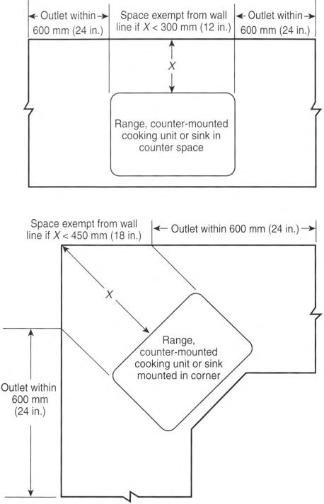
Exception No. 1: Receptacle outlets shall not be required directly behind a range, counter-mounted cooking unit, or sink in the installation described in Figure 210.52(C)(1).
Exception No. 2: Where a required receptacle outlet cannot be installed in the wall areas shown in Figure 210.52(C)(1), the receptacle outlet shall be permitted to be installed as close as practicable to the countertop area to be served. The total number of receptacle outlets serving the countertop shall not be less than the number needed to satisfy 210.52(C)(1). These outlets shall be located in accordance with 210.52(C)(3).
FIGURE 210.52(C)(1) Determination of Area Behind a Range, Counter-Mounted Cooking Unit, or Sink.
(2) Island and Peninsular Countertops and Work Surfaces.
Receptacle outlets, if installed to serve an island or peninsular countertop or work surface, shall be installed in accordance with 210.52(C)(3). If a receptacle outlet is not provided to serve an island or peninsular countertop or work surface, provisions shall be provided at the island or peninsula for future addition of a receptacle outlet to serve the island or peninsular countertop or work surface.
(3) Receptacle Outlet Location.
Receptacle outlets shall be located in one or more of the following:
- On or above, but not more than 500 mm (20 in.) above, a countertop or work surface
- In a countertop using receptacle outlet assemblies listed for use in countertops
- In a work surface using receptacle outlet assemblies listed for use in work surfaces or listed for use in countertops
Receptacle outlets rendered not readily accessible by appliances fastened in place, appliance garages, sinks, or rangetops as covered in 210.52(C)(1), Exception No. 1, or appliances occupying assigned spaces shall not be considered as these required outlets.
Informational Note No. 1: See 406.5(E) for installation of receptacles in countertops and 406.5(F) for installation of receptacles in work surfaces. See 380.10 for installation of multioutlet assemblies.
Informational Note No. 2: See Informative Annex J and ANSI/ICC A117.1-2009, Standard on Accessible and Usable Buildings and Facilities, for additional information.
(D) Bathrooms.
At least one receptacle outlet shall be installed in bathrooms within 900 mm (3 ft) of the outside edge of each sink. The receptacle outlet shall be located on a wall or partition that is adjacent to the sink or sink countertop, located on the countertop, or installed on the side or face of the sink cabinet. In no case shall the receptacle be located more than 300 mm (12 in.) below the top of the sink or sink countertop. Receptacle outlet assemblies listed for use in countertops shall be permitted to be installed in the countertop.
Informational Note: See 406.5(E) and 406.5(G) for requirements on installation of receptacles in countertops.
(E) Outdoor Outlets.
(1) One-Family and Two-Family Dwellings.
For a one-family dwelling and each unit of a two-family dwelling that is at grade level, at least one receptacle outlet readily accessible from grade and not more than 2.0 m (61/2 ft) above grade level shall be installed at the front and back of the dwelling.
(2) Multifamily Dwellings.
For each dwelling unit of a multifamily dwelling where the dwelling unit is located at grade level and provided with individual exterior entrance/egress, at least one receptacle outlet readily accessible from grade and not more than 2.0 m (61/2 ft) above grade level shall be installed.
(3) Balconies, Decks, and Porches.
Balconies, decks, and porches that are within 102 mm (4 in.) horizontally of the dwelling unit shall have at least one receptacle outlet accessible from the balcony, deck, or porch. The receptacle outlet shall not be located more than 2.0 m (61/2 ft) above the balcony, deck, or porch walking surface.
(F) Laundry Areas.
In dwelling units, at least one receptacle outlet shall be installed in areas designated for the installation of laundry equipment.
Exception No. 1: A receptacle for laundry equipment shall not be required in a dwelling unit of a multifamily building where laundry facilities are provided on the premises for use by all building occupants.
Exception No. 2: A receptacle for laundry equipment shall not be required in other than one-family dwellings where laundry facilities are not to be installed or permitted.
(G) Basements, Garages, and Accessory Buildings.
For one- and two-family dwellings, and multifamily dwellings, at least one receptacle outlet shall be installed in the areas specified in 210.52(G)(1) through (G)(3). These receptacles shall be in addition to receptacles required for specific equipment. Receptacles supplying only a permanently installed premises security system shall not be considered as meeting these requirements.
(1) Garages.
In each attached garage and in each detached garage with electric power, at least one receptacle outlet shall be installed in each vehicle bay and not more than 1.7 m (51/2 ft) above the floor.
Exception: Garage spaces not attached to an individual dwelling unit of a multifamily dwelling shall not require a receptacle outlet in each vehicle bay.
(2) Accessory Buildings.
In each accessory building with electric power.
(3) Basements.
In each separate unfinished portion of a basement.
(H) Hallways.
In dwelling units, hallways of 3.0 m (10 ft) or more in length shall have at least one receptacle outlet.
As used in this subsection, the hallway length shall be considered the length along the centerline of the hallway without passing through a doorway.
(I) Foyers.
Foyers that are not part of a hallway in accordance with 210.52(H) and that have an area that is greater than 5.6 m2 (60 ft2) shall have a receptacle(s) located in each wall space 900 mm (3 ft) or more in width. Doorways, door-side windows that extend to the floor, and similar openings shall not be considered wall space.
210.60 Guest Rooms, Guest Suites, Dormitory Units, and Similar Occupancies.
(A) General.
Guest rooms or guest suites in hotels or motels, sleeping rooms in dormitory units, and similar occupancies shall have receptacle outlets installed in accordance with 210.52(A) and (D). Guest rooms or guest suites provided with permanent provisions for cooking shall have receptacle outlets installed in accordance with all of the applicable rules in 210.52.
(B) Receptacle Placement.
The total number of receptacle outlets shall not be less than required in 210.52(A). These receptacle outlets shall be permitted to be located conveniently for permanent furniture layout. At least two receptacle outlets shall be readily accessible. Where receptacles are installed behind the bed, the receptacle shall be located to prevent the bed from contacting any attachment plug that may be installed or the receptacle shall be provided with a suitable guard.
210.62 Show Windows.
At least one 125-volt, single-phase, 15- or 20-ampere-rated receptacle outlet shall be installed within 450 mm (18 in.) of the top of each show window. No point along the top of the window shall be farther than 1.8 m (6 ft) from a receptacle outlet.
210.63 Equipment Requiring Servicing.
A 125-volt, single-phase, 15- or 20-ampere-rated receptacle outlet shall be installed at an accessible location within 7.5 m (25 ft) of the equipment as specified in 210.63(A) and (B).
(A) Heating, Air-Conditioning, and Refrigeration Equipment.
The required receptacle outlet shall be located on the same level as the heating, air-conditioning, and refrigeration equipment. The receptacle outlet shall not be connected to the load side of the equipment's branch-circuit disconnecting means.
Exception: A receptacle outlet shall not be required at one- and two-family dwellings for the service of evaporative coolers.
(B) Other Electrical Equipment.
In other than one- and two-family dwellings, a receptacle outlet shall be located as specified in 210.63(B)(1) and (B)(2).
(1) Indoor Service Equipment.
The required receptacle outlet shall be located within the same room or area as the service equipment.
(2) Indoor Equipment Requiring Dedicated Equipment Spaces.
Where equipment, other than service equipment, requires dedicated equipment space as specified in 110.26(E), the required receptacle outlet shall be located within the same room or area as the electrical equipment and shall not be connected to the load side of the equipment's disconnecting means.
210.65 Meeting Rooms.
(A) General.
Each meeting room of not more than 93 m2 (1000 ft2) in other than dwelling units shall have outlets for nonlocking-type, 125-volt, 15- or 20-ampere receptacles. The outlets shall be installed in accordance with 210.65(B). Where a room or space is provided with movable partition(s), each room size shall be determined with the partition in the position that results in the smallest size meeting room.
Informational Note No. 1: For the purposes of this section, meeting rooms are typically designed or intended for the gathering of seated occupants for such purposes as conferences, deliberations, or similar purposes, where portable electronic equipment such as computers, projectors, or similar equipment is likely to be used.
Informational Note No. 2: Examples of rooms that are not meeting rooms include auditoriums, schoolrooms, and coffee shops.
(B) Receptacle Outlets Required.
The total number of receptacle outlets, including floor outlets and receptacle outlets in fixed furniture, shall not be less than as determined in 210.65(B)(1) and (B)(2).
(1) Receptacle Outlets in Fixed Walls.
The required number of receptacle outlets shall be determined in accordance with 210.52(A)(1) through (A)(4). These receptacle outlets shall be permitted to be located as determined by the installer, designer, or building owner.
(2) Floor Outlets.
A meeting room with any floor dimension that is 3.7 m (12 ft) or greater in any direction and that has a floor area of at least 20 m2 (215 ft2) shall have at least one floor receptacle outlet, or at least one floor outlet to serve a receptacle(s), located at a distance not less than 1.8 m (6 ft) from any fixed wall for each 20 m2 (215 ft2) or fraction thereof.
Informational Note No. 1: See 314.27(B) for requirements on floor boxes used for receptacles located in the floor.
Informational Note No. 2: See 518.1 for requirements on assembly occupancies designed for 100 or more persons.
210.70 Lighting Outlets Required.
Lighting outlets shall be installed where specified in 210.70(A), (B), and (C). The switch or wall-mounted control device shall not rely exclusively on a battery unless a means is provided for automatically energizing the lighting outlets upon battery failure.
(A) Dwelling Units.
(1) Habitable Rooms, Kitchens, Laundry Areas, and Bathrooms.
At least one lighting outlet controlled by a listed wall-mounted control device shall be installed in every habitable room, kitchen, laundry area, and bathroom. The wall-mounted control device shall be located near an entrance to the room on a wall.
Exception No. 1: In other than kitchens, laundry areas, and bathrooms, one or more receptacles controlled by a listed wall-mounted control device shall be permitted in lieu of lighting outlets.
Exception No. 2: Lighting outlets shall be permitted to be controlled by occupancy sensors that are (1) in addition to listed wall-mounted control devices or (2) located at a customary wall switch location and equipped with a manual override that will allow the sensor to function as a wall switch.
(2) Additional Locations.
Additional lighting outlets shall be installed in accordance with the following:
- At least one lighting outlet controlled by a listed wall-mounted control device shall be installed in hallways, stairways, attached garages, detached garages, and accessory buildings with electric power.
- For dwelling units, attached garages, and detached garages with electric power, at least one exterior lighting outlet controlled by a listed wall-mounted control device shall be installed to provide illumination on the exterior side of outdoor entrances or exits with grade-level access. A vehicle door in a garage shall not be considered as an outdoor entrance or exit.Exception to (2): For an outdoor, grade-level bulkhead door with stairway access to a sub-grade-level basement, the required lighting outlet that provides illumination on the stairway steps shall be permitted to be located in the basement interior within 1.5 m (5 ft) horizontally of the bottommost stairway riser. This interior lighting outlet shall be permitted to be controlled by a listed wall-mounted control device or by a unit switch of the interior luminaire or interior lampholder.
- Where lighting outlets are installed for an interior stairway with six or more risers between floor levels, there shall be a listed wall-mounted control device at each floor level and at each landing level that includes a stairway entry to control the lighting outlets.
- Dimmer control of lighting outlets installed in accordance with 210.70(A)(2)(3) shall not be permitted unless the listed control devices can provide dimming control to maximum brightness at each control location for the interior stairway illumination.
(B) Guest Rooms or Guest Suites.
In hotels, motels, or similar occupancies, guest rooms or guest suites shall have at least one lighting outlet controlled by a listed wall-mounted control device installed in every habitable room and bathroom.
Exception No. 1: In other than bathrooms and kitchens where provided, one or more receptacles controlled by a listed wall-mounted control device shall be permitted in lieu of lighting outlets.
Exception No. 2: Lighting outlets shall be permitted to be controlled by occupancy sensors that are (1) in addition to listed wall-mounted control devices or (2) located at a customary wall switch location and equipped with a manual override that allows the sensor to function as a wall switch.
(C) All Occupancies.
For attics and underfloor spaces, utility rooms, and basements, at least one lighting outlet containing a switch or controlled by a wall switch or listed wall-mounted control device shall be installed where these spaces are used for storage or contain equipment requiring servicing. A point of control shall be at each entry that permits access to the attic and underfloor space, utility room, or basement. Where a lighting outlet is installed for equipment requiring service, the lighting outlet shall be installed at or near the equipment.
Article 215
Feeders
215.1 Scope.
This article covers the installation requirements, overcurrent protection requirements, minimum size, and ampacity of conductors for feeders not over 1000 volts ac or 1500 volts dc, nominal.
Informational Note: See Part III of Article 235 for feeders over 1000 volts ac or 1500 volts dc.
215.2 Minimum Rating and Size.
(A) General.
Feeder conductors shall have an ampacity not less than the larger of 215.2(A)(1) or (A)(2) and shall comply with 110.14(C).
(1) Continuous and Noncontinuous Loads.
Where a feeder supplies continuous loads or any combination of continuous and noncontinuous loads, the minimum feeder conductor size shall have an ampacity not less than the noncontinuous load plus 125 percent of the continuous load.
Exception No. 1: If the assembly, including the overcurrent devices protecting the feeder(s), is listed for operation at 100 percent of its rating, the ampacity of the feeder conductors shall be permitted to be not less than the sum of the continuous load plus the noncontinuous load.
Exception No. 2: Where a portion of a feeder is connected at both its supply and load ends to separately installed pressure connections as covered in 110.14(C)(2), it shall be permitted to have an ampacity not less than the sum of the continuous load plus the noncontinuous load. No portion of a feeder installed under this exception shall extend into an enclosure containing either the feeder supply or the feeder load terminations, as covered in 110.14(C)(1).
Exception No. 3: Grounded conductors that are not connected to an overcurrent device shall be permitted to be sized at 100 percent of the continuous and noncontinuous load.
(2) Ampacity Adjustment or Correction Factors.
The minimum feeder conductor size shall have an ampacity not less than the maximum load to be served after the application of any adjustment or correction factors in accordance with 310.14.
Informational Note No. 1: See Informative Annex D for Examples D1 through D11.
Informational Note No. 2: Conductors for feeders, as defined in Article 100, sized to prevent a voltage drop exceeding 3 percent at the farthest outlet of power, heating, and lighting loads, or combinations of such loads, and where the maximum total voltage drop on both feeders and branch circuits to the farthest outlet does not exceed 5 percent, will provide reasonable efficiency of operation.
Informational Note No. 3: See 210.19, Informational Note for voltage drop for branch circuits.
(B) Grounded Conductor.
The size of the feeder circuit grounded conductor shall not be smaller than the equipment grounding conductor size required by 250.122, except that 250.122(F) shall not apply where grounded conductors are run in parallel.
Additional minimum sizes shall be as specified in 215.2(C) under the conditions stipulated.
(C) Ampacity Relative to Service Conductors.
The feeder conductor ampacity shall not be less than that of the service conductors where the feeder conductors carry the total load supplied by service conductors with an ampacity of 55 amperes or less.
215.3 Overcurrent Protection.
Feeders shall be protected against overcurrent in accordance with Part I of Article 240. Where a feeder supplies continuous loads or any combination of continuous and noncontinuous loads, the rating of the overcurrent device shall not be less than the noncontinuous load plus 125 percent of the continuous load.
Exception: Where the assembly, including the overcurrent devices protecting the feeder(s), is listed for operation at 100 percent of its rating, the ampere rating of the overcurrent device shall be permitted to be not less than the sum of the continuous load plus the noncontinuous load.
215.4 Feeders With Common Neutral Conductor.
215.5 Diagrams of Feeders.
If required by the authority having jurisdiction, a diagram showing feeder details shall be provided prior to the installation of the feeders. Such a diagram shall show the area in square feet of the building or other structure supplied by each feeder, the total calculated load before applying demand factors, the demand factors used, the calculated load after applying demand factors, and the size and type of conductors to be used.
215.6 Feeder Equipment Grounding Conductor.
Where a feeder supplies branch circuits in which equipment grounding conductors are required, the feeder shall include or provide an equipment grounding conductor, to which the equipment grounding conductors of the branch circuits shall be connected. Where the feeder supplies a separate building or structure, the requirements of 250.32 shall apply.
215.7 Ungrounded Conductors Tapped From Grounded Systems.
Two-wire dc circuits and ac circuits of two or more ungrounded conductors shall be permitted to be tapped from the ungrounded conductors of circuits having a grounded neutral conductor. Switching devices in each tapped circuit shall have a pole in each ungrounded conductor.
215.9 Ground-Fault Circuit-Interrupter Protection for Personnel.
Feeders shall be permitted to be protected by a listed ground-fault circuit interrupter installed in a readily accessible location in lieu of the provisions for such interrupters as specified in 210.8 and 590.6(A).
215.10 Ground-Fault Protection of Equipment.
Each feeder disconnect rated 1000 amperes or more and installed on solidly grounded wye electrical systems of more than 150 volts to ground, but not exceeding 1000 volts phase-to-phase, shall be provided with ground-fault protection of equipment in accordance with 230.95.
Informational Note: See 517.17 for buildings that contain health care occupancies.
Exception No. 1: This section shall not apply to a disconnecting means for a continuous industrial process where a nonorderly shutdown will introduce additional or increased hazards.
Exception No. 2: This section shall not apply if ground-fault protection of equipment is provided on the supply side of the feeder and on the load side of any transformer supplying the feeder.
Exception No. 3: If temporary feeder conductors are used to connect a generator to a facility for repair, maintenance, or emergencies, ground-fault protection of equipment shall not be required. Temporary feeders without ground-fault protection shall be permitted for the time period necessary but shall not exceed 90 days.
215.11 Circuits Derived From Autotransformers.
Feeders shall not be derived from autotransformers unless the system supplied has a grounded conductor that is electrically connected to a grounded conductor of the system supplying the autotransformer.
Exception No. 1: An autotransformer shall be permitted without the connection to a grounded conductor where transforming from a nominal 208 volts to a nominal 240-volt supply or similarly from 240 volts to 208 volts.
Exception No. 2: In industrial occupancies, where conditions of maintenance and supervision ensure that only qualified persons service the installation, autotransformers shall be permitted to supply nominal 600-volt loads from nominal 480-volt systems, and 480-volt loads from nominal 600-volt systems, without the connection to a similar grounded conductor.
215.12 Identification for Feeders.
(C) Identification of Ungrounded Conductors.
(1) Feeders Supplied From More Than One Nominal Voltage System.
Where the premises wiring system has feeders supplied from more than one nominal voltage system, each ungrounded conductor of a feeder shall be identified by phase or line and system at all termination, connection, and splice points in compliance with 215.12(C)(1)(a) and (C)(1)(b).
- Means of Identification. The means of identification shall be permitted to be by separate color coding, marking tape, tagging, or other approved means.
- Posting of Identification Means. The method utilized for conductors originating within each feeder panelboard or similar feeder distribution equipment shall be documented in a manner that is readily available or shall be permanently posted at each feeder panelboard or similar feeder distribution equipment.
(2) Feeders Supplied From Direct-Current Systems.
Where a feeder is supplied from a dc system operating at more than 60 volts, each ungrounded conductor of 4 AWG or larger shall be identified by polarity at all termination, connection, and splice points by marking tape, tagging, or other approved means; each ungrounded conductor of 6 AWG or smaller shall be identified by polarity at all termination, connection, and splice points in compliance with 215.12(C)(2)(a) and (C)(2)(b). The identification methods utilized for conductors originating within each feeder panelboard or similar feeder distribution equipment shall be documented in a manner that is readily available or shall be permanently posted at each feeder panelboard or similar feeder distribution equipment.
- Positive Polarity, Sizes 6 AWG or Smaller. Where the positive polarity of a dc system does not serve as the connection for the grounded conductor, each positive ungrounded conductor shall be identified by one of the following means:
- A continuous red outer finish
- A continuous red stripe durably marked along the conductor's entire length on insulation of a color other than green, white, gray, or black
- Imprinted plus signs (+) or the word POSITIVE or POS durably marked on insulation of a color other than green, white, gray, or black, and repeated at intervals not exceeding 610 mm (24 in.) in accordance with 310.8(B)
- An approved permanent marking means such as sleeving or shrink-tubing that is suitable for the conductor size, at all termination, connection, and splice points, with imprinted plus signs (+) or the word POSITIVE or POS durably marked on insulation of a color other than green, white, gray, or black
- Negative Polarity, Sizes 6 AWG or Smaller. Where the negative polarity of a dc system does not serve as the connection for the grounded conductor, each negative ungrounded conductor shall be identified by one of the following means:
- A continuous black outer finish
- A continuous black stripe durably marked along the conductor's entire length on insulation of a color other than green, white, gray, or red
- Imprinted minus signs (—) or the word NEGATIVE or NEG durably marked on insulation of a color other than green, white, gray, or red, and repeated at intervals not exceeding 610 mm (24 in.) in accordance with 310.8(B)
- An approved permanent marking means such as sleeving or shrink-tubing that is suitable for the conductor size, at all termination, connection, and splice points, with imprinted minus signs (—) or the word NEGATIVE or NEG durably marked on insulation of a color other than green, white, gray, or red
215.15 Barriers.
Barriers shall be placed such that no energized, uninsulated, ungrounded busbar or terminal is exposed to inadvertent contact by persons or maintenance equipment while servicing load terminations in panelboards, switchboards, switchgear, or motor control centers supplied by feeder taps in 240.21(B) or transformer secondary conductors in 240.21(C) when the disconnecting device, to which the tap conductors are terminated, is in the open position.
215.18 Surge Protection.
(A) Surge-Protective Device.
Where a feeder supplies any of the following, a surge-protective device (SPD) shall be installed:
- Dwelling units
- Dormitory units
- Guest rooms and guest suites of hotels and motels
- Areas of nursing homes and limited-care facilities used exclusively as patient sleeping rooms
(B) Location.
The SPD shall be installed in or adjacent to distribution equipment, connected to the load side of the feeder, that contains branch circuit overcurrent protective device(s) that supply the locations specified in 215.18(A).
Informational Note: Surge protection is most effective when closest to the branch circuit. Surges can be generated from multiple sources including, but not limited to, lightning, the electric utility, or utilization equipment.
(E) Ratings.
SPDs shall have a nominal discharge current rating (In) of not less than 10kA.
Article 220
Branch-Circuit, Feeder, and Service Load Calculations
220.1 Scope.
This article provides requirements for calculating branch-circuit, feeder, and service loads. Part I provides general requirements for calculation methods. Part II provides calculation methods for branch-circuit loads. Part III and Part IV provide calculation methods for feeder and service loads. Part V provides calculation methods for farm loads. Part VI provides calculation methods for health care facilities. Part VII provides calculation methods for marinas, boatyards, floating buildings, and commercial and noncommercial docking facilities. 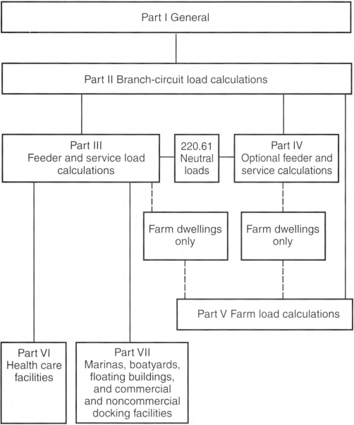
Informational Note No. 1: See Informative Annex D for examples.
Informational Note No. 2: See Informational Note Figure 220.1 for information on the organization of this article.
220.3 Other Articles for Specific-Purpose Calculations.
Table 220.3 shall provide references for specific-purpose calculation requirements not located in Chapters 5, 6, or 7 that amend or supplement the requirements of this article.
Table 220.3 Specific-Purpose Calculation References.
| Calculation | Article | Section (or Part) |
|---|---|---|
| Air-conditioning and refrigerating equipment, branch-circuit conductor sizing | 440 | Part IV |
| Capacitors | 460 | 460.8 |
| Fixed electric heating equipment for pipelines and vessels, branch-circuit sizing | 427 | 427.4 |
| Fixed electric space-heating equipment, branch-circuit sizing | 424 | 424.3 |
| Fixed outdoor electric deicing and snow-melting equipment, branch-circuit sizing | 426 | 426.4 |
| Fixed resistance and electrode industrial process heating equipment | 425 | 425.4 |
| Motors, feeder demand factor | 430 | 430.26 |
| Motors, multimotor and combination-load equipment | 430 | 430.25 |
| Motors, several motors or a motor(s) and other load(s) | 430 | 430.24 |
| Over 1000-volt ac and 1500-volt dc branch-circuit calculations | 235 | 235.19 |
| Over 1000-volt feeder calculations | 215 | 215.2(B) |
| Phase converters, conductors | 455 | 455.6 |
| Storage-type water heaters | 422 | 422.11 |
220.5 Calculations.
(B) Fractions of an Ampere.
Calculations shall be permitted to be rounded to the nearest whole ampere, with decimal fractions smaller than 0.5 dropped.
(C) Floor Area.
The floor area for each floor shall be calculated from the outside dimensions of the building, dwelling unit, or other area involved. For dwelling units, the calculated floor area shall not include open porches or unfinished areas not adaptable for future use as a habitable room or occupiable space.
220.10 General.
Branch-circuit loads shall be calculated in accordance with the following sections:
- 220.14 for other loads - all occupancies
- 220.16 for additions to existing installations
- 220.41 for dwelling units
- 220.42 for lighting loads for non-dwelling occupancies
- 220.44 for hotel and motel occupancies
220.11 Maximum Load.
The total load on a branch circuit shall not exceed the rating of the branch circuit nor the maximum loads specified in 220.11(A) through (C) under the conditions specified therein.
(A) Motor-Operated and Combination Loads.
Where a circuit supplies only motor-operated loads, the conductor sizing requirement specified in 430.22 shall apply. Where a circuit supplies only air-conditioning equipment, refrigerating equipment, or both, the requirements of 440.6 shall apply. For circuits supplying loads consisting of motor-operated utilization equipment that is fastened in place and has a motor larger than 1/8 hp in combination with other loads, the total calculated load shall be based on 125 percent of the largest motor load plus the sum of the other loads in accordance with 430.24.
(B) Inductive and LED Lighting Loads.
For circuits supplying lighting units that have ballasts, transformers, autotransformers, or LED drivers, the calculated load shall be based on the total ampere ratings of such units and not on the total watts of the lamps.
(C) Electric Cooking Appliances.
Applying demand factors for ranges, wall-mounted ovens, counter-mounted cooking units, and other household cooking appliance loads in excess of 13/4 kW shall be permitted in accordance with Table 220.55, including Notes 4, 5, and 6.
220.14 Other Loads - All Occupancies.
Branch-circuit load calculations shall include calculation of a minimum load on each outlet as calculated in 220.14(A) through (K) and then summed to establish the load on the branch circuit.
In all occupancies, the minimum load for each outlet for general-use receptacles and outlets not used for general illumination shall not be less than that calculated in 220.14(A) through (K), with the loads shown being based on nominal branch-circuit voltages.
Exception: The loads of outlets serving switchboards and switching frames in telephone exchanges shall be waived from the calculations.
(B) Electric Dryers and Electric Cooking Appliances in Dwellings and Household Cooking Appliances Used in Instructional Programs.
Load calculations shall be permitted as specified in 220.54 for electric dryers and in 220.55 for electric ranges and other cooking appliances.
(E) Heavy-Duty Lampholders.
Outlets for heavy-duty lampholders shall be calculated at a minimum of 600 volt-amperes.
(F) Sign and Outline Lighting.
Sign and outline lighting outlets shall be calculated at a minimum of 1200 volt-amperes for each required branch circuit specified in 600.5(A).
(G) Show Windows.
Show windows shall be calculated in accordance with either of the following:
- The unit load per outlet as required in other provisions of this section
- At 200 volt-amperes per linear 300 mm (1 ft) of show window
(H) Fixed Multioutlet Assemblies.
Fixed multioutlet assemblies used in other than dwelling units or the guest rooms or guest suites of hotels or motels shall be calculated in accordance with the following:
- Where appliances are unlikely to be used simultaneously, each 1.5 m (5 ft) or fraction thereof of each separate and continuous length shall be considered as one outlet of not less than 180 volt-amperes.
- Where appliances are likely to be used simultaneously, each 300 mm (1 ft) or fraction thereof shall be considered as an outlet of not less than 180 volt-amperes.
For the purposes of this section, the calculation shall be permitted to be based on the portion that contains receptacles.
(I) Receptacle Outlets.
Except as covered in 220.41 and 220.14(J), receptacle outlets shall be calculated at not less than 180 volt-amperes for each single or for each multiple receptacle on one yoke. A single piece of equipment consisting of a multiple receptacle comprised of four or more receptacles shall be calculated at not less than 90 volt-amperes per receptacle. This provision shall not be applicable to the receptacle outlets specified in 210.11(C)(1) and (C)(2).
(J) Receptacle Outlets in Office Buildings.
In office buildings, the receptacle loads shall be calculated to be the larger of the following:
- The calculated load from 220.14(I)
- 11 volt-amperes/m2 (1 volt-ampere/ft2)
220.16 Loads for Additions to Existing Installations.
(A) Dwelling Units.
Loads added to an existing dwelling unit(s) shall comply with the following as applicable:
- Loads for structural additions to an existing dwelling unit or for a previously unwired portion of an existing dwelling unit shall be calculated in accordance with 220.14.
- Loads for new circuits or extended circuits in previously wired dwelling units shall be calculated in accordance with 220.14.
(B) Other Than Dwelling Units.
Loads for new circuits or extended circuits in other than dwelling units shall be calculated in accordance with either 220.42 or 220.14, as applicable.
220.40 General.
The calculated load of a feeder or service shall not be less than the sum of the loads on the branch circuits supplied, as determined by Part II of this article, after any applicable demand factors permitted or required by Part III, IV, V, VI, or VII have been applied.
Informational Note No. 1: See Informative Annex D, Examples D1(a) through D10, for examples of feeder and service load calculations.
Informational Note No. 2: See 220.11(B) for the maximum load in amperes permitted for lighting units operating at less than 100 percent power factor.
220.41 Dwelling Units, Minimum Unit Load.
In one-family, two-family, and multifamily dwellings, the minimum unit load shall be not less than 33 volt-amperes/m2 (3 volt-amperes/ft2).
Unit loads include the following lighting and receptacle outlets, and no additional load calculations shall be required:
- All general-use receptacle outlets of 20-ampere rating or less, including receptacles connected to the circuits specified in 210.11(C)(3) and (C)(4)
- The receptacle outlets specified in 210.52(E) and (G)
- The lighting outlets specified in 210.70
The minimum lighting load shall be determined using the minimum unit load and the floor area as determined in 220.5(C) for dwelling occupancies. Motors rated less than 1/8 hp and connected to a lighting circuit shall be considered part of the minimum lighting load.
220.42 Lighting Load for Non-Dwelling Occupancies.
(A) General.
A unit load of not less than that specified in Table 220.42(A) for non-dwelling occupancies and the floor area determined in 220.5(C) shall be used to calculate the minimum lighting load. Motors rated less than 1/8 HP and connected to a lighting circuit shall be considered general lighting load.
Informational Note: The unit values of Table 220.42(A) are based on minimum load conditions and 80 percent power factor and might not provide sufficient capacity for the installation contemplated.
Table 220.42(A) General Lighting Loads by Non-Dwelling Occupancy.
| Type of Occupancy | Unit Load | |
|---|---|---|
| Volt-amperes/m2 | Volt-amperes/ft2 | |
| Automotive facility | 16 | 1.5 |
| Convention center | 15 | 1.4 |
| Courthouse | 15 | 1.4 |
| Dormitory | 16 | 1.5 |
| Exercise center | 15 | 1.4 |
| Fire station | 14 | 1.3 |
| Gymnasium1 | 18 | 1.7 |
| Health care clinic | 17 | 1.6 |
| Hospital | 17 | 1.6 |
| Hotel or motel, or apartment house without provisions for cooking by tenants2 | 18 | 1.7 |
| Library | 16 | 1.5 |
| Manufacturing facility3 | 24 | 2.2 |
| Motion picture theater | 17 | 1.6 |
| Museum | 17 | 1.6 |
| Office4 | 14 | 1.3 |
| Parking garage5 | 3 | 0.3 |
| Penitentiary | 13 | 1.2 |
| Performing arts theater | 16 | 1.5 |
| Police station | 14 | 1.3 |
| Post office | 17 | 1.6 |
| Religious facility | 24 | 2.2 |
| Restaurant6 | 16 | 1.5 |
| Retail7,8 | 20 | 1.9 |
| School/university | 16 | 1.5 |
| Sports arena | 16 | 1.5 |
| Town hall | 15 | 1.4 |
| Transportation | 13 | 1.2 |
| Warehouse | 13 | 1.2 |
| Workshop | 18 | 1.7 |
Note: The 125 percent multiplier for a continuous load as specified in 210.20(A) is included, therefore no additional multiplier shall be required when using the unit loads in this table for calculating the minimum lighting load for a specified occupancy.
1Armories and auditoriums are considered gymnasium-type occupancies.
2Lodge rooms are similar to hotels and motels.
3Industrial commercial loft buildings are considered manufacturing-type occupancies.
4Banks are office-type occupancies.
6Clubs are considered restaurant occupancies.
7Barber shops and beauty parlors are considered retail occupancies.
8Stores are considered retail occupancies.
(B) Energy Code.
Where the building is designed and constructed to comply with an energy code adopted by the local authority, the lighting load shall be permitted to be calculated using the unit values specified in the energy code where the following conditions are met:
- A power monitoring system is installed that will provide continuous information regarding the total general lighting load of the building.
- The power monitoring system will be set with alarm values to alert the building owner or manager if the lighting load exceeds the values set by the energy code. Automatic means to take action to reduce the connected load shall be permitted.
- The demand factors specified in 220.45 are not applied to the general lighting load.
- The continuous load multiplier of 125 percent shall be applied.
220.43 Office Buildings.
In office buildings, the receptacle loads shall be calculated to be the larger of the following:
- The calculated load from 220.14(1) after Table 220.47 demand factors have been applied
- 11 volt-amperes/m2 or 1 volt-ampere/ft2
220.44 Hotel and Motel Occupancies.
In guest rooms or guest suites of hotels and motels, the following lighting and receptacle outlets are included in the minimum unit load in Table 220.42(A), and no additional load calculations shall be required for such outlets:
- All general-use receptacle outlets of 20-ampere rating or less, including receptacles connected to the circuits in 210.11(C)(3) and (C)(4)
- The receptacle outlets specified in 210.52(E)(3)
- The lighting outlets specified in 210.70
220.45 General Lighting.
The demand factors specified in Table 220.45 shall apply to that portion of the total branch-circuit load calculated for general illumination. They shall not be applied in determining the number of branch circuits for general illumination.
Table 220.45 Lighting Load Demand Factors.
| Type of Occupancy | Portion of Lighting Load to Which Demand Factor Applies (Volt-Amperes) | Demand Factor (%) |
|---|---|---|
| Dwelling units | First 3000 at | 100 |
| From 3001 to 120,000 at | 35 | |
| Remainder over 120,000 at | 25 | |
| Hotels and motels, including apartment houses without provision for cooking by tenants* | First 20,000 or less at | 60 |
| From 20,001 to 100,000 at | 50 | |
| Remainder over 100,000 at | 35 | |
| Warehouses (storage) | First 12,500 or less at | 100 |
| Remainder over 12,500 at | 50 | |
| All others | Total volt-amperes | 100 |
*The demand factors of this table shall not apply to the calculated load of feeders or services supplying areas in hotels and motels where the entire lighting is likely to be used at one time, as in ballrooms or dining rooms.
220.46 Show-Window and Track Lighting.
(A) Show Windows.
For show-window lighting, a load of not less than 660 volt-amperes/linear meter or 200 volt-amperes/linear foot shall be included for a show window, measured horizontally along its base.
Informational Note: See 220.14(G) for branch circuits supplying show windows.
(B) Track Lighting.
For track lighting in other than dwelling units or guest rooms or guest suites of hotels or motels, an additional load of 150 volt-amperes shall be included for every 600 mm (2 ft) of lighting track or fraction thereof. Where multicircuit track is installed, the load shall be considered to be divided equally between the track circuits.
220.47 Receptacle Loads - Other Than Dwelling Units.
Receptacle loads calculated in accordance with 220.14(H) and (I) shall be permitted to be made subject to the demand factors given in Table 220.45 or Table 220.47.
Table 220.47 Demand Factors for Non-Dwelling Receptacle Loads.
| Portion of Receptacle Load to Which Demand Factor Applies (Volt-Amperes) | Demand Factor (%) |
|---|---|
| First 10 kVA or less at | 100 |
| Remainder over 10 kVA at | 50 |
220.50 Motors and Air-Conditioning Equipment.
(A) Motors.
The conductor sizing requirements specified in 430.24 and 430.25 and the feeder demand factor calculation method specified in 430.26 shall be used to determine motor loads.
(B) Air-Conditioning Equipment.
The conductor sizing requirements specified in Part IV of Article 440 shall be used to determine air-conditioning loads for hermetic refrigerant motor-compressors.
220.51 Fixed Electric Space Heating.
Fixed electric space-heating loads shall be calculated at 100 percent of the total connected load. However, in no case shall a feeder or service load current rating be less than the rating of the largest branch circuit supplied.
Exception: If reduced loading of the conductors results from units operating on duty-cycle or intermittently, or from all units not operating at the same time, the authority having jurisdiction shall be permitted to grant permission for feeder and service conductors to have an ampacity less than 100 percent if the conductors have an ampacity for the load so determined.
220.52 Small-Appliance and Laundry Loads - Dwelling Unit.
(A) Small-Appliance Circuit Load.
In each dwelling unit, the load shall be calculated at 1500 volt-amperes for each 2-wire small-appliance branch circuit as covered by 210.11(C)(1). Where the load is subdivided through two or more feeders, the calculated load for each shall include not less than 1500 volt-amperes for each 2-wire small-appliance branch circuit. These loads shall be permitted to be included with the general lighting load and subjected to the demand factors provided in Table 220.45.
Exception: The individual branch circuit permitted by 210.52(B)(1), Exception No. 2, shall be permitted to be excluded from the calculation required by 220.52.
(B) Laundry Circuit Load.
A load of not less than 1500 volt-amperes shall be included for each 2-wire laundry branch circuit installed as covered by 210.11(C)(2). This load shall be permitted to be included with the general lighting load and shall be subjected to the demand factors provided in Table 220.45.
220.53 Appliance Load - Dwelling Unit(s).
Applying a demand factor of 75 percent to the nameplate rating load of four or more appliances rated 1/4 hp or greater, or 500 watts or greater, that are fastened in place, and that are served by the same feeder or service in a one-family, two-family, or multifamily dwelling shall be permitted. This demand factor shall not apply to the following:
- Household electric cooking equipment that is fastened in place
- Clothes dryers
- Space heating equipment
- Air-conditioning equipment
- Electric vehicle supply equipment (EVSE)
220.54 Electric Clothes Dryers - Dwelling Unit(s).
The load for household electric clothes dryers in a dwelling unit(s) shall be either 5000 watts (volt-amperes) or the nameplate rating, whichever is larger, for each dryer served. The use of the demand factors in Table 220.54 shall be permitted. Where two or more single-phase dryers are supplied by a 3-phase, 4-wire feeder or service, the total load shall be calculated on the basis of twice the maximum number connected between any two phases. Kilovolt-amperes (kVA) shall be considered equivalent to kilowatts (kW) for loads calculated in this section.
Table 220.54 Demand Factors for Household Electric Clothes Dryers.
| Number of Dryers | Demand Factor (%) |
|---|---|
| 1—4 | 100 |
| 5 | 85 |
| 6 | 75 |
| 7 | 65 |
| 8 | 60 |
| 9 | 55 |
| 10 | 50 |
| 11 | 47 |
| 12—23 | 47% minus 1% for each dryer exceeding 11 |
| 24—42 | 35% minus 0.5% for each dryer exceeding 23 |
| 43 and over | 25% |
220.55 Electric Cooking Appliances in Dwelling Units and Household Cooking Appliances Used in Instructional Programs.
The load for household electric ranges, wall-mounted ovens, counter-mounted cooking units, and other household cooking appliances individually rated in excess of 13/4 kW shall be permitted to be calculated in accordance with Table 220.55. Kilovolt-amperes (kVA) shall be considered equivalent to kilowatts (kW) for loads calculated under this section.
Where two or more single-phase ranges are supplied by a 3-phase, 4-wire feeder or service, the total load shall be calculated on the basis of twice the maximum number connected between any two phases.
Informational Note No. 1: See Informative Annex D for examples.
Informational Note No. 2: See Table 220.56 for demand factors for commercial cooking equipment.
Table 220.55 Demand Factors and Loads for Household Electric Ranges, Wall-Mounted Ovens, Counter-Mounted Cooking Units, and Other Household Cooking Appliances over 13/4 kW Rating (Column C to be used in all cases except as otherwise permitted in Note 3.).
| Number of Appliances | Demand Factor (%) (See Notes) | Column C Maximum Demand (kW) (See Notes) (Not over 12 kW Rating) | |
|---|---|---|---|
| Column A (Less than 31/2 kW Rating) | Column B (31/2 kW through 83/4 kW Rating) | ||
| 1 | 80 | 80 | 8 |
| 2 | 75 | 65 | 11 |
| 3 | 70 | 55 | 14 |
| 4 | 66 | 50 | 17 |
| 5 | 62 | 45 | 20 |
| 6 | 59 | 43 | 21 |
| 7 | 56 | 40 | 22 |
| 8 | 53 | 36 | 23 |
| 9 | 51 | 35 | 24 |
| 10 | 49 | 34 | 25 |
| 11 | 47 | 32 | 26 |
| 12 | 45 | 32 | 27 |
| 13 | 43 | 32 | 28 |
| 14 | 41 | 32 | 29 |
| 15 | 40 | 32 | 30 |
| 16 | 39 | 28 | 31 |
| 17 | 38 | 28 | 32 |
| 18 | 37 | 28 | 33 |
| 19 | 36 | 28 | 34 |
| 20 | 35 | 28 | 35 |
| 21 | 34 | 26 | 36 |
| 22 | 33 | 26 | 37 |
| 23 | 32 | 26 | 38 |
| 24 | 31 | 26 | 39 |
| 25 | 30 | 26 | 40 |
| 26—30 | 30 | 24 | 15 kW + 1 kW for each range |
| 31—40 | 30 | 22 | |
| 41—50 | 30 | 20 | 25 kW + 3/4 kW for each range |
| 51—60 | 30 | 18 | |
| 61 and over | 30 | 16 | |
Notes:
- Over 12 kW through 27 kW ranges all of same rating. For ranges individually rated more than 12 kW but not more than 27 kW, the maximum demand in Column C shall be increased 5 percent for each additional kilowatt of rating or major fraction thereof by which the rating of individual ranges exceeds 12 kW.
- Over 83/4 kW through 27 kW ranges of unequal ratings. For ranges individually rated more than 83/4 kW and of different ratings, but none exceeding 27 kW, an average value of rating shall be calculated by adding together the ratings of all ranges to obtain the total connected load (using 12 kW for any range rated less than 12 kW) and dividing by the total number of ranges. Then the maximum demand in Column C shall be increased 5 percent for each kilowatt or major fraction thereof by which this average value exceeds 12 kW.
- Over 13/4 kW through 83/4 kW. In lieu of the method provided in Column C, adding the nameplate ratings of all household cooking appliances rated more than 13/4 kW but not more than 83/4 kW and multiplying the sum by the demand factors specified in Column A or Column B for the given number of appliances shall be permitted. Where the rating of cooking appliances falls under both Column A and Column B, the demand factors for each column shall be applied to the appliances for that column, and the results added together.
- Calculating the branch-circuit load for one range in accordance with Table 220.55 shall be permitted.
- The branch-circuit load for one wall-mounted oven or one counter-mounted cooking unit shall be the nameplate rating of the appliance.
- The branch-circuit load for a counter-mounted cooking unit and not more than two wall-mounted ovens, all supplied from a single branch circuit and located in the same room, shall be calculated by adding the nameplate rating of the individual appliances and treating this total as equivalent to one range.
- This table shall also apply to household cooking appliances rated over 13/4 kW and used in instructional programs.
220.56 Kitchen Equipment - Other Than Dwelling Unit(s).
Calculating the load for commercial electric cooking equipment, dishwasher booster heaters, water heaters, and other kitchen equipment in accordance with Table 220.56 shall be permitted. Other kitchen equipment shall include equipment that is fastened in place and rated 1/4 hp or greater, or 500 watts or greater. These demand factors shall be applied to all equipment that has either thermostatic control or intermittent use as kitchen equipment. These demand factors shall not apply to space-heating, ventilating, or air-conditioning equipment.
Table 220.56 Demand Factors for Kitchen Equipment - Other Than Dwelling Unit(s).
| Number of Units of Equipment | Demand Factor (%) |
|---|---|
| 1 | 100 |
| 2 | 100 |
| 3 | 90 |
| 4 | 80 |
| 5 | 70 |
| 6 and over | 65 |
220.57 Electric Vehicle Supply Equipment (EVSE) Load.
The EVSE load shall be calculated at either 7200 watts (volt-amperes) or the nameplate rating of the equipment, whichever is larger.
220.60 Noncoincident Loads.
If it is unlikely that two or more noncoincident loads will be in use simultaneously, using only the largest load(s) that will be used at one time for calculating the total load of a feeder or service shall be permitted. If a motor or air-conditioning load is part of the noncoincident load and is not the largest of the noncoincident loads, 125 percent of either the motor load or air-conditioning load, whichever is larger, shall be used in the calculation.
220.61 Feeder or Service Neutral Load.
(A) Basic Calculation.
The feeder or service neutral load shall be the maximum unbalance of the load determined by this article. The maximum unbalanced load shall be the maximum net calculated load between the neutral conductor and any one ungrounded conductor.
Exception: For 3-wire, 2-phase or 5-wire, 2-phase systems, the maximum unbalanced load shall be the maximum net calculated load between the neutral conductor and any one ungrounded conductor multiplied by 140 percent.
(B) Permitted Reductions.
A service or feeder supplying the following loads shall be permitted to have an additional demand factor of 70 percent applied to the amount in 220.61(B)(1) and a portion of the amount in 220.61 (B)(2).
(1) Household Electric Ranges, Wall-Mounted Ovens, Counter-Mounted Cooking Units, and Dryers.
A feeder or service supplying household electric ranges, wall-mounted ovens, counter-mounted cooking units, and electric dryers, where the maximum unbalanced load has been determined in accordance with Table 220.55 for ranges and Table 220.54 for dryers.
(C) Prohibited Reductions.
There shall be no reduction of the neutral or grounded conductor capacity applied to the amount in 220.61 (C)(1), or portion of the amount in (C)(2), from that determined by the basic calculation:
- Any portion of a 3-wire circuit consisting of 2 ungrounded conductors and the neutral conductor of a 4-wire, 3-phase, wye-connected system
- That portion consisting of nonlinear loads supplied from a 4-wire, wye-connected, 3-phase system
Informational Note: A 3-phase, 4-wire, wye-connected power system used to supply power to nonlinear loads might necessitate that the power system design allows for the possibility of high harmonic neutral conductor currents.
220.70 Energy Management Systems (EMSs).
If an energy management system (EMS) is used to limit the current to a feeder or service in accordance with 750.30, a single value equal to the maximum ampere setpoint of the EMS shall be permitted to be used in load calculations for the feeder or service.
The setpoint value of the EMS shall be considered a continuous load for the purposes of load calculations.
220.82 Dwelling Unit.
(A) Feeder and Service Load.
This section applies to a dwelling unit having the total connected load served by a single 120/240-volt or 208Y/120-volt set of 3-wire service or feeder conductors with an ampacity of 100 or greater. It shall be permissible to calculate the feeder and service loads in accordance with this section instead of the method specified in Part III of this article. The calculated load shall be the result of adding the loads from 220.82(B) and (C). Feeder and service-entrance conductors whose calculated load is determined by this optional calculation shall be permitted to have the neutral load determined by 220.61.
(B) General Loads.
The general calculated load shall be not less than 100 percent of the first 10 kVA plus 40 percent of the remainder of the following loads:
- 33 volt-amperes/m2 or 3 volt-amperes/ft2 for general lighting and general-use receptacles. The floor area for each floor shall be calculated from the outside dimensions of the dwelling unit. The calculated floor area shall not include open porches, garages, or unused or unfinished spaces not adaptable for future use.
- 1500 volt-amperes for each 2-wire, 20-ampere small-appliance branch circuit and each laundry branch circuit covered in 210.11(C)(1) and (C)(2).
- The nameplate rating of the following:
- All appliances that are fastened in place, permanently connected, or located to be on a specific circuit
- Ranges, wall-mounted ovens, counter-mounted cooking units
- Clothes dryers that are not connected to the laundry branch circuit specified in 220.82(B)(2)
- Water heaters
- The nameplate ampere or kVA rating of all permanently connected motors not included in 220.82(B)(3).
(C) Heating and Air-Conditioning Load.
The largest of the following six selections (load in kVA) shall be included:
- 100 percent of the nameplate rating(s) of the air conditioning and cooling.
- 100 percent of the nameplate rating(s) of the heat pump when the heat pump is used without any supplemental electric heating.
- 100 percent of the nameplate rating(s) of the heat pump compressor and 65 percent of the supplemental electric heating for central electric space-heating systems. If the heat pump compressor is prevented from operating at the same time as the supplementary heat, it does not need to be added to the supplementary heat for the total central space heating load.
- 65 percent of the nameplate rating(s) of electric space heating if less than four separately controlled units.
- 40 percent of the nameplate rating(s) of electric space heating if four or more separately controlled units.
- 100 percent of the nameplate ratings of electric thermal storage and other heating systems where the usual load is expected to be continuous at the full nameplate value. Systems qualifying under this selection shall not be calculated under any other selection in 220.82(C).
220.83 Existing Dwelling Unit.
This section shall be permitted to be used to determine if the existing service or feeder is of sufficient capacity to serve additional loads. Where the dwelling unit is served by a 120/240-volt or 208Y/120-volt, 3-wire service or feeder, calculating the total load in accordance with 220.83(A) or (B) shall be permitted.
(A) Where Additional Air-Conditioning Equipment or Electric Space-Heating Equipment Is Not to Be Installed.
The percentages listed in Table 220.83(A) shall be used for existing and additional new loads.
Load calculations shall include the following:
- General lighting and general-use receptacles at 33 volt-amperes/m2 or 3 volt-amperes/ft2 as determined by 220.42
- 1500 volt-amperes for each 2-wire, 20-ampere small-appliance branch circuit and each laundry branch circuit covered in 210.11(C)(1) and (C)(2)
- The nameplate rating of the following:
- All appliances that are fastened in place, permanently connected, or located to be on a specific circuit
- Ranges, wall-mounted ovens, counter-mounted cooking units
- Clothes dryers that are not connected to the laundry branch circuit specified in item (2)
- Water heaters
Table 220.83(A) Without Additional Air-Conditioning or Electric Space-Heating Equipment.
| Load (kVA) | Percent of Load |
|---|---|
| First 8 kVA of load at | 100 |
| Remainder of load at | 40 |
(B) Where Additional Air-Conditioning Equipment or Electric Space-Heating Equipment Is to Be Installed.
The percentages listed in Table 220.83(B) shall be used for existing and additional new loads. The larger connected load of air conditioning or space heating, but not both, shall be used.
Other loads shall include the following:
- General lighting and general-use receptacles at 33 volt-amperes/m2 or 3 volt-amperes/ft2 as determined by 220.42
- 1500 volt-amperes for each 2-wire, 20-ampere small-appliance branch circuit and each laundry branch circuit covered in 210.11(C)(1) and (C)(2)
- The nameplate rating of the following:
- All appliances that are fastened in place, permanently connected, or located to be on a specific circuit
- Ranges, wall-mounted ovens, counter-mounted cooking units
- Clothes dryers that are not connected to the laundry branch circuit specified in item (2)
- Water heaters
220.84 Multifamily Dwelling.
(A) Feeder or Service Load.
It shall be permissible to calculate the load of a feeder or service that supplies three or more dwelling units of a multifamily dwelling in accordance with Table 220.84(B) instead of Part III of this article if all the following conditions are met:
- No dwelling unit is supplied by more than one feeder.
- Each dwelling unit is equipped with electric cooking equipment.Exception: When the calculated load for multifamily dwellings without electric cooking in Part III of this article exceeds that calculated under Part IV for the identical load plus electric cooking (based on 8 kW per unit), the lesser of the two loads shall be permitted to be used.
- Each dwelling unit is equipped with either electric space heating or air conditioning, or both. Feeders and service conductors whose calculated load is determined by this optional calculation shall be permitted to have the neutral load determined by 220.61.
(B) House Loads.
House loads shall be calculated in accordance with Part III of this article and shall be in addition to the dwelling unit loads calculated in accordance with Table 220.84(B).
Table 220.84(B) Optional Calculations - Demand Factors for Three or More Multifamily Dwelling Units.
| Number of Dwelling Units | Demand Factor % |
|---|---|
| 3—5 | 45 |
| 6—7 | 44 |
| 8—10 | 43 |
| 11 | 42 |
| 12—13 | 41 |
| 14—15 | 40 |
| 16—17 | 39 |
| 18—20 | 38 |
| 21 | 37 |
| 22—23 | 36 |
| 24—25 | 35 |
| 26—27 | 34 |
| 28—30 | 33 |
| 31 | 32 |
| 32—33 | 31 |
| 34—36 | 30 |
| 37—38 | 29 |
| 39—42 | 28 |
| 43—45 | 27 |
| 46—50 | 26 |
| 51—55 | 25 |
| 56—61 | 24 |
| 62 and over | 23 |
(C) Calculated Loads.
The calculated load to which the demand factors of Table 220.84(B) apply shall include the following:
- 33 volt-amperes/m2 or 3 volt-amperes/ft2 for general lighting and general-use receptacles
- 1500 volt-amperes for each 2-wire, 20-ampere small-appliance branch circuit and each laundry branch circuit covered in 210.11(C)(1) and (C)(2)
- The nameplate rating of the following:
- All appliances that are fastened in place, permanently connected, or located to be on a specific circuit
- Ranges, wall-mounted ovens, counter-mounted cooking units
- Clothes dryers that are not connected to the laundry branch circuit specified in item (2)
- Water heaters
- The nameplate ampere or kVA rating of all permanently connected motors not included in item (3)
- The larger of the air-conditioning load or the fixed electric space-heating load
220.85 Two Dwelling Units.
Where two dwelling units are supplied by a single feeder or service and the calculated load under Part III of this article exceeds that for three identical units calculated under 220.84, the lesser of the two loads shall be permitted to be used.
220.86 Schools.
The calculation of a feeder or service load for schools shall be permitted in accordance with Table 220.86 in lieu of Part III of this article where equipped with electric space heating, air conditioning, or both. The connected load to which the demand factors of Table 220.86 apply shall include all of the interior and exterior lighting, power, water heating, cooking, other loads, and the larger of the air-conditioning load or space-heating load within the building or structure.
Feeders and service conductors whose calculated load is determined by this optional calculation shall be permitted to have the neutral load determined by 220.61. Where the building or structure load is calculated by this optional method, feeders within the building or structure shall have ampacity as permitted in Part III of this article; however, the ampacity of an individual feeder shall not be required to be larger than the ampacity for the entire building.
This section shall not apply to portable classroom buildings.
Table 220.86 Optional Method - Demand Factors for Feeders and Service Conductors for Schools.
| Connected Load | Demand Factor (%) | Calculated Loads (VA) | |
|---|---|---|---|
| Total VA/m2 | Total VA/ft2 | ||
| 0—33 | 0—3 | 100 | Amount × 100% |
| Over 33—220 | Over 3—20 | 75 | (Amount × 75%) + 3 |
| Remainder over 220 | Remainder over 20 | 25 | (Amount × 25%) + 15.75 |
220.87 Determining Existing Loads.
The calculation of a feeder or service load for existing installations shall be permitted to use actual maximum demand to determine the existing load under all of the following conditions:
- The maximum demand data is available for a 1-year period.Exception: If the maximum demand data for a 1-year period is not available, the calculated load shall be permitted to be based on the maximum demand (the highest average kilowatts reached and maintained for a 15-minute interval) continuously recorded over a minimum 30-day period using a recording ammeter or power meter connected to the highest loaded phase of the feeder or service, based on the initial loading at the start of the recording. The recording shall reflect the maximum demand of the feeder or service by being taken when the building or space is occupied and shall include by measurement or calculation the larger of the heating or cooling equipment load, and other loads that might be periodic in nature due to seasonal or similar conditions. This exception shall not be permitted if the feeder or service has a renewable energy system (i.e., solar photovoltaic or wind electric) or employs any form of peak load shaving.
- The maximum demand at 125 percent plus the new load does not exceed the ampacity of the feeder or rating of the service.
- The feeder has overcurrent protection in accordance with 240.4, and the service has overload protection in accordance with 230.90.
220.88 New Restaurants.
Calculation of a service or feeder load, where the feeder serves the total load, for a new restaurant shall be permitted in accordance with Table 220.88 in lieu of Part III of this article.
Table 220.88 Optional Method - Permitted Load Calculations for Service and Feeder Conductors for New Restaurants.
| Total Connected Load (kVA) | All Electric Restaurant | Not All Electric Restaurant |
|---|---|---|
| Calculated Loads (kVA) | Calculated Loads (kVA) | |
| 0—200 | 80% | 100% |
| 201—325 | 10% (amount over 200) + 160.0 | 50% (amount over 200) + 200.0 |
| 326—800 | 50% (amount over 325) + 172.5 | 45% (amount over 325) + 262.5 |
| Over 800 | 50% (amount over 800) + 410.0 | 20% (amount over 800) + 476.3 |
Note: Add all electrical loads, including both heating and cooling loads, to calculate the total connected load.
Select the one demand factor that applies from the table, then multiply the total connected load by this single demand factor.
220.102 Farm Loads - Buildings and Other Loads.
(A) Dwelling Unit.
The feeder or service load of a farm dwelling unit shall be calculated in accordance with the provisions for dwellings in Part III or IV of this article. Where the dwelling has electric heat and the farm has electric grain-drying systems, Part IV of this article shall not be used to calculate the dwelling load where the dwelling and farm loads are supplied by a common service.
(B) Other Than Dwelling Unit.
Where a feeder or service supplies a farm building or other load having two or more separate branch circuits, the load for feeders, service conductors, and service equipment shall be calculated in accordance with demand factors not less than indicated in Table 220.102(B).
Table 220.102(B) Method for Calculating Farm Loads for Other Than Dwelling Unit.
| Ampere Load at 240 Volts Maximum | Demand Factor (%) |
|---|---|
| The greater of the following: | |
| All loads that are expected to operate simultaneously, or | 100 |
| 125 percent of the full load current of the largest motor, or | |
| First 60 amperes of the load | |
| Next 60 amperes of all other loads | 50 |
| Remainder of other loads | 25 |
220.103 Farm Loads - Total.
Where supplied by a common service, the total load of the farm for service conductors and service equipment shall be calculated in accordance with the farm dwelling unit load and demand factors specified in Table 220.103. Where there is equipment in two or more farm equipment buildings or for loads having the same function, such loads shall be calculated in accordance with Table 220.102(B) and shall be permitted to be combined as a single load in Table 220.103 for calculating the total load.
Table 220.103 Method for Calculating Total Farm Load.
| Individual Loads Calculated in Accordance with Table 220.102 | Demand Factor (%) |
|---|---|
| Largest load | 100 |
| Second largest load | 75 |
| Third largest load | 65 |
| Remaining loads | 50 |
Note: To this total load, add the load of the farm dwelling unit calculated in accordance with Part III or IV of this article. Where the dwelling has electric heat and the farm has electric grain-drying systems, Part IV of this article shall not be used to calculate the dwelling load.
220.110 Receptacle Loads.
Receptacle loads calculated in accordance with 220.14(H) and (I) and supplied by branch circuits not exceeding 150 volts to ground shall be permitted to be subjected to the demand factors provided in Table 220.110(1) and Table 220.110(2) for health care facilities.
Informational Note No. 1: See Article 100 for the definitions of patient care space categories.
Informational Note No. 2: See 220.14(I) for the calculation of receptacle outlet loads.
Table 220.110(1) Demand Factors for Receptacles Supplied by General-Purpose Branch Circuits in Category 1 and Category 2 Patient Care Spaces.
| Portion of Receptacle Load to Which Demand Factor Applies (Volt-Amperes) | Demand Factor (%) |
|---|---|
| First 5000 or less | 100 |
| From 5001 to 10,000 | 50 |
| Remainder over 10,000 | 25 |
Table 220.110(2) Demand Factors for Receptacles Supplied by General-Purpose Branch Circuits in Category 3 and Category 4 Patient Care Spaces.
| Portion of Receptacle Load to Which Demand Factor Applies (Volt-Amperes) | Demand Factor (%) |
|---|---|
| First 10,000 or less | 100 |
| Remainder over 10,000 | 50 |
220.120 Receptacle Loads.
General lighting and other loads in marinas, boatyards, floating buildings, and commercial and noncommercial docking facilities shall be calculated in accordance with Part III of this article and, in addition, the demand factors set forth in Table 220.120 shall be permitted for each service or feeder circuit supplying receptacles that provide shore power for boats. These calculations shall be permitted to be modified as indicated in Notes (1) and (2) of Table 220.120. Where demand factors of Table 220.120 are applied, the demand factor specified in 220.61 (B) shall not be permitted.
Informational Note: These demand factors could be inadequate in areas of extreme hot or cold temperatures with loaded circuits for heating, air-conditioning, or refrigerating equipment.
Table 220.120 Demand Factors for Shore Power Receptacle Loads.
| Number of Shore Power Receptacles | Sum of the Rating of the Receptacles (%) |
|---|---|
| 1—4 | 100 |
| 5—8 | 90 |
| 9—14 | 80 |
| 15—30 | 70 |
| 31—40 | 60 |
| 41—50 | 50 |
| 51—70 | 40 |
| ≥71 | 30 |
Notes:
- Where shore power accommodations provide two receptacles specifically for an individual boat slip and these receptacles have different voltages (e.g., one 30-ampere, 125-volt and one 50-ampere, 125/250-volt), only the receptacle with the larger kilowatt demand shall be required to be calculated.
- For each shore powered pedestal being installed that includes an individual kilowatt-hour submeters for each slip and is being calculated using the criteria listed in Table 220.120, the total demand amperes shall be permitted to be multiplied by 0.9 to achieve the final demand amperes of the facility.
- If a circuit feeding a boat hoist and shore power for the same boat slip is shared, only the load with the larger kilowatt demand shall be required to be counted in the load calculation.
Article 225
Outside Branch Circuits and Feeders
225.1 Scope.
This article covers requirements for outside branch circuits and feeders not over 1000 volts ac or 1500 volts dc, nominal, run on or between buildings, structures, or poles on the premises; and electrical equipment and wiring for the supply of utilization equipment that is located on or attached to the outside of buildings, structures, or poles.
Informational Note: See Part IV of Article 235 for outside branch circuits and feeders over 1000 volts ac or 1500 volts dc.
225.3 Other Articles.
Application of other articles, including additional requirements to specific cases of equipment and conductors, is shown in Table 225.3.
Table 225.3 Other Articles.
| Equipment/Conductors | Article |
|---|---|
| Branch circuits | 210 |
| Class 1 power-limited circuits and Class 1 power-limited remote-control and signaling circuits | 724 |
| Class 2 and Class 3 remote-control, signaling, and power-limited circuits | 725 |
| Conductors for general wiring | 310 |
| Electrically driven or controlled irrigation machines | 675 |
| Electric signs and outline lighting | 600 |
| Feeders | 215 |
| Fire alarm systems | 760 |
| Fixed outdoor electric deicing and snow-melting equipment | 426 |
| Grounding and bonding | 250 |
| Hazardous (classified) locations | 500 |
| Marinas and boatyards | 555 |
| Medium-voltage conductors and cable | 311 |
| Messenger-supported wiring | 396 |
| Mobile homes, manufactured homes, and mobile home parks | 550 |
| Open wiring on insulators | 398 |
| Over 1000 volts, general | 495 |
| Overcurrent protection | 240 |
| Overcurrent protection for systems rated over 1000 volts ac, 1500 volts dc | 245 |
| Services | 230 |
| Services, feeders, and branch circuits over 1000 volts ac, 1500 volts dc | 235 |
| Solar photovoltaic systems | 690 |
| Swimming pools, fountains, and similar installations | 680 |
| Use and identification of grounded conductors | 200 |
225.4 Conductor Insulation.
Where within 3.0 m (10 ft) of any building or structure other than supporting poles or towers, open individual (aerial) overhead conductors shall be insulated for the nominal voltage. The insulation of conductors in cables or raceways, except Type MI cable, shall be of thermoset or thermoplastic type and, in wet locations, shall comply with 310.10(C). The insulation of conductors for festoon lighting shall be of the thermoset or thermoplastic type.
Exception: Equipment grounding conductors and grounded circuit conductors shall be permitted to be bare or covered as specifically permitted elsewhere in this Code.
225.6 Conductor Size and Support.
(A) Overhead Spans.
Open individual conductors shall not be smaller than 10 AWG copper or 8 AWG aluminum for spans up to 15 m (50 ft) in length, and 8 AWG copper or 6 AWG aluminum for a longer span unless supported by a messenger wire.
(B) Festoon Lighting.
Overhead conductors for festoon lighting shall not be smaller than 12 AWG unless the conductors are supported by messenger wires. In all spans exceeding 12 m (40 ft), the conductors shall be supported by messenger wire. The messenger wire shall be supported by strain insulators. Conductors or messenger wires shall not be attached to any fire escape, downspout, or plumbing equipment.
225.10 Wiring on Buildings (or Other Structures).
The installation of outside wiring on surfaces of buildings (or other structures) shall be permitted for circuits not exceeding 1000 volts, nominal, as the following:
- Auxiliary gutters
- Busways
- Cable trays
- Cablebus
- Electrical metallic tubing (EMT)
- Flexible metal conduit (FMC)
- Intermediate metal conduit (IMC)
- Liquidtight flexible metal conduit (LFMC)
- Liquidtight flexible nonmetallic conduit (LFNC)
- Messenger-supported wiring
- Open wiring on insulators
- Reinforced thermosetting resin conduit (RTRC)
- Rigid metal conduit (RMC)
- Rigid polyvinyl chloride conduit (PVC)
- Type MC cable
- Type MI cable
- Type SE cable
- Type TC-ER cable
- Type UF cable
- Wireways
225.11 Feeder and Branch-Circuit Conductors Entering, Exiting, or Attached to Buildings or Structures.
Feeder and branch-circuit conductors entering or exiting buildings or structures shall be installed in accordance with 230.52. Overhead branch circuits and feeders attached to buildings or structures shall be installed in accordance with 230.54.
225.12 Open-Conductor Supports.
Open conductors shall be supported on knobs, racks, brackets, or strain insulators, that are made of glass, porcelain, or other approved materials.
225.14 Open-Conductor Spacings.
Conductors shall comply with the spacings provided in Table 230.51 (C).
(A) Separation From Other Circuits.
Open conductors shall be separated from open conductors of other circuits or systems by not less than 100 mm (4 in.).
(B) Conductors on Poles.
Conductors on poles shall have a separation of not less than 300 mm (1 ft) where not placed on racks or brackets. Conductors supported on poles shall provide a horizontal climbing space not less than the following:
- Power conductors below communications conductors - 750 mm (30 in.)
- Power conductors alone or above communications conductors:
- 300 volts or less - 600 mm (24 in.)
- Over 300 volts - 750 mm (30 in.)
- Communications conductors below power conductors - same as power conductors
- Communications conductors alone - no requirement
225.17 Masts as Supports.
Only feeder or branch-circuit conductors specified within this section shall be permitted to be attached to the feeder and/or branch-circuit mast. Masts used for the support of final spans of feeders or branch circuits shall be installed in accordance with 225.17(A) and (B).
(A) Strength.
The mast shall have adequate strength or be supported by braces or guy wires to safely withstand the strain imposed by the overhead feeder or branch-circuit conductors. Hubs intended for use with a conduit serving as a mast for support of feeder or branch-circuit conductors shall be identified for use with a mast.
(B) Attachment.
Feeder and/or branch-circuit conductors shall not be attached to a mast where the connection is between a weatherhead or the end of the conduit and a coupling where the coupling is located above the last point of securement to the building or other structure, or where the coupling is located above the building or other structure.
225.18 Clearance for Overhead Conductors and Cables.
Overhead spans of open conductors and open multiconductor cables of not over 1000 volts, nominal, shall have a clearance of not less than the following:
- 3.0 m (10 ft) - above finished grade, sidewalks, or from any platform or projection that will permit personal contact where the voltage does not exceed 150 volts to ground and accessible to pedestrians only
- 3.7 m (12 ft) - over residential property and driveways, and those commercial areas not subject to truck traffic where the voltage does not exceed 300 volts to ground
- 4.5 m (15 ft) - for those areas listed in the 3.7 m (12 ft) classification where the voltage exceeds 300 volts to ground
- 5.5 m (18 ft) - over public streets, alleys, roads, parking areas subject to truck traffic, driveways on other than residential property, and other land traversed by vehicles, such as cultivated, grazing, forest, and orchard
- 7.5 m (241/2 ft) - over track rails of railroads
225.19 Clearances From Buildings for Conductors of Not Over 1000 Volts, Nominal.
Overhead spans of open conductors and open multiconductor cables shall comply with 225.19(A), (B), (C), and (D).
(A) Above Roofs.
Overhead spans of open conductors and open multiconductor cables shall have a vertical clearance of not less than 2.6 m (8 ft 6 in.) above the roof surface. The vertical clearance above the roof level shall be maintained for a distance not less than 900 mm (3 ft) in all directions from the edge of the roof.
Exception No. 1: The area above a roof surface subject to pedestrian or vehicular traffic shall have a vertical clearance from the roof surface in accordance with the clearance requirements of 225.18.
Exception No. 2: Where the voltage between conductors does not exceed 300, and the roof has a slope of 100 mm in 300 mm (4 in. in 12 in.) or greater, a reduction in clearance to 900 mm (3 ft) shall be permitted.
Exception No. 3: Where the voltage between conductors does not exceed 300, a reduction in clearance above only the overhanging portion of the roof to not less than 450 mm (18 in.) shall be permitted if (1) not more than 1.8 m (6 ft) of the conductors, 1.2 m (4 ft) horizontally, pass above the roof overhang, and (2) they are terminated at a through-the-roof raceway or approved support.
Exception No. 4: The requirement for maintaining the vertical clearance 900 mm (3 ft) from the edge of the roof shall not apply to the final conductor span where the conductors are attached to the side of a building.
(B) From Nonbuilding or Nonbridge Structures.
From signs, chimneys, radio and television antennas, tanks, and other nonbuilding or nonbridge structures, clearances - vertical, diagonal, and horizontal - shall not be less than 900 mm (3 ft).
(C) Horizontal Clearances.
Clearances shall not be less than 900 mm (3 ft).
(D) Final Spans.
(1) Clearance From Windows.
Final spans to the building they supply, or from which they are fed, shall be permitted to be attached to the building, but they shall be kept not less than 900 mm (3 ft) from windows that are designed to be opened, and from doors, porches, balconies, ladders, stairs, fire escapes, or similar locations.
Exception: Conductors run above the top level of a window shall be permitted to be less than the 900 mm (3 ft) requirement.
(2) Vertical Clearance.
The vertical clearance of final spans above or within 900 mm (3 ft) measured horizontally of platforms, projections, or surfaces that will permit personal contact shall be maintained in accordance with 225.18.
(3) Building Openings.
The overhead branch-circuit and feeder conductors shall not be installed beneath openings through which materials may be moved, such as openings in farm and commercial buildings, and shall not be installed where they obstruct entrance to these openings.
(E) Zone for Fire Ladders.
Where buildings exceed three stories or 15 m (50 ft) in height, overhead lines shall be arranged, where practicable, so that a clear space (or zone) at least 1.8 m (6 ft) wide will be left either adjacent to the buildings or beginning not over 2.5 m (8 ft) from them to facilitate the raising of ladders when necessary for fire fighting.
225.20 Protection Against Physical Damage.
Conductors installed on buildings, structures, or poles shall be protected against physical damage as provided for services in 230.50.
225.21 Multiconductor Cables on Exterior Surfaces of Buildings (or Other Structures).
Supports for multiconductor cables on exterior surfaces of buildings (or other structures) shall be as provided in 230.51.
225.24 Outdoor Lampholders.
Where outdoor lampholders are attached as pendants, the connections to the circuit wires shall be staggered. Where such lampholders have terminals of a type that puncture the insulation and make contact with the conductors, they shall be attached only to conductors of the stranded type.
225.25 Location of Outdoor Lamps.
Locations of lamps for outdoor lighting shall be below all energized conductors, transformers, or other electric utilization equipment, unless either of the following apply:
- Clearances or other safeguards are provided for relamping operations.
- Equipment is controlled by a disconnecting means that is lockable open in accordance with 110.25.
225.26 Vegetation as Support.
Vegetation such as trees shall not be used for support of overhead conductor spans.
225.30 Number of Supplies.
A building or other structure that is served by a branch circuit or feeder on the load side of a service disconnecting means shall be supplied by only one feeder or branch circuit unless permitted in 225.30(A) through (F). For the purpose of this section, a multiwire branch circuit shall be considered a single circuit.
Where a branch circuit or feeder originates in these additional buildings or other structures, only one feeder or branch circuit shall be permitted to supply power back to the original building or structure, unless permitted in 225.30(A) through (F).
(A) Special Conditions.
Additional feeders or branch circuits shall be permitted to supply the following:
- Fire pumps
- Emergency systems
- Legally required standby systems
- Optional standby systems
- Parallel power production systems
- Systems designed for connection to multiple sources of supply for the purpose of enhanced reliability
- Electric vehicle power transfer systems listed, labeled, and identified for more than a single branch circuit or feeder
- Docking facilities and piers
(B) Common Supply Equipment.
Where feeder conductors originate in the same panelboard, switchboard, or other distribution equipment, and each feeder terminates in a single disconnecting means, not more than six feeders shall be permitted. Where more than one feeder is installed in accordance with this section, all feeder disconnects supplying the building or structure shall be grouped in the same location, and the requirements of 225.33 shall not apply. Each disconnect shall be marked to indicate the load served.
(C) Special Occupancies.
By special permission, additional feeders or branch circuits shall be permitted for either of the following:
- Multiple-occupancy buildings where there is no space available for supply equipment accessible to all occupants
- A single building or other structure sufficiently large to make two or more supplies necessary
(F) Documented Switching Procedures.
Additional feeders or branch circuits shall be permitted to supply installations under single management where documented safe switching procedures are established and maintained.
225.31 Disconnecting Means.
(A) General.
Means shall be provided for disconnecting all ungrounded conductors that supply or pass through the building or structure.
(B) Location.
The disconnecting means shall be installed either inside or outside of the building or structure served or where the conductors pass through the building or structure. The disconnecting means shall be at a readily accessible location nearest the point of entrance of the conductors. For the purposes of this section, the requirements in 230.6 shall apply.
Exception No. 1: For installations under single management, where documented safe switching procedures are established and maintained, and where the installation is monitored by qualified individuals, the disconnecting means shall be permitted to be located elsewhere on the premises.
Exception No. 2: For buildings or other structures qualifying under 685.1, the disconnecting means shall be permitted to be located elsewhere on the premises.
Exception No. 3: For towers or poles used as lighting standards, the disconnecting means shall be permitted to be located elsewhere on the premises.
Exception No. 4: For poles or similar structures used only for support of signs installed in accordance with 600.1, the disconnecting means shall be permitted to be located elsewhere on the premises.
225.33 Maximum Number of Disconnects.
(A) General.
The disconnecting means for each supply permitted by 225.30 shall consist of not more than six switches or six circuit breakers mounted in a single enclosure, in a group of separate enclosures, or in or on a switchboard or switchgear. There shall be no more than six disconnects per supply grouped in any one location.
Exception: For the purposes of this section, disconnecting means used solely for the control circuit of the ground-fault protection system, or the control circuit of the power-operated supply disconnecting means, installed as part of the listed equipment, shall not be considered a supply disconnecting means.
(B) Single-Pole Units.
Two or three single-pole switches or breakers capable of individual operation shall be permitted on multiwire circuits, one pole for each ungrounded conductor, as one multipole disconnect, provided they are equipped with identified handle ties or a master handle to disconnect all ungrounded conductors with no more than six operations of the hand.
225.34 Grouping of Disconnects.
(A) General.
The two to six disconnects as permitted in 225.33 shall be grouped. Each disconnect shall be marked to indicate the load served.
Exception: One of the two to six disconnecting means permitted in 225.33, where used only for a water pump also intended to provide fire protection, shall be permitted to be located remote from the other disconnecting means.
(B) Additional Disconnecting Means.
The one or more additional disconnecting means for fire pumps or for emergency, legally required standby or optional standby system permitted by 225.30 shall be installed sufficiently remote from the one to six disconnecting means for normal supply to minimize the possibility of simultaneous interruption of supply.
225.35 Access to Occupants.
In a multiple-occupancy building, each occupant shall have access to the occupant's supply disconnecting means.
Exception: In a multiple-occupancy building where electric supply and electrical maintenance are provided by the building management and where these are under continuous building management supervision, the supply disconnecting means supplying more than one occupancy shall be permitted to be accessible to authorized management personnel only.
225.36 Type of Disconnecting Means.
The disconnecting means specified in 225.31 shall be a circuit breaker, molded case switch, general-use switch, snap switch, or other approved means. Where applied in accordance with 250.32(B)(1), Exception No. 1, the disconnecting means shall be suitable for use as service equipment.
225.37 Identification.
Where a building or structure has any combination of feeders, branch circuits, or services passing through it or supplying it, a permanent plaque or directory shall be installed at each feeder and branch-circuit disconnect location denoting all other services, feeders, or branch circuits supplying that building or structure or passing through that building or structure and the area served by each.
Exception No. 1: A plaque or directory shall not be required for large-capacity multibuilding industrial installations under single management, where it is ensured that disconnection can be accomplished by establishing and maintaining safe switching procedures.
Exception No. 2: This identification shall not be required for branch circuits installed from a dwelling unit to a second building or structure.
225.38 Disconnect Construction.
(A) Manually or Power Operable.
The disconnecting means shall consist of either (1) a manually operable switch or a circuit breaker equipped with a handle or other suitable operating means or (2) a power-operable switch or circuit breaker, provided the switch or circuit breaker can be opened by hand in the event of a power failure.
(B) Simultaneous Opening of Poles.
Each building or structure disconnecting means shall simultaneously disconnect all ungrounded supply conductors that it controls from the building or structure wiring system.
(C) Disconnection of Grounded Conductor.
Where the building or structure disconnecting means does not disconnect the grounded conductor from the grounded conductors in the building or structure wiring, other means shall be provided for this purpose at the location of the disconnecting means. A terminal or bus to which all grounded conductors can be attached by means of pressure connectors shall be permitted for this purpose.
In a multisection switchboard or switchgear, disconnects for the grounded conductor shall be permitted to be in any section of the switchboard or switchgear, if the switchboard section or switchgear section is marked to indicate a grounded conductor disconnect is contained within the equipment.
(D) Indicating.
The building or structure disconnecting means shall plainly indicate whether it is in the open or closed position.
225.39 Rating of Disconnect.
The feeder or branch-circuit disconnecting means shall have a rating of not less than the calculated load to be supplied, determined in accordance with Parts I and II of Article 220 for branch circuits, Part III or IV of Article 220 for feeders, or Part V of Article 220 for farm loads. Where the branch circuit or feeder disconnecting means consists of more than one switch or circuit breaker, as permitted by 225.33, combining the ratings of all the switches or circuit breakers for determining the rating of the disconnecting means shall be permitted. In no case shall the rating be lower than specified in 225.39(A), (B), (C), or (D).
(A) One-Circuit Installation.
For installations to supply only limited loads of a single branch circuit, the branch circuit disconnecting means shall have a rating of not less than 15 amperes.
(B) Two-Circuit Installations.
For installations consisting of not more than two 2-wire branch circuits, the feeder or branch-circuit disconnecting means shall have a rating of not less than 30 amperes.
(C) One-Family Dwelling.
For a one-family dwelling, the feeder disconnecting means shall have a rating of not less than 100 amperes, 3-wire.
(D) All Others.
For all other installations, the feeder or branch-circuit disconnecting means shall have a rating of not less than 60 amperes.
225.40 Access to Overcurrent Protective Devices.
Where a feeder overcurrent device is not readily accessible, branch-circuit overcurrent devices shall be installed on the load side, shall be mounted in a readily accessible location, and shall be of a lower ampere rating than the feeder overcurrent device.
225.41 Emergency Disconnects.
(A) General.
(1) Location.
The disconnecting means shall be installed in a readily accessible outdoor location on or within sight of the dwelling unit.
(2) Rating.
The disconnecting means shall have a short-circuit current rating equal to or greater than the available fault current.
(B) Identification of Other Isolation Disconnects.
Where equipment for isolation of other energy source systems is not located adjacent to the emergency disconnect required by this section, a plaque or directory identifying the location of all equipment for isolation of other energy sources shall be located adjacent to the disconnecting means required by this section.
(C) Marking.
The disconnecting means shall be marked as EMERGENCY DISCONNECT.
Markings shall comply with 110.21(B) and all of the following:
- The marking or labels shall be located on the outside front of the disconnect enclosure with red background and white text.
- The letters shall be least 13 mm (1/2 in.) high.
225.42 Surge Protection.
(A) Surge-Protective Device.
Where a feeder supplies any of the following, a surge-protective device (SPD) shall be installed:
- Dwelling units
- Dormitory units
- Guest rooms and guest suites of hotels and motels
- Areas of nursing homes and limited-care facilities used exclusively as patient sleeping rooms
(B) Location.
The SPD shall be installed in or adjacent to the distribution equipment that is connected to the load side of the feeder and contains branch circuit overcurrent protective device(s) that supply the location specified in 225.42(A).
Informational Note: Surge protection is most effective when closest to the branch circuit. Surges can be generated from multiple sources including, but not limited to, lightning, the electric utility, or utilization equipment.
(E) Ratings.
SPDs shall have a nominal discharge current rating (In) of not less than 10kA.
Informational Note: Lead lengths of conductors to the SPD should be kept as short as possible to reduce let-through voltages.
Article 230
Services
230.1 Scope.
This article covers service conductors and equipment for control and protection of services not over 1000 volts ac or 1500 volts dc, nominal and their installation requirements. 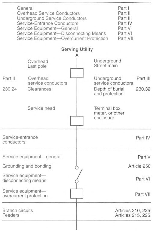
Informational Note No. 1: See Informational Note Figure 230.1.
Informational Note No. 2: See Part V of Article 235 for services over 1000 volts ac or 1500 volts dc, nominal.
Informational Note Figure 230.1 Services.
230.2 Number of Services.
A building or other structure served shall be supplied by only one service unless permitted in 230.2(A) through (D). For the purpose of 230.40, Exception No. 2 only, underground sets of conductors, 1/0 AWG and larger, running to the same location and connected together at their supply end but not connected together at their load end shall be considered to be supplying one service.
(A) Special Conditions.
Additional services shall be permitted to supply the following:
- Fire pumps
- Emergency systems
- Legally required standby systems
- Optional standby systems
- Interconnected electric power production sources
- Systems designed for connection to multiple sources of supply for the purpose of enhanced reliability
(B) Special Occupancies.
By special permission, additional services shall be permitted for either of the following:
- Multiple-occupancy buildings where there is no available space for service equipment accessible to all occupants
- A single building or other structure sufficiently large to make two or more services necessary
(C) Capacity Requirements.
Additional services shall be permitted under any of the following:
- Where the capacity requirements are in excess of 2000 amperes at a supply voltage of 1000 volts or less
- Where the load requirements of a single-phase installation are greater than the serving agency normally supplies through one service
- By special permission
(D) Different Characteristics.
Additional services shall be permitted for different voltages, frequencies, or phases, or for different uses, such as for different rate schedules.
(E) Identification.
Where a building or structure is supplied by more than one service, or any combination of branch circuits, feeders, and services, a permanent plaque or directory shall be installed at each service disconnect location denoting all other services, feeders, and branch circuits supplying that building or structure and the area served by each. See 225.37.
230.3 One Building or Other Structure Not to Be Supplied Through Another.
Service conductors supplying a building or other structure shall not pass through the interior of another building or other structure.
230.6 Conductors Considered Outside the Building.
Conductors shall be considered outside of a building or other structure under any of the following conditions:
- Where installed under not less than 50 mm (2 in.) of concrete beneath a building or other structure
- Where installed within a building or other structure in a raceway that is encased in concrete or brick not less than 50 mm (2 in.) thick
- Where installed in any vault that meets the construction requirements of Part III of Article 450
- Where installed in conduit and under not less than 450 mm (18 in.) of earth beneath a building or other structure
- Where installed within rigid metal conduit (RMC) or intermediate metal conduit (IMC) used to accommodate the clearance requirements in 230.24 and routed directly through an eave but not a wall of a building
230.7 Other Conductors.
Circuit conductors other than service conductors, shall not be installed in the same raceway, cable, handhole enclosure, or underground box as the service conductors.
Exception No. 1: Grounding electrode conductors or supply side bonding jumpers or conductors shall be permitted within service raceways.
Exception No. 2: Load management control conductors having overcurrent protection shall be permitted within service raceways.
230.9 Clearances on Buildings.
(A) Clearances.
Service conductors installed as open conductors or multiconductor cable without an overall outer jacket shall have a clearance of not less than 900 mm (3 ft) from windows that are designed to be opened, doors, porches, balconies, ladders, stairs, fire escapes, or similar locations.
Exception: Conductors run above the top level of a window shall be permitted to be less than the 900 mm (3 ft) requirement.
(B) Vertical Clearance.
The vertical clearance of final spans above, or within 900 mm (3 ft) measured horizontally of platforms, projections, or surfaces that will permit personal contact shall be maintained in accordance with 230.24(B).
(C) Building Openings.
Overhead service conductors shall not be installed beneath openings through which materials may be moved, such as openings in farm and commercial buildings, and shall not be installed where they obstruct entrance to these building openings.
230.10 Vegetation as Support.
Vegetation such as trees shall not be used for support of overhead service conductors or service equipment.
230.22 Insulation or Covering.
Individual conductors shall be insulated or covered.
Exception: The grounded conductor of a multiconductor cable shall be permitted to be bare.
230.23 Size and Ampacity.
(A) General.
Conductors shall have sufficient ampacity to carry the current for the load as calculated in accordance with Parts II through V of Article 220 and shall have adequate mechanical strength.
(B) Minimum Size.
The conductors shall not be smaller than 8 AWG copper or 6 AWG aluminum or copper-clad aluminum.
Exception: Conductors supplying only limited loads of a single branch circuit - such as small polyphase power, controlled water healers, and similar loads - shall not be smaller than 12 AWG hard-drawn copper or equivalent.
230.24 Clearances.
Overhead service conductors shall not be readily accessible and shall comply with 230.24(A) through (E) for services not over 1000 volts, nominal.
(A) Above Roofs.
Conductors shall have a vertical clearance of not less than 2.6 m (8 ft 6 in.) above the roof surface. The vertical clearance above the roof level shall be maintained for a distance of not less than 900 mm (3 ft) in all directions from the edge of the roof.
Exception No. 1: The area above a roof surface subject to pedestrian or vehicular traffic shall have a vertical clearance from the roof surface in accordance with the clearance requirements of 230.24(B).
Exception No. 2: Where the voltage between conductors does not exceed 300 and the roof has a slope of 100 mm in 300 mm (4 in. in 12 in.) or greater, a reduction in clearance to 900 mm (3 ft) shall be permitted.
Exception No. 3: Where the voltage between conductors does not exceed 300, a reduction in clearance above only the overhanging portion of the roof to not less than 450 mm (18 in.) shall be permitted if (1) not more than 1.8 m (6 ft) of overhead service conductors, 1.2 m (4 ft) horizontally, pass above the roof overhang, and (2) they are terminated at a through-the-roof raceway or approved support.
Informational Note: Sec 230.28 for mast supports.
Exception No. 4: The requirement for maintaining the vertical clearance 900 mm (3 ft) from the edge of the roof shall not apply to the final conductor span where the service drop or overhead service conductors are attached to the side of a building.
(B) Vertical Clearance for Overhead Service Conductors.
Overhead service conductors, where not in excess of 1000 volts, nominal, shall have the following minimum clearance from final grade:
- 3.0 m (10 ft) - at the electrical service entrance to buildings, also at the lowest point of the drip loop of the building electrical entrance, and above areas or sidewalks accessible only to pedestrians, measured from final grade or other accessible surface only for overhead service conductors supported on and cabled together with a grounded bare messenger where the voltage does not exceed 150 volts to ground
- 3.7 m (12 ft) - over residential property and driveways, and those commercial areas not subject to truck traffic where the voltage does not exceed 300 volts to ground
- 4.5 m (15 ft) - for those areas listed in the 3.7 m (12 ft) classification where the voltage exceeds 300 volts to ground
- 5.5 m (18 ft) - over public streets, alleys, roads, parking areas subject to truck traffic, driveways on other than residential property, and other land such as cultivated, grazing, forest, and orchard
- 7.5 m (241/2 ft) over tracks of railroads
230.26 Point of Attachment.
The point of attachment of the overhead service conductors to a building or other structure shall provide the minimum clearances as specified in 230.9 and 230.24. In no case shall this point of attachment be less than 3.0 m (10 ft) above finished grade.
230.27 Means of Attachment.
Multiconductor cables used for overhead service conductors shall be attached to buildings or other structures by fittings identified for use with service conductors. Open conductors shall be attached to fittings identified for use with service conductors or to noncombustible, nonabsorbent insulators securely attached to the building or other structure.
230.28 Service Masts as Supports.
Only power service-drop or overhead service conductors shall be permitted to be attached to a service mast. Service masts used for the support of service-drop or overhead service conductors shall be installed in accordance with 230.28(A) and (B).
(A) Strength.
The service mast shall be of adequate strength or be supported by braces or guy wires to withstand safely the strain imposed by the service-drop or overhead service conductors. Hubs intended for use with a conduit that serves as a service mast shall be identified for use with service-entrance equipment.
(B) Attachment.
Service-drop or overhead service conductors shall not be attached to a service mast between a weatherhead or the end of the conduit and a coupling, where the coupling is located above the last point of securement to the building or other structure or is located above the building or other structure.
230.29 Supports Over Buildings.
Service conductors passing over a roof shall be securely supported by substantial structures. For a grounded system, where the substantial structure is metal, it shall be bonded by means of a bonding jumper and listed connector to the grounded overhead service conductor. Where practicable, such supports shall be independent of the building.
230.30 Installation.
(A) Insulation.
Underground service conductors shall be insulated for the applied voltage.
Exception: A grounded conductor shall be permitted to be uninsulated as follows:
(1) Bare copper used in a raceway
(2) Bare copper for direct burial where bare copper is approved for the soil conditions
(3) Bare copper for direct burial without regard to soil conditions where part of a cable assembly identified for underground use
(4) Aluminum or copper-clad aluminum without individual insulation or covering where part of a cable assembly identified for underground use in a raceway or for direct burial
(B) Wiring Methods.
Underground service conductors shall be installed in accordance with the applicable requirements of this Code covering the type of wiring method used and shall be limited to the following methods:
- RMC conduit
- IMC conduit
- Type NUCC conduit
- HDPE conduit
- PVC conduit
- RTRC conduit
- Type IGS cable
- Type USE conductors or cables
- Type MV or Type MC cable identified for direct burial applications
- Type MI cable where suitably protected against physical damage and corrosive conditions
- Type TC-ER cable where identified for service entrance use and direct burial applications
230.31 Size and Ampacity.
(A) General.
Underground service conductors shall have sufficient ampacity to carry the current for the load as calculated in accordance with Parts II through V of Article 220.
(B) Minimum Size.
The conductors shall not be smaller than 8 AWG copper or 6 AWG aluminum or copper-clad aluminum.
Exception: Conductors supplying only limited loads of a single branch circuit - such as small polyphase power, controlled water heaters, and similar loads - shall not be smaller than 12 AWG copper or 10 AWG aluminum or copper-clad aluminum.
230.32 Protection Against Damage.
Underground service conductors shall be protected against damage in accordance with 300.5. Service conductors entering a building or other structure shall be installed in accordance with 230.6 or protected by a raceway wiring method identified in 230.43.
230.40 Number of Service-Entrance Conductor Sets.
Each service drop, set of overhead service conductors, set of underground service conductors, or service lateral shall supply only one set of service-entrance conductors.
Exception No. 1: A building with more than one occupancy shall be permitted to have one set of service-entrance conductors for each service, as permitted in 230.2, run to each occupancy or group of occupancies. If the number of service disconnect locations for any given classification of service does not exceed six, the requirements of 230.2(E) shall apply at each location. If the number of service disconnect locations exceeds six for any given supply classification, the following conditions shall apply:
(1) All service disconnect locations for all supply characteristics, together with any branch circuit or feeder supply sources, shall be clearly described using graphics or text, or both, on one or more plaques
(2) The plaques shall be located in an approved, readily accessible location(s) on the building or structure served and as near as practicable to the point(s) of attachment or entry(ies) for each service drop or service lateral and for each set of overhead or underground service conductors.
Exception No. 2: Where two to six service disconnecting means in separate enclosures are grouped at one location and supply separate loads from one service drop, set of overhead service conductors, set of underground service conductors, or service lateral, one set of service-entrance conductors shall be permitted to supply each or several such service equipment enclosures.
Exception No. 3: A one-family dwelling unit and its accessory structures shall be permitted to have one set of service-entrance conductors run to each from a single service drop, set of overhead service conductors, set of underground service conductors, or service lateral.
Exception No. 4: Two-family dwellings, multifamily dwellings, and multiple occupancy buildings shall be permitted to have one set of service-entrance conductors installed to supply the circuits covered in 210.25.
Exception No. 5: One set of service-entrance conductors connected to the supply side of the normal service disconnecting means shall be permitted to supply each or several systems covered by 230.82(5) or 230.82(6).
230.41 Insulation of Service-Entrance Conductors.
Service-entrance conductors entering or on the exterior of buildings or other structures shall be insulated.
Exception: A grounded conductor shall be permitted to be uninsulated as follows:
(2) Bare copper for direct burial where bare copper is approved for the soil conditions
(3) Bare copper for direct burial without regard to soil conditions where part of a cable assembly identified for underground use
(4) Aluminum or copper-clad aluminum without individual insulation or covering where part of a cable assembly or identified for underground use in a raceway, or for direct burial
(5) Bare conductors used in an auxiliary gutter
230.42 Minimum Size and Ampacity.
(A) General.
Service-entrance conductors shall have an ampacity of not less than the maximum load to be served. Conductors shall be sized not less than the largest of 230.42(A)(1) or (A)(2). Loads shall be determined in accordance with Part III, IV, or V of Article 220, as applicable. Ampacity shall be determined from 310.14 and shall comply with 110.14(C). The maximum current of busways shall be that value for which the busway has been listed or labeled.
(1) Continuous and Noncontinuous Loads.
Where the service-entrance conductors supply continuous loads or any combination of noncontinuous and continuous loads, the minimum service-entrance conductor size shall have an ampacity not less than the sum of the noncontinuous loads plus 125 percent of continuous loads.
Exception No. 1: Grounded conductors that are not connected to an overcurrent device shall be permitted to be sized at 100 percent of the sum of the continuous and noncontinuous load.
Exception No. 2: The sum of the noncontinuous load and the continuous load if the service-entrance conductors terminate in an overcurrent device where both the overcurrent device and its assembly are listed for operation at 100 percent of their rating shall be permitted.
(B) Specific Installations.
In addition to the requirements of 230.42(A), the minimum ampacity for ungrounded conductors for specific installations shall not be less than the rating of the service disconnecting means specified in 230.79(A) through (D).
230.43 Wiring Methods for 1000 Volts, Nominal, or Less.
Service-entrance conductors shall be installed in accordance with the applicable requirements of this Code covering the type of wiring method used and shall be limited to the following methods:
- Open wiring on insulators
- Type IGS cable
- Rigid metal conduit (RMC)
- Intermediate metal conduit (IMC)
- Electrical metallic tubing (EMT)
- Electrical nonmetallic tubing
- Service-entrance cables
- Wireways
- Busways
- Auxiliary gutters
- Rigid polyvinyl chloride conduit (PVC)
- Cablebus
- Type MC cable
- Mineral-insulated, metal-sheathed cable, Type MI
- Flexible metal conduit (FMC) not over 1.8 m (6 ft) long or liquidtight flexible metal conduit (LFMC) not over 1.8 m (6 ft) long between a raceway, or between a raceway and service equipment, with a supply-side bonding jumper routed with the flexible metal conduit (FMC) or the liquidtight flexible metal conduit (LFMC) according to 250.102(A), (B), (C), and (E)
- Liquidtight flexible nonmetallic conduit (LFNC)
- High density polyethylene conduit (HDPE)
- Nonmetallic underground conduit with conductors (NUCC)
- Reinforced thermosetting resin conduit (RTRC)
- Type TC-ER cable where identified for use as service entrance conductors
- Flexible bus systems
230.44 Cable Trays.
Cable tray systems shall be permitted to support service-entrance conductors. Cable trays used to support service-entrance conductors shall contain only service-entrance conductors and shall be limited to the following methods:
- Type SE cable
- Type MC cable
- Type MI cable
- Type IGS cable
- Single conductors 1/0 and larger that are listed for use in cable tray
- Type TC-ER cable
Such cable trays shall be identified with permanently affixed labels with the wording "Service-Entrance Conductors." The labels shall be located so as to be visible after installation with a spacing not to exceed 3 m (10 ft) so that the service-entrance conductors are able to be readily traced through the entire length of the cable tray.
Exception: Conductors, other than service-entrance conductors, shall be permitted to be installed in a cable tray with service-entrance conductors, provided a solid fixed barrier identified for use with the cable tray is installed to separate the service-entrance conductors from other conductors installed in the cable tray.
230.46 Spliced and Tapped Conductors.
Service-entrance conductors shall be permitted to be spliced or tapped in accordance with 110.14, 300.5(E), 300.13, and 300.15. Power distribution blocks, pressure connectors, and devices for splices and taps shall be listed. Power distribution blocks installed on service conductors shall be marked "suitable for use on the line side of the service equipment" or equivalent.
Pressure connectors and devices for splices and taps installed on service conductors shall be marked "suitable for use on the line side of the service equipment" or equivalent.
230.50 Protection Against Physical Damage.
(A) Underground Service-Entrance Conductors.
Underground service-entrance conductors shall be protected against physical damage in accordance with 300.5.
(B) All Other Service-Entrance Conductors.
All other service-entrance conductors, other than underground service entrance conductors, shall be protected against physical damage as specified in 230.50(B)(1) or (B)(2).
(2) Other Than Service-Entrance Cables.
Individual open conductors and cables, other than service-entrance cables, shall not be installed within 3.0 m (10 ft) of grade level or where exposed to physical damage.
Exception: Type MI and Type MC cable shall be permitted within 3.0 m (10 ft) of grade level where not exposed to physical damage or where protected in accordance with 300.5(D).
230.51 Mounting Supports.
Service-entrance cables or individual open service-entrance conductors shall be supported as specified in 230.51 (A), (B), or (C).
(B) Other Cables.
Cables that are not approved for mounting in contact with a building or other structure shall be mounted on insulating supports installed at intervals not exceeding 4.5 m (15 ft) and in a manner that maintains a clearance of not less than 50 mm (2 in.) from the surface over which they pass.
(C) Individual Open Conductors.
Individual open conductors shall be installed in accordance with Table 230.51(C). Where exposed to the weather, the conductors shall be mounted on insulators or on insulating supports attached to racks, brackets, or other approved means. Where not exposed to the weather, the conductors shall be mounted on glass or porcelain knobs.
Table 230.51(C) Supports.
| Maximum Volts | Maximum Distance Between Supports | Minimum Clearance | ||||
|---|---|---|---|---|---|---|
| Between Conductors | From Surface | |||||
| m | ft | mm | in. | mm | in. | |
| 1000 | 2.7 | 9 | 150 | 6 | 50 | 2 |
| 1000 | 4.5 | 15 | 300 | 12 | 50 | 2 |
| 300 | 1.4 | 41/2 | 75 | 3 | 50 | 2 |
| 1000* | 1.4* | 41/2* | 65* | 21/2* | 25* | 1* |
*Where not exposed to weather.
230.52 Individual Conductors Entering Buildings or Other Structures.
Where individual open conductors enter a building or other structure, they shall enter through roof bushings or through the wall in an upward slant through individual, noncombustible, nonabsorbent insulating tubes. Drip loops shall be formed on the conductors before they enter the tubes.
230.53 Raceways to Drain.
Where exposed to the weather, raceways enclosing service-entrance conductors shall be listed or approved for use in wet locations and arranged to drain. Where embedded in masonry, raceways shall be arranged to drain.
230.54 Overhead Service Locations.
(A) Service Head.
Service raceways shall be equipped with a service head at the point of connection to service-drop or overhead service conductors. The service head shall be listed for use in wet locations.
(C) Service Heads and Goosenecks Above Service-Drop or Overhead Service Attachment.
Service heads on raceways or service-entrance cables and goosenecks in service-entrance cables shall be located above the point of attachment of the service-drop or overhead service conductors to the building or other structure.
(D) Secured.
Service-entrance cables shall be held securely in place.
(F) Drip Loops.
Drip loops shall be formed on individual conductors. To prevent the entrance of moisture, service-entrance conductors shall be connected to the service-drop or overhead service conductors either (1) below the level of the service head or (2) below the level of the termination of the service-entrance cable sheath.
(G) Arranged That Water Will Not Enter Service Raceway or Equipment.
Service-entrance and overhead service conductors shall be arranged so that water will not enter service raceway or equipment.
230.56 Service Conductor With the Higher Voltage to Ground.
On a 4-wire, delta-connected service where the midpoint of one phase winding is grounded, the service conductor having the higher phase voltage to ground shall be durably and permanently marked by an outer finish that is orange in color, or by other effective means, at each termination or junction point.
230.62 Service Equipment - Enclosed or Guarded.
Energized parts of service equipment shall be enclosed as specified in 230.62(A) or guarded as specified in 230.62(B).
(A) Enclosed.
Energized parts shall be enclosed so that they will not be exposed to accidental contact or shall be guarded as in 230.62(B).
(B) Guarded.
Energized parts that are not enclosed shall be installed on a switchboard, panelboard, or control board and guarded in accordance with 110.18 and 110.27. Where energized parts are guarded as provided in 110.27(A)(1) and (A)(2), a means for locking or sealing doors providing access to energized parts shall be provided.
(C) Barriers.
Barriers shall be placed in service equipment such that no uninsulated, ungrounded service busbar or service terminal is exposed to inadvertent contact by persons or maintenance equipment while servicing load terminations with the service disconnect in the open position.
230.66 Marking.
(A) General.
Service equipment rated at 1000 volts or less shall be marked to identify it as being suitable for use as service equipment. All service equipment shall be listed or field evaluated.
(B) Meter Sockets.
Meter sockets shall not be considered service equipment but shall be listed and rated for the voltage and current rating of the service.
Exception: Meter sockets supplied by and under the exclusive control of an electric utility shall not be required to be listed.
230.67 Surge Protection.
(A) Surge-Protective Device.
All services supplying the following occupancies shall be provided with a surge-protective device (SPD):
- Dwelling units
- Dormitory units
- Guest rooms and guest suites of hotels and motels
- Areas of nursing homes and limited-care facilities used exclusively as patient sleeping rooms
Informational Note: See 517.10(B)(2).
(B) Location.
The SPD shall be an integral part of the service equipment or shall be located immediately adjacent thereto.
Exception: The SPD shall not be required to be located at the service equipment as required in 230.67(B) if located at each next level distribution equipment downstream toward the load.
(E) Ratings.
SPDs shall have a nominal discharge current rating (In) of not less than 10kA.
230.70 General.
Means shall be provided to disconnect all ungrounded conductors in a building or other structure from the service conductors.
(A) Location.
The service disconnecting means shall be installed in accordance with 230.70(A)(1), (A)(2), and (A)(3).
(1) Readily Accessible Location.
The service disconnecting means shall be installed at a readily accessible location either outside of a building or structure or inside nearest the point of entrance of the service conductors.
(3) Remote Control.
Where a remote control device(s) is used to actuate the service disconnecting means, the service disconnecting means shall be located in accordance with 230.70(A)(1).
(C) Suitable for Use.
Each service disconnecting means shall be suitable for the prevailing conditions. Service equipment installed in hazardous (classified) locations shall comply with the hazardous location requirements.
230.71 Maximum Number of Disconnects.
(A) General.
For the purpose of this section, disconnecting means installed as part of listed equipment and used solely for the following shall not be considered a service disconnecting means:
- Power monitoring equipment
- Surge-protective device(s)
- Control circuit of the ground-fault protection system
- Power-operable service disconnecting means
(B) Two to Six Service Disconnecting Means.
Two to six service disconnects shall be permitted for each service permitted by 230.2 or for each set of service-entrance conductors permitted by 230.40, Exception No. 1, 3, 4, or 5. The two to six service disconnecting means shall be permitted to consist of a combination of any of the following:
- Separate enclosures with a main service disconnecting means in each enclosure
- Panelboards with a main service disconnecting means in each panelboard enclosure
- Switchboard(s) where there is only one service disconnect in each separate vertical section with barriers provided between each vertical section to maintain the inadvertent contact protection required in 230.62 based on access from the adjacent section(s)
- Service disconnects in switchgear, transfer switches, or metering centers where each disconnect is located in a separate compartment
- Metering centers with a main service disconnecting means in each metering center
- Motor control center(s) where there is only one service disconnect in a motor control center unit and a maximum of two service disconnects provided in a single motor control center with barriers provided between each motor control center unit or compartment containing a service disconnect to maintain the inadvertent contact protection required in 230.62 based on access from adjacent motor control center unit(s) or compartment(s)
Exception to (2), (3), (4), (5), and (6): Existing service equipment, installed in compliance with previous editions of this Code that permitted multiple service disconnecting means in a single enclosure, section, or compartment, shall be permitted to contain a maximum of six service disconnecting means.
Informational Note No. 1: See UL 67, Standard for Panelboards, for information on metering centers.
Informational Note No. 2: Examples of separate enclosures with a main service disconnecting means in each enclosure include but are not limited to motor control centers, fused disconnects, and circuit breaker enclosures.
Informational Note No. 3: Transfer switches are provided with one service disconnect or multiple service disconnects in separate compartments.
230.72 Grouping of Disconnects.
(A) General.
The two to six disconnects, if permitted in 230.71, shall be grouped. Each disconnect shall be marked to indicate the load served.
Exception: One of the two to six service disconnecting means permitted in 230.71, where used only for a water pump also intended to provide fire protection, shall be permitted to be located remote from the other disconnecting means. If remotely installed in accordance with this exception, a plaque shall be posted at the location of the remaining grouped disconnects denoting its location.
(B) Additional Service Disconnecting Means.
The one or more additional service disconnecting means for fire pumps, emergency systems, legally required standby, or optional standby services permitted by 230.2 shall be installed remote from the one to six service disconnecting means for normal service to minimize the possibility of simultaneous interruption of supply.
(C) Access to Occupants.
In a multiple-occupancy building, each occupant shall have access to the occupant's service disconnecting means.
Exception: In a multiple-occupancy building where electric service and electrical maintenance are provided by the building management and where these are under continuous building management supervision, the service disconnecting means supplying more than one occupancy shall be permitted to be accessible to authorized management personnel only.
230.74 Simultaneous Opening of Poles.
Each service disconnect shall simultaneously disconnect all ungrounded service conductors that it controls from the premises wiring system.
230.75 Disconnection of Grounded Conductor.
Where the service disconnecting means does not disconnect the grounded conductor from the premises wiring, other means shall be provided for this purpose in the service equipment. A terminal or bus to which all grounded conductors can be attached by means of pressure connectors shall be permitted for this purpose. In a multisection switchboard or switchgear, disconnects for the grounded conductor shall be permitted to be in any section of the switchboard or switchgear, if the switchboard or switchgear section is marked to indicate a grounded conductor disconnect is located within.
Informational Note: In switchgear or multisection switchboards, the disconnecting means provided for the grounded conductor is typically identified as a neutral disconnect link and is typically located in the bus to which the service grounded conductor is connected.
230.76 Manually or Power Operable.
The service disconnecting means for ungrounded service conductors shall consist of one of the following:
- A manually operable switch or circuit breaker equipped with a handle or other suitable operating means
- A power-operated switch or circuit breaker, provided the switch or circuit breaker can be opened by hand in the event of a power supply failure
230.77 Indicating.
The service disconnecting means shall plainly indicate whether it is in the open (off) or closed (on) position.
230.79 Rating of Service Disconnecting Means.
The service disconnecting means shall have a rating not less than the calculated load to be carried, determined in accordance with Part III, IV, or V of Article 220, as applicable. In no case shall the rating be lower than specified in 230.79(A), (B), (C), or (D).
(A) One-Circuit Installations.
For installations to supply only limited loads of a single branch circuit, the service disconnecting means shall have a rating of not less than 15 amperes.
(B) Two-Circuit Installations.
For installations consisting of not more than two 2-wire branch circuits, the service disconnecting means shall have a rating of not less than 30 amperes.
(C) One-Family Dwellings.
For a one-family dwelling, the service disconnecting means shall have a rating of not less than 100 amperes, 3-wire.
(D) All Others.
For all other installations, the service disconnecting means shall have a rating of not less than 60 amperes.
230.80 Combined Rating of Disconnects.
Where the service disconnecting means consists of more than one switch or circuit breaker, as permitted by 230.71, the combined ratings of all the switches or circuit breakers used shall not be less than the rating required by 230.79.
230.81 Connection to Terminals.
The service conductors shall be connected to the service disconnecting means by pressure connectors, clamps, or other approved means. Connections that depend on solder shall not be used.
230.82 Equipment Connected to the Supply Side of Service Disconnect.
Only the following equipment shall be permitted to be connected to the supply side of the service disconnecting means:
- Cable limiters.
- Meters and meter sockets nominally rated not in excess of 1000 volts, if all metal housings and service enclosures are grounded in accordance with Part VII and bonded in accordance with Part V of Article 250.
- Meter disconnect switches nominally rated not in excess of 1000 volts that have a short-circuit current rating equal to or greater than the available fault current, if all metal housings and service enclosures are grounded in accordance with Part VII and bonded in accordance with Part V of Article 250. A meter disconnect switch shall be capable of interrupting the load served. A meter disconnect shall be legibly field marked on its exterior in a manner suitable for the environment as follows:METER DISCONNECT NOT SERVICE EQUIPMENT
- Instrument transformers (current and voltage), impedance shunts, load management devices, surge arresters, and Type 1 surge-protective devices.
- Conductors used to supply energy management systems, circuits for standby power systems, fire pump equipment, and fire and sprinkler alarms, if provided with service equipment and installed in accordance with requirements for service-entrance conductors.
- Solar photovoltaic systems, fuel cell systems, wind electric systems, energy storage systems, or interconnected electric power production sources, if provided with a disconnecting means listed as suitable for use as service equipment, and overcurrent protection as specified in Part VII of Article 230.
- Control circuits for power-operable service disconnecting means, if suitable overcurrent protection and disconnecting means are provided.
- Ground-fault protection systems or Type 2 surge-protective devices, where installed as part of listed equipment, if suitable overcurrent protection and disconnecting means are provided.
- Connections used only to supply listed communications equipment under the exclusive control of the serving electric utility, if suitable overcurrent protection and disconnecting means are provided. For installations of equipment by the serving electric utility, a disconnecting means is not required if the supply is installed as part of a meter socket, such that access can only be gained with the meter removed.
- Emergency disconnects in accordance with 230.85(B)(2) and (B)(3), if all metal housings and enclosures are grounded in accordance with Part VII and bonded in accordance with Part V of Article 250.
- Meter-mounted transfer switches nominally rated not in excess of 1000 volts that have a short-circuit current rating equal to or greater than the available fault current. A meter-mounted transfer switch shall be listed and be capable of transferring the load served. A meter-mounted transfer switch shall be marked on its exterior with both of the following:
- Meter-mounted transfer switch
- Not service equipment
- Control power circuits for protective relays where installed as part of listed equipment, if overcurrent protection and disconnecting means are provided.
230.85 Emergency Disconnects.
(A) General.
(1) Location.
The disconnecting means shall be installed in a readily accessible outdoor location on or within sight of the dwelling unit.
Exception: Where the requirements of 225.41 are met, this section shall not apply.
(2) Rating.
The disconnecting means shall have a short-circuit current rating equal to or greater than the available fault current.
(B) Disconnects.
Each disconnect shall be one of the following:
- Service disconnect
- A meter disconnect integral to the meter mounting equipment not marked as suitable only for use as service equipment installed in accordance with 230.82
- Other listed disconnect switch or circuit breaker that is marked suitable for use as service equipment, but not marked as suitable only for use as service equipment, installed on the supply side of each service disconnect
Informational Note 1: Conductors between the emergency disconnect and the service disconnect in 230.85(2) and 230.85(3) are service conductors.
Informational Note 2: Equipment marked "Suitable only for use as service equipment" includes the factory marking "Service Disconnect".
(C) Replacement.
(D) Identification of Other Isolation Disconnects.
Where equipment for isolation of other energy source systems is not located adjacent to the emergency disconnect required by this section, a plaque or directory identifying the location of all equipment for isolation of other energy sources shall be located adjacent to the disconnecting means required by this section.
(E) Marking.
(1) Marking Text.
The disconnecting means shall marked as follows:
- Service disconnectEMERGENCY DISCONNECT, SERVICE DISCONNECT
- Meter disconnects installed in accordance with 230.82(3) and marked as follows:EMERGENCY DISCONNECT, METER DISCONNECT, NOT SERVICE EQUIPMENT
- Other listed disconnect switches or circuit breakers on the supply side of each service disconnect that are marked suitable for use as service equipment and marked as follows:
EMERGENCY DISCONNECT, NOT SERVICE EQUIPMENT
230.90 Where Required.
(A) Ungrounded Conductor.
Such protection shall be provided by an overcurrent device in series with each ungrounded service conductor that has a rating or setting not higher than the ampacity of the conductor. A set of fuses shall be considered all the fuses required to protect all the ungrounded conductors of a circuit. Single-pole circuit breakers, grouped in accordance with 230.71(B), shall be considered as one protective device.
Exception No. 1: For motor-starting currents, ratings that comply with 430.52, 430.62, and 430.63 shall be permitted.
Exception No. 2: Fuses and circuit breakers with a rating or setting that complies with 240.4(B) or (C) and 240.6 shall be permitted.
Exception No. 3: Two to six circuit breakers or sets of fuses shall be permitted as the overcurrent device to provide the overload protection. The sum of the ratings of the circuit breakers or fuses shall be permitted to exceed the ampacity of the service conductors, provided the calculated load does not exceed the ampacity of the service conductors.
Exception No. 4: Overload protection for fire pump supply conductors shall comply with 695.4(B)(2)(a).
Exception No. 5: Overload protection in accordance with the conductor ampacities of 310.12 shall be permitted for single-phase dwelling services.
(B) Not in Grounded Conductor.
No overcurrent device shall be inserted in a grounded service conductor except a circuit breaker that simultaneously opens all conductors of the circuit.
230.91 Location.
The service overcurrent device shall be an integral part of the service disconnecting means or shall be located immediately adjacent thereto. Where fuses are used as the service overcurrent device, the disconnecting means shall be located ahead of the supply side of the fuses.
230.92 Locked Service Overcurrent Devices.
Where the service overcurrent devices are locked or sealed or are not readily accessible to the occupant, branch-circuit or feeder overcurrent devices shall be installed on the load side, shall be mounted in a readily accessible location, and shall be of lower ampere rating than the service overcurrent device.
230.93 Protection of Specific Circuits.
Where necessary to prevent tampering, an automatic overcurrent device that protects service conductors supplying only a specific load, such as a water heater, shall be permitted to be locked or sealed where located so as to be accessible.
230.94 Relative Location of Overcurrent Device and Other Service Equipment.
The overcurrent device shall protect all circuits and devices.
Exception No. 1: The service switch shall be permitted on the supply side.
Exception No. 2: High-impedance shunt circuits, surge arresters, Type 1 surge-protective devices, surge-protective capacitors, and instrument transformers (current and voltage) shall be permitted to be connected and installed on the supply side of the service disconnecting means as permitted by 230.82.
Exception No. 3: Circuits for load management devices shall be permitted to be connected on the supply side of the service overcurrent device where separately provided with overcurrent protection.
Exception No. 4: Circuits used only for the operation of fire alarm, other protective signaling systems, or the supply to fire pump equipment shall be permitted to be connected on the supply side of the service overcurrent device where separately provided with overcurrent protection.
Exception No. 5: Meters nominally rated not in excess of 600 volts shall be permitted, provided all metal housings and service enclosures are grounded.
Exception No. 6: Where service equipment is power operable, the control circuit shall be permitted to be connected ahead of the service equipment if suitable overcurrent protection and disconnecting means are provided.
230.95 Ground-Fault Protection of Equipment.
Ground-fault protection of equipment shall be provided for solidly grounded wye electric services of more than 150 volts to ground but not exceeding 1000 volts phase-to-phase for each service disconnect rated 1000 amperes or more. The grounded conductor for the solidly grounded wye system shall be connected directly to ground through a grounding electrode system, as specified in 250.50, without inserting any resistor or impedance device.
The rating of the service disconnect shall be considered to be the rating of the largest fuse that can be installed or the highest continuous current trip setting for which the actual overcurrent device installed in a circuit breaker is rated or can be adjusted.
Exception: The ground-fault protection provisions of this section shall not apply to a service disconnect for a continuous industrial process where a nonorderly shutdown will introduce additional or increased hazards.
(A) Setting.
The ground-fault protection system shall operate to cause the service disconnect to open all ungrounded conductors of the faulted circuit. The maximum setting of the ground-fault protection shall be 1200 amperes, and the maximum time delay shall be one second for ground-fault currents equal to or greater than 3000 amperes.
(B) Fuses.
If a switch and fuse combination is used, the fuses employed shall be capable of interrupting any current higher than the interrupting capacity of the switch during a time that the ground-fault protective system will not cause the switch to open.
(C) Performance Testing.
The ground-fault protection system shall be performance tested when first installed on site. This testing shall be conducted by a qualified person(s) using a test process of primary current injection, in accordance with instructions that shall be provided with the equipment. A written record of this testing shall be made and shall be available to the authority having jurisdiction.
Informational Note No. 1: Ground-fault protection that functions to open the service disconnect affords no protection from faults on the line side of the protective element. It serves only to limit damage to conductors and equipment on the load side in the event of an arcing ground fault on the load side of the protective element.
Informational Note No. 2: This added protective equipment at the service equipment could make it necessary to review the overall wiring system for proper selective overcurrent protection coordination. Additional installations of ground-fault protective equipment might be needed on feeders and branch circuits where maximum continuity of electric service is necessary.
Informational Note No. 3: Where ground-fault protection is provided for the service disconnect and interconnection is made with another supply system by a transfer device, means or devices could be needed to ensure proper ground-fault sensing by the ground-fault protection equipment.
Informational Note No. 4: See 517.17(A) for information on where an additional step of ground-fault protection is required for hospitals and other buildings with critical areas or life support equipment.
Article 235
Branch Circuits, Feeders, and Services Over 1000 Volts AC, 1500 Volts DC, Nominal
235.3 Other Articles for Specific-Purpose Branch Circuits.
Table 235.3 References for Specific Equipment and Applications Not Located in Chapters 5, 6, and 7.
| Equipment | Article | Section |
|---|---|---|
| Air-conditioning and refrigerating equipment | 440.6, 440.31, and 440.32 | |
| Busways | 368.17 | |
| Central heating equipment other than fixed electric space-heating equipment | 422.12 | |
| Fixed electric heating equipment for pipelines and vessels | 427.4 | |
| Fixed electric space-heating equipment | 424.4 | |
| Fixed outdoor electrical deicing and snow-melting equipment | 426.4 | |
| Infrared lamp industrial heating equipment | 422.48 and 424.3 | |
| Motors, motor circuits, and controllers | 430 |
235.5 Conductor Identification for Branch Circuits.
(C) Ungrounded Conductors.
(1) Branch Circuits Supplied From More Than One Nominal Voltage System.
Where the premises wiring system has branch circuits supplied from more than one nominal voltage system, each ungrounded conductor of a branch circuit shall be identified by phase or line and by nominal system voltage at all termination, connection, and splice points in accordance with 235.5(C)(1)(a) and (C)(1)(b). Different systems within the same premises that have the same nominal voltage shall be permitted to use the same identification.
- Means of Identification. The means of identification shall be permitted to be by separate color coding, marking tape, tagging, or other approved means.
- Posting of Identification Means. The method used for conductors originating within each branch-circuit panelboard or similar branch-circuit distribution equipment shall be documented in a manner that is readily available or shall be permanently posted at each branch-circuit panelboard or similar branch-circuit distribution equipment. The label shall be of sufficient durability to withstand the environment involved and shall not be handwritten.
Exception: In existing installations where a voltage system(s) already exists and a different voltage system is being added, it shall be permissible to mark only the new system voltage. Existing unidentified systems shall not be required to be identified at each termination, connection, and splice point in accordance with 235.5(C)(1)(a) and (C)(1)(b). Labeling shall be required at each voltage system distribution equipment to identify that only one voltage system has been marked for a new system(s). The new system label(s) shall include the words "other unidentified systems exist on the premises."
(2) Branch Circuits Supplied From Direct-Current Systems.
Where a branch circuit is supplied from a dc system operating at more than 1500 volts, each ungrounded conductor of 4 AWG or larger shall be identified by polarity at all termination, connection, and splice points by marking tape, tagging, or other approved means and each ungrounded conductor of 6 AWG or smaller shall be identified by polarity at all termination, connection, and splice points in compliance with 235.5(C)(2)(a) and (C)(2)(b). The identification methods used for conductors originating within each branch-circuit panelboard or similar branch-circuit distribution equipment shall be documented in a manner that is readily available or be permanently posted at each branch-circuit panelboard or similar branch-circuit distribution equipment.
- Positive Polarity, Sizes 6 AWG or Smaller. Where the positive polarity of a dc system does not serve as the connection point for the grounded conductor, each positive ungrounded conductor shall be identified by one of the following means:
- A continuous red outer finish
- A continuous red stripe durably marked along the conductor's entire length on insulation of a color other than green, white, gray, or black
- Imprinted plus signs (+) or the word POSITIVE or POS durably marked on insulation of a color other than green, white, gray, or black and repeated at intervals not exceeding 610 mm (24 in.) in accordance with 310.8(B)
- An approved permanent marking means such as sleeving or shrink-tubing that is suitable for the conductor size, at all termination, connection, and splice points, with imprinted plus signs (+) or the word POSITIVE or POS durably marked on insulation of a color other than green, white, gray, or black
- Negative Polarity, Sizes 6 AWG or Smaller. Where the negative polarity of a dc system does not serve as the connection point for the grounded conductor, each negative ungrounded conductor shall be identified by one of the following means:
- A continuous black outer finish
- A continuous black stripe durably marked along the conductor's entire length on insulation of a color other than green, white, gray, or red
- Imprinted minus signs (—) or the word NEGATIVE or NEG durably marked on insulation of a color other than green, white, gray, or red and repeated at intervals not exceeding 610 mm (24 in.) in accordance with 310.8(B)
- An approved permanent marking means such as sleeving or shrink-tubing that is suitable for the conductor size, at all termination, connection, and splice points, with imprinted minus signs (—) or the word NEGATIVE or NEG durably marked on insulation of a color other than green, white, gray, or red
235.6 Branch-Circuit Voltage Limitations Over 1000 Volts AC or 1500 Volts DC, Nominal, Between Conductors.
Circuits exceeding 1000 volts ac or 1500 volts dc, nominal, between conductors shall be permitted to supply utilization equipment in installations where conditions of maintenance and supervision ensure that only qualified persons service the installation.
235.9 Circuits Derived From Autotransformers.
Branch circuits shall not be derived from autotransformers unless the circuit supplied has a grounded conductor that is electrically connected to a grounded conductor of the system supplying the autotransformer.
235.10 Ungrounded Conductors Tapped From Grounded Systems.
Two-wire dc circuits and ac circuits of two or more ungrounded conductors shall be permitted to be tapped from the ungrounded conductors of circuits that have a grounded neutral conductor. Switching devices in each tapped circuit shall have a pole in each ungrounded conductor. All poles of multipole switching devices shall manually switch together where such switching devices also serve as a disconnecting means as required by the following sections:
235.11 Branch Circuits Required.
The minimum number of branch circuits shall be determined from the total calculated load and the size or rating of the circuits used. In all installations, the number of circuits shall be sufficient to supply the load served.
235.18 Rating.
Branch circuits recognized by this article shall be rated in accordance with the maximum permitted ampere rating or setting of the overcurrent device. Where conductors of higher ampacity are used for any reason, the ampere rating or setting of the specified overcurrent device shall determine the circuit rating.
235.19 Conductors - Minimum Ampacity and Size.
The ampacity of conductors shall be in accordance with 310.14 and 315.60, as applicable. Branch-circuit conductors shall be sized in accordance with 235.19(A) or (B).
(A) General.
The ampacity of branch-circuit conductors shall not be less than 125 percent of the designed potential load of utilization equipment that will be operated simultaneously.
(B) Supervised Installations.
For supervised installations, branch-circuit conductor sizing shall be permitted to be determined by qualified persons under engineering supervision. Supervised installations are defined as those portions of a facility where both of the following conditions are met:
- Conditions of design and installation are provided under engineering supervision.
- Qualified persons with documented training and experience in over 1000-volt ac or 1500-volt dc systems provide maintenance, monitoring, and servicing of the system.
235.20 Overcurrent Protection.
Branch-circuit conductors and equipment shall be protected by overcurrent protective devices that have a rating or setting that complies with 235.20(A) through (C).
(A) Continuous and Noncontinuous Loads.
Where a branch circuit supplies continuous loads or any combination of continuous and noncontinuous loads, the rating of the overcurrent device shall not be less than the noncontinuous load plus 125 percent of the continuous load.
Exception: Where the assembly, including the overcurrent devices protecting the branch circuit(s), is listed for operation at 100 percent of its rating, the ampere rating of the overcurrent device shall be permitted to be not less than the sum of the continuous load plus the noncontinuous load.
(B) Conductor Protection.
Conductors shall be protected in accordance with the ampacities specified in 310.14 or 315.60, as applicable.
(C) Equipment.
The rating or setting of the overcurrent protective device shall not exceed that specified in the applicable articles referenced in Table 240.3 for equipment.
235.22 Permissible Loads, Individual Branch Circuits.
An individual branch circuit shall be permitted to supply any load for which it is rated, but in no case shall the load exceed the branch-circuit ampere rating.
235.23 Permissible Loads, Multiple-Outlet Branch Circuits.
A branch circuit supplying two or more outlets or receptacles shall supply only the loads specified according to its size in accordance with 210.23(A) through (E) and as summarized in 210.24, and in no case shall the load exceed the branch-circuit ampere rating.
(A) 15- And 20-Ampere Branch Circuits.
A 15- or 20-ampere branch circuit shall be permitted to supply lighting outlets, lighting units, or other utilization equipment, or any combination of them, and shall comply with 235.23(A)(1) and (A)(2).
(1) Cord-and-Plug-Connected Equipment Not Fastened in Place.
The rating of any one cord-and-plug-connected utilization equipment not fastened in place shall not exceed 80 percent of the branch-circuit ampere rating.
(2) Utilization Equipment Fastened in Place.
The total rating of utilization equipment fastened in place, other than luminaires, shall not exceed 50 percent of the branch-circuit ampere rating where lighting units, cord-and-plug-connected utilization equipment not fastened in place, or both, are also supplied.
(B) 30-Ampere Branch Circuits.
A 30-ampere branch circuit shall be permitted to supply fixed lighting units with heavy-duty lampholders in other than a dwelling unit(s) or utilization equipment in any occupancy. The rating of any one cord-and-plug-connected utilization equipment shall not exceed 80 percent of the branch-circuit ampere rating.
(C) 40- And 50-Ampere Branch Circuits.
A 40- or 50-ampere branch circuit shall be permitted to supply cooking appliances that are fastened in place in any occupancy. In other than dwelling units, such circuits shall be permitted to supply fixed lighting units with heavy-duty lampholders, infrared heating units, or other utilization equipment.
235.63 Equipment Requiring Servicing.
A 125-volt, single-phase, 15- or 20-ampere-rated receptacle outlet shall be installed at an accessible location within 7.5 m (25 ft) of the equipment as specified in 210.63(A) and (B).
(A) Heating, Air-Conditioning, and Refrigeration Equipment.
The required receptacle outlet shall be located on the same level as the heating, air-conditioning, and refrigeration equipment. The receptacle outlet shall not be connected to the load side of the equipment's branch-circuit disconnecting means.
Exception: A receptacle outlet shall not be required at one- and two-family dwellings for the service of evaporative coolers.
(B) Other Electrical Equipment.
In other than one- and two-family dwellings, a receptacle outlet shall be located as specified in 210.63(B)(1) and (B)(2).
(1) Indoor Service Equipment.
The required receptacle outlet shall be located within the same room or area as the service equipment.
(2) Indoor Equipment Requiring Dedicated Equipment Spaces.
Where equipment, other than service equipment, requires dedicated equipment space as specified in 110.26(E), the required receptacle outlet shall be located within the same room or area as the electrical equipment and shall not be connected to the load side of the equipment's disconnecting means.
235.201 General.
Part III covers the installation requirements, overcurrent protection requirements, minimum size, and ampacity of conductors for feeders over 1000 volts ac or 1500 volts dc, nominal.
235.202 Minimum Rating and Size.
The ampacity of conductors shall be in accordance with 310.14 and 315.60 as applicable. Where installed, the size of the feeder-circuit grounded conductor shall not be smaller than that required by 250.122, except that 250.122(F) shall not apply where grounded conductors are run in parallel. Feeder conductors over 1000 volts shall be sized in accordance with 235.202(A), (B), or (C).
(A) Feeders Supplying Transformers.
The ampacity of feeder conductors shall not be less than the sum of the nameplate ratings of the transformers supplied when only transformers are supplied.
(B) Feeders Supplying Transformers and Utilization Equipment.
The ampacity of feeders supplying a combination of transformers and utilization equipment shall not be less than the sum of the nameplate ratings of the transformers and 125 percent of the designed potential load of the utilization equipment that will be operated simultaneously.
(C) Supervised Installations.
For supervised installations, feeder conductor sizing shall be permitted to be determined by qualified persons under engineering supervision in accordance with 310.14(B) or 315.60(B). Supervised installations are defined as those portions of a facility where all of the following conditions are met:
- Conditions of design and installation are provided under engineering supervision.
- Qualified persons with documented training and experience in over 1000-volt systems provide maintenance, monitoring, and servicing of the system.
235.205 Diagrams of Feeders.
If required by the authority having jurisdiction, a diagram showing feeder details shall be provided prior to the installation of the feeders. Such a diagram shall show the area in square feet of the building or other structure supplied by each feeder, the total calculated load before applying demand factors, the demand factors used, the calculated load after applying demand factors, and the size and type of conductors to be used.
235.206 Feeder Equipment Grounding Conductor.
Where a feeder supplies branch circuits in which equipment grounding conductors are required, the feeder shall include or provide an equipment grounding conductor, to which the equipment grounding conductors of the branch circuits shall be connected. Where the feeder supplies a separate building or structure, the requirements of 250.32 shall apply.
235.212 Identification for Feeders.
(C) Identification of Ungrounded Conductors.
Ungrounded conductors shall be identified in accordance with 235.212(C)(1) or (C)(2), as applicable.
(1) Feeders Supplied From More Than One Nominal Voltage System.
Where the premises wiring system has feeders supplied from more than one nominal voltage system, each ungrounded conductor of a feeder shall be identified by phase or line and system at all termination, connection, and splice points in compliance with 235.212(C)(1)(a) and (C)(1)(b).
- Means of Identification. The means of identification shall be permitted to be by separate color coding, marking tape, tagging, or other approved means.
- Posting of Identification Means. The method utilized for conductors originating within each feeder panelboard or similar feeder distribution equipment shall be documented in a manner that is readily available or shall be permanently posted at each feeder panelboard or similar feeder distribution equipment.
(2) Feeders Supplied From Direct-Current Systems.
Where a feeder is supplied from a dc system operating at more than 1500 volts, each ungrounded conductor of 4 AWG or larger shall be identified by polarity at all termination, connection, and splice points by marking tape, tagging, or other approved means; each ungrounded conductor of 6 AWG or smaller shall be identified by polarity at all termination, connection, and splice points in compliance with 235.212(C)(2)(a) and (C)(2)(b). The identification methods utilized for conductors originating within each feeder panelboard or similar feeder distribution equipment shall be documented in a manner that is readily available or shall be permanently posted at each feeder panelboard or similar feeder distribution equipment.
- Positive Polarity, Sizes 6 AWG or Smaller. Where the positive polarity of a dc system does not serve as the connection for the grounded conductor, each positive ungrounded conductor shall be identified by one of the following means:
- A continuous red outer finish
- A continuous red stripe durably marked along the conductor's entire length on insulation of a color other than green, white, gray, or black
- Imprinted plus signs (+) or the word POSITIVE or POS durably marked on insulation of a color other than green, white, gray, or black, and repeated at intervals not exceeding 610 mm (24 in.) in accordance with 310.8(B)
- An approved permanent marking means such as sleeving or shrink-tubing that is suitable for the conductor size, at all termination, connection, and splice points, with imprinted plus signs (+) or the word POSITIVE or POS durably marked on insulation of a color other than green, white, gray, or black
- Negative Polarity, Sizes 6 AWG or Smaller. Where the negative polarity of a dc system does not serve as the connection for the grounded conductor, each negative ungrounded conductor shall be identified by one of the following means:
- A continuous black outer finish
- A continuous black stripe durably marked along the conductor's entire length on insulation of a color other than green, white, gray, or red
- Imprinted minus signs (—) or the word NEGATIVE or NEG durably marked on insulation of a color other than green, white, gray, or red, and repeated at intervals not exceeding 610 mm (24 in.) in accordance with 310.8(B)
- An approved permanent marking means such as sleeving or shrink-tubing that is suitable for the conductor size, at all termination, connection, and splice points, with imprinted minus signs (—) or the word NEGATIVE or NEG durably marked on insulation of a color other than green, white, gray, or red
235.301 General.
Part IV covers requirements for outside branch circuits and feeders over 1000 volts ac or 1500 volts dc, nominal, that are run on or between buildings, structures, or poles on the premises; and electrical equipment and wiring for the supply of utilization equipment that is located on or attached to the outside of buildings, structures, or poles. Outside branch circuits and feeders over 1000 volts ac or 1500 volts dc, nominal, shall comply with the applicable requirements in Parts I and II of Article 225 and with Part IV of this article, which supplements or modifies those requirements.
235.306 Conductor Size and Support.
For overhead spans, open individual conductors shall not be smaller than 6 AWG copper or 4 AWG aluminum where open individual conductors and 8 AWG copper or 6 AWG aluminum where in cable.
235.310 Wiring on Buildings (or Other Structures).
The installation of outside wiring on surfaces of buildings (or other structures) shall be installed as provided in 305.3.
235.339 Rating of Disconnect.
The feeder or branch-circuit disconnecting means shall have a rating of not less than the calculated load to be supplied, determined in accordance with Parts I and II of Article 220 for branch circuits, Part III or IV of Article 220 for feeders, or Part V of Article 220 for farm loads.
235.351 Isolating Switches.
Where oil switches or air, oil, vacuum, or sulfur hexafluoride circuit breakers constitute a building disconnecting means, an isolating switch with visible break contacts and meeting the requirements of 235.404(B), (C), and (D) shall be installed on the supply side of the disconnecting means and all associated equipment.
Exception: The isolating switch shall not be required where the disconnecting means is mounted on removable truck panels or switchgear units that cannot be opened unless the circuit is disconnected and that, when removed from the normal operating position, automatically disconnect the circuit breaker or switch from all energized parts.
235.352 Disconnecting Means.
(A) Location.
A building or structure disconnecting means shall be located in accordance with 225.31 (B), or, if not readily accessible, it shall be operable by mechanical linkage from a readily accessible point. For multibuilding industrial installations under single management, it shall be permitted to be electrically operated by a readily accessible, remote-control device in a separate building or structure.
(B) Type.
Each building or structure disconnect shall simultaneously disconnect all ungrounded supply conductors it controls and shall have a fault-closing rating not less than the available fault current at its supply terminals.
Exception: Where the individual disconnecting means consists of fused cutouts, the simultaneous disconnection of all ungrounded supply conductors shall not be required if there is a means to disconnect the load before opening the cutouts. A permanent legible sign shall be installed adjacent to the fused cutouts and shall read DISCONNECT LOAD BEFORE OPENING CUTOUTS.
Where fused switches or separately mounted fuses are installed, the fuse characteristics shall be permitted to contribute to the fault-closing rating of the disconnecting means.
(C) Locking.
Disconnecting means shall be lockable open in accordance with 110.25.
Exception: Where an individual disconnecting means consists of fused cutouts, a suitable enclosure capable of being locked and sized to contain all cutout fuse holders shall be installed at a convenient location to the fused cutouts.
(D) Indicating.
Disconnecting means shall clearly indicate whether they are in the open "off" or closed "on" position.
(E) Uniform Position.
Where disconnecting means handles are operated vertically, the "up" position of the handle shall be the "on" position.
Exception: A switching device having more than one "on" position, such as a double throw switch, shall not be required to comply with this requirement.
(F) Identification.
Where a building or structure has any combination of feeders, branch circuits, or services passing through or supplying it, a permanent plaque or directory shall be installed at each feeder and branch-circuit disconnect location that denotes all other services, feeders, or branch circuits supplying that building or structure or passing through that building or structure and the area served by each.
235.356 Inspections and Tests.
(A) Pre-Energization and Operating Tests.
The complete electrical system design, including settings for protective, switching, and control circuits, shall be prepared in advance and made available on request to the authority having jurisdiction and shall be performance tested when first installed on-site. Each protective, switching, and control circuit shall be adjusted in accordance with the system design and tested by actual operation using current injection or equivalent methods as necessary to ensure that each and every such circuit operates correctly to the satisfaction of the authority having jurisdiction.
(2) Protective Relays.
Each protective relay shall be demonstrated to operate by injecting current or voltage, or both, at the associated instrument transformer output terminal and observing that the associated switching and signaling functions occur correctly and in proper time and sequence to accomplish the protective function intended.
(5) Metering Circuits.
All metering circuits shall be verified to operate correctly from voltage and current sources in a similar manner to protective relay circuits.
(6) Acceptance Tests.
Complete acceptance tests shall be performed, after the substation installation is completed, on all assemblies, equipment, conductors, and control and protective systems, as applicable, to verify the integrity of all the systems.
(7) Relays and Metering Utilizing Phase Differences.
All relays and metering that use phase differences for operation shall be verified by measuring phase angles at the relay under actual load conditions after operation commences.
(B) Test Report.
A test report covering the results of the tests required in 235.356(A) shall be delivered to the authority having jurisdiction prior to energization.
Informational Note: See ANSI/NETA ATS, Acceptance Testing Specifications for Electrical Power Distribution Equipment and Systems, for an example of acceptance specifications.
235.360 Clearances Over Roadways, Walkways. Rail, Water, and Open Land.
(A) 22 kV or Less to Ground.
The clearances over roadways, walkways, rail, water, and open land for conductors and live parts up to 22 kV or less to ground shall be not less than the values shown in Table 235.360(A).
(B) More Than 22 kV to Ground.
Clearances for the categories shown in Table 235.360(A) shall be increased by 10 mm (0.4 in.) per kV, or major fraction thereof, more than 22 kV.
(C) Special Cases.
For special cases, such as where crossings will be made over lakes, rivers, or areas using large vehicles such as mining operations, specific designs shall be engineered considering the special circumstances and shall be approved by the authority having jurisdiction.
Informational Note: See ANSI/IEEE C2-2017, National Electrical Safety Code, for additional information.
235.361 Clearances Over Buildings and Other Structures.
(A) 22 kV or Less to Ground.
The clearances over buildings and other structures for conductors and live parts up to 22 kV or less to ground shall be not less than the values shown in Table 235.361 (A).
Table 235.361(A) Clearances over Buildings and Other Structures.
| Clearance from Conductors or Live Parts from: | Horizontal | Vertical | ||
|---|---|---|---|---|
| m | ft | m | ft | |
| Building walls, projections, and windows | 2.3 | 7.5 | - | - |
| Balconies, catwalks, and similar areas accessible to people | 2.3 | 7.5 | 4.1 | 13.5 |
| Over or under roofs or projections not readily accessible to people | - | - | 3.8 | 12.5 |
| Over roofs accessible to vehicles but not trucks | - | - | 4.1 | 13.5 |
| Over roofs accessible to trucks | - | - | 5.6 | 18.5 |
| Other structures | 2.3 | 7.5 | - | - |
(B) More Than 22 kV to Ground.
Clearances for the categories shown in Table 235.361(A) shall be increased by 10 mm (0.4 in.) per kV, or major fraction thereof, more than 22 kV.
Informational Note: See ANSI/IEEE C2-2017, National Electrical Safety Code, for additional information.
235.401 General.
Part V covers requirements for service conductors and equipment used on circuits over 1000 volts ac and 1500 volts dc, nominal, shall comply with all of the applicable requirements in Parts I through VII of Article 230 and with Part V of this article, which supplements or modifies those requirements. In no case shall the provisions of Part V apply to equipment on the supply side of the service point.
235.402 Service-Entrance Conductors.
Service-entrance conductors to buildings or enclosures shall be installed to conform to 235.402(A) and (B).
(A) Conductor Size.
Service-entrance conductors shall not be smaller than 6 AWG unless in multiconductor cable. Multiconductor cable shall not be smaller than 8 AWG.
(B) Wiring Methods.
Service-entrance conductors shall be installed by one of the wiring methods covered in 305.3 and 305.15.
235.404 Isolating Switches.
(A) Where Required.
Where oil switches or air, oil, vacuum, or sulfur hexafluoride circuit breakers constitute the service disconnecting means, an isolating switch with visible break contacts shall be installed on the supply side of the disconnecting means and all associated service equipment.
Exception: An isolating switch shall not be required where the circuit breaker or switch is mounted on removable truck panels or switchgear units where both of the following conditions apply:
(1) Cannot be opened unless the circuit is disconnected
(2) Where all energized parts are automatically disconnected when the circuit breaker or switch is removed from the normal operating position
(D) Connection to Ground.
Isolating switches shall be provided with a means for readily connecting the load side conductors to a grounding electrode system, equipment ground busbar, or grounded steel structure when disconnected from the source of supply.
A means for grounding the load side conductors to a grounding electrode system, equipment grounding busbar, or grounded structural steel shall not be required for any duplicate isolating switch installed and maintained by the electric supply company.
235.405 Disconnecting Means.
(A) Location.
The service disconnecting means shall be located in accordance with 230.70.
For either overhead or underground primary distribution systems on private property, the service disconnect shall be permitted to be located in a location that is not readily accessible, if the disconnecting means can be operated by mechanical linkage from a readily accessible point, or electronically in accordance with 235.405(C), where applicable.
(B) Type.
Each service disconnect shall simultaneously disconnect all ungrounded service conductors that it controls and shall have a fault-closing rating that is not less than the available fault current at its supply terminals.
Where fused switches or separately mounted fuses are installed, the fuse characteristics shall be permitted to contribute to the fault-closing rating of the disconnecting means.
(C) Remote Control.
For multibuilding, industrial installations under single management, the service disconnecting means shall be permitted to be located at a separate building or structure. In such cases, the service disconnecting means shall be permitted to be electrically operated by a readily accessible, remote-control device.
235.406 Overcurrent Devices as Disconnecting Means.
Where the circuit breaker or alternative for it, as specified in 235.408 for service overcurrent devices, meets the requirements specified in 235.405, it shall constitute the service disconnecting means.
235.408 Protection Requirements.
A short-circuit protective device shall be provided on the load side of, or as an integral part of, the service disconnect, and shall protect all ungrounded conductors that it supplies. The protective device shall be capable of detecting and interrupting all values of current, in excess of its trip setting or melting point, that can occur at its location. A fuse rated in continuous amperes not to exceed three times the ampacity of the conductor, or a circuit breaker with a trip setting of not more than six times the ampacity of the conductors, shall be considered as providing the required short-circuit protection.
Informational Note: See Table 315.60(C)(1) through Table 315.60(C)(20) for ampacities of conductors rated 2001 volts to 35,000 volts.
(A) Equipment Type.
Equipment used to protect service-entrance conductors shall meet the requirements of Article 495, Part II.
(B) Enclosed Overcurrent Devices.
The restriction to 80 percent of the rating for an enclosed overcurrent device for continuous loads shall not apply to overcurrent devices installed in systems operating at over 1000 volts.
235.409 Surge Arresters.
Surge arresters installed in accordance with the requirements of Parts II and III of Article 242 shall be permitted on each ungrounded overhead service conductor.
Informational Note: Surge arresters may be referred to as lightning arresters in older documents.
235.411 Switchgear.
Switchgear shall consist of a substantial metal structure and a sheet metal enclosure. Where installed over a combustible floor, suitable protection thereto shall be provided.
235.412 Over 35,000 Volts.
Where the voltage exceeds 35,000 volts between conductors that enter a building, they shall terminate in a switchgear compartment or a vault conforming to the requirements of 450.41 through 450.48.
Article 240
Overcurrent Protection
240.1 Scope.
Parts I through VII of this article provide the general requirements for overcurrent protection and overcurrent protective devices not more than 1000 volts, nominal. Part VIII covers overcurrent protection for those portions of supervised industrial installations operating at voltages of not more than 1000 volts, nominal.
Informational Note No. 1: Overcurrent protection for conductors and equipment is provided to open the circuit if the current reaches a value that will cause an excessive or dangerous temperature in conductors or conductor insulation.
Informational Note No. 2: See 110.9 for requirements for interrupting ratings and 110.10 for requirements for protection against fault currents.
240.2 Reconditioned Equipment.
(A) Reconditioning Not Permitted.
The following equipment shall not be reconditioned:
- Equipment providing ground-fault protection of equipment
- Ground-fault circuit interrupters
- Low-voltage fuseholders and low-voltage nonrenewable fuses
- Molded-case circuit breakers
- Low-voltage power circuit breaker electronic trip units.
(B) Reconditioning Permitted.
The following equipment shall be permitted to be reconditioned:
- Low-voltage power circuit breakers
- Electromechanical protective relays and current transformers
240.3 Other Articles.
Equipment shall be protected against overcurrent in accordance with the article in this Code that covers the type of equipment specified in Table 240.3.
Table 240.3 Other Articles.
| Equipment | Article |
|---|---|
| Air-conditioning and refrigerating equipment | 440 |
| Appliances | 422 |
| Assembly occupancies | 518 |
| Audio signal processing, amplification, and reproduction equipment | 640 |
| Branch circuits | 210 |
| Busways | 368 |
| Capacitors | 460 |
| Class 1 power-limited circuits and Class 1 power-limited remote-control and signaling circuits | 724 |
| Class 2 and Class 3 remote-control, signaling, and power-limited circuits | 725 |
| Cranes and hoists | 610 |
| Electric signs and outline lighting | 600 |
| Electric welders | 630 |
| Electrolytic cells | 668 |
| Elevators, dumbwaiters, escalators, moving walks, wheelchair lifts, and stairway chairlifts | 620 |
| Emergency systems | 700 |
| Fire alarm systems | 760 |
| Fire pumps | 695 |
| Fixed electric heating equipment for pipelines and vessels | 427 |
| Fixed electric space-heating equipment | 424 |
| Fixed outdoor electric deicing and snow-melting equipment | 426 |
| Generators | 445 |
| Health care facilities | 517 |
| Induction and dielectric heating equipment | 665 |
| Industrial machinery | 670 |
| Luminaires, lampholders, and lamps | 410 |
| Motion picture and television studios and similar locations | 530 |
| Motors, motor circuits, and controllers | 430 |
| Phase converters | 455 |
| Pipe organs | 650 |
| Receptacles | 406 |
| Services | 230 |
| Solar photovoltaic systems | 690 |
| Switchboards, switchgear, and panelboards | 408 |
| Theaters, audience areas of motion picture and television studios, and similar locations | 520 |
| Transformers and transformer vaults | 450 |
| X-ray equipment | 660 |
240.4 Protection of Conductors.
Conductors, other than flexible cords, flexible cables, and fixture wires, shall be protected against overcurrent in accordance with their ampacities specified in 310.14, unless otherwise permitted or required in 240.4(A) through (H).
Informational Note: See ICEA P-32-382-2018, Short Circuit Characteristics of Insulated Cables, for information on allowable short-circuit currents for insulated copper and aluminum conductors.
(A) Power Loss Hazard.
Conductor overload protection shall not be required where the interruption of the circuit would create a hazard, such as in a material-handling magnet circuit or fire pump circuit. Short-circuit protection shall be provided.
Informational Note: See NFPA 20-2019, Standard for the Installation of Stationary Pumps for Fire Protection.
(B) Overcurrent Devices Rated 800 Amperes or Less.
The next higher standard overcurrent device rating (above the ampacity of the conductors being protected) shall be permitted to be used, provided all of the following conditions are met:
- The conductors being protected are not part of a branch circuit supplying more than one receptacle for cord-and-plug-connected portable loads.
- The ampacity of the conductors does not correspond with the standard ampere rating of a fuse or a circuit breaker without overload trip adjustments above its rating (but that shall be permitted to have other trip or rating adjustments).
- The next higher standard rating selected does not exceed 800 amperes.
If the overcurrent protective device is an adjustable trip device installed in accordance with 240.4(B)(1), (B)(2), and (B)(3), it shall be permitted to be set to a value that does not exceed the next higher standard value above the ampacity of the conductors being protected as shown in Table 240.6(A) where restricted access in accordance with 240.6(C) is provided.
(C) Overcurrent Devices Rated Over 800 Amperes.
Where the overcurrent device is rated over 800 amperes, the ampacity of the conductors it protects shall be equal to or greater than the rating of the overcurrent device defined in 240.6.
(D) Small Conductors.
Unless specifically permitted in 240.4(E) or (G), the overcurrent protection shall not exceed that required by 240.4(D)(1) through (D)(8) after any correction factors for ambient temperature and number of conductors have been applied.
(1) 18 AWG Copper.
7 amperes, provided all the following conditions are met:
- Continuous loads do not exceed 5.6 amperes.
- Overcurrent protection is provided by one of the following:
- Branch-circuit-rated circuit breakers listed and marked for use with 18 AWG copper conductor
- Branch-circuit-rated fuses listed and marked for use with 18 AWG copper conductor
- Class CC, Class CF, Class J, or Class T fuses
(2) 16 AWG Copper.
10 amperes, provided all the following conditions are met:
- Continuous loads do not exceed 8 amperes.
- Overcurrent protection is provided by one of the following:
- Branch-circuit-rated circuit breakers listed and marked for use with 16 AWG copper conductor
- Branch-circuit-rated fuses listed and marked for use with 16 AWG copper conductor
- Class CC, Class CF, Class J, or Class T fuses
(3) 14 AWG Copper-Clad Aluminum.
10 amperes, provided all the following conditions are met:
- Continuous loads do not exceed 8 amperes
- Overcurrent protection is provided by one of the following:
- Branch-circuit-rated circuit breakers are listed and marked for use with 14 AWG copper-clad aluminum conductor.
- Branch-circuit-rated fuses are listed and marked for use with 14 AWG copper-clad aluminum conductor.
(4) 14 AWG Copper.
15 amperes
(6) 12 AWG Copper.
20 amperes
(8) 10 AWG Copper.
30 amperes
(E) Tap Conductors.
Tap conductors shall be permitted to be protected against overcurrent in accordance with the following:
(F) Transformer Secondary Conductors.
Single-phase (other than 2-wire) and multiphase (other than delta-delta, 3-wire) transformer secondary conductors shall not be considered to be protected by the primary overcurrent protective device. Conductors supplied by the secondary side of a single-phase transformer having a 2-wire (single-voltage) secondary, or a three-phase, delta-delta connected transformer having a 3-wire (single-voltage) secondary, shall be permitted to be protected by overcurrent protection provided on the primary (supply) side of the transformer, provided this protection is in accordance with 450.3 and does not exceed the value determined by multiplying the secondary conductor ampacity by the secondary-to-primary transformer voltage ratio.
(G) Overcurrent Protection for Specific Conductor Applications.
Overcurrent protection for the specific conductors shall be permitted to be provided as referenced in Table 240.4(G).
Table 240.4(G) Specific Conductor Applications.
| Conductor | Article | Section |
|---|---|---|
| Air-conditioning and refrigeration equipment circuit conductors | 440, Parts III, IV, VI | |
| Capacitor circuit conductors | 460 | 460.8(B) and 460.25 |
| Control and instrumentation circuit conductors (Type ITC) | 335 | 335.9 |
| Electric welder circuit conductors | 630 | 630.12 and 630.32 |
| Fire alarm system circuit conductors | 760 | 760.43, 760.45, 760.121, and Chapter 9, Tables 12(A) and 12(B) |
| Motor-operated appliance circuit conductors | 422, Part II | |
| Motor and motor-control circuit conductors | 430, Parts II, III, IV, V, VI, VII | |
| Phase converter supply conductors | 455 | 455.7 |
| Remote-control, signaling, and power-limited circuit conductors | 725 | 724.43, 724.45, 725.60, and Chapter 9, Tables 11 (A) and 11(B) |
| Secondary tie conductors | 450 | 450.6 |
(H) Dwelling Unit Service and Feeder Conductors.
Dwelling unit service and feeder conductors shall be permitted to be protected against overcurrent at the ampacity values in 310.12.
240.5 Protection of Flexible Cords, Flexible Cables, and Fixture Wires.
Flexible cord and flexible cable, including tinsel cord and extension cords, and fixture wires shall be protected against overcurrent by either 240.5(A) or (B).
(A) Ampacities.
Flexible cord and flexible cable shall be protected by an overcurrent device in accordance with their ampacity as specified in Table 400.5(A)(1) and Table 400.5(A)(2). Fixture wire shall be protected against overcurrent in accordance with its ampacity as specified in Table 402.5. Supplementary overcurrent protection, as covered in 240.10, shall be permitted to be an acceptable means for providing this protection.
(B) Branch-Circuit Overcurrent Device.
Flexible cord shall be protected, where supplied by a branch circuit, in accordance with one of the methods described in 240.5(B)(1), (B)(3), or (B)(4). Fixture wire shall be protected, where supplied by a branch circuit, in accordance with 240.5(B)(2).
(2) Fixture Wire.
Fixture wire shall be permitted to be tapped to the branch-circuit conductor of a branch circuit in accordance with the following:
- 15- or 20-ampere circuits - 18 AWG, up to 15 m (50 ft) of run length
- 15- or 20-ampere circuits - 16 AWG, up to 30 m (100 ft) of run length
- 20-ampere circuits - 14 AWG and larger
- 30-ampere circuits - 14 AWG and larger
- 40-ampere circuits - 12 AWG and larger
- 50-ampere circuits - 12 AWG and larger
(4) Field Assembled Extension Cord Sets.
Flexible cord used in extension cords made with separately listed and installed components shall be permitted to be supplied by a branch circuit in accordance with the following:
20-ampere circuits - 16 AWG and larger
240.6 Standard Ampere Ratings.
(A) Fuses and Fixed-Trip Circuit Breakers.
The standard ampere ratings for fuses and inverse time circuit breakers shall be considered as shown in Table 240.6(A). Additional standard ampere ratings for fuses shall be 1, 3, 6, and 601. The use of fuses and inverse time circuit breakers with nonstandard ampere ratings shall be permitted.
Table 240.6(A) Standard Ampere Ratings for Fuses and Inverse Time Circuit Breakers.
| Standard Ampere Ratings | ||||
|---|---|---|---|---|
| 10 | 15 | 20 | 25 | 30 |
| 35 | 40 | 45 | 50 | 60 |
| 70 | 80 | 90 | 100 | 110 |
| 125 | 150 | 175 | 200 | 225 |
| 250 | 300 | 350 | 400 | 450 |
| 500 | 600 | 700 | 800 | 1000 |
| 1200 | 1600 | 2000 | 2500 | 3000 |
| 4000 | 5000 | 6000 | - | - |
(B) Adjustable-Trip Circuit Breakers.
The rating of adjustable-trip circuit breakers having external means for adjusting the current setting (long-time pickup setting), not meeting the requirements of 240.6(C), shall be the maximum setting possible.
(C) Local Restricted Access Adjustable-Trip Circuit Breakers.
A circuit breaker(s) that has restricted access to the adjusting means shall be permitted to have an ampere rating(s) that is equal to the adjusted current setting (long-time pickup setting). Restricted access shall be achieved by one of the following methods:
- Located behind removable and sealable covers over the adjusting means
- Located behind bolted equipment enclosure doors
- Located behind locked doors accessible only to qualified personnel
- Password protected, with password accessible only to qualified personnel
Informational Note: See NFPA 730, Guide for Premises Security, and ANSI/TIA-5017, Telecommunications Physical Network Security Standard, for information regarding physical security.
(D) Remotely Accessible Adjustable-Trip Circuit Breakers.
A circuit breaker(s) that can be adjusted remotely to modify the adjusting means shall be permitted to have an ampere rating(s) that is equal to the adjusted current setting (long-time pickup setting). Remote access shall be achieved by one of the following methods:
- Connected directly through a local non-networked interface.
- Connected through a networked interface complying with one of the following methods:
- The circuit breaker and associated software for adjusting the settings are identified as being evaluated for cybersecurity.
- A cybersecurity assessment of the network is completed. Documentation of the assessment and certification shall be made available to those authorized to inspect, operate, and maintain the system.
Informational Note No. 1: See ANSI/ISA 62443, Cybersecurity Standards series, UL 2900 Cybersecurity Standard series, or the NIST Framework for Improving Critical Infrastructure Cybersecurity, Version 1.1 for assessment requirements.
Informational Note No. 2: Examples of the commissioning certification used to demonstrate the system has been investigated for cybersecurity vulnerabilities could be one of the following:
- The ISA Security Compliance Institute (ISCI) conformity assessment program
- Certification of compliance by a nationally recognized test laboratory
- Manufacturer certification for the specific type and brand of system provided
Informational Note No. 3: Cybersecurity is a specialized field requiring constant, vigilant attention to security vulnerabilities that could arise due to software defects, system configuration changes, or user interactions. Installation of devices that can be secured is an important first step but not sufficient to guarantee a secure system.
240.7 Listing Requirements.
The following shall be listed:
- Branch-circuit overcurrent protective devices
- Relays and circuit breakers providing ground-fault protection of equipment
- Ground-fault circuit interrupter devices
240.8 Fuses or Circuit Breakers in Parallel.
Fuses and circuit breakers shall be permitted to be connected in parallel where they are factory assembled in parallel and listed as a unit. Individual fuses, circuit breakers, or combinations thereof shall not otherwise be connected in parallel.
240.9 Thermal Devices.
Thermal relays and other devices not designed to open short circuits or ground faults shall not be used for the protection of conductors against overcurrent due to short circuits or ground faults, but the use of such devices shall be permitted to protect motor branch-circuit conductors from overload if protected in accordance with 430.40.
240.10 Supplementary Overcurrent Protection.
Where supplementary overcurrent protection is used for luminaires, appliances, and other equipment or for internal circuits and components of equipment, it shall not be used as a substitute for required branch-circuit overcurrent devices or in place of the required branch-circuit protection. Supplementary overcurrent devices shall not be required to be readily accessible.
240.11 Selective Coordination.
If one or more feeder overcurrent protective devices are required to be selectively coordinated with a service overcurrent protective device by other requirements in this Code, all feeder overcurrent protective devices supplied directly by the service overcurrent protective device shall be selectively coordinated with the service overcurrent protective device.
240.12 Orderly Shutdown.
Where an orderly shutdown is required to minimize the hazard(s) to personnel or equipment, a system of coordination based on the following two conditions shall be permitted:
- Coordinated short-circuit protection
- Overload indication based on monitoring systems or devices
Informational Note: The monitoring system may cause the condition to go to alarm, allowing corrective action or an orderly shutdown, thereby minimizing personnel hazard and equipment damage.
240.13 Ground-Fault Protection of Equipment.
Ground-fault protection of equipment shall be provided in accordance with 230.95 for solidly grounded wye electrical systems of more than 150 volts to ground but not exceeding 1000 volts phase-to-phase for each individual device used as a building or structure main disconnecting means rated 1000 amperes or more.
This section shall not apply to the disconnecting means for the following:
- Continuous industrial processes where a nonorderly shutdown will introduce additional or increased hazards
- Installations where ground-fault protection is provided by other requirements for services or feeders
- Fire pumps
240.15 Ungrounded Conductors.
(A) Overcurrent Device Required.
A fuse or an overcurrent trip unit of a circuit breaker shall be connected in series with each ungrounded conductor. A combination of a current transformer and overcurrent relay shall be considered equivalent to an overcurrent trip unit.
Informational Note: See Parts III, IV, V, and XI of Article 430 for motor circuits.
(B) Circuit Breaker as Overcurrent Device.
Circuit breakers shall open all ungrounded conductors of the circuit both manually and automatically unless otherwise permitted in 240.15(B)(1), (B)(2), (B)(3), and (B)(4).
(1) Multiwire Branch Circuits.
Individual single-pole circuit breakers, with identified handle ties, shall be permitted as the protection for each ungrounded conductor of multiwire branch circuits that serve only single-phase line-to-neutral loads.
(2) Grounded Single-Phase Alternating-Current Circuits.
In grounded systems, individual single-pole circuit breakers rated 120/240 volts ac, with identified handle ties, shall be permitted as the protection for each ungrounded conductor for line-to-line connected loads for single-phase circuits.
(3) 3-Phase and 2-Phase Systems.
For line-to-line loads in 4-wire, 3-phase systems or 5-wire, 2-phase systems, individual single-pole circuit breakers rated 120/240 volts ac with identified handle ties shall be permitted as the protection for each ungrounded conductor, if the systems have a grounded neutral point and the voltage to ground does not exceed 120 volts.
(4) 3-Wire Direct-Current Circuits.
Individual single-pole circuit breakers rated 125/250 volts dc with identified handle ties shall be permitted as the protection for each ungrounded conductor for line-to-line connected loads for 3-wire, direct-current circuits supplied from a system with a grounded neutral where the voltage to ground does not exceed 125 volts.
240.16 Interrupting Ratings.
Branch-circuit overcurrent protective devices shall have an interrupting rating no less than 5000 amperes.
240.21 Location in Circuit.
Overcurrent protection shall be provided in each ungrounded circuit conductor and shall be located at the point where the conductors receive their supply except as specified in 240.21(A) through (H). Conductors supplied under 240.21(A) through (H) shall not supply another conductor except through an overcurrent protective device meeting the requirements of 240.4.
(A) Branch-Circuit Conductors.
Branch-circuit tap conductors meeting the requirements specified in 210.19 shall be permitted to have overcurrent protection as specified in 210.20.
(B) Feeder Taps.
Conductors shall be permitted to be tapped, without overcurrent protection at the tap, to a feeder as specified in 240.21(B)(1) through (B)(5). The tap shall be permitted at any point on the load side of the feeder overcurrent protective device. Section 240.4(B) shall not be permitted for tap conductors.
(1) Taps Not Over 3 m (10 ft) Long.
If the length of the tap conductors does not exceed 3 m (10 ft) and the tap conductors comply with all of the following:
- The ampacity of the tap conductors is as follows:
- Not less than the combined calculated loads on the circuits supplied by the tap conductors
- Not less than the rating of the equipment containing an overcurrent device(s) supplied by the tap conductors or not less than the rating of the overcurrent protective device at the termination of the tap conductors
- The tap conductors do not extend beyond the switchboard, switchgear, panelboard, disconnecting means, or control devices they supply.
- Except at the point of connection to the feeder, the tap conductors are enclosed in a raceway, which extends from the tap to the enclosure of an enclosed switchboard, switchgear, a panelboard, or control devices, or to the back of an open switchboard.
- For field installations, if the tap conductors leave the enclosure or vault in which the tap is made, the ampacity of the tap conductors is not less than one-tenth of the rating of the overcurrent device protecting the feeder conductors.
(2) Taps Not Over 7.5 m (25 ft) Long.
Where the length of the tap conductors does not exceed 7.5 m (25 ft) and the tap conductors comply with all the following:
- The ampacity of the tap conductors is not less than one-third of the rating of the overcurrent device protecting the feeder conductors.
- The tap conductors terminate in a single circuit breaker or a single set of fuses that limit the load to the ampacity of the tap conductors. This device shall be permitted to supply any number of additional overcurrent devices on its load side.
- The tap conductors are protected from physical damage by being enclosed in an approved raceway or by other approved means.
(3) Taps Supplying a Transformer [Primary Plus Secondary Not Over 7.5 m (25 ft) Long).
Where the tap conductors supply a transformer and comply with all the following conditions:
- The conductors supplying the primary of a transformer have an ampacity at least one-third the rating of the overcurrent device protecting the feeder conductors.
- The conductors supplied by the secondary of the transformer shall have an ampacity that is not less than the value of the primary-to-secondary voltage ratio multiplied by one-third of the rating of the overcurrent device protecting the feeder conductors.
- The total length of one primary plus one secondary conductor, excluding any portion of the primary conductor that is protected at its ampacity, is not over 7.5 m (25 ft).
- The primary and secondary conductors are protected from physical damage by being enclosed in an approved raceway or by other approved means.
- The secondary conductors terminate in a single circuit breaker or set of fuses that limit the load current to not more than the conductor ampacity that is permitted by 310.14.
(4) Taps Over 7.5 m (25 ft) Long.
Where the feeder is in a high bay manufacturing building over 11 m (35 ft) high at walls and the installation complies with all the following conditions:
- Conditions of maintenance and supervision ensure that only qualified persons service the systems.
- The tap conductors are not over 7.5 m (25 ft) long horizontally and not over 30 m (100 ft) total length.
- The ampacity of the tap conductors is not less than one-third the rating of the overcurrent device protecting the feeder conductors.
- The tap conductors terminate at a single circuit breaker or a single set of fuses that limit the load to the ampacity of the tap conductors. This single overcurrent device shall be permitted to supply any number of additional overcurrent devices on its load side.
- The tap conductors are protected from physical damage by being enclosed in an approved raceway or by other approved means.
- The tap conductors are continuous from end-to-end and contain no splices.
- The tap conductors are sized 6 AWG copper or 4 AWG aluminum or larger.
- The tap conductors do not penetrate walls, floors, or ceilings.
- The tap is made no less than 9 m (30 ft) from the floor.
(5) Outside Taps of Unlimited Length.
Where the conductors are located outside of a building or structure, except at the point of load termination, and comply with all of the following conditions:
- The tap conductors are protected from physical damage in an approved manner.
- The tap conductors terminate at a single circuit breaker or a single set of fuses that limits the load to the ampacity of the tap conductors. This single overcurrent device shall be permitted to supply any number of additional overcurrent devices on its load side.
- The overcurrent device for the tap conductors is an integral part of a disconnecting means or shall be located immediately adjacent thereto.
- The disconnecting means for the tap conductors is installed at a readily accessible location complying with one of the following:
- Outside of a building or structure
- Inside, nearest the point of entrance of the tap conductors
- Where installed in accordance with 230.6, nearest the point of entrance of the tap conductors
(C) Transformer Secondary Conductors.
A set of conductors feeding a single load, or each set of conductors feeding separate loads, shall be permitted to be connected to a transformer secondary, without overcurrent protection at the secondary, as specified in 240.21(C)(1) through (C)(6). Section 240.4(B) shall not be permitted for transformer secondary conductors.
(1) Protection by Primary Overcurrent Device.
Conductors supplied by the secondary side of a single-phase transformer having a 2-wire (single-voltage) secondary, or a three-phase, delta-delta connected transformer having a 3-wire (single-voltage) secondary, shall be permitted to be protected by overcurrent protection provided on the primary (supply) side of the transformer, provided this protection is in accordance with 450.3 and does not exceed the value determined by multiplying the secondary conductor ampacity by the secondary-to-primary transformer voltage ratio.
Single-phase (other than 2-wire) and multiphase (other than delta-delta, 3-wire) transformer secondary conductors are not considered to be protected by the primary overcurrent protective device.
(2) Transformer Secondary Conductors Not Over 3 m (10 ft) Long.
If the length of secondary conductor does not exceed 3 m (10 ft) and complies with all of the following:
- The ampacity of the secondary conductors is as follows:
- Not less than the combined calculated loads on the circuits supplied by the secondary conductors
- Not less than the rating of the equipment containing an overcurrent device(s) supplied by the secondary conductors or not less than the rating of the overcurrent protective device at the termination of the secondary conductors
- The secondary conductors do not extend beyond the switchboard, switchgear, panelboard, disconnecting means, or control devices they supply.
- The secondary conductors are enclosed in a raceway, which shall extend from the transformer to the enclosure of an enclosed switchboard, switchgear, a panelboard, or control devices or to the back of an open switchboard.
- For field installations where the secondary conductors leave the enclosure or vault in which the supply connection is made, the secondary conductors shall have an ampacity that is not less than the value of the primary-to-secondary voltage ratio multiplied by one-tenth of the rating of the overcurrent device protecting the primary of the transformer.
(3) Industrial Installation Secondary Conductors Not Over 7.5 m (25 ft) Long.
For the supply of switchgear or switchboards in industrial installations only, where the length of the secondary conductors does not exceed 7.5 m (25 ft) and complies with all of the following:
- Conditions of maintenance and supervision ensure that only qualified persons service the systems.
- The ampacity of the secondary conductors is not less than the secondary current rating of the transformer, and the sum of the ratings of the overcurrent devices does not exceed the ampacity of the secondary conductors.
- All overcurrent devices are grouped.
- The secondary conductors are protected from physical damage by being enclosed in an approved raceway or by other approved means.
(4) Outside Secondary Conductors.
Where the conductors are located outside of a building or structure, except at the point of load termination, and comply with all of the following conditions:
- The conductors are protected from physical damage in an approved manner.
- The conductors terminate at a single circuit breaker or a single set of fuses that limit the load to the ampacity of the conductors. This single overcurrent device shall be permitted to supply any number of additional overcurrent devices on its load side.
- The overcurrent device for the conductors is an integral part of a disconnecting means or shall be located immediately adjacent thereto.
- The disconnecting means for the conductors is installed at a readily accessible location complying with one of the following:
- Outside of a building or structure
- Inside, nearest the point of entrance of the conductors
- Where installed in accordance with 230.6, nearest the point of entrance of the conductors
(5) Secondary Conductors From a Feeder Tapped Transformer.
Transformer secondary conductors installed in accordance with 240.21(B)(3) shall be permitted to have overcurrent protection as specified in that section.
(6) Secondary Conductors Not Over 7.5 m (25 ft) Long.
Where the length of secondary conductor does not exceed 7.5 m (25 ft) and complies with all of the following:
- The secondary conductors shall have an ampacity that is not less than the value of the primary-to-secondary voltage ratio multiplied by one-third of the rating of the overcurrent device protecting the primary of the transformer.
- The secondary conductors terminate in a single circuit breaker or set of fuses that limit the load current to not more than the conductor ampacity that is permitted by 310.14.
- The secondary conductors are protected from physical damage by being enclosed in an approved raceway or by other approved means.
(D) Service Conductors.
Service conductors shall be permitted to be protected by overcurrent devices in accordance with 230.91.
(E) Busway Taps.
Busways and busway taps shall be permitted to be protected against overcurrent in accordance with 368.17.
(F) Motor Circuit Taps.
Motor-feeder and branch-circuit conductors shall be permitted to be protected against overcurrent in accordance with 430.28 and 430.53, respectively.
(H) Battery Conductors.
Overcurrent protection shall be permitted to be installed as close as practicable to the storage battery terminals in an unclassified location. Installation of the overcurrent protection within a hazardous (classified) location shall also be permitted.
240.22 Grounded Conductor.
No overcurrent device shall be connected in series with any conductor that is intentionally grounded, unless one of the following two conditions is met:
- The overcurrent device opens all conductors of the circuit, including the grounded conductor, and is designed so that no pole can operate independently.
- Where required by 430.36 or 430.37 for motor overload protection.
240.24 Location in or on Premises.
(A) Accessibility.
Circuit breakers and switches containing fuses shall be readily accessible and installed so that the center of the grip of the operating handle of the switch or circuit breaker, when in its highest position, is not more than 2.0 m (6 ft 7 in.) above the floor or working platform, unless one of the following applies:
- For busways, as provided in 368.17(C).
- For supplementary overcurrent protection, as described in 240.10.
- For overcurrent protective devices, as described in 225.40 and 230.92.
- For overcurrent protective devices adjacent to utilization equipment that they supply, access shall be permitted to be by portable means.
Exception: The use of a tool shall be permitted to access overcurrent protective devices located within listed industrial control panels, within enclosures designed for hazardous (classified) locations or enclosures to protect against environmental conditions. An enclosure within the scope of this exception, and all overcurrent protective device(s) within such enclosures as judged with the enclosure open, shall comply with the accessibility provisions of 240.24(A).
(B) Occupancy.
Each occupant shall have ready access to all overcurrent devices protecting the conductors supplying that occupancy, unless otherwise permitted in 240.24(B)(1) and (B)(2).
(1) Service and Feeder Overcurrent Protective Devices.
Where electric service and electrical maintenance are provided by the building management and where these are under continuous building management supervision, the service overcurrent protective devices and feeder overcurrent protective devices supplying more than one occupancy shall be permitted to be accessible only to authorized management personnel in the following:
- Multiple-occupancy buildings
- Guest rooms or guest suites
(2) Branch-Circuit Overcurrent Protective Devices.
Where electric service and electrical maintenance are provided by the building management and where these are under continuous building management supervision, the branch-circuit overcurrent protective devices supplying any guest rooms, guest suites, or sleeping rooms in dormitory units without permanent provisions for cooking shall be permitted to be accessible only to authorized management personnel.
(C) Not Exposed to Physical Damage.
Overcurrent protective devices shall be located where they will not be exposed to physical damage.
Informational Note: See 110.11 for information on deteriorating agents that could cause physical damage.
(D) Not in Vicinity of Easily Ignitible Material.
Overcurrent protective devices shall not be located in the vicinity of easily ignitible material, such as in clothes closets.
(E) Not Located in Bathrooms.
Overcurrent protective devices, other than supplementary overcurrent protection, shall not be located in bathrooms, showering facilities, or locker rooms with showering facilities.
240.30 General.
(A) Protection From Physical Damage.
Overcurrent devices shall be protected from physical damage by one of the following:
- Installation in enclosures, cabinets, cutout boxes, or equipment assemblies
- Mounting on open-type switchboards, panelboards, or control boards that are in rooms or enclosures free from dampness and easily ignitible material and are accessible only to qualified personnel
(B) Operating Handle.
The operating handle of a circuit breaker shall be permitted to be accessible without opening a door or cover.
240.33 Vertical Position.
Enclosures for overcurrent devices shall be mounted in a vertical position. Circuit breaker enclosures shall be permitted to be installed horizontally where the circuit breaker is installed in accordance with 240.81. Listed busway plug-in units shall be permitted to be mounted in orientations corresponding to the busway mounting position.
240.40 Disconnecting Means for Fuses.
Cartridge fuses in circuits of any voltage, and all fuses in circuits over 150 volts to ground, shall be provided with a disconnecting means on their supply side so that each circuit containing fuses can be independently disconnected from the source of power. A cable limiter without a disconnecting means shall be permitted on the supply side of the service disconnecting means as permitted by 230.82. A single disconnecting means shall be permitted on the supply side of more than one set of fuses as permitted by 430.112, Exception, for group operation of motors, 424.22(C) for fixed electric space-heating equipment, and 425.22(C) for fixed resistance and electrode industrial process heating equipment, or where specifically permitted elsewhere in this Code.
240.41 Arcing or Suddenly Moving Parts.
(A) Location.
Fuses and circuit breakers shall be located or shielded so that persons will not be burned or otherwise injured by their operation.
(B) Suddenly Moving Parts.
Handles or levers of circuit breakers, and similar parts that may move suddenly in such a way that persons in the vicinity are likely to be injured by being struck by them, shall be guarded or isolated.
240.50 General.
(A) Maximum Voltage.
Plug fuses shall be permitted to be used in the following circuits:
- Circuits not exceeding 125 volts between conductors
- Circuits supplied by a system having a grounded neutral point where the line-to-neutral voltage does not exceed 150 volts
(E) Screw Shell.
The screw shell of a plug-type fuseholder shall be connected to the load side of the circuit.
240.51 Edison-Base Fuses.
(A) Classification.
Plug fuses of the Edison-base type shall be classified at not over 125 volts and 30 amperes and below.
(B) Replacement Only.
Plug fuses of the Edison-base type shall be used only for replacements in existing installations where there is no evidence of overfusing or tampering.
240.53 Type S Fuses.
(A) Classification.
Type S fuses shall be classified at not over 125 volts and 0 to 15 amperes, 16 to 20 amperes, and 21 to 30 amperes.
240.54 Type S Fuses, Adapters, and Fuseholders.
240.60 General.
(A) Maximum Voltage - 300-Volt Type.
Cartridge fuses and fuseholders of the 300-volt type shall be permitted to be used in the following circuits:
(B) Noninterchangeable - 0—6000-Ampere Cartridge Fuseholders.
Fuseholders shall be designed so that it will be difficult to put a fuse of any given class into a fuseholder that is designed for a current lower, or voltage higher, than that of the class to which the fuse belongs. Fuseholders for current-limiting fuses shall not permit insertion of fuses that are not current-limiting.
(C) Marking.
Fuses shall be plainly marked, either by printing on the fuse barrel or by a label attached to the barrel showing the following:
- Ampere rating
- Voltage rating
- Interrupting rating where other than 10,000 amperes
- Current limiting where applicable
- The name or trademark of the manufacturer
The interrupting rating shall not be required to be marked on fuses used for supplementary protection.
(D) Renewable Fuses.
Class H cartridge fuses of the renewable type shall be permitted to be used only for replacement in existing installations where there is no evidence of overfusing or tampering.
(E) Fuse Reducers.
Fuse reducers shall be listed.
240.67 Arc Energy Reduction.
(A) Documentation.
Documentation shall be available to those authorized to design, install, operate, or inspect the installation as to the location of the fuses.
Documentation shall also be provided to demonstrate that the method chosen to reduce clearing time is set to operate at a value below the available arcing current.
(B) Method to Reduce Clearing Time.
A fuse shall have a clearing time of 0.07 seconds or less at the available arcing current, or one of the following means shall be provided and shall be set to operate at less than the available arcing current:
- Differential relaying
- Energy-reducing maintenance switching with local status indicator
- Energy-reducing active arc-flash mitigation system
- Current-limiting, electronically actuated fuses
- An approved equivalent means
Informational Note No. 1: An energy-reducing maintenance switch allows a worker to set a disconnect switch to reduce the clearing time while the worker is working within an arc-flash boundary as defined in NFPA 70E-2021, Standard for Electrical Safety in the Workplace, and then to set the disconnect switch back to a normal setting after the potentially hazardous work is complete.
Informational Note No. 2: An energy-reducing active arc-flash mitigation system helps in reducing arcing duration in the electrical distribution system. No change in the disconnect switch or the settings of other devices is required during maintenance when a worker is working within an arc-flash boundary as defined in NFPA 70E-2021, Standard for Electrical Safety in the Workplace.
Informational Note No. 3: IEEE 1584-2018, IEEE Guide for Performing Arc Flash Hazard Calculations, provides guidance in determining arcing current.
(C) Performance Testing.
The arc energy reduction protection system shall be performance tested by primary current injection testing or another approved method when first installed on site. This testing shall be conducted by a qualified person(s) in accordance with the manufacturer's instructions.
A written record of this testing shall be made and shall be available to the authority having jurisdiction.
Informational Note: Some energy reduction protection systems cannot be tested using a test process of primary current injection due to either the protection method being damaged such as with the use of fuse technology or because current is not the primary method of arc detection.
240.80 Method of Operation.
Circuit breakers shall be trip free and capable of being closed and opened by manual operation. Their normal method of operation by other than manual means, such as electrical or pneumatic, shall be permitted if means for manual operation are also provided.
240.81 Indicating.
Circuit breakers shall clearly indicate whether they are in the open "off" or closed "on" position.
Where circuit breaker handles are operated vertically rather than rotationally or horizontally, the "up" position of the handle shall be the "on" position.
240.82 Nontamperable.
A circuit breaker shall be of such design that any alteration of its trip point (calibration) or the time required for its operation requires dismantling of the device or breaking of a seal for other than intended adjustments.
240.83 Marking.
(A) Durable and Visible.
Circuit breakers shall be marked with their ampere rating in a manner that will be durable and visible after installation. Such marking shall be permitted to be made visible by removal of a trim or cover.
(B) Location.
Circuit breakers rated at 100 amperes or less and 1000 volts or less shall have the ampere rating molded, stamped, etched, or similarly marked into their handles or escutcheon areas.
(C) Interrupting Rating.
Every circuit breaker having an interrupting rating other than 5000 amperes shall have its interrupting rating shown on the circuit breaker. The interrupting rating shall not be required to be marked on circuit breakers used for supplementary protection.
(D) Used as Switches.
Circuit breakers used as switches in 120-volt and 277-volt fluorescent lighting circuits shall be listed and shall be marked SWD or HID. Circuit breakers used as switches in high-intensity discharge lighting circuits shall be listed and shall be marked as HID.
(E) Voltage Marking.
Circuit breakers shall be marked with a voltage rating not less than the nominal system voltage that is indicative of their capability to interrupt fault currents between phases or phase to ground.
240.85 Applications.
A circuit breaker with a straight voltage rating, such as 240V or 480V, shall be permitted to be applied in a circuit in which the nominal voltage between any two conductors does not exceed the circuit breaker's voltage rating. A two-pole circuit breaker shall not be used for protecting a 3-phase, corner-grounded delta circuit unless the circuit breaker is marked 1ϕ—3ϕ to indicate such suitability.
A circuit breaker with a slash rating, such as 120/240V or 480Y/277V, shall be permitted to be applied in a solidly grounded circuit where the nominal voltage of any conductor to ground does not exceed the lower of the two values of the circuit breaker's voltage rating and the nominal voltage between any two conductors does not exceed the higher value of the circuit breaker's voltage rating.
Informational Note: Proper application of molded case circuit breakers on 3-phase systems, other than solidly grounded wye, particularly on corner grounded delta systems, considers the circuit breakers' individual pole-interrupting capability.
240.86 Series Ratings.
Where a circuit breaker is used on a circuit having an available fault current higher than the marked interrupting rating by being connected on the load side of an approved overcurrent protective device having a higher rating, the circuit breaker shall meet the requirements specified in 240.86(A) or (B), and (C).
(A) Selected Under Engineering Supervision in Existing Installations.
The series rated combination devices shall be selected by a licensed professional engineer engaged primarily in the design or maintenance of electrical installations. The selection shall be documented and stamped by the professional engineer. This documentation shall be available to those authorized to design, install, inspect, maintain, and operate the system. This series combination rating, including identification of the upstream device, shall be field marked on the end use equipment.
For calculated applications, the engineer shall ensure that the downstream circuit breaker(s) that are part of the series combination remain passive during the interruption period of the line side fully rated, current-limiting device.
Informational Note: See 110.22 for marking of series combination systems.
(B) Tested Combinations.
The combination of line-side overcurrent device and load-side circuit breaker(s) is tested and marked on the end use equipment, such as switchboards and panelboards.
Informational Note: See 110.22 for marking of series combination systems.
(C) Motor Contribution.
Series ratings shall not be used in the following situations:
- Where motor circuits are connected between the higher-rated overcurrent device of a series-rated combination and on the lower-rated circuit breaker
- Where the sum of these motor full-load currents exceeds 1 percent of the interrupting rating of the lower-rated circuit breaker
240.87 Arc Energy Reduction.
Where the highest continuous current trip setting for which the actual overcurrent device installed in a circuit breaker is rated or can be adjusted is 1200 amperes or higher, 240.87(A), (B), and (C) shall apply.
(A) Documentation.
Documentation shall be available to those authorized to design, install, operate, or inspect the installation as to the location of the circuit breaker(s). Documentation shall also be provided to demonstrate that the method chosen to reduce clearing time is set to operate at a value below the available arcing current.
(B) Method to Reduce Clearing Time.
One of the following means shall be provided and shall be set to operate at less than the available arcing current:
- Zone-selective interlocking
- Differential relaying
- Energy-reducing maintenance switching with local status indicator
- Energy-reducing active arc flash mitigation system
- An instantaneous trip setting. Temporary adjustment of the instantaneous trip setting to achieve arc energy reduction shall not be permitted.
- An instantaneous override
- An approved equivalent means
Informational Note No. 1: An energy-reducing maintenance switch allows a worker to set a circuit breaker trip unit to "no intentional delay" to reduce the clearing time while the worker is working within an arc-flash boundary as defined in NFPA 70E-2021, Standard for Electrical Safety in the Workplace, and then to set the trip unit back to a normal setting after the potentially hazardous work is complete.
Informational Note No. 2: An energy-reducing active arc-flash mitigation system helps in reducing arcing duration in the electrical distribution system. No change in the circuit breaker or the settings of other devices is required during maintenance when a worker is working within an arc-flash boundary as defined in NFPA 70E-2021, Standard for Electrical Safety in the Workplace.
Informational Note No. 3: An instantaneous trip is a function that causes a circuit breaker to trip with no intentional delay when currents exceed the instantaneous trip setting or current level. If arcing currents are above the instantaneous trip level, the circuit breaker will trip in the minimum possible time.
Informational Note No. 4: See IEEE 1584-2018, IEEE Guide for Performing Arc Flash Hazard Calculations, for guidance in determining arcing current.
(C) Performance Testing.
The arc energy reduction protection system shall be performance tested by primary current injection testing or another approved method when first installed on site. This testing shall be conducted by a qualified person(s) in accordance with the manufacturer's instructions.
A written record of this testing shall be made and shall be available to the authority having jurisdiction.
Informational Note: Some energy reduction protection systems cannot be tested using a test process of primary current injection due to either the protection method being damaged such as with the use of fuse technology or because current is not the primary method of arc detection.
240.89 Replacement Trip Units.
Replacement trip units shall be listed for use with the circuit breaker type in which it is installed.
Informational Note: The replacement trip unit can be a listed unit identical to the original or a different trip unit listed for use with the specific circuit breaker.
240.90 General.
Overcurrent protection in areas of supervised industrial installations shall comply with all of the other applicable provisions of this article, except as provided in Part VIII. Part VIII shall be permitted to apply only to those portions of the electrical system in the supervised industrial installation used exclusively for manufacturing or process control activities.
240.91 Protection of Conductors.
Conductors shall be protected in accordance with 240.91 (A) or 240.91 (B).
(B) Devices Rated Over 800 Amperes.
Where the overcurrent device is rated over 800 amperes, the ampacity of the conductors it protects shall be equal to or greater than 95 percent of the rating of the overcurrent device in accordance with the following:
- The conductors are protected within recognized time vs. current limits for short-circuit currentsInformational Note: Table 240.92(B) provides time vs. short-circuit current formulas to determine limits for copper and aluminum conductors.
- All equipment in which the conductors terminate is listed and marked for the application.
240.92 Location in Circuit.
An overcurrent device shall be connected in each ungrounded circuit conductor as required in 240.92(A) through (E).
(A) Feeder and Branch-Circuit Conductors.
Feeder and branch-circuit conductors shall be protected at the point the conductors receive their supply as permitted in 240.21 or as otherwise permitted in 240.92(B), (C), (D), or (E).
(B) Feeder Taps.
For feeder taps specified in 240.21(B)(2), (B)(3), and (B)(4), the tap conductors shall be permitted to be sized in accordance with Table 240.92(B).
Table 240.92(B) Tap Conductor Short-Circuit Current Ratings.
| Tap conductors are considered to be protected under short-circuit conditions when their short-circuit temperature limit is not exceeded. Conductor heating under short-circuit conditions is determined by (1) or (2): |
| (1) Short-Circuit Formula for Copper Conductors |
| (I2/A2) t = 0.0297 log10 [(T2 + 234)/(T1 + 234)] |
| (2) Short-Circuit Formula for Aluminum Conductors |
| (I2/A2) t = 0.0125 log10 [(T2 + 228)/(T1 + 228)] |
| where: |
| I = short-circuit current in amperes |
| A = conductor area in circular mils |
| t = time of short circuit in seconds (for times less than or equal to 10 seconds) |
| T1 = initial conductor temperature in degrees Celsius |
| T2 = final conductor temperature in degrees Celsius |
| Copper conductor with paper, rubber, varnished cloth insulation, T2 = 200 |
| Copper conductor with thermoplastic insulation, T2 = 150 |
| Copper conductor with cross-linked polyethylene insulation, T2 = 250 |
| Copper conductor with ethylene propylene rubber insulation, T2 = 250 |
| Aluminum conductor with paper, rubber, varnished cloth insulation, T2 = 200 |
| Aluminum conductor with thermoplastic insulation, T2 = 150 |
| Aluminum conductor with cross-linked polyethylene insulation, T2 = 250 |
| Aluminum conductor with ethylene propylene rubber insulation, T2 = 250 |
(C) Transformer Secondary Conductors of Separately Derived Systems.
Conductors shall be permitted to be connected to a transformer secondary of a separately derived system, without overcurrent protection at the connection, where the conditions of 240.92(C)(1), (C)(2), and (C)(3) are met.
(1) Short-Circuit and Ground-Fault Protection.
The conductors shall be protected from short-circuit and ground-fault conditions by complying with one of the following conditions:
- The length of the secondary conductors does not exceed 30 m (100 ft), and the transformer primary overcurrent device has a rating or setting that does not exceed 150 percent of the value determined by multiplying the secondary conductor ampacity by the secondary-to-primary transformer voltage ratio.
- The conductors are protected by a differential relay with a trip setting equal to or less than the conductor ampacity.Informational Note: A differential relay is connected to be sensitive only to short-circuit or fault currents within the protected zone and is normally set much lower than the conductor ampacity. The differential relay is connected to trip protective devices that de-energize the protected conductors if a short-circuit condition occurs.
- The conductors shall be considered to be protected if calculations, made under engineering supervision, determine that the system overcurrent devices will protect the conductors within recognized time vs. current limits for all short-circuit and ground-fault conditions.
(2) Overload Protection.
The conductors shall be protected against overload conditions by complying with one of the following:
- The conductors terminate in a single overcurrent device that will limit the load to the conductor ampacity.
- The sum of the overcurrent devices at the conductor termination limits the load to the conductor ampacity. The overcurrent devices shall consist of not more than six circuit breakers or sets of fuses mounted in a single enclosure, in a group of separate enclosures, or in or on a switchboard or switchgear. There shall be no more than six overcurrent devices grouped in any one location.
- Overcurrent relaying is connected [with a current transformer(s), if needed] to sense all of the secondary conductor current and limit the load to the conductor ampacity by opening upstream or downstream devices.
- Conductors shall be considered to be protected if calculations, made under engineering supervision, determine that the system overcurrent devices will protect the conductors from overload conditions.
(D) Outside Feeder Taps.
Outside conductors shall be permitted to be tapped to a feeder or to be connected at a transformer secondary, without overcurrent protection at the tap or connection, where all the following conditions are met:
- The conductors are protected from physical damage in an approved manner.
- The sum of the overcurrent devices at the conductor termination limits the load to the conductor ampacity. The overcurrent devices shall consist of not more than six circuit breakers or sets of fuses mounted in a single enclosure, in a group of separate enclosures, or in or on a switchboard or switchgear. There shall be no more than six overcurrent devices grouped in any one location.
- The tap conductors are installed outdoors of a building or structure except at the point of load termination.
- The overcurrent device for the conductors is an integral part of a disconnecting means or is located immediately adjacent thereto.
- The disconnecting means for the conductors are installed at a readily accessible location complying with one of the following:
- Outside of a building or structure
- Inside, nearest the point of entrance of the conductors
- Where installed in accordance with 230.6, nearest the point of entrance of the conductors
(E) Protection by Primary Overcurrent Device.
Conductors supplied by the secondary side of a transformer shall be permitted to be protected by overcurrent protection provided on the primary (supply) side of the transformer, provided the primary device time—current protection characteristic, multiplied by the maximum effective primary-to-secondary transformer voltage ratio, effectively protects the secondary conductors.
Article 242
Overvoltage Protection
242.1 Scope.
This article provides the general requirements, installation requirements, and connection requirements for overvoltage protection and overvoltage protective devices. Part II covers surge-protective devices (SPDs) permanently installed on premises wiring systems of not more than 1000 volts, nominal, while Part III covers surge arresters permanently installed on premises wiring systems over 1000 volts, nominal.
242.3 Other Articles.
Equipment shall be protected against overvoltage in accordance with the article in this Code that covers the type of equipment or location specified in Table 242.3.
Table 242.3 Other Articles.
| Equipment | Article |
|---|---|
| Class I locations | 501 |
| Class II locations | 502 |
| Community antenna television and radio distribution systems | 820 |
| Critical operations power systems | 708 |
| Elevators, dumbwaiters, escalators, moving walks, platform lifts, and stairway chairlifts | 620 |
| Emergency systems | 700 |
| Equipment over 1000 volts, nominal | 495 |
| Fire pumps | 695 |
| Industrial machinery | 670 |
| Information technology equipment | 645 |
| Modular data centers | 646 |
| Outdoor overhead conductors over 1000 volts | 395 |
| Radio and television equipment | 810 |
| Receptacles, cord connectors, and attachment plugs (caps) | 406 |
| Wind electric systems | 694 |
242.8 Short-Circuit Current Rating.
The SPD shall be marked with a short-circuit current rating and shall not be installed at a point on the system where the available fault current is in excess of that rating. This marking requirement shall not apply to receptacles.
242.9 Indicating.
An SPD shall provide indication that it is functioning properly.
242.12 Uses Not Permitted.
An SPD device shall not be installed in the following:
- Circuits over 1000 volts
- On ungrounded systems, impedance grounded systems, or corner grounded delta systems unless listed specifically for use on these systems
- Where the rating of the SPD is less than the maximum continuous phase-to-ground voltage at the power frequency available at the point of application
242.13 Type 1 SPDs.
(B) At the Service.
When installed at services, Type 1 SPDs shall be connected to one of the following:
- Grounded service conductor
- Grounding electrode conductor
- Grounding electrode for the service
- Equipment grounding terminal in the service equipment
242.14 Type 2 SPDs.
(A) Service-Supplied Building or Structure.
Type 2 SPDs shall be connected anywhere on the load side of a service disconnect overcurrent device required in 230.91 unless installed in accordance with 230.82(8).
(B) Feeder-Supplied Building or Structure.
Type 2 SPDs shall be connected at the building or structure anywhere on the load side of the first overcurrent device at the building or structure.
(C) Separately Derived System.
The SPD shall be connected on the load side of the first overcurrent device in a separately derived system.
242.16 Type 3 SPDs.
Type 3 SPDs shall be permitted to be installed on the load side of branch-circuit overcurrent protection up to the equipment served. If included in the manufacturer's instructions, the Type 3 SPD connection shall be a minimum 10 m (30 ft) of conductor distance from the service or separately derived system disconnect.
242.18 Type 4 and Other Component Type SPDs.
Type 4 component assemblies and other component type SPDs shall only be installed by the equipment manufacturer.
242.22 Location.
SPDs shall be permitted to be located indoors or outdoors and shall be made inaccessible to unqualified persons unless listed for installation in accessible locations.
242.28 Conductor Size.
SPD line conductors and conductors to ground shall not be smaller than 14 AWG copper or 12 AWG aluminum.
242.30 Connection Between Conductors.
An SPD shall be permitted to be connected between any two conductors - ungrounded conductor(s), grounded conductor, equipment grounding conductor, or grounding electrode conductor. The grounded conductor and the equipment grounding conductor shall be interconnected only by the normal operation of the SPD during a surge.
242.32 Grounding Electrode Conductor Connections and Enclosures.
Except as indicated in this article, SPD grounding connections shall be made as specified in Article 250, Part III. Grounding electrode conductors installed in metal enclosures shall comply with 250.64(E).
242.40 Uses Not Permitted.
A surge arrester shall not be installed where the rating of the surge arrester is less than the maximum continuous phase-to-ground voltage at the power frequency available at the point of application.
242.42 Surge Arrester Rating.
The duty cycle rating of a surge arrester shall be not less than 125 percent of the maximum continuous operating voltage available at the point of application.
For solidly grounded systems, the maximum continuous operating voltage shall be the phase-to-ground voltage of the system.
For impedance or ungrounded systems, the maximum continuous operating voltage shall be the phase-to-phase voltage of the system.
Informational Note No. 1: See IEEE C62.11-2020. Standard for Metal-Oxide Surge Arresters for Alternating-Current Power Circuits (>1 kV), and IEEE C62.22-2009, Guide for the Application of Metal-Oxide Surge Arresters for Alternating-Current Systems, for further information on surge arresters.
Informational Note No. 2: The selection of a properly rated metal oxide arrester is based on considerations of maximum continuous operating voltage and the magnitude and duration of overvoltages at the arrester location as affected by phase-to-ground faults, system grounding techniques, switching surges, and other causes. See the manufacturer's application rules for selection of the specific arrester to be used at a particular location.
242.44 Number Required.
Where used at a point on a circuit, a surge arrester shall be connected to each ungrounded conductor. A single installation of such surge arresters shall be permitted to protect a number of interconnected circuits if no circuit is exposed to surges while disconnected from the surge arresters.
242.46 Location.
Surge arresters shall be permitted to be located indoors or outdoors. Surge arresters shall be made inaccessible to unqualified persons unless listed for installation in accessible locations.
242.48 Routing of Surge Arrester Equipment Grounding Conductors.
The conductor used to connect the surge arrester to line, bus, or equipment and to an equipment grounding conductor or grounding electrode connection point as provided in 242.50 shall not be any longer than necessary and shall avoid unnecessary bends.
242.50 Connection.
The arrester shall be connected to one of the following:
- Grounded service conductor
- Grounding electrode conductor
- Grounding electrode for the service
- Equipment grounding terminal in the service equipment
242.52 Surge-Arrester Conductors.
The conductor between the surge arrester and the line, and the surge arrester and the grounding connection, shall not be smaller than 6 AWG copper or aluminum.
242.54 Interconnections.
The surge arrester protecting a transformer that supplies a secondary distribution system shall be interconnected as specified in 242.54(A), (B), or (C).
(A) Metal Interconnections.
A metal interconnection shall be made to the secondary grounded circuit conductor or the secondary circuit grounding electrode conductor, if, in addition to the direct grounding connection at the surge arrester, the connection complies with 242.54(A)(1) or (A)(2).
(1) Additional Grounding Connection.
The grounded conductor of the secondary has a grounding connection elsewhere to a continuous metal underground water piping system. In urban water-pipe areas where there are at least four water-pipe connections on the neutral conductor and not fewer than four such connections in each mile of neutral conductor, the metal interconnection shall be permitted to be made to the secondary neutral conductor with omission of the direct grounding connection at the surge arrester.
(2) Multigrounded Neutral System Connection.
The grounded conductor of the secondary system is part of a multigrounded neutral system or static wire of which the primary neutral conductor or static wire has at least four grounding connections in each 1.6 km (1 mile) of line in addition to a grounding connection at each service.
(B) Through Spark Gap or Device.
Where the surge arrester grounding electrode conductor is not connected as in 242.54(A), or where the secondary is not grounded as in 242.54(A) but is otherwise grounded as in 250.52, an interconnection shall be made through a spark gap or listed device as required by 242.54(B)(1) or (B)(2).
(1) Ungrounded or Unigrounded Primary System.
For ungrounded or unigrounded primary systems, the spark gap or a listed device shall have a 60-Hz breakdown voltage of at least twice the primary circuit voltage but not necessarily more than 10 kV, and there shall be at least one other ground on the grounded conductor of the secondary that is not less than 6.0 m (20 ft) distant from the surge-arrester grounding electrode.
(2) Multigrounded Neutral Primary System.
For multigrounded neutral primary systems, the spark gap or listed device shall have a 60-Hz breakdown of not more than 3 kV, and there shall be at least one other ground on the grounded conductor of the secondary that is not less than 6.0 m (20 ft) distant from the surge-arrester grounding electrode.
(C) By Special Permission.
An interconnection of the surge-arrester ground and the secondary neutral conductor, other than as provided in 242.54(A) or (B), shall be permitted to be made only by special permission.
242.56 Grounding Electrode Conductor Connections and Enclosures.
Except as indicated in this article, surge-arrester grounding electrode conductor connections shall be made as specified in Article 250, Parts III and X. Grounding electrode conductors installed in metal enclosures shall comply with 250.64(E).
Article 245
Overcurrent Protection for Systems Rated Over 1000 Volts AC, 1500 Volts DC
245.1 Scope.
This article covers overcurrent protection requirements for systems over 1000 volts ac, 1500 volts dc, nominal.
245.2 Reconditioned Equipment.
(A) Reconditioned Equipment Permitted.
The following reconditioned equipment shall be permitted:
- Medium- and high-voltage circuit breakers
- Electromechanical protective relays and current transformers
245.21 Circuit-Interrupting Devices.
(A) Circuit Breakers.
(1) Location.
- Circuit breakers installed indoors shall be mounted either in metal-enclosed units or fire-resistant cell-mounted units, or they shall be permitted to be open-mounted in locations accessible to qualified persons only.
- Circuit breakers used to control oil-filled transformers in a vault shall either be located outside the transformer vault or be capable of operation from outside the vault.
- Oil circuit breakers shall be arranged or located so that adjacent readily combustible structures or materials are safeguarded in an approved manner.
(2) Operating Characteristics.
Circuit breakers shall have the following equipment or operating characteristics:
- An accessible mechanical or other identified means for manual tripping, independent of control power
- Be release free (trip free)
- If capable of being opened or closed manually while energized, main contacts that operate independently of the speed of the manual operation
- A mechanical position indicator at the circuit breaker to show the open or closed position of the main contacts
- A means of indicating the open and closed position of the breaker at the point(s) from which they may be operated
(3) Nameplate.
A circuit breaker shall have a permanent and legible nameplate showing the manufacturer's name or trademark, manufacturer's type or identification number, continuous current rating, interrupting rating in megavolt-amperes (MVA) or amperes, and maximum voltage rating. Modification of a circuit breaker affecting its rating(s) shall be accompanied by an appropriate change of nameplate information.
(4) Rating.
Circuit breakers shall have the following ratings:
- The continuous current rating of a circuit breaker shall not be less than the maximum continuous current through the circuit breaker.
- The interrupting rating of a circuit breaker shall not be less than the available fault current the circuit breaker will be required to interrupt, including contributions from all connected sources of energy.
- The closing rating of a circuit breaker shall not be less than the maximum asymmetrical fault current into which the circuit breaker can be closed.
- The momentary rating of a circuit breaker shall not be less than the maximum asymmetrical fault current at the point of installation.
- The rated maximum voltage of a circuit breaker shall not be less than the maximum circuit voltage.
(5) Retrofit Trip Units.
Retrofit trip units shall be listed for use with the specific circuit breaker with which it is installed.
(B) Power Fuses and Fuseholders.
(1) Use.
Where fuses are used to protect conductors and equipment, a fuse shall be placed in each ungrounded conductor. Two power fuses shall be permitted to be used in parallel to protect the same load if both fuses have identical ratings and both fuses are installed in an identified common mounting with electrical connections that divide the current equally. Power fuses of the vented type shall not be used indoors, underground, or in metal enclosures unless identified for the use.
(2) Interrupting Rating.
The interrupting rating of power fuses shall not be less than the available fault current the fuse is required to interrupt, including contributions from all connected sources of energy.
(4) Identification of Fuse Mountings and Fuse Units.
Fuse mountings and fuse units shall have permanent and legible nameplates showing the manufacturer's type or designation, continuous current rating, interrupting current rating, and maximum voltage rating.
(5) Fuses.
Fuses that expel flame in opening the circuit shall be designed or arranged so that they function properly without hazard to persons or property.
(6) Fuseholders.
Fuseholders shall be designed or installed so that they are de-energized while a fuse is being replaced. A field-applied permanent and legible sign, in accordance with 110.21(B), shall be installed immediately adjacent to the fuseholders and shall be worded as follows:
DANGER - DISCONNECT CIRCUIT BEFORE REPLACING FUSES.
(7) High-Voltage Fuses.
Switchgear and substations that use high-voltage fuses shall be provided with a gang-operated disconnecting switch. Isolation of the fuses from the circuit shall be provided by either connecting a switch between the source and the fuses or providing roll-out switch and fuse-type construction. The switch shall be of the load-interrupter type, unless mechanically or electrically interlocked with a load-interrupting device arranged to reduce the load to the interrupting capability of the switch.
Exception: More than one switch shall be permitted as the disconnecting means for one set of fuses where the switches are installed to provide connection to more than one set of supply conductors. The switches shall be mechanically or electrically interlocked to permit access to the fuses only when all switches are open. A conspicuous sign shall be placed at the fuses identifying the presence of more than one source.
(C) Distribution Cutouts and Fuse Links - Expulsion Type.
(1) Installation.
Cutouts shall be located so that they may be readily and safely operated and re-fused, and so that the exhaust of the fuses does not endanger persons. Distribution cutouts shall not be used indoors, underground, or in metal enclosures.
(2) Operation.
Where fused cutouts are not suitable to interrupt the circuit manually while carrying full load, an approved means shall be installed to interrupt the entire load. Unless the fused cutouts are interlocked with the switch to prevent opening of the cutouts under load, a conspicuous sign shall be placed at such cutouts identifying that they shall not be operated under load.
(3) Interrupting Rating.
The interrupting rating of distribution cutouts shall not be less than the available fault current the cutout is required to interrupt, including contributions from all connected sources of energy.
(5) Identification.
Distribution cutouts shall have on their body, door, or fuse tube a permanent and legible nameplate or identification showing the manufacturer's type or designation, continuous current rating, maximum voltage rating, and interrupting rating.
(6) Fuse Links.
Fuse links shall have a permanent and legible identification showing continuous current rating and type.
(D) Oil-Filled Cutouts.
(1) Continuous Current Rating.
The continuous current rating of oil-filled cutouts shall not be less than the maximum continuous current through the cutout.
(2) Interrupting Rating.
The interrupting rating of oil-filled cutouts shall not be less than the available fault current the oil-filled cutout is required to interrupt, including contributions from all connected sources of energy.
(3) Voltage Rating.
The maximum voltage rating of oil-filled cutouts shall not be less than the maximum circuit voltage.
(4) Fault Closing Rating.
Oil-filled cutouts shall have a fault closing rating not less than the maximum asymmetrical fault current that can occur at the cutout location, unless suitable interlocks or operating procedures preclude the possibility of closing into a fault.
(5) Identification.
Oil-filled cutouts shall have a permanent and legible nameplate showing the rated continuous current, rated maximum voltage, and rated interrupting current.
(6) Fuse Links.
Fuse links shall have a permanent and legible identification showing the rated continuous current.
(7) Location.
Cutouts shall be located so that they are readily and safely accessible for re-fusing, with the top of the cutout not over 1.5 m (5 ft) above the floor or platform.
(8) Enclosure.
Suitable barriers or enclosures shall be provided to prevent contact with nonshielded cables or energized parts of oil-filled cutouts.
(E) Load Interrupters.
Load-interrupter switches shall be permitted if suitable fuses or circuit breakers are used in conjunction with these devices to interrupt available fault currents. Where these devices are used in combination, they shall be coordinated electrically so that they will safely withstand the effects of closing, carrying, or interrupting all possible currents up to the assigned maximum short-circuit rating.
(1) Continuous Current Rating.
The continuous current rating of interrupter switches shall equal or exceed the maximum continuous current at the point of installation.
(2) Voltage Rating.
The maximum voltage rating of interrupter switches shall equal or exceed the maximum circuit voltage.
(3) Identification.
Interrupter switches shall have a permanent and legible nameplate, including the following information: manufacturer's type or designation, continuous current rating, interrupting current rating, fault closing rating, maximum voltage rating.
(4) Switching of Conductors.
The switching mechanism shall be arranged to be operated from a location where the operator is not exposed to energized parts and shall be arranged to open all ungrounded conductors of the circuit simultaneously with one operation. Switches shall be arranged to be locked in the open position. Metal-enclosed switches shall be operable from outside the enclosure.
(6) Supply Terminals.
The supply terminals of fused interrupter switches shall be installed at the top of the switch enclosure, or, if the terminals are located elsewhere, the equipment shall have barriers installed to prevent persons from accidentally contacting energized parts or dropping tools or fuses into energized parts.
245.26 Feeders and Branch Circuits.
(A) Location and Type of Protection.
Feeder and branch-circuit conductors shall have overcurrent protection in each ungrounded conductor located at the point where the conductor receives its supply or at an alternative location in the circuit when designed under engineering supervision that includes but is not limited to considering the appropriate fault studies and time-current coordination analysis of the protective devices and the conductor damage curves. The overcurrent protection shall be permitted to be provided by either 250.184(B) or (A)(2).
(1) Overcurrent Relays and Current Transformers.
Circuit breakers used for overcurrent protection of 3-phase circuits shall have a minimum of three overcurrent relay elements operated from three current transformers. The separate overcurrent relay elements (or protective functions) shall be permitted to be part of a single electronic protective relay unit.
On 3-phase, 3-wire circuits, an overcurrent relay element in the residual circuit of the current transformers shall be permitted to replace one of the phase relay elements.
An overcurrent relay element, operated from a current transformer that links all phases of a 3-phase, 3-wire circuit, shall be permitted to replace the residual relay element and one of the phase-conductor current transformers. Where the neutral conductor is not regrounded on the load side of the circuit as permitted in 250.184(B), the current transformer shall be permitted to link all 3-phase conductors and the grounded circuit conductor (neutral).
(B) Protective Devices.
The protective device(s) shall be capable of detecting and interrupting all values of current that can occur at their location in excess of their trip-setting or melting point.
(C) Conductor Protection.
The operating time of the protective device, the available short-circuit current, and the conductor used shall be coordinated to prevent damaging or dangerous temperatures in conductors or conductor insulation under short-circuit conditions.
245.27 Additional Requirements for Feeders.
(A) Rating or Setting of Overcurrent Protective Devices.
The continuous ampere rating of a fuse shall not exceed three times the ampacity of the conductors. The long-time trip element setting of a breaker or the minimum trip setting of an electronically actuated fuse shall not exceed six times the ampacity of the conductor. For fire pumps, conductors shall be permitted to be protected for overcurrent in accordance with 695.4(B)(2).
(B) Feeder Taps.
Conductors tapped to a feeder shall be permitted to be protected by the feeder overcurrent device where that overcurrent device also protects the tap conductor.
Article 250
Grounding and Bonding
250.1 Scope.
This article covers general requirements for grounding and bonding of electrical installations and the following specific requirements: 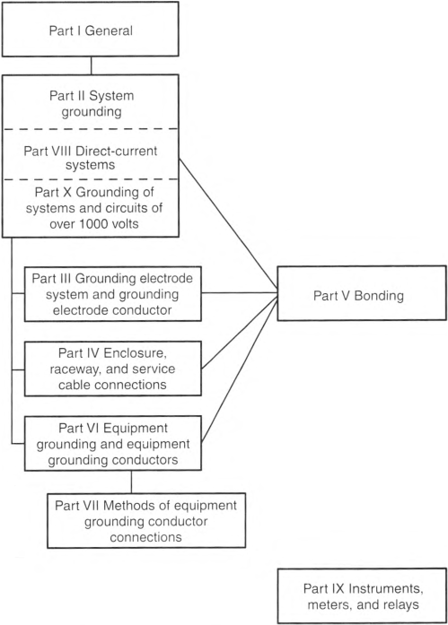
- Systems, circuits, and equipment required, permitted, or not permitted to be grounded
- Circuit conductor to be grounded on grounded systems
- Location of grounding connections
- Types and sizes of grounding and bonding conductors and electrodes
- Methods of grounding and bonding
- Conditions under which isolation, insulation, or guards are permitted to be substituted for grounding
Informational Note: See Informational Note Figure 250.1 for information on the organization of this article covering grounding and bonding requirements.
Informational Note Figure 250.1 Grounding and Bonding.
250.4 General Requirements for Grounding and Bonding.
The following general requirements identify what grounding and bonding of electrical systems are required to accomplish. The prescriptive methods contained in this article shall be followed to comply with the performance requirements of this section.
(A) Grounded Systems.
(1) Electrical System Grounding.
Electrical systems that are grounded shall be connected to earth in a manner that will limit the voltage imposed by lightning, line surges, or unintentional contact with higher-voltage lines and that will stabilize the voltage to earth during normal operation.
Informational Note No. 1: An important consideration for limiting the imposed voltage is the routing of bonding and grounding electrode conductors so that they are not any longer than necessary to complete the connection without disturbing the permanent parts of the installation and so that unnecessary bends and loops are avoided.
Informational Note No. 2: See NFPA 780-2020, Standard for the Installation of Lightning Protection Systems, for information on installation of grounding and bonding for lightning protection systems.
(2) Grounding of Electrical Equipment.
Normally noncurrent-carrying conductive materials enclosing electrical conductors or equipment, or forming part of such equipment, shall be connected to earth so as to limit the voltage to ground on these materials.
(3) Bonding of Electrical Equipment.
Normally non-current-carrying conductive materials enclosing electrical conductors or equipment, or forming part of such equipment, shall be connected together and to the electrical supply source in a manner that establishes an effective ground-fault current path.
(4) Bonding of Electrically Conductive Materials and Other Equipment.
Normally non-current-carrying electrically conductive materials that are likely to become energized shall be connected together and to the electrical supply source in a manner that establishes an effective ground-fault current path.
(5) Effective Ground-Fault Current Path.
Electrical equipment and wiring and other electrically conductive material likely to become energized shall be installed in a manner that creates a low-impedance circuit facilitating the operation of the overcurrent device or ground detector for impedance grounded systems. It shall be capable of safely carrying the maximum ground-fault current likely to be imposed on it from any point on the wiring system where a ground fault occurs to the electrical supply source. The earth shall not be considered as an effective ground-fault current path.
(B) Ungrounded Systems.
(1) Grounding Electrical Equipment.
Non-current-carrying conductive materials enclosing electrical conductors or equipment, or forming part of such equipment, shall be connected to earth in a manner that will limit the voltage imposed by lightning or unintentional contact with higher-voltage lines and limit the voltage to ground on these materials.
Informational Note: See NFPA 780-2020, Standard for the Installation of Lightning Protection Systems, for information on installation of grounding and bonding for lightning protection systems.
(2) Bonding of Electrical Equipment.
Non-current-carrying conductive materials enclosing electrical conductors or equipment, or forming part of such equipment, shall be connected together and to the supply system grounded equipment in a manner that creates a low-impedance path for ground-fault current that is capable of carrying the maximum fault current likely to be imposed on it.
(3) Bonding of Electrically Conductive Materials and Other Equipment.
Electrically conductive materials that are likely to become energized shall be connected together and to the supply system grounded equipment in a manner that creates a low-impedance path for ground-fault current that is capable of carrying the maximum fault current likely to be imposed on it.
(4) Path for Fault Current.
Electrical equipment, wiring, and other electrically conductive material likely to become energized shall be installed in a manner that creates a low-impedance circuit from any point on the wiring system to the electrical supply source to facilitate the operation of overcurrent devices should a second ground fault from a different phase occur on the wiring system. The earth shall not be considered as an effective fault-current path.
250.6 Objectionable Current.
(A) Arrangement to Prevent Objectionable Current.
The grounding and bonding of electrical systems, circuit conductors, surge arresters, surge-protective devices, and conductive normally non-current-carrying metal parts of equipment shall be installed and arranged in a manner that will prevent objectionable current.
(B) Alterations to Stop Objectionable Current.
If the use of multiple grounding or bonding connections results in objectionable current and the requirements of 250.4(A)(5) or (B)(4) are met, one or more of the following alterations shall be permitted:
- Discontinue one or more but not all of such grounding or bonding connections.
- Change the locations of the grounding or bonding connections.
- Interrupt the continuity of the conductor or conductive path causing the objectionable current.
- Take other remedial and approved action.
(C) Currents Not Classified as Objectionable Currents.
Currents resulting from abnormal conditions such as ground faults, and from currents resulting from required grounding and bonding connections shall not be classified as objectionable current for the purposes specified in 250.6(A) and (B).
(D) Limitations to Permissible Alterations.
This section shall not be considered as permitting electronic equipment to be operated on ac systems or branch circuits that are not connected to an equipment grounding conductor as required by this article. Currents that introduce electromagnetic interference or data errors in electronic equipment shall not be considered the objectionable currents addressed in this section.
(E) Isolation of Objectionable Direct-Current From Cathodic Protection Systems.
If isolation of objectionable direct currents from a cathodic protection system is required, a listed isolator device shall be permitted in the equipment grounding conductor path to provide an effective return path for ac ground-fault current while blocking the flow of direct currents.
250.8 Connection of Grounding and Bonding Equipment.
(A) Permitted Methods.
Equipment grounding conductors, grounding electrode conductors, and bonding jumpers shall be connected by one or more of the following means:
- Listed pressure connectors
- Terminal bars
- Pressure connectors listed as grounding and bonding equipment
- Exothermic welding process
- Machine screw-type fasteners that engage not less than two threads or are secured with a nut
- Thread-forming machine screws that engage not less than two threads in the enclosure
- Connections that are part of a listed assembly
- Other listed means
250.20 Alternating-Current Systems to Be Grounded.
Alternating-current systems shall be grounded in accordance with 250.20(A), (B), (C), or (D), unless prohibited elsewhere in this Code. Other systems shall be permitted to be grounded. If such systems are grounded, they shall comply with the applicable provisions of this article.
Informational Note No. 1: An example of a system permitted to be grounded is a corner-grounded delta transformer connection.
Informational Note No. 2: See 503.155, 517.61, 517.160, 668.10, and 680.23(A)(2) for examples of circuits prohibited to be grounded.
(A) Alternating-Current Systems of Less Than 50 Volts.
Alternating-current systems of less than 50 volts shall be grounded under any of the following conditions:
- If supplied by transformers, if the transformer supply system exceeds 150 volts to ground
- If supplied by transformers, if the transformer supply system is ungrounded
- If installed outside as overhead conductors
(B) Alternating-Current Systems of 50 Volts to 1000 Volts.
Alternating-current systems of 50 volts to 1000 volts that supply premises wiring and premises wiring systems shall be grounded under any of the following conditions:
- If the system can be grounded so that the maximum voltage to ground on the ungrounded conductors does not exceed 150 volts
- If the system is 3-phase, 4-wire, wye connected in which the neutral conductor is used as a circuit conductor
- If the system is 3-phase, 4-wire, delta connected in which the midpoint of one phase winding is used as a circuit conductor
Informational Note: See NFPA 70E-2021. Standard for Electrical Safety in the Workplace, Annex O, for information on impedance grounding to reduce arc-flash hazards.
250.21 Alternating-Current Systems of 50 Volts to 1000 Volts Not Required to Be Grounded.
(A) General.
The following ac systems of 50 volts to 1000 volts shall be permitted to be grounded but shall not be required to be grounded:
- Electrical systems used exclusively to supply industrial electric furnaces used for applications such as melting, refining, or tempering
- Separately derived systems used exclusively for rectifiers that supply only adjustable-speed industrial drives
- Separately derived systems supplied by transformers that have a primary voltage rating of 1000 volts or less if all the following conditions are met:
- The system is used exclusively for control circuits.
- The conditions of maintenance and supervision ensure that only qualified persons service the installation.
- Continuity of control power is required.
- Other systems that are not required to be grounded in accordance with 250.20(B)
(B) Ground Detectors.
Ground detectors shall be installed in accordance with the following:
- Ungrounded ac systems as permitted in 250.21(A)(1) through (A)(4) operating at not less than 120 volts and at 1000 volts or less shall have ground detectors installed on the system.
- The ground detection sensing equipment shall be connected as close as practicable to where the system receives its supply.
(C) Marking.
Ungrounded systems shall be legibly marked "Caution: Ungrounded System Operating - ____ Volts Between Conductors" at the source or first disconnecting means of the system. The marking shall be of sufficient durability to withstand the environment involved.
250.24 Grounding of Service-Supplied Alternating-Current Systems.
(A) System Grounding Connections.
A premises wiring system supplied by a grounded ac service shall have a grounding electrode conductor connected to the grounded service conductor, at each service, in accordance with 250.24(A)(1) through (A)(4).
(1) General.
The grounding electrode conductor connection shall be made at any accessible point from the load end of the overhead service conductors, service drop, underground service conductors, or service lateral to the terminal or bus to which the grounded service conductor is connected at the service disconnecting means.
Informational Note: See Article 100 for definitions of Service Conductors, Overhead; Service Conductors, Underground; Service Drop; and Service Lateral.
(2) Outdoor Transformer.
If the transformer supplying the service is located outside the building, at least one additional grounding connection shall be made from the grounded service conductor to a grounding electrode, either at the transformer or elsewhere outside the building.
Exception: The additional grounding electrode conductor connection shall not be made on impedance grounded systems. Impedance grounded systems shall meet the requirements of 250.36 or 250.187, as applicable.
(3) Dual-Fed Services.
For services that are dual fed (double ended) in a common enclosure or grouped together in separate enclosures and employing a secondary tie, a single grounding electrode conductor connection to the tie point of the grounded conductor(s) from each power source shall be permitted.
(4) Main Bonding Jumper as Wire or Busbar.
If the main bonding jumper specified in 250.28 is a wire or busbar and is installed from the grounded conductor terminal bar or bus to the equipment grounding terminal bar or bus in the service equipment, the grounding electrode conductor shall be permitted to be connected to the equipment grounding terminal, bar, or bus to which the main bonding jumper is connected.
(B) Load-Side Grounding Connections.
A grounded conductor shall not be connected to normally non-current-carrying metal parts of equipment, to equipment grounding conductor(s), or be reconnected to ground on the load side of the service disconnecting means except as otherwise permitted in this article.
Informational Note: See 250.30 for separately derived systems, 250.32 for connections at separate buildings or structures, and 250.142 for use of the grounded circuit conductor for grounding equipment.
(C) Main Bonding Jumper.
For a grounded system, an unspliced main bonding jumper shall be used to connect the equipment grounding conductor(s) and the service-disconnect enclosure to the grounded conductor within the enclosure for each service disconnect in accordance with 250.28.
Exception No. 1: If more than one service disconnecting means is located in an assembly listed for use as service equipment, an unspliced main bonding jumper shall bond the grounded conductor(s) to the assembly enclosure.
(D) Grounded Conductor Brought to Service Equipment.
If an ac system operating at 1000 volts or less is grounded at any point, the grounded conductor(s) shall be routed with the ungrounded conductors to each service disconnecting means and shall be connected to each disconnecting means grounded conductor(s) terminal or bus. A main bonding jumper shall connect the grounded conductor(s) to each service disconnecting means enclosure. The grounded conductor(s) shall be installed in accordance with 250.24(D)(1) through (D)(4).
Exception: If two or more service disconnecting means are located in a single assembly listed for use as service equipment, it shall be permitted to connect the grounded conductor(s) to the assembly common grounded conductor(s) terminal or bus. The assembly shall include a main bonding jumper for connecting the grounded conductor(s) to the assembly enclosure.
(2) Conductors Connected in Parallel in Two or More Raceways or Cables.
If the ungrounded service-entrance conductors are connected in parallel in two or more raceways or cables, the grounded conductors shall also be installed in each raceway or cable and shall be connected in parallel. The size of each grounded conductor(s) in each raceway or cable shall not be smaller than 1/0 AWG and shall be sized in accordance with 250.24(D)(2)(a) or (D)(2)(b) in accordance with 250.24(D)(1).
- Shall be based on the largest ungrounded conductor in each raceway or cable.
- Shall be based on the sum of the circular mil areas of the largest ungrounded conductors from each set connected in parallel in each raceway or cable.
Informational Note: See 310.10(G) for grounded conductors connected in parallel.
(3) Delta-Connected Service.
The grounded conductor of a 3-phase, 3-wire delta service shall have an ampacity not less than that of the ungrounded conductors.
(4) Impedance Grounded Service.
The impedance grounding conductor on an impedance grounded system shall be connected in accordance with 250.36 or 250.187, as applicable.
(E) Grounding Electrode Conductor.
A grounding electrode conductor shall be used to connect the equipment grounding conductors, the service-equipment enclosures, and, if the system is grounded, the grounded service conductor to the grounding electrode(s) required by Part III of this article. This conductor shall be sized in accordance with 250.66.
Impedance grounded system connections shall be made in accordance with 250.36 or 250.187, as applicable.
(F) Ungrounded System Grounding Connections.
A premises wiring system that is supplied by an ac service that is ungrounded shall have, at each service, a grounding electrode conductor connected to the grounding electrode(s) required by Part III of this article. The grounding electrode conductor shall be connected to a metal enclosure of the service conductors at any accessible point from the load end of the overhead service conductors, service drop, underground service conductors, or service lateral to the service disconnecting means.
250.25 Grounding of Systems Permitted to Be Connected on the Supply Side of the Service Disconnect.
The grounding of systems connected on the supply side of the service disconnect, in accordance with 230.82, that are in enclosures separate from the service equipment enclosure shall comply with 250.25(A) or (B).
(A) Grounded System.
If the utility supply system is grounded, the grounding of systems permitted to be connected on the supply side of the service disconnect and are installed in one or more separate enclosures from the service equipment enclosure shall comply with the requirements of 250.24(A) through (D).
(B) Ungrounded Systems.
If the utility supply system is ungrounded, the grounding of systems permitted to be connected on the supply side of the service disconnect and are installed in one or more separate enclosures from the service equipment enclosure shall comply with the requirements of 250.24(F).
250.26 Conductor to Be Grounded - Alternating-Current Systems.
If an ac premises wiring system is grounded, the conductor to be grounded shall be one of the following:
- Single-phase, 2-wire - one conductor
- Single-phase, 3-wire - the neutral conductor
- Multiphase systems having one wire common to all phases - the neutral conductor
- Multiphase systems if one phase is grounded - that phase conductor
- Multiphase systems in which one phase is used as in (2) - the neutral conductor
250.28 Main Bonding Jumper and System Bonding Jumper.
For a grounded system, main bonding jumpers and system bonding jumpers shall be installed as follows:
(A) Material.
Main bonding jumpers and system bonding jumpers shall be of copper, aluminum, copper-clad aluminum, or other corrosion-resistant material. A main bonding jumper and a system bonding jumper shall be a wire, bus, screw, or similar suitable conductor.
(B) Construction.
If a main bonding jumper or a system bonding jumper is a screw only, the screw shall be identified with a green finish that shall be visible with the screw installed.
(D) Size.
Main bonding jumpers and system bonding jumpers shall be sized in accordance with 250.28(D)(1) through (D)(3).
(1) General.
Main bonding jumpers and system bonding jumpers shall not be smaller than specified in Table 250.102(C)(1).
(2) Main Bonding Jumper for Service With More Than One Enclosure.
If a service consists of more than a single enclosure as permitted in 230.71(B), the main bonding jumper for each enclosure shall be sized in accordance with 250.28(D)(1) based on the largest ungrounded service conductor serving that enclosure.
(3) Separately Derived System With More Than One Enclosure.
If a separately derived system supplies more than a single enclosure, the system bonding jumper for each enclosure shall be sized in accordance with 250.28(D)(1) based on the largest ungrounded feeder conductor serving that enclosure, or a single system bonding jumper shall be installed at the source and sized in accordance with 250.28(D)(1) based on the equivalent size of the largest supply conductor determined by the largest sum of the areas of the corresponding conductors of each set.
250.30 Grounding Separately Derived Alternating-Current Systems.
In addition to complying with 250.30(A) for grounded systems, or as provided in 250.30(B) for ungrounded systems, separately derived systems shall comply with 250.20, 250.21, or 250.26, as applicable. Multiple power sources of the same type that are connected in parallel to form one system that supplies premises wiring shall be treated as a single separately derived system and shall be installed in accordance with 250.30.
Informational Note No. 1: An alternate ac power source, such as an on-site generator, is not a separately derived system if the grounded conductor is solidly interconnected to a service-supplied system grounded conductor. An example of such a situation is if the alternate source transfer equipment does not include a switching action in the grounded conductor and allows it to remain solidly connected to the service-supplied grounded conductor when the alternate source is operational and supplying the load served.
Informational Note No. 2: See 445.13 for the minimum size of conductors that carry fault current.
(A) Grounded Systems.
A separately derived ac system that is grounded shall comply with 250.30(A)(1) through (A)(8). Except as otherwise permitted in this article, a grounded conductor shall not be connected to normally non-current-carrying metal parts of equipment, be connected to equipment grounding conductors, or be reconnected to ground on the load side of the system bonding jumper.
Informational Note: See 250.32 for connections at separate buildings or structures and 250.142 for use of the grounded circuit conductor for grounding equipment.
Exception: Impedance grounded system grounding connections shall be made in accordance with 250.36 or 250.187, as applicable.
(1) System Bonding Jumper.
An unspliced system bonding jumper shall comply with 250.28(A) through (D). This connection shall be made at any single point on the separately derived system from the source to the first system disconnecting means or overcurrent device, or it shall be made at the source of a separately derived system that has no disconnecting means or overcurrent devices, in accordance with 250.30(A)(1)(a) or (A)(1)(b). The system bonding jumper shall remain within the enclosure where it originates. If the source is located outside the building or structure supplied, a system bonding jumper shall be installed at the grounding electrode connection in compliance with 250.30(C).
Exception No. 1: For systems installed in accordance with 450.6, a single system bonding jumper connection to the tie point of the grounded circuit conductors from each power source shall be permitted.
Exception No. 2: If a building or structure is supplied by a feeder from an outdoor separately derived system, a system bonding jumper at both the source and the first disconnecting means shall be permitted if doing so does not establish a parallel path for the grounded conductor. If a grounded conductor is used in this manner, it shall not be smaller than the size specified for the system bonding jumper but shall not be required to be larger than the ungrounded conductor(s). For the purposes of this exception, connection through the earth shall not be considered as providing a parallel path.
Exception No. 3: The size of the system bonding jumper for a system that supplies a Class 1, Class 2, or Class 3 circuit, and is derived from a transformer rated not more than 1000 volt-amperes, shall not be smaller than the derived ungrounded conductors and shall not be smaller than 14 AWG copper or 12 AWG aluminum.
- Installed at the Source. The system bonding jumper shall connect the grounded conductor to the supply-side bonding jumper and the normally non-current-carrying metal enclosure.
- Installed at the First Disconnecting Means. The system bonding jumper shall connect the grounded conductor to the supply-side bonding jumper, the disconnecting means enclosure, and the equipment grounding conductor(s).
Exception: Separately derived systems consisting of multiple sources of the same type that are connected in parallel shall be permitted to have the system bonding jumper installed at the paralleling switchgear, switchboard, or other paralleling connection point instead of at the disconnecting means located at each separate source.
(2) Supply-Side Bonding Jumper.
If the source of a separately derived system and the first disconnecting means are located in separate enclosures, a supply-side bonding jumper shall be installed with the circuit conductors from the source enclosure to the first disconnecting means enclosure. A supply-side bonding jumper shall not be required to be larger than the derived ungrounded conductors. The supply-side bonding jumper shall be permitted to be of nonflexible metal raceway type or of the wire or bus type as follows:
- A supply-side bonding jumper of the wire type shall comply with 250.102(C), based on the size of the derived ungrounded conductors.
- A supply-side bonding jumper of the bus type shall have a cross-sectional area not smaller than a supply-side bonding jumper of the wire type as determined in 250.102(C).
Exception: A supply-side bonding jumper shall not be required between enclosures for installations made in compliance with 250.30(A)(1), Exception No. 2.
(3) Grounded Conductor.
If a grounded conductor is installed and the system bonding jumper connection is not located at the source, 250.30(A)(3)(a) through (A)(3)(d) shall apply. The grounded conductor shall not be required to be larger than the derived ungrounded conductors.
- Sizing for a Single Raceway. The grounded conductor shall not be smaller than specified in Table 250.102(C)(1).
- Conductors Connected in Parallel in Two or More Raceways or Cables. If the ungrounded conductors are connected in parallel in two or more raceways or cables, the grounded conductors shall also be installed in each raceway or cable and shall be connected in parallel. The size of the grounded conductor(s) in each raceway or cable shall be based on the largest derived ungrounded conductor in each raceway or cable, or the sum of the circular mil areas of the largest derived ungrounded conductors from each set connected in parallel in each raceway or cable, in accordance with 250.30(A)(3)(a), but not smaller than 1/0 AWG.Informational Note: See 310.10(G) for grounded conductors connected in parallel.
- Delta-Connected System. The grounded conductor of a 3-phase, 3-wire delta system shall have an ampacity not less than that of the ungrounded conductors.
- Impedance Grounded System. The impedance grounding conductor of an impedance grounded system shall be installed in accordance with 250.36 or 250.187, as applicable.
(4) Grounding Electrode.
The building or structure grounding electrode system shall be used as the grounding electrode for the separately derived system. If located outdoors, the grounding electrode shall be in accordance with 250.30(C).
Exception: If a separately derived system originates in equipment that is listed and identified as suitable for use as service equipment, the grounding electrode used for the service or feeder equipment shall be permitted to be used as the grounding electrode for the separately derived system.
Informational Note No. 1: See 250.104(D) for bonding requirements for interior metal water piping in the area served by separately derived systems.
(5) Grounding Electrode Conductor, Single Separately Derived System.
A grounding electrode conductor for a single separately derived system shall be sized in accordance with 250.66 for the derived ungrounded conductors. It shall be used to connect the grounded conductor of the derived system to the grounding electrode in accordance with 250.30(A)(4), or as permitted in 250.68(C)(1) and (C)(2). This connection shall be made at the same point on the separately derived system where the system bonding jumper is connected.
Exception No. 1: If the system bonding jumper specified in 250.30(A)(1) is a wire or busbar, it shall be permitted to connect the grounding electrode conductor to the equipment grounding terminal, bar, or bus if the equipment grounding terminal, bar, or bus is of sufficient size for the separately derived system.
Exception No. 2: If the source of a separately derived system is located within equipment listed and identified as suitable for use as service equipment, the grounding electrode conductor from the service or feeder equipment to the grounding electrode shall be permitted as the grounding electrode conductor for the separately derived system, if the grounding electrode conductor is of sufficient size for the separately derived system. If the equipment grounding bus internal to the equipment is not smaller than the required grounding electrode conductor for the separately derived system, the grounding electrode connection for the separately derived system shall be permitted to be made to the bus.
Exception No. 3: A grounding electrode conductor shall not be required for a system that supplies a Class 1, Class 2, or Class 3 circuit and is derived from a transformer rated not more than 1000 volt-amperes, provided the grounded conductor is bonded to the transformer frame or enclosure by a jumper sized in accordance with 250.30(A)(1), Exception No. 3, and the transformer frame or enclosure is grounded by one of the means specified in 250.134.
(6) Grounding Electrode Conductor, Multiple Separately Derived Systems.
A common grounding electrode conductor for multiple separately derived systems shall be permitted. If installed, the common grounding electrode conductor shall be used to connect the grounded conductor of each separately derived system to the grounding electrode as specified in 250.30(A)(4). A grounding electrode conductor tap shall then be installed from each separately derived system to the common grounding electrode conductor. Each tap conductor shall connect the grounded conductor of the separately derived system to the common grounding electrode conductor. This connection shall be made at the same point on the separately derived system where the system bonding jumper is connected.
Exception No. 1: If the system bonding jumper specified in 250.30(A)(1) is a wire or busbar, it shall be permitted to connect the grounding electrode conductor tap to the equipment grounding terminal, bar, or bus, provided the equipment grounding terminal, bar, or bus is of sufficient size for the separately derived system.
Exception No. 2: A grounding electrode conductor shall not be required for a system that supplies a Class 1, Class 2, or Class 3 circuit and is derived from a transformer rated not more than 1000 volt-amperes, provided the system grounded conductor is bonded to the transformer frame or enclosure by a jumper sized in accordance with 250.30(A)(1), Exception No. 3, and the transformer frame or enclosure is grounded by one of the means specified in 250.134.
Exception No. 3: If the source of a separately derived system is located within equipment listed and identified as suitable for use as service equipment, the grounding electrode conductor from the service or feeder equipment to the grounding electrode shall be permitted as the grounding electrode conductor for the separately derived system, if the grounding electrode conductor is of sufficient size for the separately derived system. If the equipment grounding bus internal to the equipment is not smaller than the required grounding electrode conductor for the separately derived system, the grounding electrode connection for the separately derived system shall be permitted to be made to the bus.
- Common Grounding Electrode Conductor. The common grounding electrode conductor shall be permitted to be one of the following:
- A conductor of the wire type not smaller than 3/0 AWG copper or 250 kcmil aluminum
- A metal water pipe in accordance with 250.68(C)(1)
- The metal structural frame of the building or structure in accordance with 250.68(C)(2) or is connected to the grounding electrode system by a conductor not smaller than 3/0 AWG copper or 250 kcmil aluminum
- Tap Conductor Size. Each tap conductor shall be sized in accordance with 250.66 based on the derived ungrounded conductors of the separately derived system it serves.Exception to (a)(1) and (b): If the only electrodes that are present are of the types in 250.66(A), (B), or (C), the size of the common grounding electrode conductor shall not be required to be larger than the largest conductor required by 250.66(A), (B), or (C) for the type of electrode that is present.
- Connections. All tap connections to the common grounding electrode conductor shall be made at an accessible location by one of the following methods:
- A connector listed as grounding and bonding equipment.
- Listed connections to aluminum or copper busbars not smaller than 6 mm thick × 50 mm wide (1/4 in. thick × 2 in. wide) and of a length to accommodate the number of terminations necessary for the installation. If aluminum busbars are used, the installation shall also be in accordance with 250.64(A).
- The exothermic welding process.
Tap conductors shall be connected to the common grounding electrode conductor in such a manner that the common grounding electrode conductor remains without a splice or joint.
(7) Installation.
The installation of all grounding electrode conductors shall comply with 250.64(A), (B), (C), and (E).
(8) Bonding.
Structural steel and metal piping shall be connected to the grounded conductor of a separately derived system in accordance with 250.104(D).
(B) Ungrounded Systems.
The equipment of an ungrounded separately derived system shall be grounded and bonded as specified in 250.30(B)(1) through (B)(3).
(1) Grounding Electrode Conductor.
A grounding electrode conductor, sized in accordance with 250.66 for the largest derived ungrounded conductor(s) or set of derived ungrounded conductors, shall be used to connect the metal enclosures of the derived system to the grounding electrode as specified in 250.30(A)(5) or (A)(6), as applicable. This connection shall be made at any point on the separately derived system from the source to the first system disconnecting means. If the source is located outside the building or structure supplied, a grounding electrode connection shall be made in compliance with 250.30(C).
(2) Grounding Electrode.
Except as permitted by 250.34 for portable and vehicle-mounted generators, the grounding electrode shall comply with 250.30(A)(4).
(3) Bonding Path and Conductor.
A supply-side bonding jumper shall be installed from the source of a separately derived system to the first disconnecting means in compliance with 250.30(A)(2).
(C) Outdoor Source.
If the source of the separately derived system is located outside the building or structure supplied, a grounding electrode connection shall be made at the source location to one or more grounding electrodes in accordance with 250.50. In addition, the installation shall be in accordance with 250.30(A) for grounded systems or with 250.30(B) for ungrounded systems.
Exception: The grounding electrode conductor connection for impedance grounded systems shall be in accordance with 250.36 or 250.187, as applicable.
250.32 Buildings or Structures Supplied by a Feeder(s) or Branch Circuit(s).
(A) Grounding Electrode System and Grounding Electrode Conductor.
A building(s) or structure(s) supplied by a feeder(s) or branch circuit(s) shall have a grounding electrode system and grounding electrode conductor installed in accordance with Part III of Article 250.
Exception: A grounding electrode system and grounding electrode conductor shall not be required if only a single branch circuit, including a multiwire branch circuit, supplies the building or structure and the branch circuit includes an equipment grounding conductor for grounding the normally non-current-carrying metal parts of equipment.
(B) Grounded Systems.
(1) Supplied by a Feeder or Branch Circuit.
An equipment grounding conductor, as described in 250.118, shall be run with the supply conductors and be connected to the building or structure disconnecting means and to the grounding electrode(s). The equipment grounding conductor shall be used for grounding or bonding of equipment, structures, or frames required to be grounded or bonded. The equipment grounding conductor shall be sized in accordance with 250.122. Any installed grounded conductor shall not be connected to the equipment grounding conductor or to the grounding electrode(s).
Exception No. 1: For installations made in compliance with previous editions of this Code that permitted such connection, the grounded conductor run with the supply to the building or structure shall be permitted to serve as the ground-fault return path if all of the following requirements continue to be met:
(2) There are no continuous metallic paths bonded to the grounding system in each building or structure involved.
(3) Ground-fault protection of equipment has not been installed on the supply side of the feeder(s).
If the grounded conductor is used for grounding in accordance with the provision of this exception, the size of the grounded conductor shall not be smaller than the larger of either of the following:
(1) The calculated neutral load in accordance with 220.61
Exception No. 2: If system bonding jumpers are installed in accordance with 250.30(A)(1), Exception No. 2, the feeder grounded circuit conductor at the building or structure served shall be connected to the equipment grounding conductors, grounding electrode conductor, and the enclosure for the first disconnecting means.
(2) Supplied by Separately Derived System.
- With Overcurrent Protection. If overcurrent protection is provided where the conductors originate, the installation shall comply with 250.32(B)(1).
- Without Overcurrent Protection. If overcurrent protection is not provided where the conductors originate, the installation shall comply with 250.30(A). If installed, the supply-side bonding jumper shall be connected to the building or structure disconnecting means and to the grounding electrode(s).
(C) Ungrounded Systems.
(1) Supplied by a Feeder or Branch Circuit.
An equipment grounding conductor, as described in 250.118, shall be installed with the supply conductors and be connected to the building or structure disconnecting means and to the grounding electrode(s). The grounding electrode(s) shall also be connected to the building or structure disconnecting means.
(2) Supplied by a Separately Derived System.
- With Overcurrent Protection. If overcurrent protection is provided where the conductors originate, the installation shall comply with 250.32(C)(1).
- Without Overcurrent Protection. If overcurrent protection is not provided where the conductors originate, the installation shall comply with 250.30(B). If installed, the supply-side bonding jumper shall be connected to the building or structure disconnecting means and to the grounding electrode(s).
(D) Disconnecting Means Located in Separate Building or Structure on the Same Premises.
If one or more disconnecting means supply one or more additional buildings or structures under single management, and where these disconnecting means are located remote from those buildings or structures in accordance with 225.31(B), Exception No. 1 and No. 2, 700.12(D)(4), 701.12(D)(3), or 702.12, all of the following conditions shall be met:
- The connection of the grounded conductor to the grounding electrode, to normally non-current-carrying metal parts of equipment, or to the equipment grounding conductor at a separate building or structure shall not be made.
- An equipment grounding conductor for grounding and bonding any normally non-current-carrying metal parts of equipment, interior metal piping systems, and building or structural metal frames is run with the circuit conductors to a separate building or structure and connected to existing grounding electrode(s) required in Part III of this article, or, if there are no existing electrodes, the grounding electrode(s) required in Part III of this article shall be installed if a separate building or structure is supplied by more than one branch circuit.
- The connection between the equipment grounding conductor and the grounding electrode at a separate building or structure shall be made in a junction box, panelboard, or similar enclosure located immediately inside or outside the separate building or structure.
(E) Grounding Electrode Conductor.
The size of the grounding electrode conductor to the grounding electrode(s) shall not be smaller than given in 250.66, based on the largest ungrounded supply conductor. The installation shall comply with Part III of this article.
250.34 Portable, Vehicle-Mounted, and Trailer-Mounted Generators.
(A) Portable Generators.
The frame of a portable generator shall not be required to be connected to a grounding electrode as defined in 250.52 for a system supplied by the generator under both of the following conditions:
- The generator supplies only equipment mounted on the generator, cord-and-plug-connected equipment through receptacles mounted on the generator, or both.
- The normally non-current-carrying metal parts of equipment and the equipment grounding conductor terminals of the receptacles are connected to the generator frame.
(B) Vehicle-Mounted and Trailer-Mounted Generators.
The frame of a vehicle or trailer shall not be required to be connected to a grounding electrode as defined in 250.52 for a system supplied by a generator located on this vehicle or trailer under all of the following conditions:
- The frame of the generator is bonded to the vehicle or trailer frame.
- The generator supplies only equipment located on the vehicle or trailer; cord-and-plug-connected equipment through receptacles mounted on the vehicle; or both equipment located on the vehicle or trailer and cord-and-plug-connected equipment through receptacles mounted on the vehicle, trailer, or on the generator.
- The normally non-current-carrying metal parts of equipment and the equipment grounding conductor terminals of the receptacles are connected to the generator frame.
250.35 Permanently Installed Generators.
A conductor that provides an effective ground-fault current path shall be installed with the supply conductors from a permanently installed generator(s) to the first disconnecting mean(s) in accordance with 250.35(A) or (B).
(A) Separately Derived System.
If the generator is installed as a separately derived system, the requirements in 250.30 shall apply.
(B) Nonseparately Derived System.
If the generator is installed as a nonseparately derived system, and overcurrent protection is not integral with the generator assembly, a supply-side bonding jumper shall be installed between the generator equipment grounding terminal and the equipment grounding terminal, bar, or bus of the disconnecting mean(s). It shall be sized in accordance with 250.102(C) based on the size of the conductors supplied by the generator.
250.36 Impedance Grounded Systems - 480 Volts to 1000 Volts.
Impedance grounded systems in which a grounding impedance device, typically a resistor, limits the ground-fault current shall be permitted for 3-phase ac systems of 480 volts to 1000 volts if all the following conditions are met:
- The conditions of maintenance and supervision ensure that only qualified persons service the installation.
- Ground detectors are installed on the system.
- Line-to-neutral loads are not served.
Informational Note: See NFPA 70E-2021, Standard for Electrical Safety in the Workplace, Annex O, for information on impedance grounding to reduce arc-flash hazards.
(A) Location.
The grounding impedance device shall be installed between the grounding electrode conductor and the impedance grounding conductor connected to the system neutral point. If a neutral point is not available, the grounding impedance shall be installed between the grounding electrode conductor and the impedance grounding conductor connected to the neutral point derived from a grounding transformer.
(B) Impedance Grounding Conductor Insulation and Ampacity.
The impedance grounding conductor from the neutral point of the transformer or generator to its connection point to the grounding impedance shall be fully insulated.
The impedance grounding conductor shall have an ampacity of not less than the maximum current rating of the grounding impedance but in no case shall the impedance grounding conductor be smaller than 8 AWG copper or 6 AWG aluminum or copper-clad aluminum.
(C) System Grounding Connection.
The system shall not be connected to ground except through the grounding impedance device.
Informational Note: The impedance is normally selected to limit the ground-fault current to a value slightly greater than or equal to the capacitive charging current of the system. This value of impedance will also limit transient overvoltages to safe values. For guidance, refer to criteria for limiting transient overvoltages in IEEE 3003.1-2019, Recommended Practice for System Grounding of Industrial and Commercial Power Systems.
(D) Impedance Grounding Conductor Routing.
The impedance grounding conductor shall be permitted to be installed in a separate raceway from the ungrounded conductors. It shall not be required to run this conductor with the phase conductors to the first system disconnecting means or overcurrent device.
(E) Impedance Bonding Jumper.
The impedance bonding jumper (the connection between the equipment grounding conductors and the grounding impedance device) shall be an unspliced conductor run from the first system disconnecting means or overcurrent device to the grounded side of the grounding impedance device.
(F) Grounding Electrode Conductor Connection Location.
For services or separately derived systems, the grounding electrode conductor shall be connected at any point from the grounded side of the grounding impedance device to the equipment grounding connection at the service equipment or the first system disconnecting means of a separately derived system.
(G) Impedance Bonding Jumper Size.
The impedance bonding jumper shall be sized in accordance with either of the following:
- If the grounding electrode conductor connection is made at the grounding impedance device, the equipment bonding jumper shall be sized in accordance with 250.66, based on the size of the service entrance conductors for a service or the derived phase conductors for a separately derived system.
- If the grounding electrode conductor is connected at the first system disconnecting means or overcurrent device, the impedance bonding jumper shall be sized the same as the impedance grounding conductor in 250.36(B).
250.50 Grounding Electrode System.
All grounding electrodes as described in 250.52(A)(1) through (A)(7) that are present at each building or structure served shall be bonded together to form the grounding electrode system. If none of these grounding electrodes exist, one or more of the grounding electrodes specified in 250.52(A)(4) through (A)(8) shall be installed and used.
Exception: Concrete-encased electrodes of existing buildings or structures shall not be required to be part of the grounding electrode system if the rebar is not accessible for use without disturbing the concrete.
250.52 Grounding Electrodes.
(A) Electrodes Permitted for Grounding.
(1) Metal Underground Water Pipe.
A metal underground water pipe in direct contact with the earth for 3.0 m (10 ft) or more (including any metal well casing bonded to the pipe) and electrically continuous (or made electrically continuous by bonding around insulating joints or insulating pipe) to the points of connection of the grounding electrode conductor and the bonding conductor(s) or jumper(s), if installed.
(2) Metal In-Ground Support Structure(s).
One or more metal in-ground support structure(s) in direct contact with the earth vertically for 3.0 m (10 ft) or more, with or without concrete encasement. If multiple metal in-ground support structures are present at a building or a structure, it shall be permissible to bond only one into the grounding electrode system.
Informational Note: Metal in-ground support structures include, but are not limited to, pilings, casings, and other structural metal.
(3) Concrete-Encased Electrode.
A concrete-encased electrode shall consist of at least 6.0 m (20 ft) of either of the following:
- One or more bare or zinc galvanized or other electrically conductive coated rebar of not less than 13 mm (1/2 in.) in diameter, installed in one continuous 6.0 m (20 ft) length, or if in multiple pieces, the rebar shall be connected together by steel tie wires, exothermic welding, welding, or other effective means to create a 6.0 m (20 ft) or greater length
- Bare copper conductor not smaller than 4 AWG
Metal components shall be encased by at least 50 mm (2 in.) of concrete and shall be located horizontally within that portion of a concrete foundation or footing that is in direct contact with the earth or within vertical foundations or structural components or members that are in direct contact with the earth. If multiple concrete-encased electrodes are present at a building or structure, it shall be permissible to bond only one into the grounding electrode system.
Informational Note: Concrete installed with insulation, vapor barriers, films, or similar items separating the concrete from the earth is not considered to be in "direct contact" with the earth.
(5) Rod and Pipe Electrodes.
Rod and pipe electrodes shall not be less than 2.44 m (8 ft) in length and consist of the following materials.
- Grounding electrodes of pipe or conduit shall not be smaller than metric designator 21 (trade size 3/4) and, where of steel, shall have the outer surface galvanized or otherwise metal-coated for corrosion protection.
- Rod-type grounding electrodes of stainless steel and copper or zinc-coated steel shall be at least 15.87 mm (5/8 in.) in diameter, unless listed.
(7) Plate Electrodes.
Each plate electrode shall expose not less than 0.186 m2 (2 ft2) of surface to exterior soil. Electrodes of bare or electrically conductive coated iron or steel plates shall be at least 6.4 mm (1/4 in.) in thickness. Solid, uncoated electrodes of nonferrous metal shall be at least 1.5 mm (0.06 in.) in thickness.
(8) Other Local Metal Underground Systems or Structures.
Other local metal underground systems or structures such as piping systems, underground tanks, and underground metal well casings that are not bonded to a metal water pipe.
(B) Not Permitted for Use as Grounding Electrodes.
The following systems and materials shall not be used as grounding electrodes:
- Metal underground gas piping systems
- Aluminum
- The structures and structural rebar described in 680.26(B)(1) and (B)(2)
Informational Note: See 250.104(B) for bonding requirements of gas piping.
250.53 Grounding Electrode System Installation.
(A) Rod, Pipe, and Plate Electrodes.
Rod, pipe, and plate electrodes shall be free from nonconductive coatings such as paint or enamel. Rod, pipe, and plate electrodes shall meet the requirements of 250.53(A)(1) through (A)(3).
(1) Below Permanent Moisture Level.
If practicable, rod, pipe, and plate electrodes shall be embedded below permanent moisture level.
(2) Supplemental Electrode Required.
A single rod, pipe, or plate electrode shall be supplemented by an additional electrode of a type specified in 250.52(A)(2) through (A)(8). The supplemental electrode shall be permitted to be bonded to one of the following:
- Rod, pipe, or plate electrode
- Grounding electrode conductor
- Grounded service-entrance conductor
- Nonflexible grounded service raceway
- Any grounded service enclosure
Exception: If a single rod, pipe, or plate grounding electrode has a resistance to earth of 25 ohms or less, the supplemental electrode shall not be required.
(3) Supplemental Electrode.
If multiple rod, pipe, or plate electrodes are installed to meet the requirements of this section, they shall not be less than 1.8 m (6 ft) apart.
Informational Note: The paralleling efficiency of rods is increased by spacing them twice the length of the longest rod.
(4) Rod and Pipe Electrodes.
The electrode shall be installed such that at least 2.44 m (8 ft) of length is in contact with the soil. It shall be driven to a depth of not less than 2.44 m (8 ft) except that, where rock bottom is encountered, the electrode shall be driven at an oblique angle not to exceed 45 degrees from the vertical or, where rock bottom is encountered at an angle up to 45 degrees, the electrode shall be permitted to be buried in a trench that is at least 750 mm (30 in.) deep. The upper end of the electrode shall be flush with or below ground level unless the aboveground end and the grounding electrode conductor attachment are protected against physical damage as specified in 250.10.
(5) Plate Electrode.
Plate electrodes shall be installed not less than 750 mm (30 in.) below the surface of the earth.
(B) Electrode Spacing.
If more than one of the electrodes of the type specified in 250.52(A)(5) or (A)(7) are used, each electrode of one grounding system (including that used for strike termination devices) shall not be less than 1.83 m (6 ft) from any other electrode of another grounding system.
(C) Bonding Jumper.
The bonding jumper(s) used to connect the grounding electrodes together to form the grounding electrode system shall be installed in accordance with 250.64(A), (B), and (E), shall be sized in accordance with 250.66, and shall be connected in the manner specified in 250.70. Rebar shall not be used as a conductor to interconnect the electrodes of grounding electrode systems.
(D) Metal Underground Water Pipe.
If used as a grounding electrode, metal underground water pipe shall meet the requirements of 250.53(D)(1) and (D)(2).
(2) Supplemental Electrode Required.
A metal underground water pipe shall be supplemented by an additional electrode of a type specified in 250.52(A)(2) through (A)(8). If the supplemental electrode is of the rod, pipe, or plate type, it shall comply with 250.53(A). The supplemental electrode shall be bonded to one of the following:
- Grounding electrode conductor
- Grounded service-entrance conductor
- Nonflexible grounded service raceway
- Any grounded service enclosure
- As provided by 250.32(B)
Exception: The supplemental electrode shall be permitted to be bonded to the interior metal water piping as specified in 250.68(C)(1).
(E) Supplemental Grounding Electrode Bonding Jumper Size.
If the supplemental electrode is a rod, pipe, or plate electrode, that portion of the bonding jumper that is the sole connection to the supplemental grounding electrode shall not be required to be larger than 6 AWG copper wire or 4 AWG aluminum or copper-clad aluminum wire.
250.54 Auxiliary Grounding Electrodes.
One or more grounding electrodes shall be permitted to be connected to the equipment grounding conductors specified in 250.118 and shall not be required to comply with the electrode bonding requirements of 250.50 or 250.53(C) or the resistance requirements of 250.53(A)(2) Exception, but the earth shall not be used as an effective ground-fault current path as specified in 250.4(A)(5) and (B)(4).
250.58 Common Grounding Electrode.
If an ac system is connected to a grounding electrode in or at a building or structure, the same electrode shall be used to ground conductor enclosures and equipment in or on that building or structure. If separate services, feeders, or branch circuits supply a building and are required to be connected to a grounding electrode(s) the same grounding electrode(s) shall be used.
250.60 Use of Strike Termination Devices.
Conductors and driven pipes, rods, or plate electrodes used for grounding strike termination devices shall not be used in lieu of the grounding electrodes required by 250.50 for grounding wiring systems and equipment. This provision shall not prohibit the required bonding together of grounding electrodes of different systems.
Informational Note No. 1: See 250.106 for the bonding requirement of the lightning protection system components to the building or structure grounding electrode system.
Informational Note No. 2: Bonding together of all separate grounding electrodes will limit voltage differences between them and between their associated wiring systems.
250.62 Grounding Electrode Conductor Material.
The grounding electrode conductor shall be of copper, aluminum, copper-clad aluminum, or the items as permitted in 250.68(C). The material selected shall be resistant to any corrosive condition existing at the installation or shall be protected against corrosion. Conductors of the wire type shall be solid or stranded, insulated, covered, or bare.
250.64 Grounding Electrode Conductor Installation.
Grounding electrode conductors at the service, at each building or structure where supplied by a feeder(s) or branch circuit(s), or at a separately derived system shall be installed as specified in 250.64(A) through (G).
(A) Aluminum or Copper-Clad Aluminum Conductors.
Grounding electrode conductors of bare, covered, or insulated aluminum or copper-clad aluminum shall comply with the following:
- Bare or covered conductors without an extruded polymeric covering shall not be installed where subject to corrosive conditions or be installed in direct contact with concrete.
- Terminations made within outdoor enclosures that are listed and identified for the environment shall be permitted within 450 mm (18 in.) of the bottom of the enclosure.
- Aluminum or copper-clad aluminum conductors external to buildings or equipment enclosures shall not be terminated within 450 mm (18 in.) of the earth.
(B) Securing and Protection Against Physical Damage.
If exposed, a grounding electrode conductor or its enclosure shall be securely fastened to the surface on which it is carried. Grounding electrode conductors shall be permitted to be installed on or through framing members.
(1) Not Exposed to Physical Damage.
A 6 AWG or larger copper, copper-clad aluminum, or aluminum grounding electrode conductor not exposed to physical damage shall be permitted to be run along the surface of the building construction without metal covering or protection.
(2) Exposed to Physical Damage.
A 6 AWG or larger copper, copper-clad aluminum, or aluminum grounding electrode conductor exposed to physical damage shall be protected in rigid metal conduit (RMC), intermediate metal conduit (IMG), Schedule 80 rigid polyvinyl chloride conduit (PVC), reinforced thermosetting resin conduit Type XW (RTRC-XW), electrical metallic tubing (EMT), or cable armor.
(3) Smaller Than 6 AWG.
Grounding electrode conductors smaller than 6 AWG shall be protected in RMC, IMC, Schedule 80 PVC, RTRC-XW, EMT, or cable armor.
(4) In Contact With the Earth.
Grounding electrode conductors and grounding electrode bonding jumpers in contact with the earth shall not be required to comply with 300.5 or 305.15, but shall be buried or otherwise protected if subject to physical damage.
(C) Continuous.
Except as provided in 250.30(A)(5) and (A)(6), 250.30(B)(1), and 250.68(C), grounding electrode conductor(s) shall be installed in one continuous length without a splice or joint. If necessary, splices or connections shall be made as permitted in the following:
- Splicing of the wire-type grounding electrode conductor shall be permitted only by irreversible compression-type connectors listed as grounding and bonding equipment or by the exothermic welding process.
- Sections of busbars shall be permitted to be connected together to form a grounding electrode conductor.
- Bolted, riveted, or welded connections of structural metal frames of buildings or structures.
- Threaded, welded, brazed, soldered or bolted-flange connections of metal water piping.
(D) Building or Structure With Multiple Disconnecting Means in Separate Enclosures.
If a building or structure is supplied by a service or feeder with two or more disconnecting means in separate enclosures, the grounding electrode connections shall be made in accordance with 250.64(D)(1), (D)(2), or (D)(3).
(1) Common Grounding Electrode Conductor and Taps.
A common grounding electrode conductor and grounding electrode conductor taps shall be installed. The common grounding electrode conductor shall be sized in accordance with 250.66, based on the sum of the circular mil area of the largest ungrounded conductor(s) of each set of conductors that supplies the disconnecting means. If the service-entrance conductors connect directly to the overhead service conductors, service drop, underground service conductors, or service lateral, the common grounding electrode conductor shall be sized in accordance with Table 250.66, note 1.
A grounding electrode conductor tap shall extend to the inside of each disconnecting means enclosure. The grounding electrode conductor taps shall be sized in accordance with 250.66 for the largest service-entrance or feeder conductor serving the individual enclosure. The tap conductors shall be connected to the common grounding electrode conductor by one of the following methods in such a manner that the common grounding electrode conductor remains without a splice or joint:
- Exothermic welding.
- Connectors listed as grounding and bonding equipment.
- Connections to an aluminum or copper busbar not less than 6 mm thick × 50 mm wide (1/4 in. thick × 2 in. wide) and of a length to accommodate the number of terminations necessary for the installation. The busbar shall be securely fastened and shall be installed in an accessible location. Connections shall be made by a listed connector or by the exothermic welding process. If aluminum busbars are used, the installation shall comply with 250.64(A).
(2) Individual Grounding Electrode Conductors.
A grounding electrode conductor shall be connected between the grounding electrode system and one or more of the following, as applicable:
- Grounded conductor in each service equipment disconnecting means enclosure
- Equipment grounding conductor installed with the feeder(s) or branch circuit(s) for other than services
- Supply-side bonding jumper
Each grounding electrode conductor shall be sized in accordance with 250.66 based on the service-entrance or feeder conductor(s) supplying the individual disconnecting means.
(3) Common Location.
A grounding electrode conductor shall be connected in a wireway or other accessible enclosure on the supply side of the disconnecting means to one or more of the following, as applicable:
- Grounded service conductor(s)
- Equipment grounding conductor installed with the feeder
- Supply-side bonding jumper
(E) Raceways, Cable Armor, and Enclosures for Grounding Electrode Conductors.
(1) General.
Ferrous metal raceways, enclosures, and cable armor for grounding electrode conductors shall be electrically continuous from the point of attachment to cabinets or equipment to the grounding electrode and shall be securely fastened to the ground clamp or fitting. Ferrous metal raceways, enclosures, and cable armor shall be bonded at each end of the raceway or enclosure to the grounding electrode or grounding electrode conductor to create an electrically parallel path. Nonferrous metal raceways, enclosures, and cable armor shall not be required to be electrically continuous.
(3) Size.
The bonding jumper for a grounding electrode conductor(s), raceway(s), enclosure(s), or cable armor shall be the same size as, or larger than, the largest enclosed grounding electrode conductor.
(4) Wiring Methods.
If a raceway is used as protection for a grounding electrode conductor, the installation shall comply with the requirements of the applicable raceway article.
(F) Installation to Electrode(s).
Grounding electrode conductor(s) and bonding jumpers interconnecting grounding electrodes shall be installed in accordance with one of the following. The grounding electrode conductor shall be sized for the largest grounding electrode conductor required among all the electrodes connected to it.
- The grounding electrode conductor shall be permitted to be run to any convenient grounding electrode available in the grounding electrode system where the other electrode(s), if any, is connected by bonding jumpers that are installed in accordance with 250.53(C).
- Grounding electrode conductor(s) shall be permitted to be run to one or more grounding electrode(s) individually.
- Bonding jumper(s) from grounding electrode(s) shall be permitted to be connected to an aluminum or copper busbar not less than 6 mm thick × 50 mm wide (1/4 in. thick × 2 in wide.) and of sufficient length to accommodate the number of terminations necessary for the installation. The busbar shall be securely fastened and shall be installed in an accessible location. Connections shall be made by a listed connector or by the exothermic welding process. The grounding electrode conductor shall be permitted to be run to the busbar. Where aluminum busbars are used, the installation shall comply with 250.64(A).
(G) Enclosures With Ventilation Openings.
Grounding electrode conductors shall not be installed through a ventilation opening of an enclosure.
250.66 Size of Alternating-Current Grounding Electrode Conductor.
The size of the grounding electrode conductor and bonding jumper(s) for connection of grounding electrodes shall not be smaller than given in Table 250.66, except as permitted in 250.66(A) through (C).
Table 250.66 Grounding Electrode Conductor for Alternating-Current Systems.
| Size of Largest Ungrounded Conductor or Equivalent Area for Parallel Conductors (AWG/kcmil) | Size of Grounding Electrode Conductor (AWG/kcmil) | ||
|---|---|---|---|
| Copper | Aluminum or Copper-Clad Aluminum | Copper | Aluminum or Copper-Clad Aluminum |
| 2 or smaller | 1/0 or smaller | 8 | 6 |
| 1 or 1/0 | 2/0 or 3/0 | 6 | 4 |
| 2/0 or 3/0 | 4/0 or 250 | 4 | 2 |
| Over 3/0 through 350 | Over 250 through 500 | 2 | 1/0 |
| Over 350 through 600 | Over 500 through 900 | 1/0 | 3/0 |
| Over 600 through 1100 | Over 900 through 1750 | 2/0 | 4/0 |
| Over 1100 | Over 1750 | 3/0 | 250 |
Notes:
- If multiple sets of service-entrance conductors connect directly to a service drop, set of overhead service conductors, set of underground service conductors, or service lateral, the equivalent size of the largest service-entrance conductor shall be determined by the largest sum of the areas of the corresponding conductors of each set.
- If there are no service-entrance conductors, the grounding electrode conductor size shall be determined by the equivalent size of the largest service-entrance conductor required for the load to be served.
- See installation restrictions in 250.64.
(A) Connections to a Rod, Pipe, or Plate Electrode(s).
If the grounding electrode conductor or bonding jumper connected to a single or multiple rod, pipe, or plate electrode(s), or any combination thereof, as described in 250.52(A)(5) or (A)(7), does not extend on to other types of electrodes that require a larger size conductor, the grounding electrode conductor shall not be required to be larger than 6 AWG copper wire or 4 AWG aluminum or copper-clad aluminum wire.
(B) Connections to Concrete-Encased Electrodes.
If the grounding electrode conductor or bonding jumper connected to a single or multiple concrete-encased electrode(s), as described in 250.52(A)(3), does not extend on to other types of electrodes that require a larger size of conductor, the grounding electrode conductor shall not be required to be larger than 4 AWG copper wire.
(C) Connections to Ground Rings.
If the grounding electrode conductor or bonding jumper connected to a ground ring, as described in 250.52(A)(4), does not extend on to other types of electrodes that require a larger size of conductor, the grounding electrode conductor shall not be required to be larger than the conductor used for the ground ring.
250.68 Grounding Electrode Conductor and Bonding Jumper Connection to Grounding Electrodes.
The connection of a grounding electrode conductor at the service, at each building or structure where supplied by a feeder(s) or branch circuit(s), or at a separately derived system and associated bonding jumper(s) shall be made as specified 250.68(A) through (C).
(A) Accessibility.
All mechanical elements used to terminate a grounding electrode conductor or bonding jumper to a grounding electrode shall be accessible.
Exception No. 1: An encased or buried connection to a concrete-encased, driven, or buried grounding electrode shall not be required to be accessible.
Exception No. 2: Exothermic or irreversible compression connections used at terminations, together with the mechanical means used to attach such terminations to fireproofed structural metal whether or not the mechanical means is reversible, shall not be required to be accessible.
(B) Effective Grounding Path.
The connection of a grounding electrode conductor or bonding jumper to a grounding electrode shall be made in a manner that will ensure an effective grounding path. Where necessary to ensure the grounding path for a metal piping system used as a grounding electrode, bonding shall be provided around insulated joints and around any equipment likely to be disconnected for repairs or replacement. Bonding jumpers shall be of sufficient length to permit removal of such equipment while retaining the integrity of the grounding path.
(C) Grounding Electrode Conductor Connections.
Grounding electrode conductors and bonding jumpers shall be permitted to be connected at the following locations and used to extend the connection to an electrode(s):
- Interior metal water piping that is electrically continuous with a metal underground water pipe electrode and is located not more than 1.52 m (5 ft) from the point of entrance to the building, as measured along the water piping, shall be permitted to extend the connection to an electrode(s). Interior metal water piping located more than 1.52 m (5 ft) from the point of entrance to the building, as measured along the water piping, shall not be used as a conductor to interconnect electrodes of the grounding electrode system.Exception: In industrial, commercial, and institutional buildings or structures, if conditions of maintenance and supervision ensure that only qualified persons service the installation, interior metal water piping located more than 1.52 m (5 ft) from the point of entrance to the building, as measured along the water piping, shall be permitted as a bonding conductor to interconnect electrodes that are part of the grounding electrode system, or as a grounding electrode conductor, if the entire length, other than short sections passing perpendicularly through walls, floors, or ceilings, of the interior metal water pipe that is being used for the conductor is exposed.
- The metal structural frame of a building shall be permitted to be used as a conductor to interconnect electrodes that are part of the grounding electrode system, or as a grounding electrode conductor. Hold-down bolts securing the structural steel column that are connected to a concrete-encased electrode complying with 250.52(A)(3) and located in the support footing or foundation shall be permitted to connect the metal structural frame of a building or structure to the concrete-encased grounding electrode. The hold-down bolts shall be connected to the concrete-encased electrode by welding, exothermic welding, steel tie wires, or other approved means.
- A rebar-type concrete-encased electrode installed in accordance with 250.52(A)(3) with an additional rebar section extended from its location within the concrete foundation or footing to an accessible location that is not subject to corrosion shall be permitted for connection of grounding electrode conductors and bonding jumpers in accordance with the following:
- The additional rebar section shall be continuous with the grounding electrode rebar or shall be connected to the grounding electrode rebar and connected together by steel tie wires, exothermic welding, welding, or other effective means.
- The rebar extension shall not be exposed to contact with the earth without corrosion protection.
- Rebar shall not be used as a conductor to interconnect the electrodes of grounding electrode systems.
250.70 Methods of Grounding and Bonding Conductor Connection to Electrodes.
(A) General.
The grounding or bonding conductor shall be connected to the grounding electrode by exothermic welding, listed lugs, listed pressure connectors, listed clamps, or other listed means. Connections depending on solder shall not be used. Ground clamps shall be listed for the materials of the grounding electrode and the grounding electrode conductor and, if used on pipe, rod, or other buried electrodes, shall also be listed for direct soil burial or concrete encasement. Not more than one conductor shall be connected to the grounding electrode by a single clamp or fitting unless the clamp or fitting is listed for multiple conductors.
(B) Indoor Communications Systems.
For indoor communications purposes only, a listed sheet metal strap-type ground clamp having a rigid metal base that seats on the electrode and having a strap of such material and dimensions that it is not likely to stretch during or after installation shall be permitted.
Informational Note: Listed ground clamps that are identified for direct burial are also suitable for concrete encasement.
250.80 Service Raceways and Enclosures.
Metal enclosures and raceways for service conductors and equipment shall be connected to the grounded conductor if the electrical system is grounded or to the grounding electrode conductor for electrical systems that are not grounded.
Exception: Metal components that are installed in a run of underground nonmetallic raceway(s) and are isolated from possible contact by a minimum cover of 450 mm (18 in.) to all parts of the metal components shall not be required to be connected to the grounded conductor, supply-side bonding jumper, or grounding electrode conductor.
250.84 Underground Service Cable or Raceway.
(A) Underground Service Cable.
The sheath or armor of a continuous underground metal-sheathed or armored service cable system that is connected to the grounded conductor on the supply side shall not be required to be connected to the grounded conductor at the building or structure. The sheath or armor shall be permitted to be insulated from the interior metal raceway or piping.
(B) Underground Service Raceway Containing Cable.
An underground metal service raceway that contains a metal-sheathed or armored cable connected to the grounded conductor shall not be required to be connected to the grounded conductor at the building or structure. The sheath or armor shall be permitted to be insulated from the interior metal raceway or piping.
250.86 Other Conductor Enclosures and Raceways.
Except as permitted by 250.112(I), metal enclosures and raceways for other than service conductors shall be connected to the equipment grounding conductor.
Exception No. 1: Metal enclosures and raceways for conductors added to existing installations of open wire, knob-and-tube wiring, and nonmetallic-sheathed cable shall not be required to be connected to the equipment grounding conductor if these enclosures or wiring methods comply with all the following:
(2) Are in runs of less than 7.5 m (25 ft)
(3) Are free from probable contact with ground, grounded metal, metal lath, or other conductive material
(4) Are guarded against contact by persons
Exception No. 2: Short sections of metal enclosures or raceways used to provide support or protection of cable assemblies from physical damage shall not be required to be connected to the equipment grounding conductor.
Exception No. 3: Metal components shall not be required to be connected to the equipment grounding conductor or supply-side bonding jumper if either of the following conditions exist:
(1) The metal components are installed in a run of nonmetallic raceway(s) and isolated from possible contact by a minimum cover of 450 mm (18 in.) to any part of the metal components.
(2) The metal components are part of an installation of nonmetallic raceway(s) and are isolated from possible contact to any part of the metal components by being encased in not less than 50 mm (2 in.) of concrete.
250.90 General.
Bonding shall be provided if necessary to ensure electrical continuity and the capacity to conduct safely any fault current likely to be imposed.
250.92 Services.
(A) Bonding of Equipment for Services.
The normally noncurrent-carrying metal parts of equipment indicated in the following shall be bonded together:
- All raceways, cable trays, cablebus framework, auxiliary gutters, or service cable armor or sheath that enclose, contain, or support service conductors, except as permitted in 250.80
- All enclosures containing service conductors, including meter fittings, boxes, or the like, interposed in the service raceway or armor
(B) Method of Bonding at the Service.
Bonding jumpers meeting the requirements of this article shall be used around impaired connections, such as reducing washers or oversized, concentric, or eccentric knockouts. Standard locknuts or bushings shall not be the only means for the bonding required by this section but shall be permitted to be installed to make a mechanical connection of the raceway(s).
Electrical continuity at service equipment, service raceways, and service conductor enclosures shall be ensured by one or more of the following methods:
- Bonding equipment to the grounded service conductor by an applicable method in 250.8(A)
- Connections made up wrenchtight using threaded couplings, threaded entries, or listed threaded hubs on enclosures
- Threadless couplings and connectors if made up tight for metal raceways and metal-clad cables
- Other listed devices, such as bonding-type locknuts, bushings, or bushings with bonding jumpers
250.94 Bonding for Communications Systems.
Communications system bonding conductor terminations shall be connected in accordance with 250.94(A) or (B).
(A) The Intersystem Bonding Termination Device.
An intersystem bonding termination (IBT) for connecting intersystem bonding conductors shall be provided external to enclosures at the service equipment or metering equipment enclosure and at the disconnecting means for any buildings or structures that are supplied by a feeder or branch circuit. If an IBT is used, it shall comply with the following:
- Be accessible for connection and inspection
- Consist of a set of terminals with the capacity for connection of not less than three intersystem bonding conductors
- Not interfere with opening the enclosure for a service, building or structure disconnecting means, or metering equipment
- Be securely mounted as follows:
- At the service equipment, to a metal enclosure for the service equipment, to a metal meter enclosure, or to an exposed nonflexible metal service raceway, or be connected to the metal enclosure for the grounding electrode conductor with a minimum 6 AWG copper conductor
- At the disconnecting means for a building or structure that is supplied by a feeder or branch circuit, be electrically connected to the metal enclosure for the building or structure disconnecting means, or be connected to the metal enclosure for the grounding electrode conductor with a minimum 6 AWG copper conductor
- Be listed as grounding and bonding equipment
Exception: In existing buildings or structures, if any of the intersystem bonding and grounding electrode conductors required by 770.100(B)(2), 800.100(B)(2), 810.21(F)(2), and 820.100 exist, installation of an IBT shall not be required. An accessible means external to enclosures for connecting intersystem bonding and grounding electrode conductors shall be permitted at the service equipment and at the disconnecting means for any buildings or structures that are supplied by a feeder or branch circuit by at least one of the following means:
- Exposed nonflexible metal raceways
- An exposed grounding electrode conductor
- Approved means for the external connection of a copper or other corrosion-resistant bonding or grounding electrode conductor to the grounded raceway or equipment
(B) Other Means.
Connections to an aluminum or copper busbar not less than 6 mm thick × 50 mm wide (1/4 in. thick × 2 in. wide) and of a length to accommodate at least three terminations for communication systems in addition to other connections. The busbar shall be securely fastened and shall be installed in an accessible location. Connections shall be made by a listed connector. If aluminum busbars are used, the installation shall also comply with 250.64(A). The busbar shall be connected to the grounding electrode system by a conductor that is the larger of the following:
- The largest grounding electrode conductor that is connected to the busbar
- As required or permitted in 250.94(A)
Exception to (A) and (B): Means for connecting intersystem bonding conductors are not required if communications systems are not likely to be used in or on the building or structure.
Informational Note: The use of an IBT can reduce electrical noise on communication systems.
250.96 Bonding Other Enclosures.
(A) General.
Metal raceways, cable trays, cable armor, cable sheath, enclosures, frames, fittings, and other metal noncurrent-carrying parts that are to serve as equipment grounding conductors, with or without the use of wire-type supplementary equipment grounding conductors, shall be bonded if necessary to ensure electrical continuity and the capacity to conduct fault current likely to be imposed on them. Any nonconductive paint, enamel, or similar coating shall be removed at threads, contact points, and contact surfaces or shall be connected by means of fittings designed so as to make such removal unnecessary.
(B) Isolated Grounding Circuits.
If installed for the reduction of electromagnetic interference on the grounding circuit, an equipment enclosure supplied by a branch circuit shall be permitted to be isolated from a raceway containing circuits supplying only that equipment by one or more listed nonmetallic raceway fittings located at the point of attachment of the raceway to the equipment enclosure. The metal raceway shall comply with this article and shall be supplemented by an internal insulated equipment grounding conductor installed in accordance with 250.146(D) to ground the equipment enclosure.
Informational Note: Use of an isolated equipment grounding conductor does not relieve the requirement for grounding the raceway system.
250.97 Bonding for Over 250 Volts to Ground.
For circuits of over 250 volts to ground, the electrical continuity of metal raceways and cables with metal sheaths that contain any conductor other than service conductors shall be ensured by one or more of the methods specified for services in 250.92(B), except for (B)(1).
Exception: If oversized, concentric, or eccentric knockouts are not encountered, or if a box or enclosure with concentric or eccentric knockouts is listed to provide a reliable bonding connection, the following methods shall be permitted:
(1) Threadless couplings and connectors for cables with metal sheaths
(2) Two locknuts, on rigid metal conduit or intermediate metal conduit, one inside and one outside of boxes and cabinets
(3) Fittings with shoulders that seal tightly against the box or cabinet, such as electrical metallic tubing connectors, flexible metal conduit connectors, and cable connectors, with one locknut on the inside of boxes and cabinets
(4) Listed fittings
250.100 Bonding in Hazardous (Classified) Locations.
Regardless of the voltage of the electrical system, the electrical continuity of normally non-current-carrying metal parts of electrical equipment, raceways, metal-clad cable, and metal enclosures containing electrical equipment in any hazardous (classified) location, as defined in 500.5, 505.5, and 506.5, shall be ensured by any of the bonding methods specified in 250.92(B)(2) through (B)(4). One or more of these bonding methods shall be used whether or not equipment grounding conductors of the wire type are installed in the raceway or in a multiconductor cable assembly.
250.102 Grounded Conductor, Bonding Conductors, and Jumpers.
(A) Material.
Bonding jumpers shall be of copper, aluminum, copper-clad aluminum, or other corrosion-resistant material. A bonding jumper shall be a wire, bus, screw, or similar suitable conductor.
(B) Attachment.
Bonding jumpers shall be attached in the manner specified in 250.8 for circuits and equipment and in 250.70 for grounding electrodes.
(C) Size - Supply-Side Bonding Jumper.
(1) Size for Supply Conductors in a Single Raceway or Cable.
Table 250.102(C)(1) Grounded Conductor, Main Bonding Jumper, System Bonding Jumper, and Supply-Side Bonding Jumper for Alternating-Current Systems.
| Size of Largest Ungrounded Conductor or Equivalent Area for Parallel Conductors (AWG/kcmil) | Size of Grounded Conductor or Bonding Jumper (AWG/kcmil) | ||
|---|---|---|---|
| Copper | Aluminum or Copper-Clad Aluminum | Copper | Aluminum or Copper-Clad Aluminum |
| 2 or smaller | 1/0 or smaller | 8 | 6 |
| 1 or 1/0 | 2/0 or 3/0 | 6 | 4 |
| 2/0 or 3/0 | 4/0 or 250 | 4 | 2 |
| Over 3/0 through 350 | Over 250 through 500 | 2 | 1/0 |
| Over 350 through 600 | Over 500 through 900 | 1/0 | 3/0 |
| Over 600 through 1100 | Over 900 through 1750 | 2/0 | 4/0 |
| Over 1100 | Over 1750 | See Notes 1 and 2. | |
Notes:
- If the circular mil area of ungrounded supply conductors that are connected in parallel is larger than 1100 kcmil copper or 1750 kcmil aluminum, the grounded conductor or bonding jumper shall have an area not less than 121/2 percent of the area of the largest ungrounded supply conductor or equivalent area for parallel supply conductors. The grounded conductor or bonding jumper shall not be required to be larger than the largest ungrounded conductor or set of ungrounded conductors.
- If the circular mil area of ungrounded supply conductors that are connected in parallel is larger than 1100 kcmil copper or 1750 kcmil aluminum and if the ungrounded supply conductors and the bonding jumper are of different materials (copper, aluminum, or copper-clad aluminum), the minimum size of the grounded conductor or bonding jumper shall be based on the assumed use of ungrounded supply conductors of the same material as the grounded conductor or bonding jumper that has an ampacity equivalent to that of the installed ungrounded supply conductors.
- If there are no service-entrance conductors, the supply conductor size shall be determined by the equivalent size of the largest service-entrance conductor required for the load to be served.
(2) Size for Parallel Conductor Installations in Two or More Raceways or Cables.
If the ungrounded supply conductors are connected in parallel in two or more raceways or cables, the supply-side bonding jumper shall be sized in accordance with either of the following:
- An individual bonding jumper for each raceway or cable shall be selected from Table 250.102(C)(1) based on the size of the largest ungrounded supply conductor in each raceway or cable.
- A single bonding jumper installed for bonding two or more raceways or cables shall be sized in accordance with Table 250.102(C)(1) based on the sum of the circular mil areas of the largest ungrounded conductors from each set connected in parallel in each raceway or cable. The size of the grounded conductor(s) in each raceway or cable shall be based on the largest ungrounded conductor in each raceway or cable, or the sum of the circular mil areas of the largest ungrounded conductors from each set connected in parallel in each raceway or cable.
Informational Note No. 1: The term supply conductors includes ungrounded conductors that do not have overcurrent protection on their supply side and terminate at service equipment or the first disconnecting means of a separately derived system.
Informational Note No. 2: See Chapter 9, Table 8, for the circular mil area of conductors 18 AWG through 4/0 AWG.
(D) Size - Equipment Bonding Jumper on Load Side of an Overcurrent Device.
The equipment bonding jumper on the load side of an overcurrent device(s) shall be sized in accordance with 250.122.
A single common continuous equipment bonding jumper shall be permitted to connect two or more raceways or cables if the bonding jumper is sized in accordance with 250.122 for the largest overcurrent device supplying circuits therein.
(E) Installation.
Bonding jumpers or conductors and equipment bonding jumpers shall be permitted to be installed inside or outside of a raceway or an enclosure.
(2) Outside a Raceway or an Enclosure.
If installed on the outside, the length of the bonding jumper or conductor or equipment bonding jumper shall not exceed 1.8 m (6 ft) and shall be routed with the raceway or enclosure.
Exception: An equipment bonding jumper or supply-side bonding jumper longer than 1.8 m (6 ft) shall be permitted at outside pole locations for the purpose of bonding or grounding isolated sections of metal raceways or elbows installed in exposed risers of metal conduit or other metal raceway, and for bonding grounding electrodes, and shall not be required to be routed with a raceway or enclosure.
(3) Protection.
Bonding jumpers or conductors and equipment bonding jumpers shall be installed in accordance with 250.64(A) and (B).
250.104 Bonding of Piping Systems and Exposed Structural Metal.
(A) Metal Water Piping.
(1) General.
Metal water piping system(s) installed in or attached to a building or structure shall be bonded to any of the following:
- Service equipment enclosure
- Grounded conductor at the service
- Grounding electrode conductor, if of sufficient size
- One or more grounding electrodes used, if the grounding electrode conductor or bonding jumper to the grounding electrode is of sufficient size
The bonding jumper(s) shall be installed in accordance with 250.64(A), (B), and (E). The points of attachment of the bonding jumper(s) shall be accessible. The bonding jumper(s) shall be sized in accordance with Table 250.102(C)(1) except that it shall not be required to be larger than 3/0 copper or 250 kcmil aluminum or copper-clad aluminum and except as permitted in 250.104(A)(2) and (A)(3).
(2) Buildings of Multiple Occupancy.
In buildings of multiple occupancy where the metal water piping system(s) installed in or attached to a building or structure for the individual occupancies is metallically isolated from all other occupancies by use of nonmetallic water piping, the metal water piping system(s) for each occupancy shall be permitted to be bonded to the equipment grounding terminal of the switchgear, switchboard, or panelboard enclosure (other than service equipment) supplying that occupancy. The bonding jumper shall be sized in accordance with 250.102(D).
(3) Buildings or Structures Supplied by a Feeder(s) or Branch Circuit(s).
The metal water piping system(s) installed in or attached to a building or structure shall be bonded to any of the following:
- Building or structure disconnecting means enclosure where located at the building or structure
- Equipment grounding conductor run with the supply conductors
- One or more grounding electrodes used
The bonding jumper(s) shall be sized in accordance with 250.102(D). The bonding jumper shall not be required to be larger than the largest ungrounded feeder or branch-circuit conductor supplying the building or structure.
(B) Other Metal Piping.
If installed in or attached to a building or structure, a metal piping system(s), including gas piping, that is likely to become energized shall be bonded to any of the following:
- Equipment grounding conductor for the circuit that is likely to energize the piping system
- Service equipment enclosure
- Grounded conductor at the service
- Grounding electrode conductor, if of sufficient size
- One or more grounding electrodes used, if the grounding electrode conductor or bonding jumper to the grounding electrode is of sufficient size
The bonding conductor(s) or jumper(s) shall be sized in accordance with Table 250.122, and equipment grounding conductors shall be sized in accordance with Table 250.122 using the rating of the circuit that is likely to energize the piping system(s). The points of attachment of the bonding jumper(s) shall be accessible.
Informational Note No. 1: Bonding all piping and metal air ducts within the premises will provide additional safety.
Informational Note No. 2: See NFPA 54, National Fuel Gas Code, and NFPA 780, Standard for the Installation of Lightning Protection Systems, for information on gas piping systems.
(C) Structural Metal.
Exposed structural metal that is interconnected to form a metal building frame, is not intentionally grounded or bonded, and is likely to become energized shall be bonded to any of the following:
- Service equipment enclosure
- Grounded conductor at the service
- Disconnecting means for buildings or structures supplied by a feeder or branch circuit
- Grounding electrode conductor, if not smaller than a conductor sized in accordance with Table 250.102(C)(1)
- One or more grounding electrodes used, if the grounding electrode conductor or bonding jumper to the grounding electrode is not smaller than a conductor sized in accordance with Table 250.102(C)(1)
The bonding conductor(s) or jumper(s) shall be sized in accordance with Table 250.102(C)(1), except that it shall not be required to be larger than 3/0 AWG copper or 250 kcmil aluminum or copper-clad aluminum, and installed in accordance with 250.64(A), (B), and (E). The points of attachment of the bonding jumper(s) shall be accessible unless installed in compliance with 250.68(A), Exception No. 2.
(D) Separately Derived Systems.
Metal water piping systems and structural metal that is interconnected to form a building frame shall be bonded to separately derived systems in accordance with 250.104(D)(1) through (D)(3).
(1) Metal Water Piping System(s).
The grounded conductor of each separately derived system shall be bonded to the nearest accessible point of the metal water piping system(s) in the area served by each separately derived system. This connection shall be made at the same point on the separately derived system where the grounding electrode conductor is connected. Each bonding jumper shall be sized in accordance with Table 250.102(C)(1) based on the largest ungrounded conductor of the separately derived system except that it shall not be required to be larger than 3/0 AWG copper or 250 kcmil aluminum or copper-clad aluminum.
Exception No. 1: A separate bonding jumper to the metal water piping system shall not be required if the metal water piping system is used as the grounding electrode or grounding electrode conductor for the separately derived system and the connection to the water piping system is in the area served by the separately derived system.
Exception No. 2: A separate bonding jumper to the metal water piping system shall not be required if the metal in-ground support structure is used as a grounding electrode or the metal frame of a building or structure is used as the grounding electrode conductor for a separately derived system and is bonded to the metal water piping system in the area served by the separately derived system.
(2) Structural Metal.
If exposed structural metal that is interconnected to form the building frame exists in the area served by the separately derived system, it shall be bonded to the grounded conductor of each separately derived system. This connection shall be made at the same point on the separately derived system where the grounding electrode conductor is connected. Each bonding jumper shall be sized in accordance with Table 250.102(C)(1) based on the largest ungrounded conductor of the separately derived system except that it shall not be required to be larger than 3/0 AWG copper or 250 kcmil aluminum or copper-clad aluminum.
Exception No. 1: A separate bonding jumper to the building structural metal shall not be required if the metal in-ground support structure is used as a grounding electrode or the metal frame of a building or structure is used as the grounding electrode conductor for the separately derived system.
Exception No. 2: A separate bonding jumper to the building structural metal shall not be required if the water piping system of a building or structure is used as the grounding electrode or grounding electrode conductor for a separately derived system and is bonded to the building structural metal in the area served by the separately derived system.
(3) Common Grounding Electrode Conductor.
If a common grounding electrode conductor is installed for multiple separately derived systems as permitted by 250.30(A)(6), and exposed structural metal that is interconnected to form the building frame or interior metal water piping exists in the area served by the separately derived system, the metal water piping and the structural metal member shall be bonded to the common grounding electrode conductor in the area served by the separately derived system.
Exception: A separate bonding jumper from each derived system to metal water piping and to structural metal members shall not be required if the metal water piping and the structural metal members in the area served by the separately derived system are bonded to the common grounding electrode conductor.
250.106 Lightning Protection Systems.
The lightning protection system ground terminals shall be bonded to the building or structure grounding electrode system.
Informational Note No. 1: See 250.60 for use of strike termination devices.
Informational Note No. 2: See NFPA 780, Standard for the Installation of Lightning Protection Systems, which contains detailed information on grounding, bonding, and side-flash distance from lightning protection systems.
250.109 Metal Enclosures.
Metal enclosures shall be permitted to be used to connect bonding jumpers or equipment grounding conductors, or both, together to become a part of an effective ground-fault current path. If installed, metal covers, plaster rings, extension rings, and metal fittings shall be attached to these metal enclosures to ensure an effective ground-fault current path or shall be connected with bonding jumpers or equipment grounding conductors, or both.
250.110 Equipment Fastened in Place (Fixed) or Connected by Permanent Wiring Methods.
Exposed, normally non-current-carrying metal parts of fixed equipment supplied by or enclosing conductors or components that are likely to become energized shall be connected to an equipment grounding conductor under any of the following conditions:
- If within 2.5 m (8 ft) vertically or 1.5 m (5 ft) horizontally of ground or grounded metal objects and subject to contact by persons
- If located in a wet or damp location and not isolated
- If in electrical contact with metal
- If in a hazardous (classified) location
- If supplied by a wiring method that provides an equipment grounding conductor, except as permitted by 250.86, Exception No. 2, for short sections of metal enclosures
- If equipment operates with any terminal at over 150 volts to ground
Exception No. 1: If exempted by special permission, the metal frame of electrically heated appliances that have the frame permanently and effectively insulated from ground shall not be required to be grounded.
Exception No. 2: Distribution apparatus, such as transformer and capacitor cases, mounted on wooden poles at a height exceeding 2.5 m (8 ft) above ground or grade level shall not be required to be grounded.
Exception No. 3: Listed equipment protected by a system of double insulation, or its equivalent, shall not be required to be connected to the equipment grounding conductor. If such a system is employed, the equipment shall be distinctively marked.
250.112 Specific Equipment Fastened in Place (Fixed) or Connected by Permanent Wiring Methods.
Except as permitted in 250.112(F) and (I), exposed, normally non-current-carrying metal parts of equipment described in 250.112(A) through (K), and normally non-current-carrying metal parts of equipment and enclosures described in 250.112(L) and (M), shall be connected to an equipment grounding conductor, regardless of voltage.
(A) Switchgear and Switchboard Frames and Structures.
Switchgear or switchboard frames and structures supporting switching equipment, except frames of 2-wire dc switchgear or switchboards if effectively insulated from ground.
(F) Garages, Theaters, and Motion Picture Studios.
Electrical equipment in commercial garages, theaters, and motion picture studios, except pendant lampholders supplied by circuits not over 150 volts to ground.
(I) Remote-Control, Signaling, and Fire Alarm Circuits.
Equipment supplied by Class 1 circuits shall be grounded unless operating at less than 50 volts. Equipment supplied by Class 1 power-limited circuits, by Class 2 and Class 3 remote-control and signaling circuits, and by fire alarm circuits shall be grounded if system grounding is required by Part II or Part VIII of this article.
(L) Motor-Operated Water Pumps.
Motor-operated water pumps, including the submersible type.
(M) Metal Well Casings.
If a submersible pump is used in a metal well casing, the well casing shall be connected to the pump circuit equipment grounding conductor.
250.114 Equipment Connected by Cord and Plug.
Exposed, normally non-current-carrying metal parts of cord-and-plug-connected equipment shall be connected to the equipment grounding conductor under any of the following conditions:
Exception: Listed tools, listed appliances, and listed equipment covered in 250.114, list items 2 through 4, shall not be required to be connected to an equipment grounding conductor if protected by a system of double insulation or its equivalent. Double-insulated equipment shall be distinctively marked.
- In hazardous (classified) locations
- If operated at over 150 volts to groundException No. 1 to (2): Motors, if guarded, shall not be required to be connected to an equipment grounding conductor.Exception No. 2 to (2): Metal frames of electrically healed appliances, exempted by special permission, shall not be required to be connected to an equipment grounding conductor, in which case the frames shall be permanently and effectively insulated from ground.
- In residential occupancies:
- Refrigerators, freezers, icemakers, and air conditioners
- Clothes-washing, clothes-drying, and dish-washing machines; ranges; kitchen waste disposers; information technology equipment; sump pumps; and electrical aquarium equipment
- Hand-held motor-operated tools, stationary and fixed motor-operated tools, and light industrial motor-operated tools
- Motor-operated appliances of the following types: hedge clippers, lawn mowers, snow blowers, and wet scrubbers
- Portable handlamps
- In other than residential occupancies:
- Refrigerators, freezers, icemakers, and air conditioners
- Clothes-washing, clothes-drying, and dish-washing machines; information technology equipment; sump pumps; and electrical aquarium equipment
- Hand-held motor-operated tools, stationary and fixed motor-operated tools, and light industrial motor-operated tools
- Motor-operated appliances of the following types: hedge clippers, lawn mowers, snow blowers, and wet scrubbers
- Portable handlamps
- Cord-and-plug-connected appliances used in damp or wet locations or by persons standing on the ground, standing on metal floors, or working inside of metal tanks or boilers
- Tools likely to be used in wet or conductive locations
Exception: Tools and portable handlamps and portable luminaires likely to be used in wet or conductive locations shall not be required to be connected to an equipment grounding conductor if supplied through an isolating transformer with an ungrounded secondary of not over 50 volts.
250.116 Nonelectrical Equipment.
The metal parts of the following nonelectrical equipment described in this section shall be connected to the equipment grounding conductor:
- Frames and tracks of electrically operated cranes and hoists
- Frames of nonelectrically driven elevator cars to which electrical conductors are attached
- Hand-operated metal shifting ropes or cables of electric elevators
Informational Note: If extensive metal in or on buildings or structures may become energized and is subject to personal contact, adequate bonding and grounding will provide additional safety.
250.118 Types of Equipment Grounding Conductors.
(A) Permitted.
Each equipment grounding conductor run with or enclosing the circuit conductors shall be one or more or a combination of the following:
- A copper, aluminum, or copper-clad aluminum conductor. This conductor shall be solid or stranded; insulated, covered, or bare; and in the form of a wire or a busbar of any shape.
- Rigid metal conduit.
- Intermediate metal conduit.
- Electrical metallic tubing.
- Listed flexible metal conduit meeting all the following conditions:
- The conduit is terminated in listed fittings.
- The circuit conductors contained in the conduit are protected by overcurrent devices rated at 20 amperes or less.
- The size of the conduit does not exceed metric designator 35 (trade size 11/4).
- The combined length of flexible metal conduit, flexible metallic tubing, and liquidtight flexible metal conduit in the same effective ground-fault current path does not exceed 1.8 m (6 ft).
- If flexibility is necessary to minimize the transmission of vibration from equipment or to provide flexibility for equipment that requires movement after installation, a wire-type equipment grounding conductor or a bonding jumper in accordance with 250.102(E)(2) shall be installed.
- If flexible metal conduit is constructed of stainless steel, a wire-type equipment grounding conductor or bonding jumper in accordance with 250.102(E)(2) shall be installed.
- Listed liquidtight flexible metal conduit meeting all the following conditions:
- The conduit is terminated in listed fittings.
- For metric designators 12 through 16 (trade sizes 3/8 through 1/2), the circuit conductors contained in the conduit are protected by overcurrent devices rated at 20 amperes or less.
- For metric designators 21 through 35 (trade sizes 3/4 through 11/4), the circuit conductors contained in the conduit are protected by overcurrent devices rated not more than 60 amperes and there is no flexible metal conduit, flexible metallic tubing, or liquidtight flexible metal conduit in metric designators 12 through 16 (trade sizes 3/8 through 1/2) in the effective ground-fault current path.
- The combined length of flexible metal conduit, flexible metallic tubing, and liquidtight flexible metal conduit in the same effective ground-fault current path does not exceed 1.8 m (6 ft).
- If flexibility is necessary to minimize the transmission of vibration from equipment or to provide flexibility for equipment that requires movement after installation, a wire-type equipment grounding conductor or a bonding jumper in accordance with 250.102(E)(2) shall be installed.
- If liquidtight flexible metal conduit contains a stainless steel core, a wire-type equipment grounding conductor or a bonding jumper in accordance with 250.102(E)(2) shall be installed.
- Flexible metallic tubing if the tubing is terminated in listed fittings and meeting the following conditions:
- The circuit conductors contained in the tubing are protected by overcurrent devices rated at 20 amperes or less.
- The combined length of flexible metal conduit, flexible metallic tubing, and liquidtight flexible metal conduit in the same effective ground-fault current path does not exceed 1.8 m (6 ft).
- Armor of Type AC cable as provided in 320.108.
- The copper sheath of mineral-insulated, metal-sheathed cable Type MI.
- Type MC cable that provides an effective ground-fault current path in accordance with one or more of the following:
- It contains an insulated or uninsulated equipment grounding conductor in compliance with 250.118(1).
- The combined metallic sheath and uninsulated equipment grounding/bonding conductor of interlocked metal tape-type MC cable that is listed and identified as an equipment grounding conductor
- The metallic sheath or the combined metallic sheath and equipment grounding conductors of the smooth or corrugated tube-type MC cable that is listed and identified as an equipment grounding conductor
- Cable trays as permitted in 392.10 and 392.60.
- Cablebus framework as permitted in 370.60(1).
- Other listed electrically continuous metal raceways and listed auxiliary gutters.
- Surface metal raceways listed for grounding.
Informational Note: See Article 100 for a definition of effective ground-fault current path.
(B) Not Permitted.
The following shall not be used as equipment grounding conductors.
- Exception: A wire-type equipment grounding conductor installed in compliance with 250.6(A) and the applicable requirements for both the equipment grounding conductor and the grounding electrode conductor in Parts II. III, and VI of this article shall be permitted to serve as both an equipment grounding conductor and a grounding electrode conductor.
- Structural metal frame of a building or structure
250.119 Identification of Wire-Type Equipment Grounding Conductors.
(A) General.
Unless required elsewhere in this Code, equipment grounding conductors shall be permitted to be bare, covered, or insulated. Individually covered or insulated equipment grounding conductors of the wire type shall have a continuous outer finish that is either green or green with one or more yellow stripes except as permitted in this section. Conductors with insulation or individual covering that is green, green with one or more yellow stripes, or otherwise identified as permitted by this section shall not be used for ungrounded or grounded circuit conductors.
Exception No. 1: Power-limited Class 2 or Class 3 cables, power-limited fire alarm cables, or communications cables containing only circuits operating at less than 50 volts ac or 60 volts dc if connected to equipment not required to be grounded shall be permitted to use a conductor with green insulation or green with one or more yellow stripes for other than equipment grounding purposes.
Exception No. 2: Flexible cords having an integral insulation and jacket without an equipment grounding conductor shall be permitted to have a continuous outer finish that is green.
Informational Note: An example of a flexible cord with integral-type insulation is Type SPT-2, 2 conductor.
Exception No. 3: Conductors with green insulation shall be permitted to be used as ungrounded signal conductors where installed between the output terminations of traffic signal control and traffic signal indicating heads. Signaling circuits installed in accordance with this exception shall include an equipment grounding conductor in accordance with 250.118. Wire-type equipment grounding conductors shall be bare or have insulation or covering that is green with one or more yellow stripes.
(B) Conductors 4 AWG and Larger.
Equipment grounding conductors 4 AWG and larger shall comply with the following:
- At the time of installation, if the insulation does not comply with 250.119(A), it shall be permanently identified as an equipment grounding conductor at each end and at every point where the conductor is accessible.Exception: Conductors 4 AWG and larger shall not be required to be marked in conduit bodies that contain no splices or unused hubs.
- Identification shall encircle the conductor and shall be accomplished by one of the following:
- Stripping the insulation or covering from the entire exposed length
- Coloring the insulation or covering green at the termination
- Marking the insulation or covering with green tape or green adhesive labels at the termination
(C) Multiconductor Cable.
One or more insulated conductors in a multiconductor cable, at the time of installation, shall be permitted to be permanently identified as equipment grounding conductors at each end and at every point where the conductors are accessible by one of the following means:
(D) Flexible Cord.
Equipment grounding conductors in flexible cords shall be insulated and shall have a continuous outer finish that is either green or green with one or more yellow stripes.
250.120 Equipment Grounding Conductor Installation.
(A) Raceway, Cable Trays, Cable Armor, Cablebus, or Cable Sheaths.
If it consists of a raceway, cable tray, cable armor, cablebus framework, or cable sheath or if it is a wire within a raceway or cable, it shall be installed in accordance with the applicable provisions in this Code using fittings for joints and terminations approved for use with the type of raceway or cable used. All connections, joints, and fittings shall be made tight using suitable tools.
Informational Note: See the UL Guide Information for Electrical Circuit Integrity Systems (FHIT) for equipment grounding conductors installed in a raceway that are part of a listed electrical circuit protective system or a listed fire-resistive cable system.
(B) Aluminum and Copper-Clad Aluminum Conductors.
Equipment grounding conductors of bare, covered, or insulated aluminum or copper-clad aluminum shall comply with the following:
- Unless part of an applicable cable wiring method, bare or covered conductors shall not be installed if subject to corrosive conditions or be installed in direct contact with concrete, masonry, or the earth.
- Terminations made within outdoor enclosures that are listed and identified for the environment shall be permitted within 450 mm (18 in.) of the bottom of the enclosure.
- Aluminum or copper-clad aluminum conductors external to buildings or enclosures shall not be terminated within 450 mm (18 in.) of the earth, unless terminated within a listed wire connector system.
(C) Equipment Grounding Conductors Smaller Than 6 AWG.
If not routed with circuit conductors as permitted in 250.130(C) and 250.134, Exception No. 2, equipment grounding conductors smaller than 6 AWG shall be protected from physical damage by an identified raceway or cable armor unless installed within hollow spaces of the framing members of buildings or structures and if not subject to physical damage.
250.122 Size of Equipment Grounding Conductors.
Table 250.122 Minimum Size Equipment Grounding Conductors for Grounding Raceway and Equipment.
| Rating or Setting of Automatic Overcurrent Device in Circuit Ahead of Equipment, Conduit, etc., Not Exceeding (Amperes) | Size (AWG or kcmil) | |
|---|---|---|
| Copper | Aluminum or Copper-Clad Aluminum* | |
| 15 | 14 | 12 |
| 20 | 12 | 10 |
| 60 | 10 | 8 |
| 100 | 8 | 6 |
| 200 | 6 | 4 |
| 300 | 4 | 2 |
| 400 | 3 | 1 |
| 500 | 2 | 1/0 |
| 600 | 1 | 2/0 |
| 800 | 1/0 | 3/0 |
| 1000 | 2/0 | 4/0 |
| 1200 | 3/0 | 250 |
| 1600 | 4/0 | 350 |
| 2000 | 250 | 400 |
| 2500 | 350 | 600 |
| 3000 | 400 | 600 |
| 4000 | 500 | 750 |
| 5000 | 700 | 1250 |
| 6000 | 800 | 1250 |
Note: Where necessary to comply with 250.4(A)(5) or (B)(4), the equipment grounding conductor shall be sized larger than given in this table.
*See installation restrictions in 250.120.
(A) General.
Copper, aluminum, or copper-clad aluminum equipment grounding conductors of the wire type shall not be smaller than shown in Table 250.122. The equipment grounding conductor shall not be required to be larger than the circuit conductors supplying the equipment. If a cable tray, a raceway, or a cable armor or sheath is used as the equipment grounding conductor, as provided in 250.118 and 250.134(1), it shall comply with 250.4(A)(5) or (B)(4).
(B) Increased in Size.
If ungrounded conductors are increased in size for any reason other than as required in 310.15(B) or 310.15(C), wire-type equipment grounding conductors, if installed, shall be increased in size proportionately to the increase in circular mil area of the ungrounded conductors.
Exception: Equipment grounding conductors shall be permitted to be sized by a qualified person to provide an effective ground fault current path in accordance with 250.4(A)(5) or (B)(4)
(C) Multiple Circuits.
A single equipment grounding conductor shall be permitted to be installed for multiple circuits that are installed in the same raceway, cable, trench, or cable tray. It shall be sized from Table 250.122 for the largest overcurrent device protecting circuit conductors in the raceway, cable, trench, or cable tray. Equipment grounding conductors installed in cable trays shall meet the minimum requirements of 392.10(B)(1)(c).
(D) Motor Circuits.
Equipment grounding conductors for motor circuits shall be sized in accordance with 250.122(D)(1) or (D)(2).
(1) General.
The equipment grounding conductor size shall not be smaller than determined by 250.122(A) based on the rating of the branch-circuit short-circuit and ground-fault protective device.
(2) Instantaneous-Trip Circuit Breaker and Motor Short-Circuit Protector.
If the overcurrent device is an instantaneous-trip circuit breaker or a motor short-circuit protector, the equipment grounding conductor shall be sized not smaller than that given by 250.122(A) using the maximum permitted rating of a dual element time-delay fuse selected for branch-circuit short-circuit and ground-fault protection in accordance with 430.52(C)(1)(a).
(E) Flexible Cord and Fixture Wire.
The equipment grounding conductor in a flexible cord with the largest circuit conductor 10 AWG or smaller, and the equipment grounding conductor used with fixture wires of any size in accordance with 240.5, shall not be smaller than 18 AWG copper and shall not be smaller than the circuit conductors. The equipment grounding conductor in a flexible cord with a circuit conductor larger than 10 AWG shall be sized in accordance with Table 250.122.
(F) Conductors in Parallel.
For circuits of parallel conductors as permitted in 310.10(G), the equipment grounding conductor shall be installed in accordance with 250.122(F)(1) or (F)(2).
(1) Conductor Installations in Raceways, Auxiliary Gutters, or Cable Trays.
- Single Raceway or Cable Tray, Auxiliary Gutter, or Cable Tray. If circuit conductors are connected in parallel in the same raceway, auxiliary gutter, or cable tray, a single wire-type conductor shall be permitted as the equipment grounding conductor. The wire-type equipment grounding conductor shall be sized in accordance with 250.122 based on the overcurrent protective device for the feeder or branch circuit.
- Multiple Raceways. If conductors are installed in multiple raceways and are connected in parallel, a wire-type equipment grounding conductor, if used, shall be installed in each raceway and shall be connected in parallel. The equipment grounding conductor installed in each raceway shall be sized in accordance with 250.122 based on the rating of the overcurrent protective device for the feeder or branch circuit.
- Wire-Type Equipment Grounding Conductors in Cable Trays. Wire-type equipment grounding conductors installed in cable trays shall meet the minimum requirements of 392.10(B)(1)(c).
- Metal Raceways, Auxiliary Gutters, or Cable Trays. Metal raceways or auxiliary gutters in accordance with 250.118 or cable trays complying with 392.60(B) shall be permitted as the equipment grounding conductor.
(2) Multiconductor Cables.
- Except as provided in 250.122(F)(2)(c) for raceway or cable tray installations, the equipment grounding conductor in each multiconductor cable shall be sized in accordance with 250.122 based on the overcurrent protective device for the feeder or branch circuit.
- If circuit conductors of multiconductor cables are connected in parallel, the equipment grounding conductor(s) in each cable shall be connected in parallel.
- If multiconductor cables are paralleled in the same raceway, auxiliary gutter, or cable tray, a single equipment grounding conductor that is sized in accordance with 250.122 shall be permitted in combination with the equipment grounding conductors provided within the multiconductor cables and shall all be connected together.
- Equipment grounding conductors installed in cable trays shall meet the minimum requirements of 392.10(B)(1)(c). Cable trays complying with 392.60(B), metal raceways in accordance with 250.118, or auxiliary gutters shall be permitted as the equipment grounding conductor.
(G) Feeder Taps.
Equipment grounding conductors installed with feeder taps shall not be smaller than shown in Table 250.122 based on the rating of the overcurrent device ahead of the feeder on the supply side ahead of the tap but shall not be required to be larger than the tap conductors.
250.124 Equipment Grounding Conductor Continuity.
(A) Separable Connections.
Separable connections such as those provided in drawout equipment or attachment plugs and mating connectors and receptacles shall provide for first-make, last-break of the equipment grounding conductor. First-make, last-break shall not be required if interlocked equipment, plugs, receptacles, and connectors preclude energization without grounding continuity.
(B) Switches.
No automatic cutout or switch shall be placed in the equipment grounding conductor of a premises wiring system unless the opening of the cutout or switch disconnects all sources of energy.
250.126 Identification of Wiring Device Terminals.
The terminal for the connection of the equipment grounding conductor shall be identified by one of the following: 
- A green, not readily removable terminal screw with a hexagonal head.
- A green, hexagonal, not readily removable terminal nut.
- A green pressure wire connector. If the terminal for the equipment grounding conductor is not visible, the conductor entrance hole shall be marked with the word green or ground, the letters G or GR, a grounding symbol, or otherwise identified by a distinctive green color. If the terminal for the equipment grounding conductor is readily removable, the area adjacent to the terminal shall be similarly marked.
Informational Note: See Informational Note Figure 250.126.
Informational Note Figure 250.126 One Example of a Symbol Used to Identify the Grounding Termination Point for an Equipment Grounding Conductor.
250.130 Equipment Grounding Conductor Connections.
Equipment grounding conductor connections at the source of separately derived systems shall be made in accordance with 250.30(A)(1). Equipment grounding conductor connections at service equipment shall be made as indicated in 250.130(A) or (B). For replacement of non-grounding-type receptacles with grounding-type receptacles, or snap switches without an equipment grounding terminal with snap switches with an equipment grounding terminal, and for branch-circuit extensions only in existing installations that do not have an equipment grounding conductor in the branch circuit, connections shall be permitted as indicated in 250.130(C).
(A) For Grounded Systems.
The connection shall be made by bonding the equipment grounding conductor to the grounded service conductor and the grounding electrode conductor.
(B) For Ungrounded Systems.
The connection shall be made by bonding the equipment grounding conductor to the grounding electrode conductor.
(C) Replacement of Nongrounding Receptacle or Snap Switch and Branch Circuit Extensions.
The equipment grounding conductor that is connected to a grounding-type receptacle, a snap switch with an equipment grounding terminal, or a branch-circuit extension shall be permitted to be connected to any of the following:
- Any accessible point on the grounding electrode system as described in 250.50
- Any accessible point on the grounding electrode conductor
- The equipment grounding terminal bar within the enclosure where the branch circuit for the receptacle or branch circuit originates
- An equipment grounding conductor that is part of another branch circuit that originates from the enclosure where the branch circuit for the receptacle, snap switch, or branch circuit originates
- For grounded systems, the grounded service conductor within the service equipment enclosure
- For ungrounded systems, the grounding terminal bar within the service equipment enclosure
Informational Note No. 1: See 406.4(D) for the use of a ground-fault circuit-interrupting type of receptacle.
Informational Note No. 2: See 404.9(B) for requirements regarding grounding of snap switches.
250.132 Short Sections of Raceway or Cable Armor.
Isolated sections of metal raceway or cable armor, if required to be connected to an equipment grounding conductor, shall be connected in accordance with 250.134.
250.134 Equipment Fastened in Place or Connected by Permanent Wiring Methods (Fixed).
Unless connected to the grounded circuit conductor as permitted by 250.32, 250.140, and 250.142, non-current-carrying metal parts of equipment, raceways, and other enclosures, if grounded, shall be connected to an equipment grounding conductor by one of the following methods:
- By connecting to any of the equipment grounding conductors permitted by 250.118(2) through (14)
- By connecting to an equipment grounding conductor of the wire type that is contained within the same raceway, contained within the same cable, or otherwise run with the circuit conductors
Exception No. 1: As provided in 250.130(C), the equipment grounding conductor shall be permitted to be run separately from the circuit conductors.
Exception No. 2: For dc circuits, the equipment grounding conductor shall be permitted to be run separately from the circuit conductors
250.136 Equipment Secured to a Metal Rack or Structure.
If a metal rack or structure is connected to an equipment grounding conductor in accordance with 250.134, it shall be permitted to serve as the equipment grounding conductor for electrical equipment secured to and in electrical contact with the metal rack or structure.
250.138 Cord-and-Plug-Connected Equipment.
Non-current-carrying metal parts of cord-and-plug-connected equipment, if required to be connected to an equipment grounding conductor, shall be connected by one of the methods in 250.138(A) or (B).
(A) By Means of an Equipment Grounding Conductor.
By means of an equipment grounding conductor run with the power supply conductors in a cable assembly or flexible cord properly terminated in a grounding-type attachment plug with one fixed grounding contact.
Exception: The grounding contacting pole of grounding-type plug-in ground-fault circuit interrupters shall be permitted to be of the movable, self-restoring type, on circuits operating at not over 150 volts between any two conductors or over 150 volts between any conductor and ground.
(B) By Means of a Separate Flexible Wire or Strap.
By means of a separate flexible wire or strap, insulated or bare, connected to an equipment grounding conductor, and protected as well as practicable against physical damage, if part of equipment.
250.140 Frames of Ranges and Clothes Dryers.
Frames of electric ranges, wall-mounted ovens, counter-mounted cooking units, clothes dryers, and outlet or junction boxes that are part of the circuit shall be connected to the equipment grounding conductor in accordance with 250.140(A) or the grounded conductor in accordance with 250.140(B).
(A) Equipment Grounding Conductor Connections.
The circuit supplying the appliance shall include an equipment grounding conductor. The frame of the appliance shall be connected to the equipment grounding conductor in the manner specified by 250.134 or 250.138.
(B) Grounded Conductor Connections.
For existing branch-circuit installations only, if an equipment grounding conductor is not present in the outlet or junction box the frame of the appliance shall be permitted to be connected to the grounded conductor if all the conditions in the following list items (1), (2), and (3) are met and the grounded conductor complies with either list item (4) or (5):
- The supply circuit is 120/240-volt, single-phase, 3-wire; or 208Y/120-volt derived from a 3-phase, 4-wire, wye connected system.
- The grounded conductor is not smaller than 10 AWG copper or 8 AWG aluminum or copper-clad aluminum.
- Grounding contacts of receptacles furnished as part of the equipment are bonded to the equipment.
- The grounded conductor is insulated, or the grounded conductor is uninsulated and part of a Type SE service-entrance cable and the branch circuit originates at the service equipment.
- The grounded conductor is part of a Type SE service-entrance cable that originates in equipment other than a service. The grounded conductor shall be insulated or field covered within the supply enclosure with listed insulating material, such as tape or sleeving to prevent contact of the uninsulated conductor with any normally noncurrent-carrying metal parts.
250.142 Use of Grounded Circuit Conductor for Grounding Equipment.
(A) Supply-Side Equipment.
A grounded circuit conductor shall be permitted to be connected to non-current-carrying metal parts of equipment, raceways, and other enclosures at any of the following locations:
- On the supply side or within the enclosure of the ac service disconnecting means
- On the supply side or within the enclosure of the main disconnecting means for separate buildings as provided in 250.32(B)(1) Exception No. 1
- On the supply side or within the enclosure of the main disconnecting means or overcurrent devices of a separately derived system where permitted by 250.30(A)(1)
(B) Load-Side Equipment.
Except as permitted in 250.30(A)(1), 250.32(B)(1), Exception No. 1, and Part X of Article 250, a grounded circuit conductor shall not be connected to noncurrent-carrying metal parts of equipment on the load side of the service disconnecting means or on the load side of a separately derived system disconnecting means or the overcurrent devices for a separately derived system not having a main disconnecting means.
Exception No. 1: The frames of ranges, wall-mounted ovens, counter-mounted cooking units, and clothes dryers under the conditions permitted for existing installations by 250.140 shall be permitted to be connected to the grounded circuit conductor.
Exception No. 2: It shall be permissible to connect meter enclosures to the grounded circuit conductor on the load side of the service disconnect if all of the following conditions apply:
(1) Ground-fault protection of equipment is not installed.
(3) The size of the grounded circuit conductor is not smaller than the size specified in Table 250.122 for equipment grounding conductors.
250.144 Multiple Circuit Connections.
If equipment is required to be grounded and is supplied by more than one circuit containing an equipment grounding conductor, a means to terminate each equipment grounding conductor meeting the requirements of 250.8 shall be provided as specified in 250.134 and 250.138.
250.146 Connecting Receptacle Grounding Terminal to an Equipment Grounding Conductor.
An equipment bonding jumper shall be used to connect the grounding terminal of a grounding-type receptacle to a metal box that is connected to an equipment grounding conductor, except as permitted in 250.146(A) through (D). The equipment bonding jumper shall be sized in accordance with Table 250.122.
(A) Surface-Mounted Box.
If a metal box is mounted on the surface, the direct metal-to-metal contact between the device yoke or strap to the box shall be permitted to provide the required effective ground-fault current path. At least one of the insulating washers shall be removed from receptacles that do not have a contact yoke or device to ensure direct metal-to-metal contact. Direct metal-to-metal contact for providing continuity applies to cover-mounted receptacles if the box and cover combination are listed as providing continuity between the box and the receptacle. A listed exposed work cover shall be permitted to be the grounding and bonding means under both of the following conditions:
- The device is attached to the cover with at least two fasteners that are permanent (such as a rivet) or have a thread-locking or screw- or nut-locking means.
- The cover mounting holes are located on a flat nonraised portion of the cover.
(C) Floor Boxes.
Floor boxes designed for and listed as providing continuity between the box and the device shall be permitted.
(D) Isolated Ground Receptacles.
If installed for the reduction of electromagnetic interference on the equipment grounding conductor, a receptacle in which the grounding terminal is purposely insulated from the receptacle mounting means shall be permitted. The receptacle grounding terminal shall be connected to an insulated equipment grounding conductor run with the circuit conductors. This equipment grounding conductor shall be permitted to pass through one or more panelboards without a connection to the panelboard grounding terminal bar as permitted in 408.40, Exception, so as to terminate within the same building or structure directly at an equipment grounding conductor terminal of the applicable derived system or service. If installed in accordance with this section, this equipment grounding conductor shall also be permitted to pass through boxes, wireways, or other enclosures without being connected to such enclosures.
Informational Note: Use of an isolated equipment grounding conductor does not relieve the requirement for connecting the raceway system and outlet box to an equipment grounding conductor.
250.148 Continuity of Equipment Grounding Conductors and Attachment in Boxes.
If circuit conductors are spliced within a box or terminated on equipment within or supported by a box, the installation shall comply with 250.148(A) through (D).
Exception: The equipment grounding conductor permitted in 250.146(D) shall not be required to be connected to the other equipment grounding conductors or to the box.
(B) Equipment Grounding Conductor Continuity.
The arrangement of grounding connections shall be such that the disconnection or the removal of a luminaire, receptacle, or other device fed from the box does not interrupt the electrical continuity of the equipment grounding conductor(s) providing an effective ground-fault current path.
(C) Metal Boxes.
A connection used for no other purpose shall be made between the metal box and the equipment grounding conductor(s). The equipment bonding jumper or equipment grounding conductor shall be sized from Table 250.122 based on the largest overcurrent device protecting circuit conductors in the box.
250.160 General.
Direct-current systems shall comply with Part VIII and other sections of Article 250 not specifically intended for ac systems.
250.162 Direct-Current Circuits and Systems to Be Grounded.
(A) Two-Wire, Direct-Current Systems.
A 2-wire, dc system supplying premises wiring and operating at greater than 60 volts but not greater than 300 volts shall be grounded.
Exception No. 1: A system equipped with a ground detector and supplying only industrial equipment in limited areas shall not be required to be grounded if installed immediately adjacent to, or integral with, the source of supply.
Exception No. 2: A rectifier-derived dc system supplied from an ac system complying with 250.20 shall not be required to be grounded.
Exception No. 3: Direct-current fire alarm circuits having a maximum current of 0.030 ampere as specified in Article 760, Part III, shall not be required to be grounded.
250.164 Point of Connection for Direct-Current Systems.
(A) Off-Premises Source.
Direct-current systems to be grounded and supplied from an off-premises source shall have the grounding connection made at one or more supply stations. A grounding connection shall not be made at individual services or at any point on the premises wiring.
(B) On-Premises Source.
If the dc system source is located on the premises, a grounding connection shall be made at one of the following:
- The source
- The first system disconnection means or overcurrent device
- By other means that accomplish system protection and that use equipment listed and identified for the use
250.166 Size of the Direct-Current Grounding Electrode Conductor.
The size of the grounding electrode conductor for a dc system shall be as specified in 250.166(A) and (B), except as permitted by 250.166(C) through (E). The grounding electrode conductor for a dc system shall meet the sizing requirements in this section but shall not be required to be larger than 3/0 copper or 250 kcmil aluminum or copper-clad aluminum.
(A) Not Smaller Than the Neutral Conductor.
If the dc system consists of a 3-wire balancer set or a balancer winding with overcurrent protection as provided in 445.12(D), the grounding electrode conductor shall not be smaller than the neutral conductor and not smaller than 8 AWG copper or 6 AWG aluminum or copper-clad aluminum.
(B) Not Smaller Than the Largest Conductor.
If the dc system is other than as in 250.166(A), the grounding electrode conductor shall not be smaller than the largest conductor supplied by the system and not smaller than 8 AWG copper or 6 AWG aluminum or copper-clad aluminum.
(C) Connected to Rod, Pipe, or Plate Electrodes.
If connected to rod, pipe, or plate electrodes as in 250.52(A)(5) or (A)(7), that portion of the grounding electrode conductor that is the sole connection to the grounding electrode shall not be required to be larger than 6 AWG copper wire or 4 AWG aluminum or copper-clad aluminum wire.
(D) Connected to a Concrete-Encased Electrode.
If connected to a concrete-encased electrode as in 250.52(A)(3), that portion of the grounding electrode conductor that is the sole connection to the grounding electrode shall not be required to be larger than 4 AWG copper wire.
(E) Connected to a Ground Ring.
If connected to a ground ring as in 250.52(A)(4), that portion of the grounding electrode conductor that is the sole connection to the grounding electrode shall not be required to be larger than the conductor used for the ground ring.
250.167 Direct-Current Ground-Fault Detection.
(C) Marking.
Direct-current systems shall be legibly marked to indicate the grounding type at the dc source or the first disconnecting means of the system. The marking shall be of sufficient durability to withstand the environment involved.
Informational Note: See NFPA 70E-2018, Standard for Electrical Safety in the Workplace, which identifies four dc grounding types in detail.
250.168 Direct-Current System Bonding Jumper.
For direct-current systems that are to be grounded, an unspliced bonding jumper shall be used to connect the equipment grounding conductor(s) to the grounded conductor at the source or to the first system disconnecting means where the system is grounded. The size of the bonding jumper shall not be smaller than the system grounding electrode conductor specified in 250.166 and shall comply with 250.28(A), (B), and (C).
250.169 Ungrounded Direct-Current Separately Derived Systems.
Except as otherwise permitted in 250.34 for portable and vehicle-mounted generators, an ungrounded dc separately derived system supplied from a stand-alone power source (such as an engine-generator set) shall have a grounding electrode conductor connected to an electrode that complies with Part III of this article to provide for grounding of metal enclosures, raceways, cables, and exposed non-current-carrying metal parts of equipment. The grounding electrode conductor connection shall be to the metal enclosure at any point on the separately derived system from the source to the first system disconnecting means or overcurrent device, or it shall be made at the source of a separately derived system that has no disconnecting means or overcurrent devices.
The size of the grounding electrode conductor shall be in accordance with 250.166.
250.170 Instrument Transformer Circuits.
Secondary circuits of current and potential instrument transformers shall be grounded if the primary windings are connected to circuits of 300 volts or more to ground and, if installed on or in switchgear and on switchboards, shall be grounded irrespective of voltage.
Exception No. 1: Circuits where the primary windings are connected to circuits of 1000 volts or less with no live parts or wiring exposed or accessible to other than qualified persons.
Exception No. 2: Current transformer secondaries connected in a three-phase delta configuration shall not be required to be grounded.
250.172 Instrument Transformer Cases.
Cases or frames of instrument transformers shall be connected to the equipment grounding conductor if accessible to other than qualified persons.
Exception: Cases or frames of current transformers, the primaries of which are not over 150 volts to ground and that are used exclusively to supply current to meters.
250.174 Cases of Instruments, Meters, and Relays Operating at 1000 Volts or Less.
Instruments, meters, and relays operating with windings or working parts at 1000 volts or less shall be connected to the equipment grounding conductor as specified in 250.174(A), (B), or (C).
(A) Not on Switchgear or Switchboards.
Instruments, meters, and relays not located on switchgear or switchboards operating with windings or working parts at 300 volts or more to ground, and accessible to other than qualified persons, shall have the cases and other exposed metal parts connected to the equipment grounding conductor.
(B) On Switchgear or Dead-Front Switchboards.
Instruments, meters, and relays (whether operated from current and potential transformers or connected directly in the circuit) on switchgear or switchboards having no live parts on the front of the panels shall have the cases connected to the equipment grounding conductor.
(C) On Live-Front Switchboards.
Instruments, meters, and relays (whether operated from current and potential transformers or connected directly in the circuit) on switchboards having exposed live parts on the front of panels shall not have their cases connected to the equipment grounding conductor. Mats of insulating rubber or other approved means of floor insulation shall be provided for the operator where the voltage to ground exceeds 150 volts.
250.176 Cases of Instruments, Meters, and Relays - Operating at Over 1000 Volts.
If instruments, meters, and relays have current-carrying parts of over 1000 volts to ground, they shall be isolated by elevation or protected by a barrier(s), grounded metal, or insulating covers or guards. Their cases shall not be connected to the equipment grounding conductor.
250.178 Instrument Equipment Grounding Conductor.
The equipment grounding conductor for secondary circuits of instrument transformers and for instrument cases shall not be smaller than 12 AWG copper or 10 AWG aluminum or copper-clad aluminum. Cases of instrument transformers, instruments, meters, and relays that are mounted directly on grounded metal surfaces of enclosures or grounded metal of switchgear or switchboard panels shall not be required to be connected to an additional equipment grounding conductor.
250.182 Derived Neutral Systems.
A system neutral point derived from a grounding transformer shall be permitted to be used for grounding systems over 1 kV.
250.184 Solidly Grounded Neutral Systems.
Solidly grounded neutral systems shall be permitted to be either single point grounded or multigrounded neutral.
(A) Neutral Conductor.
(1) Insulation Level.
The minimum insulation level for neutral conductors of solidly grounded systems shall be 600 volts.
Exception No. 1: For multigrounded neutral systems as permitted in 250.184(C), bare copper conductors shall be permitted to be used for the neutral conductor of the following:
(2) Service laterals or underground service conductors
(3) Direct-buried portions of feeders
Exception No. 2: Bare conductors shall be permitted for the neutral conductor of overhead portions installed outdoors.
Exception No. 3: The grounded neutral conductor shall be permitted to be a bare conductor if isolated from phase conductors and protected from physical damage.
(2) Ampacity.
The neutral conductor shall have an ampacity that is not less than the load imposed and be not less than 331/3 percent of the ampacity of the phase conductors.
Exception: In industrial and commercial premises under engineering supervision, it shall be permissible to size the ampacity of the neutral conductor to not less than 20 percent of the ampacity of the phase conductor.
(B) Single-Point Grounded Neutral System.
If a single-point grounded neutral system is used, the following shall apply:
- A single-point grounded neutral system shall be permitted to be supplied from one of the following:
- A separately derived system
- A multigrounded neutral system with an equipment grounding conductor connected to the multigrounded neutral conductor at the source of the single-point grounded neutral system
- A grounding electrode shall be provided for the system.
- A grounding electrode conductor shall connect the grounding electrode to the system neutral conductor.
- A bonding jumper shall connect the equipment grounding conductor to the grounding electrode conductor.
- An equipment grounding conductor shall be provided to each building, structure, and equipment enclosure.
- A neutral conductor shall only be required if phase-to-neutral loads are supplied.
- The neutral conductor, if provided, shall be insulated and isolated from earth except at one location.
- An equipment grounding conductor shall be run with the phase conductors and shall comply with all of the following:
- Shall not carry continuous load
- Shall be bare, covered, or insulated
- Shall have ampacity for fault current duty
(C) Multigrounded Neutral Systems.
If a multigrounded neutral system is used, the following shall apply:
- The neutral conductor of a solidly grounded neutral system shall be permitted to be grounded at more than one point. Grounding shall be permitted at one or more of the following locations:
- Transformers supplying conductors to a building or other structure
- Underground circuits if the neutral conductor is exposed
- Overhead circuits installed outdoors
- The multigrounded neutral conductor shall be grounded at each transformer and at other additional locations by connection to a grounding electrode.
- At least one grounding electrode shall be installed and connected to the multigrounded neutral conductor every 400 m (1300 ft).
- The maximum distance between any two adjacent electrodes shall not be more than 400 m (1300 ft).
- In a multigrounded shielded cable system, the shielding shall be grounded at each cable joint that is exposed to personnel contact.
Exception: In a multipoint grounded system, a grounding electrode shall not be required to bond the neutral conductor in an uninterrupted conductor exceeding 400 m (1300 ft) if the only purpose for removing the cable jacket is for bonding the neutral conductor to a grounding electrode.
250.186 Grounding Service-Supplied Alternating-Current Systems.
(A) Systems With a Grounded Conductor at the Service Point.
If an ac system is grounded at any point and is provided with a grounded conductor at the service point, a grounded conductor(s) shall be installed and routed with the ungrounded conductors to each service disconnecting means and shall be connected to each disconnecting means grounded conductor(s) terminal or bus. A main bonding jumper shall connect the grounded conductor(s) to each service disconnecting means enclosure. The grounded conductor(s) shall be installed in accordance with 250.186(A)(1) through (A)(4). The size of the solidly grounded circuit conductor(s) shall be the larger of that determined by 250.184 or 250.186(A)(1) or (A)(2).
Exception: If two or more service disconnecting means are located in a single assembly listed for use as service equipment, it shall be permitted to connect the grounded, conductor(s) to the assembly common grounded conductor(s) terminal or bus. The assembly shall include a main bonding jumper for connecting the grounded conductor(s) to the assembly enclosure.
(1) Sizing for a Single Raceway or Overhead Conductor.
The grounded conductor shall not be smaller than the required grounding electrode conductor specified in Table 250.102(C)(1) but shall not be required to be larger than the largest ungrounded service-entrance conductor(s).
(2) Parallel Conductors in Two or More Raceways or Overhead Conductors.
If the ungrounded service-entrance conductors are installed in parallel in two or more raceways or as overhead parallel conductors, the grounded conductors shall also be installed in parallel. The size of the grounded conductor in each raceway or overhead shall be based on the total circular mil area of the parallel ungrounded conductors in the raceway or overhead, as indicated in 250.186(A)(1), but not smaller than 1/0 AWG.
Informational Note: See 310.10(G) for grounded conductors connected in parallel.
(3) Delta-Connected Service.
The grounded conductor of a 3-phase, 3-wire delta service shall have an ampacity not less than that of the ungrounded conductors.
(B) Systems Without a Grounded Conductor at the Service Point.
If an ac system is grounded at any point and is not provided with a grounded conductor at the service point, a supply-side bonding jumper shall be installed and routed with the ungrounded conductors to each service disconnecting means and shall be connected to each disconnecting means equipment grounding conductor terminal or bus. The supply-side bonding jumper shall be installed in accordance with 250.186(B)(1) through (B)(3).
Exception: If two or more service disconnecting means are located in a single assembly listed for use as service equipment, it shall be permitted to connect the supply-side bonding jumper to the assembly common equipment grounding terminal or bus.
(1) Sizing for a Single Raceway or Overhead Conductor.
The supply-side bonding jumper shall not be smaller than the required grounding electrode conductor specified in Table 250.102(C)(1) but shall not be required to be larger than the largest ungrounded service-entrance conductor(s).
(2) Parallel Conductors in Two or More Raceways or Overhead Conductors.
If the ungrounded service-entrance conductors are installed in parallel in two or more raceways or overhead conductors, the supply-side bonding jumper shall also be installed in parallel. The size of the supply-side bonding jumper in each raceway or overhead shall be based on the total circular mil area of the parallel ungrounded conductors in the raceway or overhead, as indicated in 250.186(A)(1), but not smaller than 1/0 AWG.
250.187 Impedance Grounded Systems.
Impedance grounded systems in which a grounding impedance device, typically a resistor, limits the ground-fault current shall be permitted if all of the following conditions are met:
- The conditions of maintenance and supervision ensure that only qualified persons service the installation.
- Ground detectors are installed on the system.
- Line-to-neutral loads are not served.
Impedance grounded systems shall comply with 250.187(A) through (D).
(A) Location.
The grounding impedance device shall be installed between the grounding electrode conductor and the impedance grounding conductor connected to the system neutral point.
(B) Insulated.
The impedance grounding conductor shall be insulated for the maximum neutral voltage.
Exception: A bare impedance grounding conductor shall be permitted if the bare portion of the grounding impedance device and conductor are not in a readily accessible location and securely separated from the ungrounded conductors.
(C) System Neutral Point Connection.
The system neutral point shall not be connected to ground, except through the grounding impedance device.
(D) Equipment Grounding Conductors.
Equipment grounding conductors shall be permitted to be bare and shall be electrically connected to the ground bus and grounding electrode conductor.
250.188 Grounding of Systems Supplying Portable or Mobile Equipment.
Systems supplying portable or mobile equipment over 1000 volts, other than substations installed on a temporary basis, shall comply with 250.188(A) through (F).
(A) Portable or Mobile Equipment.
Portable or mobile equipment over 1000 volts shall be supplied from a system having its neutral conductor grounded through an impedance. If a delta-connected system over 1000 volts is used to supply portable or mobile equipment, a system neutral point and associated neutral conductor shall be derived.
(D) Ground-Fault Detection and Relaying.
Ground-fault detection and relaying shall be provided to automatically de-energize any component of a system over 1000 volts that has developed a ground fault. The continuity of the equipment grounding conductor shall be continuously monitored so as to automatically de-energize the circuit of the system over 1000 volts to the portable or mobile equipment upon loss of continuity of the equipment grounding conductor.
(E) Isolation.
The grounding electrode to which the portable or mobile equipment system neutral impedance is connected shall be isolated from and separated in the ground by at least 6.0 m (20 ft) from any other system or equipment grounding electrode, and there shall be no direct connection between the grounding electrodes, such as buried pipe and fence, and so forth.
250.190 Grounding of Equipment.
(A) Equipment Grounding.
All non-current-carrying metal parts of fixed, portable, and mobile equipment and associated fences, housings, enclosures, and supporting structures shall be grounded.
Exception: If isolated from ground and located such that any person in contact with ground cannot contact such metal parts when the equipment is energized, the metal parts shall not be required to be grounded.
Informational Note: See 250.110, Exception No. 2, for pole-mounted distribution apparatus.
(B) Grounding Electrode Conductor.
If a grounding electrode conductor connects non-current-carrying metal parts to ground, the grounding electrode conductor shall be sized in accordance with Table 250.66, based on the size of the largest ungrounded service, feeder, or branch-circuit conductors supplying the equipment. The grounding electrode conductor shall not be smaller than 6 AWG copper or 4 AWG aluminum or copper-clad aluminum.
(C) Equipment Grounding Conductor.
(1) General.
Equipment grounding conductors that are not an integral part of a cable assembly shall not be smaller than 6 AWG copper or 4 AWG aluminum or copper-clad aluminum.
(2) Shielded Cables.
The metallic insulation shield encircling the current-carrying conductors shall be permitted to be used as an equipment grounding conductor, if it is rated for clearing time of ground-fault current protective device operation without damaging the metallic shield. The metallic tape insulation shield and drain wire insulation shield shall not be used as an equipment grounding conductor for solidly grounded systems.
(3) Sizing.
Equipment grounding conductors shall be sized in accordance with Table 250.122 based on the current rating of the fuse or the overcurrent setting of the protective relay.
Informational Note: The overcurrent rating for a circuit breaker is the combination of the current transformer ratio and the current pickup setting of the protective relay.
250.191 Grounding System at Alternating-Current Substations.
For ac substations, the grounding system shall be in accordance with Part III of this article.
Informational Note: See IEEE 80, IEEE Guide for Safety in AC Substation Grounding, for further information on outdoor ac substation grounding.
250.194 Grounding and Bonding of Fences and Other Metal Structures.
Metal fences enclosing, and other metal structures in or surrounding, a substation with exposed electrical conductors and equipment shall be grounded and bonded to limit step, touch, and transfer voltages.
(A) Metal Fences.
If metal fences are located within 5 m (16 ft) of the exposed electrical conductors or equipment, the fence shall be bonded to the grounding electrode system with wire-type bonding jumpers as follows:
- Bonding jumpers shall be installed at each fence corner and at maximum 50 m (160 ft) intervals along the fence.
- If bare overhead conductors cross the fence, bonding jumpers shall be installed on each side of the crossing.
- Gates shall be bonded to the gate support post, and each gate support post shall be bonded to the grounding electrode system.
- Any gate or other opening in the fence shall be bonded across the opening by a buried bonding jumper.
- The grounding grid or grounding electrode systems shall be extended to cover the swing of all gates.
- The barbed wire strands above the fence shall be bonded to the grounding electrode system.
Alternate designs performed under engineering supervision shall be permitted for grounding or bonding of metal fences.
Informational Note No. 1: A nonconducting fence or section may provide isolation for transfer of voltage to other areas.
Informational Note No. 2: See IEEE 80, IEEE Guide for Safety In AC Substation Grounding, for design and installation of fence grounding.
(B) Metal Structures.
All exposed conductive metal structures, including guy wires within 2.5 m (8 ft) vertically or 5 m (16 ft) horizontally of exposed conductors or equipment and subject to contact by persons, shall be bonded to the grounding electrode systems in the area.