Article 400
Flexible Cords and Flexible Cables
400.1 Scope.
This article covers general requirements, applications, and construction specifications for flexible cords and flexible cables.
400.2 Other Articles.
Flexible cords and flexible cables shall comply with this article and with the applicable provisions of other articles of this Code.
400.4 Types.
Flexible cords and flexible cables shall conform to the description in Table 400.4. The use of flexible cords and flexible cables other than those in Table 400.4 shall require permission by the authority having jurisdiction.
Table 400.4 Flexible Cords and Flexible Cables.
| Trade Name | Type Letter | Voltage | AWG or kcmil | Number of Conductors | Insulation | AWG or kcmil | Nominal Insulation Thickness | Braid on Each Conductor | Outer Covering | Use | |||
|---|---|---|---|---|---|---|---|---|---|---|---|---|---|
| mm | mils | ||||||||||||
| Lamp cord | C | 300 600 |
18—16 15—10 |
2 or more | Thermoset or thermoplastic | 18—16 15—10 |
0.76 1.14 |
30 45 |
Cotton | None | Pendant or portable | Dry locations | Not hard usage |
| Elevator cable | E 1,2,3,4 | 300 or 600 | 20—2 | 2 or more | Thermoset | 20—16 15—12 12—10 8—2 |
0.51 0.76 1.14 1.52 |
20 30 45 60 |
Cotton | Three cotton; outer one flame-retardant and moisture-resistant | Elevator lighting and control | Unclassified locations | |
| 20—16 15—12 12—10 8—2 |
0.51 0.76 1.14 1.52 |
20 30 45 60 |
Flexible nylon jacket | ||||||||||
| Elevator cable | EO 1,2,4 | 300 or 600 | 20—2 | 2 or more | Thermoset | 20—16 15—12 12—10 8—2 |
0.51 0.76 1.14 1.52 |
20 30 45 60 |
Cotton | Three cotton; outer one flame-retardant and moisture-resistant | Elevator lighting and control | Unclassified locations | |
| One cotton and a neoprene jacket | Hazardous (classified) locations | ||||||||||||
| Elevator cable | ETP 2,4 | 300 or 600 | Rayon | Thermoplastic | Hazardous (classified) locations | ||||||||
| ETT 2,4 | 300 or 600 | None | One cotton or equivalent and a thermoplastic jacket | ||||||||||
| Electric vehicle cable | EV 5,6 | 1000 | 18—500 | 2 or more plus equipment grounding conductor(s), plus optional hybrid data, signal communications, and optical fiber cables | Thermoset with optional nylon | 18—15 | 0.76 (0.51) |
30 (20) |
Optional | Oil-resistant thermoset | Electric vehicle charging | Wet locations | Extra hard usage |
| 14—10 | 1.14 (0.76) |
45 (30) |
|||||||||||
| 8—2 | 1.52 (1.14) |
60 (45) |
|||||||||||
| 1—4/0 | 2.03 (1.52) |
80 (60) |
|||||||||||
| 250—500 | 2.41 (1.90) |
95 (75) |
|||||||||||
| EVJ5,6 | 300 | 18—12 | 18—12 | 0.76 (0.51) |
30 (20) |
Hard usage | |||||||
| EVE 5,6 | 1000 | 18—500 | 2 or more plus equipment grounding conductor(s), plus optional hybrid data, signal communications, and optical fiber cables | Thermoplastic elastomer with optional nylon | 18—15 | 0.76 (0.51) |
30 (20) |
Oil-resistant thermoplastic elastomer | Extra-hard usage | ||||
| 14—10 | 1.14 (0.76) |
45 (30) |
|||||||||||
| 8—2 | 1.52 (1.14) |
60 (45) |
|||||||||||
| 1—4/0 | 2.03 (1.52) |
80 (60) |
|||||||||||
| 250—500 | 2.41 (1.90) |
95 (75) |
|||||||||||
| EVJE 5,6 | 300 | 18—12 | 18—12 | 0.76 (0.51) |
30 (20) |
Hard usage | |||||||
| EVT 5,6 | 1000 | 18—500 | 2 or more plus equipment grounding conductor(s), plus optional hybrid data, signal communications, and optical fiber cables | Thermoplastic with optional nylon | 18—15 | 0.76 (0.51) |
30 (20) |
Optional | Oil-resistant thermoplastic | Electric vehicle charging | Wet Locations | Extra-hard usage | |
| 14—10 | 1.14 (0.76) |
45 (30) |
|||||||||||
| 8—2 | 1.52 (1.14) |
60 (45) |
|||||||||||
| 1—4/0 | 2.03 (1.52) |
80 (60) |
|||||||||||
| 250—500 | 2.41 (1.90) |
95 (75) |
|||||||||||
| EVJT 5,6 | 300 | 18—12 | 18—12 | 0.76 (0.51) |
30 (20) |
Hard usage | |||||||
| Portable power cable | G | 2000 | 12—500 | 2—6 plus equipment grounding conductor(s) | Thermoset | 12—2 1—4/0 250—500 |
1.52 2.03 2.41 |
60 80 95 |
Oil-resistant thermoset | Portable and extra-hard usage | |||
| G-GC7 | 2000 | 12—500 | 3—6 plus equipment grounding conductors and 1 ground check conductor | Thermoset | 12—2 1—4/0 250—500 |
1.52 2.03 2.41 |
60 80 95 |
Oil-resistant thermoset | |||||
| Heater cord | HPD | 300 | 18—12 | 2, 3, or 4 | Thermoset | 18—16 15—12 |
0.38 0.76 |
15 30 |
None | Cotton or rayon | Portable heaters | Dry locations | Not hard usage |
| Parallel heater cord | HPN8 | 300 | 18—12 | 2 or 3 | Oil-resistant thermoset | 18—16 15 14 12 |
1.14 1.52 2.41 |
45 60 95 |
None | Oil-resistant thermoset | Portable | Damp locations | Not hard usage |
| Thermoset jacketed heater cords | HSJ | 300 | 18—12 | 2, 3, or 4 | Thermoset | 18—16 15—12 |
0.76 1.14 |
30 45 |
None | Cotton and thermoset | Portable or portable heater | Damp locations | Hard usage |
| HSJW | 300 | 18—12 | Thermoset | Cotton and thermoset | Damp locations | ||||||||
| HSJO | 300 | 18—12 | Oil-resistant thermoset | Cotton and oil-resistant thermoset | Damp and wet locations | ||||||||
| HSJOW9 | 300 | 18—12 | Damp locations | ||||||||||
| HSJOO | 300 | 18—12 | |||||||||||
| HSJOOW9 | 300 | 18—12 | Damp and wet locations | ||||||||||
| Non-integral parallel cords | NISP-1 | 300 | 20—18 | 2 or 3 | Thermoset | 20—18 | 0.38 | 15 | None | Thermoset | Pendant or portable | Damp locations | Not hard usage |
| NISP-2 | 300 | 18—16 | 18—16 | 0.76 | 30 | ||||||||
| NISPE-18 | 300 | 20—18 | Thermoplastic elastomer | 20—18 | 0.38 | 15 | Thermoplastic elastomer | ||||||
| NISPE-28 | 300 | 18—16 | 18—16 | 0.76 | 30 | ||||||||
| NISPT-18 | 300 | 20—18 | Thermoplastic | 20—18 | 0.38 | 15 | Thermoplastic | ||||||
| NISPT-28 | 300 | 18—16 | 18—16 | 0.76 | 30 | ||||||||
| Twisted portable cord | PD | 300 600 |
18—16 14—10 |
2 or more | Thermoset or thermoplastic | 18—16 15—10 |
0.76 1.14 |
30 45 |
Cotton | Cotton or rayon | Pendant or portable | Dry locations | Not hard usage |
| Portable power cable | PPE7 | 2000 | 12—500 | 1—6 plus optional equipment grounding conductor(s) | Thermoplastic elastomer | 12—2 1—4/0 250—500 |
1.52 2.03 2.41 |
60 80 95 |
Oil-resistant thermoplastic elastomer | Portable, extra-hard usage | |||
| Hard service cord | S7 | 600 | 18—2 | 2 or more | Thermoset | 18—15 14—10 8—2 |
0.76 1.14 1.52 |
30 45 60 |
None | Thermoset | Pendant or portable | Damp locations | Extra-hard usage |
| Flexible stage and lighting power cable | SC7,10 | 600 | 8—250 | 1 or more | Thermoset | 8—2 1—4/0 250 |
1.52 2.03 2.41 |
60 80 95 |
Thermoset | Portable, extra-hard usage | |||
| SCE7,10 | 600 | Thermoplastic elastomer | Thermoplastic elastomer | ||||||||||
| SCT7,10 | 600 | Thermoplastic | Thermoplastic | ||||||||||
| Hard service cord | SE7 | 600 | 18—2 | 2 or more | Thermoplastic elastomer | 18—15 14—9 8—2 |
0.76 1.14 1.52 |
30 45 60 |
None | Thermoplastic elastomer | Pendant or portable | Damp locations | Extra-hard usage |
| SEW7,9 | 600 | Damp and wet locations | |||||||||||
| SEO7 | 600 | Oil-resistant thermoplastic elastomer | Damp locations | ||||||||||
| SEOW7,9 | 600 | Damp and wet locations | |||||||||||
| SEOO7 | 600 | Oil-resistant thermoplastic elastomer | Damp locations | ||||||||||
| SEOOW7,9 | 600 | Damp and wet locations | |||||||||||
| Junior hard service cord | SJ | 300 | 18—10 | 2—6 | Thermoset | 18—11 10 |
0.76 1.14 |
30 45 |
None | Thermoset | Pendant or portable | Damp locations | Hard usage |
| SJE | 300 | Thermoplastic elastomer | Thermoplastic elastomer | ||||||||||
| SJEW9 | 300 | Damp and wet locations | |||||||||||
| SJEO | 300 | Oil-resistant thermoplastic elastomer | Damp locations | ||||||||||
| SJEOW9 | 300 | Damp and wet locations | |||||||||||
| SJEOO | 300 | Oil-resistant thermoplastic elastomer | Damp locations | ||||||||||
| SJEOOW9 | 300 | Damp and wet locations | |||||||||||
| SJO | 300 | Thermoset | Oil-resistant thermoset | Damp locations | |||||||||
| SJOW9 | 300 | 18—12 10 | 0.76 1.14 |
30 45 |
Damp and wet locations | ||||||||
| SJOO | 300 | Oil-resistant thermoset | Damp locations | ||||||||||
| SJOOW9 | 300 | Damp and wet locations | |||||||||||
| SJT | 300 | Thermoplastic | Thermoplastic | Damp locations | |||||||||
| SJTW9 | 300 | Damp and wet locations | |||||||||||
| SJTO | 300 | Oil-resistant thermoplastic | Damp locations | ||||||||||
| SJTOW9 | 300 | Damp and wet locations | |||||||||||
| SJTOO | 300 | Oil-resistant thermoplastic | Damp locations | ||||||||||
| SJTOOW9 | 300 | Damp and wet locations | |||||||||||
| Hard service cord | SO7 | 600 | 18—2 | 2 or more | Thermoset | 18—15 | 0.76 | 30 | None | Oil-resistant thermoset | Pendant or portable | Damp locations | Extra-hard usage |
| SOW7,9 | 600 | Damp and wet locations | |||||||||||
| SOO7 | 600 | Oil-resistant thermoset | 14—9 8—2 |
1.14 1.52 |
45 60 |
Damp locations | |||||||
| SOOW7,9 | 600 | Damp and wet locations | |||||||||||
| All thermoset parallel cord | SP-1 | 300 | 20—18 | 2 or 3 | Thermoset | 20—18 | 0.76 | 30 | None | None | Pendant or portable | Damp locations | Not hard usage |
| SP-2 | 300 | 18—16 | 18—16 | 1.14 | 45 | ||||||||
| SP-3 | 300 | 18—10 | 18—16 15—14 12 10 |
1.52 2.03 2.41 2.80 |
60 80 95 110 |
Refrigerators, room air conditioners, and as permitted in 422.16(B) | |||||||
| All elastomer (thermoplastic) parallel cord | SPE-18 | 300 | 20—18 | 2 or 3 | Thermoplastic elastomer | 20—18 | 0.76 | 30 | None | None | Pendant or portable | Damp locations | Not hard usage |
| SPE-28 | 300 | 18—16 | 18—16 | 1.14 | 45 | ||||||||
| SPE-38 | 300 | 18—10 | 18—16 15—14 12 10 |
1.52 2.03 2.41 2.80 |
60 80 95 110 |
Refrigerators, room air conditioners, and as permitted in 422.16(B) | |||||||
| All thermoplastic parallel cord | SPT-1 | 300 | 20—18 | 2 or 3 | Thermoplastic | 20—18 | 0.76 | 30 | None | None | Pendant or portable | Damp locations | Not hard usage |
| SPT-1W9 | 300 | 2 | Damp and wet locations | ||||||||||
| SPT-2 | 300 | 18—16 | 2 or 3 | 18—16 | 1.14 | 45 | Damp locations | ||||||
| SPT-2W9 | 300 | 2 | Damp and wet locations | ||||||||||
| SPT-3 | 300 | 18—10 | 2 or 3 | 18—16 15—14 12 10 |
1.52 2.03 2.41 2.80 |
60 80 95 110 |
Refrigerators, room air conditioners, and as permitted in 422.16(B) | Damp locations | Not hard usage | ||||
| Range, dryer cable | SRD | 300 | 10—4 | 3 or 4 | Thermoset | 10—4 | 1.14 | 45 | None | Thermoset | Portable | Damp locations | Ranges, dryers |
| SRDE | 300 | 10—4 | 3 or 4 | Thermoplastic elastomer | None | Thermoplastic elastomer | |||||||
| SRDT | 300 | 10—4 | 3 or 4 | Thermoplastic | None | Thermoplastic | |||||||
| Hard service cord | ST7 | 600 | 18—2 | 2 or more | Thermoplastic | 18—15 14—9 8—2 |
0.76 1.14 1.52 |
30 45 60 |
None | Thermoplastic | Pendant or portable | Damp locations | Extra-hard usage |
| STW7,9 | 600 | Damp and wet locations | |||||||||||
| STO7 | 600 | Oil-resistant thermoplastic | Damp locations | ||||||||||
| STOW7,9 | 600 | Damp and wet locations | |||||||||||
| STOO7 | 600 | Oil-resistant thermoplastic | Damp locations | ||||||||||
| STOOW7 | 600 | Damp and wet locations | |||||||||||
| Vacuum cleaner cord | SV | 300 | 18—16 | 2 or 3 | Thermoset | 18—16 | 0.38 | 15 | None | Thermoset | Pendant or portable | Damp locations | Not hard usage |
| SVE | 300 | Thermoplastic elastomer | Thermoplastic elastomer | ||||||||||
| SVEO | 300 | Oil-resistant thermoplastic elastomer | |||||||||||
| SVEOO | 300 | Oil-resistant thermoplastic elastomer | |||||||||||
| SVO | 300 | Thermoset | Oil-resistant thermoset | ||||||||||
| SVOO | 300 | Oil-resistant thermoset | Oil-resistant thermoset | ||||||||||
| SVT | 300 | Thermoplastic | Thermoplastic | ||||||||||
| SVTO | 300 | Thermoplastic | Oil-resistant thermoplastic | ||||||||||
| SVTOO | 300 | Oil-resistant thermoplastic | |||||||||||
| Parallel tinsel cord | TPT11 | 300 | 27 | 2 | Thermoplastic | 27 | 0.76 | 30 | None | Thermoplastic | Attached to an appliance | Damp locations | Not hard usage |
| Jacketed tinsel cord | TST11 | 300 | 27 | 2 | Thermoplastic | 27 | 0.38 | 15 | None | Thermoplastic | Attached to an appliance | Damp locations | Not hard usage |
| Portable power cable | W7 | 2000 | 12—500 501—1000 |
1—6 1 |
Thermoset | 12—2 1—4/0 250—500 501—1000 |
1.52 2.03 2.41 2.80 |
60 80 95 110 |
Oil-resistant thermoset | Portable, extra-hard usage | |||
Notes:
All types listed in Table 400.4 shall have individual conductors twisted together, except for Types HPN, SP-1, SP-2, SP-3, SPE-1, SPE-2, SPE-3, SPT-1, SPT-2, SPT-3, SPT-1W, SPT-2W, TPT, NISP-1, NISP-2, NISPT-1, NISPT-2, NISPE-1, NISPE-2, and three-conductor parallel versions of SRD, SRDE, and SRDT.
The individual conductors of all cords, except those of heat-resistant cords, shall have a thermoset or thermoplastic insulation, except that the equipment grounding conductor, where used, shall be in accordance with 400.23(B).
1Rubber-filled or varnished cambric tapes shall be permitted as a substitute for the inner braids.
2Elevator traveling cables for operating control and signal circuits shall contain nonmetallic fillers as necessary to maintain concentricity. Cables shall have steel supporting members as required for suspension by 620.41. In locations subject to excessive moisture or corrosive vapors or gases, supporting members of other materials shall be permitted. Where steel supporting members are used, they shall run straight through the center of the cable assembly and shall not be cabled with the copper strands of any conductor.
In addition to conductors used for control and signaling circuits, Types E, EO, ETP, and ETT elevator cables shall be permitted to incorporate in the construction one or more of the following: optical fibers; 24 AWG or larger telephone conductor pairs, coaxial cables, or communications cables. The 24 AWG or larger conductor pairs shall be permitted to be covered with suitable shielding for telephone, audio, data transfer, or higher frequency communications circuits; the coaxial cables shall consist of a center conductor, insulation, and a shield for use in video or other radio frequency communications circuits. The optical fiber shall be suitably covered with flame-retardant thermoplastic. The insulation of the conductors shall be rubber or thermoplastic of a thickness not less than specified for the other conductors of the particular type of cable. Metallic shields shall have their own protective covering. Where used, these components shall be permitted to be incorporated in any layer of the cable assembly but shall not run straight through the center.
3Insulations and outer coverings that meet the requirements as flame retardant, limited smoke, and are so listed, shall be permitted to be marked for limited smoke after the Code type designation.
4Elevator cables in sizes 20 AWG through 14 AWG are rated 300 volts, and sizes 10 AWG through 2 AWG are rated 600 volts. 12 AWG is rated 300 volts with a 0.76 mm (30 mil) insulation thickness and 600 volts with a 1.14 mm (45 mil) insulation thickness.
5Conductor size for Types EV, EVJ, EVE, EVJE, EVT, and EVJT cables apply to non—power-limited circuits only. Conductors of power-limited (data, signal, or communications) circuits may extend beyond the stated AWG size range. All conductors shall be insulated for the same cable voltage rating.
6Insulation thickness for Types EV, EVJ, EVEJE, EVT, and EVJT cables of nylon construction is indicated in parentheses.
7Types G, G-GC, S, SC, SCE, SCT, SE, SEO, SEOO, SEW, SEOW, SEOOW, SO, SOO, SOW, SOOW, ST, STO, STOO, STW, STOW, STOOW, PPE, and W shall be permitted for use on theater stages, in garages, and elsewhere where flexible cords are permitted by this Code.
8The third conductor in Type HPN shall be used as an equipment grounding conductor only. The insulation of the equipment grounding conductor for Types SPE-1, SPE-2, SPE-3, SPT-1, SPT-2, SPT-3, NISPT-1, NISPT-2, NISPE-1, and NISPE-2 shall be permitted to be thermoset polymer.
9Cords that comply with the requirements for outdoor cords and are so listed shall be permitted to be designated as weather and water resistant with the suffix "W" after the Code type designation. Cords with the "W" suffix are suitable for use in wet locations and are sunlight resistant.
10The required outer covering on some single-conductor cables may be integral with the insulation.
11Types TPT and TST shall be permitted in lengths not exceeding 2.5 m (8 ft) where attached directly, or by means of a special type of plug, to a portable appliance rated at 50 watts or less and of such nature that extreme flexibility of the cord is essential.
400.5 Ampacities for Flexible Cords and Flexible Cables.
(A) Ampacity Tables.
Table 400.5(A)(1) provides the ampacities for flexible cords and flexible cables, and Table 400.5(A)(2) provides the ampacities for flexible cords and flexible cables with not more than three current-carrying conductors. These tables shall be used in conjunction with applicable enduse product standards to ensure selection of the proper size and type. Where cords and cables are used in ambient temperatures other than 30°C (86°F), the temperature correction factors from Table 310.15(B)(1)(1) that correspond to the temperature rating of the cord or cable shall be applied to the ampacity in Table 400.5(A)(1) and Table 400.5(A)(2). Cords and cables rated 105°C shall use correction factors in the 90°C column of Table 310.15(B)(1)(1) for temperature correction. Where the number of current-carrying conductors exceeds three, the ampacity of each conductor shall be reduced from the three-conductor rating as shown in Table 400.5(A)(3).
Informational Note: See Informative Annex B, Table B.2 (11), for adjustment factors for more than three current-carrying conductors in a raceway or cable with load diversity.
A neutral conductor that carries only the unbalanced current from other conductors of the same circuit shall not be required to meet the requirements of a current-carrying conductor.
In a 3-wire circuit consisting of two phase conductors and the neutral conductor of a 4-wire, 3-phase, wye-connected system, a common conductor carries approximately the same current as the line-to-neutral currents of the other conductors and shall be considered to be a current-carrying conductor.
On a 4-wire, 3-phase, wye circuit where more than 50 percent of the load consists of nonlinear loads, there are harmonic currents present in the neutral conductor and the neutral conductor shall be considered to be a current-carrying conductor.
An equipment grounding conductor shall not be considered a current-carrying conductor.
Table 400.5(A)(1) Ampacity for Flexible Cords and Flexible Cables [Based on Ambient Temperature of 30°C (86°F). See 400.13 and Table 400.4.].
| Copper Conductor Size (AWG) | Thermoplastic Types TPT, TST | Thermoset Types C, E, EO, PD, S, SJ, SJO, SJOW, SJOO, SJOOW, SO, SOW, SOO, SOOW, SP-1, SP-2, SP-3, SRD, SV, SVO, SVOO, NISP-1, NISP-2 | Types HPD, HPN, HSJ, HSJO, HSJOW, HSJOO, HSJOOW | |
|---|---|---|---|---|
| Thermoplastic Types ETP, ETT, NISPE-1, NISPE-2, NISPT-1, NISPT-2, SE, SEW, SEO, SEOO, SEOW, SEOOW, SJE, SJEW, SJEO, SJEOO, SJEOW, SJEOOW, SJT, SJTW, SJTO, SJTOW, SJTOO, SJTOOW, SPE-1, SPE-2, SPE-3, SPT-1, SPT-1W, SPT-2, SPT-2W, SPT-3, ST, STW, SRDE, SRDT, STO, STOW, STOO, STOOW, SVE, SVEO, SVEOO, SVT, SVTO, SVTOO | ||||
| Column A1 | Column B2 | |||
| 273 | 0.5 | - | - | - |
| 20 | - | 54 | 5 | - |
| 18 | - | 7 | 10 | 10 |
| 17 | - | 9 | 12 | 13 |
| 16 | - | 10 | 13 | 15 |
| 15 | - | 12 | 16 | 17 |
| 14 | - | 15 | 18 | 20 |
| 13 | - | 17 | 21 | - |
| 12 | - | 20 | 25 | 30 |
| 11 | - | 23 | 27 | - |
| 10 | - | 25 | 30 | 35 |
| 9 | - | 29 | 34 | - |
| 8 | - | 35 | 40 | - |
| 7 | - | 40 | 47 | - |
| 6 | - | 45 | 55 | - |
| 5 | - | 52 | 62 | - |
| 4 | - | 60 | 70 | - |
| 3 | - | 70 | 82 | - |
| 2 | - | 80 | 95 | - |
1The currents under Column A apply to three-conductor cords and other multiconductor cords connected to utilization equipment so that only three conductors are current-carrying.
2The currents under Column B apply to two-conductor cords and other multiconductor cords connected to utilization equipment so that only two conductors are current-carrying.
3Tinsel cord.
4Elevator cables only.
57 amperes for elevator cables only; 2 amperes for other types.
Table 400.5(A)(2) Ampacity of Cable Types SC, SCE, SCT, PPE, G, G-GC, and W [Based on Ambient Temperature of 30°C (86°F). See Table 400.4.].
| Copper Conductor Size (AWG or kcmil) | Temperature Rating of Cable | ||||||||
|---|---|---|---|---|---|---|---|---|---|
| 60°C (140°F) | 75°C (167°F) | 90°C (194°F) | |||||||
| D1 | E2 | F3 | D1 | E2 | F3 | D1 | E2 | F3 | |
| 12 | - | 31 | 26 | - | 37 | 31 | - | 42 | 35 |
| 10 | - | 44 | 37 | - | 52 | 43 | - | 59 | 49 |
| 8 | 60 | 55 | 48 | 70 | 65 | 57 | 80 | 74 | 65 |
| 6 | 80 | 72 | 63 | 95 | 88 | 77 | 105 | 99 | 87 |
| 4 | 105 | 96 | 84 | 125 | 115 | 101 | 140 | 130 | 114 |
| 3 | 120 | 113 | 99 | 145 | 135 | 118 | 165 | 152 | 133 |
| 2 | 140 | 128 | 112 | 170 | 152 | 133 | 190 | 174 | 152 |
| 1 | 165 | 150 | 131 | 195 | 178 | 156 | 220 | 202 | 177 |
| 1/0 | 195 | 173 | 151 | 230 | 207 | 181 | 260 | 234 | 205 |
| 2/0 | 225 | 199 | 174 | 265 | 238 | 208 | 300 | 271 | 237 |
| 3/0 | 260 | 230 | 201 | 310 | 275 | 241 | 350 | 313 | 274 |
| 4/0 | 300 | 265 | 232 | 360 | 317 | 277 | 405 | 361 | 316 |
| 250 | 340 | 296 | 259 | 405 | 354 | 310 | 455 | 402 | 352 |
| 300 | 375 | 330 | 289 | 445 | 395 | 346 | 505 | 449 | 393 |
| 350 | 420 | 363 | 318 | 505 | 435 | 381 | 570 | 495 | 433 |
| 400 | 455 | 392 | 343 | 545 | 469 | 410 | 615 | 535 | 468 |
| 500 | 515 | 448 | 392 | 620 | 537 | 470 | 700 | 613 | 536 |
| 600 | 575 | - | - | 690 | - | - | 780 | - | - |
| 700 | 630 | - | - | 755 | - | - | 855 | - | - |
| 750 | 655 | - | - | 785 | - | - | 885 | - | - |
| 800 | 680 | - | - | 815 | - | - | 920 | - | - |
| 900 | 730 | - | - | 870 | - | - | 985 | - | - |
| 1000 | 780 | - | - | 935 | - | - | 1055 | - | - |
1The ampacities under subheading D shall be permitted for single-conductor Types SC, SCE, SCT, PPE, and W cable only where the individual conductors are not installed in raceways and are not in physical contact with each other except in lengths not to exceed 600 mm (24 in.) where passing through the wall of an enclosure.
2The ampacities under subheading E apply to two-conductor cables and other multiconductor cables connected to utilization equipment so that only two conductors are current-carrying.
3The ampacities under subheading F apply to three-conductor cables and other multiconductor cables connected to utilization equipment so that only three conductors are current-carrying.
Table 400.5(A)(3) Adjustment Factors for More Than Three Current-Carrying Conductors in a Flexible Cord or Flexible Cable.
| Number of Conductors | Percent of Value in Table 400.5(A)(1) and Table 400.5(A)(2) |
|---|---|
| 4—6 | 80 |
| 7—9 | 70 |
| 10—20 | 50 |
| 21—30 | 45 |
| 31—40 | 40 |
| 41 and above | 35 |
(B) Ultimate Insulation Temperature.
In no case shall conductors be associated together in such a way with respect to the kind of circuit, the wiring method used, or the number of conductors such that the limiting temperature of the conductors is exceeded.
(C) Engineering Supervision.
Under engineering supervision, conductor ampacities shall be permitted to be calculated in accordance with 310.14(B).
400.6 Markings.
(A) Standard Markings.
Flexible cords and flexible cables shall be marked by means of a printed tag attached to the coil reel or carton. The tag shall contain the information required in 310.8(A). Types S, SC, SCE, SCT, SE, SEO, SEOO, SJ, SJE, SJEO, SJEOO, SJO, SJT, SJTO, SJTOO, SO, SOO, ST, STO, STOO, SEW, SEOW, SEOOW, SJEW, SJEOW, SJEOOW, SJOW, SJTW, SJTOW, SJTOOW, SOW, SOOW, STW, STOW, and STOOW flexible cords and G, G-GC, PPE, and W flexible cables shall be durably marked on the surface at intervals not exceeding 610 mm (24 in.) with the type designation, size, and number of conductors. Required markings on tags, cords, and cables shall also include the maximum operating temperature of the flexible cord or flexible cable.
400.10 Uses Permitted.
(A) Uses.
Flexible cords and flexible cables shall be used only for the following:
- Pendants.
- Wiring of luminaires.
- Connection of portable luminaires, portable and mobile signs, or appliances.
- Elevator cables.
- Wiring of cranes and hoists.
- Connection of utilization equipment to facilitate frequent interchange.
- Prevention of the transmission of noise or vibration.
- Appliances where the fastening means and mechanical connections are specifically designed to permit ready removal for maintenance and repair, and the appliance is intended or identified for flexible cord connection.
- Connection of moving parts.
- Where specifically permitted elsewhere in this Code.
- Between an existing receptacle outlet and an inlet, where the inlet provides power to an additional single receptacle outlet. The wiring interconnecting the inlet to the single receptacle outlet shall be a Chapter 3 wiring method. The inlet, receptacle outlet, and Chapter 3 wiring method, including the flexible cord and fittings, shall be a listed assembly specific for this application.
(B) Attachment Plugs.
Where used as permitted in 400.10(A)(3), (A)(6), and (A)(8), each flexible cord shall be equipped with an attachment plug and shall be energized from a receptacle outlet or cord connector body.
Exception: As permitted in 368.56.
400.12 Uses Not Permitted.
Unless specifically permitted in 400.10, flexible cords, flexible cables, cord sets, and power supply cords shall not be used for the following:
- As a substitute for the fixed wiring of a structure
- Where run through holes in walls, structural ceilings, suspended ceilings, dropped ceilings, or floors
- Where run through doorways, windows, or similar openings
- Where attached to building surfaces
- Where concealed by walls, floors, or ceilings or located above suspended or dropped ceilingsException to (5): Flexible cords, flexible cables, and power supply cords shall be permitted if contained within an enclosure, for use in other spaces used for environmental air as permitted by 300.22(C)(3).
- Where installed in raceways, except as otherwise permitted in this Code
- Where subject to physical damage
Informational Note: See UL 817, Cord Sets and Power-Supply Cords, and UL 62, Flexible Cords and Cables, for proper application.
400.13 Splices.
Flexible cord shall be used only in continuous lengths without splice or tap where initially installed in applications permitted by 400.10(A). The repair of hard-service cord and junior hard-service cord (see Trade Name column in Table 400.4) 14 AWG and larger shall be permitted if conductors are spliced in accordance with 110.14(B) and the completed splice retains the insulation, outer sheath properties, and usage characteristics of the cord being spliced.
400.14 Pull at Joints and Terminals.
Flexible cords and flexible cables shall be connected to devices and to fittings so that tension is not transmitted to joints or terminals.
Exception: Listed portable single-pole devices that are intended to accommodate such tension at their terminals shall be permitted to be used with single-conductor flexible cable.
Informational Note: Some methods of preventing pull on a cord from being transmitted to joints or terminals include knotting the cord, winding with tape, and using support or strain-relief fittings.
400.15 In Show Windows and Showcases.
Flexible cords used in show windows and showcases shall be Types S, SE, SEO, SEOO, SJ, SJE, SJEO, SJEOO, SJO, SJOO, SJT, SJTO, SJTOO, SO, SOO, ST, STO, STOO, SEW, SEOW, SEOOW, SJEW, SJEOW, SJEOOW, SJOW, SJOOW, SJTW, SJTOW, SJTOOW, SOW, SOOW, STW, STOW, or STOOW.
Exception No. 1 : For the wiring of chain-supported luminaires.
Exception No. 2: As supply cords for portable luminaires and other merchandise being displayed or exhibited.
400.16 Overcurrent Protection.
Flexible cords not smaller than 18 AWG, and tinsel cords or cords having equivalent characteristics of smaller size approved for use with specific appliances, shall be considered as protected against overcurrent in accordance with 240.5.
400.17 Protection From Damage.
Flexible cords and flexible cables shall be protected by bushings or fittings where passing through holes in covers, outlet boxes, or similar enclosures.
In industrial establishments where the conditions of maintenance and supervision ensure that only qualified persons service the installation, flexible cords and flexible cables shall be permitted to be installed in aboveground raceways that are no longer than 15 m (50 ft) to protect the flexible cord or flexible cable from physical damage. Where more than three current-carrying conductors are installed within the raceway, the ampacity shall be adjusted in accordance with Table 400.5(A)(3).
400.21 Construction.
(B) Nominal Insulation Thickness.
The nominal thickness of insulation for conductors of flexible cords and flexible cables shall not be less than specified in Table 400.4.
400.22 Grounded-Conductor Identification.
One conductor of flexible cords that is intended to be used as a grounded circuit conductor shall have a continuous marker that readily distinguishes it from the other conductor or conductors. The identification shall consist of one of the methods indicated in 400.22(A) through (F).
(A) Colored Braid.
A braid finished to show a white or gray color and the braid on the other conductor or conductors finished to show a readily distinguishable solid color or colors.
(B) Tracer in Braid.
A tracer in a braid of any color contrasting with that of the braid and no tracer in the braid of the other conductor or conductors. No tracer shall be used in the braid of any conductor of a flexible cord that contains a conductor having a braid finished to show white or gray.
Exception: In the case of Types C and PD and cords having the braids on the individual conductors finished to show white or gray. In such cords, the identifying marker shall be permitted to consist of the solid white or gray finish on one conductor, provided there is a colored tracer in the braid of each other conductor.
(C) Colored Insulation.
A white or gray insulation on one conductor and insulation of a readily distinguishable color or colors on the other conductor or conductors for cords having no braids on the individual conductors.
For jacketed cords furnished with appliances, one conductor having its insulation colored light blue, with the other conductors having their insulation of a readily distinguishable color other than white or gray.
Exception: Cords that have insulation on the individual conductors integral with the jacket.
The insulation shall be permitted to be covered with an outer finish to provide the desired color.
(D) Colored Separator.
A white or gray separator on one conductor and a separator of a readily distinguishable solid color on the other conductor or conductors of cords having insulation on the individual conductors integral with the jacket.
(F) Surface Marking.
One or more ridges, grooves, or white stripes located on the exterior of the cord so as to identify one conductor for cords having insulation on the individual conductors integral with the jacket.
400.23 Equipment Grounding Conductor Identification.
A conductor intended to be used as an equipment grounding conductor shall have a continuous identifying marker readily distinguishing it from the other conductor or conductors. Conductors having a continuous green color or a continuous green color with one or more yellow stripes shall not be used for other than equipment grounding conductors. Cords or cables consisting of integral insulation and a jacket without a nonintegral equipment grounding conductor shall be permitted to be green. The identifying marker shall consist of one of the methods in 400.23(A) or (B).
(A) Colored Braid.
A braid finished to show a continuous green color or a continuous green color with one or more yellow stripes.
(B) Colored Insulation or Covering.
For cords having no braids on the individual conductors, an insulation of a continuous green color or a continuous green color with one or more yellow stripes.
400.24 Attachment Plugs.
Where a flexible cord is provided with an equipment grounding conductor and equipped with an attachment plug, the attachment plug shall comply with 250.138(A) and (B).
400.31 Construction.
(A) Conductors.
The conductors shall be 12 AWG copper or larger and shall employ flexible stranding.
(B) Equipment Grounding Conductor(s).
An equipment grounding conductor(s) shall be provided in cables with three or more conductors. The total area shall not be less than that of the size of the equipment grounding conductor required in 250.122.
400.33 Equipment Grounding Conductors.
Equipment grounding conductors shall be connected in accordance with Parts VI and VII of Article 250.
400.35 Fittings.
Connectors used to connect lengths of cable in a run shall be of a type that locks or latches firmly together. Provisions shall be made to prevent opening or closing these connectors while energized. Suitable means shall be used to eliminate tension at connectors and terminations.
400.41 Portable Power Feeder Cables.
400.43 Uses Not Permitted.
Portable power feeder cables over 2000 volts shall not be used for the following:
- As a substitute for the fixed wiring of a structure
- Where run through holes in walls, ceilings, or floors
- Where run through doorways, windows, or similar openings
- Where attached to building surfaces
- Where concealed by walls, floors, or ceilings
- Where installed in raceways, except as otherwise permitted in this Code
- Where subject to physical damage
400.44 Construction.
(A) Conductors.
The conductors shall be 6 AWG copper or larger and shall employ flexible stranding.
(B) Nominal Insulation Thickness.
The nominal thickness of insulation for portable power feeder cables shall not be less than specified in Table 400.44(B)(1) through Table 400.44(B)(4).
Table 400.44(B)(1) Thickness of Insulation for Three-Conductor Type G Portable Power Feeder Cables Rated 2000 Volts to 5000 Volts and Equipment Grounding Conductor Size.
| Copper Conductor Size (AWG) or kcmil | Nominal Insulation Thickness of Power Conductors | Equipment Grounding Conductor | |
|---|---|---|---|
| mils | mm | Size AWG | |
| 6 | 110 | 2.79 | 10 |
| 4—2 | 110 | 2.79 | 8 |
| 1 | 110 | 2.79 | 7 |
| 1/0 | 110 | 2.79 | 6 |
| 2/0 | 110 | 2.79 | 5 |
| 3/0 | 110 | 2.79 | 4 |
| 4/0 | 110 | 2.79 | 3 |
Table 400.44(B)(2) Thickness of Insulation for Single Conductor Type SH Portable Power Feeder Cables Rated 2000 Volts to 25,000 Volts for 100 Percent Insulation Level.
| Copper Conductor Size (AWG) or kcmil | Nominal Insulation Thickness of Power Conductors | |
|---|---|---|
| mils | mm | |
| 2001 to 5000 volts | ||
| 6—4/0 | 110 | 2.79 |
| 250—500 | 120 | 3.05 |
| 5001 to 8000 volts | ||
| 4—500 | 150 | 3.81 |
| 8001 to 15,000 volts | ||
| 2—500 | 210 | 5.33 |
| 15,001 to 25,000 volts | ||
| 1—500 | 295 | 7.49 |
Table 400.44(B)(3) Thickness of Insulation for Three-Conductor Type SHD and SHD-GC Portable Power Feeder Cables Rated 2000 Volts to 25,000 Volts for 100 Percent Insulation Level and Grounding Conductor Size.
| Copper Conductor Size (AWG) or kcmil | Nominal Insulation Thickness of Power Conductors | Grounding Conductor | |
|---|---|---|---|
| mils | mm | Size AWG | |
| 2000 to 5000 volts | |||
| 6—4/0 | 110 | 2.79 | 8 |
| 250—500 | 120 | 3.05 | 8 |
| 5001 to 8000 volts | |||
| 4—500 | 150 | 3.81 | 8 |
| 8001 to 15,000 volts | |||
| 2—4/0 | 210 | 5.33 | 8 |
| 15.001 to 25,000 volts | |||
| 1—4/0 | 295 | 7.49 | 8 |
Table 400.44(B)(4) Thickness of Insulation for Three-Conductor Type SHD-CGC Portable Power Feeder Cables Rated 2000 Volts to 5000 Volts for 100 Percent Insulation Level and Grounding Conductor Size.
| Copper Conductor Size (AWG) or kcmil | Nominal Insulation Thickness of Power Conductors | Equipment Grounding Conductor | |
|---|---|---|---|
| mils | mm | Size AWG | |
| 6 | 110 | 2.79 | 10 |
| 4—2 | 110 | 2.79 | 8 |
| 1 | 110 | 2.79 | 7 |
| 1/0 | 110 | 2.79 | 6 |
| 2/0 | 110 | 2.79 | 5 |
| 3/0 | 110 | 2.79 | 4 |
| 4/0 | 110 | 2.79 | 3 |
| 250 | 120 | 3.05 | 2 |
| 300—350 | 120 | 3.05 | 1 |
| 500 | 120 | 3.05 | 2/0 |
(C) Equipment Grounding Conductor(s).
An equipment grounding conductor(s) shall be provided in cables with three or more conductors. The total area shall not be less than that of the size of the equipment grounding conductor required in 250.122.
400.45 Shielding.
All shields shall be grounded at least at one end.
400.46 Equipment Grounding Conductors.
Equipment grounding conductors shall be connected in accordance with Parts VI and VII of Article 250.
400.48 Fittings.
The use of connectors and couplers to connect lengths of cable together in a run shall not be permitted.
400.49 Splices and Terminations.
Portable power feeder cables shall not contain splices. Connectors, couplers, lugs, elbows, and terminations for portable power feeder cables rated over 2000 volts, nominal, shall be accessible only to authorized and qualified personnel. Suitable means shall be used to eliminate tension at connectors, couplers, lugs, elbows, and terminations.
400.50 Types.
Portable power feeder cables rated greater than 2000 volts shall conform to the description in Table 400.50. Types G, SHD-PCG, and SHD-CGC shall be used only from 2000 volts to 5000 volts. Types SH, SHD, and SHD-GC shall be used from 2000 volts to 25,000 volts. Where a Type designation for portable power feeder cables over 2000 volts conflicts with a designation description in Table 400.4, the description in Table 400.50 shall apply. The use of portable power feeder cables other than those in Table 400.50 shall require permission by the authority having jurisdiction.
Table 400.50 Portable Power Feeder Cables.
| Trade Name | Type Letter | Voltage | AWG or kcmil | Insulation | Outer Covering | Ground Check Conductor | Grounding Conductor | Shielded | Multiconductor Configuration |
|---|---|---|---|---|---|---|---|---|---|
| Portable Power Feeder Cables | G | 2001—5000 | 8—4/0 | Thermoset | Heavy duty or extra heavy duty Thermoset | No | Yes | Yes | Two parallel power conductors with a single grounding conductor |
| SHD-PCG | 2001—5000 | 3—4/0 | Thermoset | Heavy duty or extra heavy duty Thermoset | No | Yes | Individually shielded power conductors | Round three power conductors that are separately covered with insulation, a tape, and a metallic shield, grounding conductor, and one or more control conductors under a unit jacket. | |
| SH | 2001—25,000 | 6—500 | Thermoset | Heavy duty or extra heavy duty Thermoset | No | No | Yes | N/A | |
| SHD | 2001—25,000 | 6—500 | Thermoset | Heavy duty or extra heavy duty Thermoset | No | Yes | Individually shielded power conductors and grounding conductors | Round three power conductors that are separately covered with insulation, a tape, and a shield, and three grounding conductors, one in each interstice. | |
| SHD-GC | 2001—25,000 | 6—500 | Thermoset | Heavy duty or extra heavy duty Thermoset | Yes | Yes | Individually shielded power and grounding conductors | Round three power conductors that are separately covered with insulation, a tape, and a shield, and two grounding conductors and one ground-check conductor | |
| SHD-CGC | 2001—5000 | 8—500 | Thermoset | Heavy duty or extra heavy duty Thermoset | Yes | Yes | Individually shielded power conductors, grounding conductors, and one ground-check conductor in center | Round three power conductors that are separately covered with insulation, a tape, and metal shield, three grounding conductors, and one center ground-check conductor. |
400.51 Ampacities for Portable Power Feeder Cables Rated Greater Than 2000 Volts.
(A) Ampacity Tables.
Table 400.51(A)(1) provides the ampacities for single and three-conductor portable power feeder cables rated greater than 2000 volts. Where portable power feeder cables are used in ambient temperatures other than 30°C (86°F), the temperature correction factors from Table 400.51(A)(2) that correspond to the differing ambient temperature shall be applied to the ampacity in Table 400.51(A)(1). Where the cable will not be completely unwound from the cord reel, the ampacity correction factor based on the number of layers remaining wound on a reel shall be applied as shown in Table 400.51(A)(3).
Table 400.51(A)(1) Ampacity for Portable Power Feeder Cables Over 2000 Volts [Based on Ambient Temperature of 30°C (86°F)].
| Copper Conductor Size (AWG) or kcmil | Single Conductor* | Three Conductor | Copper Conductor Size (AWG) or kcmil | ||||
|---|---|---|---|---|---|---|---|
| 2001—8000 Volts Shielded | 8001—15,000 Volts Shielded | 15,001—25,000 Volts Shielded | 2001—8000 Volts Shielded | 8001—15,000 Volts Shielded | 8001—15,000 Volts Shielded | ||
| 6 | 123 | - | - | 102 | - | - | 6 |
| 4 | 163 | - | - | 134 | - | - | 4 |
| 3 | 188 | - | - | 154 | - | - | 3 |
| 2 | 214 | 214 | - | 175 | 180 | 196 | 2 |
| 1 | 247 | 247 | 244 | 202 | 205 | 210 | 1 |
| 1/0 | 286 | 285 | 280 | 232 | 236 | 240 | 1/0 |
| 2/0 | 329 | 328 | 322 | 267 | 270 | 274 | 2/0 |
| 3/0 | 379 | 377 | 371 | 307 | 311 | 315 | 3/0 |
| 4/0 | 440 | 437 | 428 | 353 | 357 | 360 | 4/0 |
| 250 | 488 | 484 | 473 | 390 | 395 | 396 | 250 |
| 300 | 545 | 540 | 528 | 438 | - | - | 300 |
| 350 | 604 | 597 | 582 | 478 | - | - | 350 |
| 400 | 656 | 649 | 629 | 470 | - | - | 400 |
| 450 | 704 | 696 | 676 | 503 | - | - | 450 |
| 500 | 757 | 746 | 725 | 536 | - | - | 500 |
Note: Ampacities are based on a conductor temperature of 90°C (194°F) and an ambient air temperature of 30°C (86°F).
*Ampacities are based on single isolated cable in air operated with open-circuited shield.
Table 400.51(A)(2) Adjustment Factors for Different Ambient Temperatures.
| Ambient Temperature, Degrees | Multiplying Correction Factor | |
|---|---|---|
| °C | °F | |
| 10 | 50 | 1.26 |
| 20 | 68 | 1.18 |
| 30 | 86 | 1.10 |
| 40 | 104 | 1.00 |
| 50 | 122 | 0.90 |
Table 400.51(A)(3) Adjustment Factors for Number of Layers of Cable Wound on a Reel.
| Number of Layers | Multiplying Correction Factor |
|---|---|
| 1 | 0.85 |
| 2 | 0.65 |
| 3 | 0.45 |
| 4* | 0.35 |
*If more than four layers of cable are wound on the reel, ampacity derating should be calculated using engineering supervision.
(B) Engineering Supervision.
Under engineering supervision, conductor ampacities shall be permitted to be calculated in accordance with 310.14(B).
400.52 Markings.
(A) Required Markings.
Portable power feeder cables shall be marked by means of a printed tag attached to the coil reel or carton. The tag shall contain the information required in 310.8(A). Types G, SHD-PCG, SH, SHD, SHD-GC, and SHD-CGC portable power feeder cables shall be durably marked on the surface at intervals not exceeding 610 mm (24 in.) with the following:
- The maximum rated voltage
- The proper type letter or letters for the type of portable power feeder cable as specified elsewhere in this Code
- The manufacturer's name, trademark, or other distinctive marking by which the organization responsible for the product can be readily identified
- The AWG size or circular mil area
- Maximum operating temperature
Article 402
Fixture Wires
402.2 Other Articles.
Fixture wires shall comply with this article and also with the applicable provisions of other articles of this Code.
Informational Note: See Part VI of Article 410 for application in luminaires.
402.3 Types.
Fixture wires shall be of a type listed in Table 402.3, and they shall comply with all requirements of that table. The fixture wires listed in Table 402.3 are all suitable for service at 600 volts, nominal, unless otherwise specified.
Informational Note: Thermoplastic insulation may stiffen at temperatures lower than -10°C (+14°F). Thermoplastic insulation may also be deformed at normal temperatures where subjected to pressure, such as at points of support.
Table 402.3 Fixture Wires.
| Name | Type Letter | Insulation | AWG | Thickness of Insulation | Outer Covering | Maximum Operating Temperature | Application Provisions | |
|---|---|---|---|---|---|---|---|---|
| mm | mils | |||||||
| Heat-resistant rubber-covered fixture wire - flexible stranding | FFH-2 | Heat-resistant rubber or cross-linked synthetic polymer | 18—16 | 0.76 | 30 | Nonmetallic covering | 75°C (167°F) |
Fixture wiring |
| FFHH-2 | 90°C (194°F) |
|||||||
| ECTFE - solid or 7-strand | HF | Ethylene chlorotrifluoroethylene | 18—14 | 0.38 | 15 | None | 150°C (302°F) |
Fixture wiring |
| ECTFE - flexible stranding | HFF | Ethylene chlorotrifluoroethylene | 18—14 | 0.38 | 15 | None | 150°C (302°F) |
Fixture wiring |
| Tape insulated fixture wire - solid or 7-strand | KF-1 | Aromatic polyimide tape | 18—10 | 0.14 | 5.5 | None | 200°C (392°F) |
Fixture wiring - limited to 300 volts |
| KF-2 | Aromatic polyimide tape | 18—10 | 0.21 | 8.4 | None | 200°C (392°F) |
Fixture wiring | |
| Tape insulated fixture wire - flexible stranding | KFF-1 | Aromatic polyimide tape | 18—10 | 0.14 | 5.5 | None | 200°C (392°F) |
Fixture wiring - limited to 300 volts |
| KFF-2 | Aromatic polyimide tape | 18—10 | 0.21 | 8.4 | None | 200°C (392°F) |
Fixture wiring | |
| Perfluoro-alkoxy - solid or 7-strand (nickel or nickel-coated copper) | PAF | Perfluoro-alkoxy | 18—14 | 0.51 | 20 | None | 250°C (482°F) |
Fixture wiring (nickel or nickel-coated copper) |
| Perfluoro-alkoxy - flexible stranding | PAFF | Perfluoro-alkoxy | 18—14 | 0.51 | 20 | None | 150°C (302°F) |
Fixture wiring |
| Fluorinated ethylene propylene fixture wire - solid or 7-strand | PF | Fluorinated ethylene propylene | 18—14 | 0.51 | 20 | None | 200°C (392°F) |
Fixture wiring |
| Fluorinated ethylene propylene fixture wire - flexible stranding | PFF | Fluorinated ethylene propylene | 18—14 | 0.51 | 20 | None | 150°C (302°F) |
Fixture wiring |
| Fluorinated ethylene propylene fixture wire - solid or 7-strand | PGF | Fluorinated ethylene propylene | 18—14 | 0.36 | 14 | Glass braid | 200°C (392°F) |
Fixture wiring |
| Fluorinated ethylene propylene fixture wire - flexible stranding | PGFF | Fluorinated ethylene propylene | 18—14 | 0.36 | 14 | Glass braid | 150°C (302°F) |
Fixture wiring |
| Extruded polytetrafluoroethylene - solid or 7-strand (nickel or nickel-coated copper) | PTF | Extruded polytetrafluoroethylene | 18—14 | 0.51 | 20 | None | 250°C (482°F) |
Fixture wiring (nickel or nickel-coated copper) |
| Extruded polytetrafluoroethylene - flexible stranding 26-36 (AWG silver or nickel-coated copper) | PTFF | Extruded polytetrafluoroethylene | 18—14 | 0.51 | 20 | None | 150°C (302°F) |
Fixture wiring (silver or nickel-coated copper) |
| Heat-resistant rubber-covered fixture wire - solid or 7-strand | RFH-1 | Heat-resistant rubber | 18 | 0.38 | 15 | Nonmetallic covering | 75°C (167°F) |
Fixture wiring - limited to 300 volts |
| RFH-2 | Heat-resistant rubber Cross-linked synthetic polymer | 18—16 | 0.76 | 30 | None or nonmetallic covering | 75°C (167°F) |
Fixture wiring | |
| Heat-resistant cross-linked synthetic polymer-insulated fixture wire - solid or 7-strand | RFHH-2* RFHH-3* |
Cross-linked synthetic polymer | 18—16 18—16 |
0.76 1.14 |
30 45 |
None or nonmetallic covering | 90°C (194°F) |
Fixture wiring |
| Silicone insulated fixture wire - solid or 7-strand | SF-1 | Silicone rubber | 18 | 0.38 | 15 | Nonmetallic covering | 200°C (392°F) |
Fixture wiring - limited to 300 volts |
| SF-2 | Silicone rubber | 18—12 10 |
0.76 1.14 |
30 45 |
Nonmetallic covering | 200°C (392°F) |
Fixture wiring | |
| Silicone insulated fixture wire - flexible stranding | SFF-1 | Silicone rubber | 18 | 0.38 | 15 | Nonmetallic covering | 150°C (302°F) |
Fixture wiring - limited to 300 volts |
| SFF-2 | Silicone rubber | 18—12 10 |
0.76 1.14 |
30 45 |
Nonmetallic covering | 150°C (302°F) |
Fixture wiring | |
| Thermoplastic covered fixture wire - solid or 7-strand | TF* | Thermoplastic | 18—16 | 0.76 | 30 | None | 60°C (140°F) |
Fixture wiring |
| Thermoplastic covered fixture wire - flexible stranding | TFF* | Thermoplastic | 18—16 | 0.76 | 30 | None | 60°C (140°F) |
Fixture wiring |
| Heat-resistant thermoplastic covered fixture wire - solid or 7-strand | TFN* | Thermoplastic | 18—16 | 0.38 | 15 | Nylon-jacketed or equivalent | 90°C (194°F) |
Fixture wiring |
| Heat-resistant thermoplastic covered fixture wire - flexible stranded | TFFN* | Thermoplastic | 18—16 | 0.38 | 15 | Nylon-jacketed or equivalent | 90°C (194°F) |
Fixture wiring |
| Cross-linked polyolefin insulated fixture wire - solid or 7-strand | XF* | Cross-linked polyolefin | 18—14 12—10 |
0.76 1.14 |
30 45 |
None | 150°C (302°F) |
Fixture wiring - limited to 300 volts |
| Cross-linked polyolefin insulated fixture wire - flexible stranded | XFF* | Cross-linked polyolefin | 18—14 12—10 |
0.76 1.14 |
30 45 |
None | 150°C (302°F) |
Fixture wiring - limited to 300 volts |
| Modified ETFE - solid or 7-strand | ZF | Modified ethylene tetrafluoroethylene | 18—14 | 0.38 | 15 | None | 150°C (302°F) |
Fixture wiring |
| Modified ETFE - flexible stranding | ZFF | Modified ethylene tetrafluoroethylene | 18—14 | 0.38 | 15 | None | 150°C (302°F) |
Fixture wiring |
| High temp. modified ETFE- solid or 7-strand | ZHF | Modified ethylene tetrafluoroethylene | 18—14 | 0.38 | 15 | None | 200°C (392°F) |
Fixture wiring |
*Insulations and outer coverings that meet the requirements of flame retardant, limited smoke, and are so listed, shall be permitted to be marked for limited smoke after the Code type designation.
402.5 Ampacities for Fixture Wires.
The ampacity of fixture wire shall be as specified in Table 402.5.
No conductor shall be used under such conditions that its operating temperature exceeds the temperature specified in Table 402.3 for the type of insulation involved.
Informational Note: See 310.14(A)(3) for temperature limitation of conductors.
Table 402.5 Ampacity for Fixture Wires.
| Size (AWG) | Ampacity |
|---|---|
| 18 | 6 |
| 16 | 8 |
| 14 | 17 |
| 12 | 23 |
| 10 | 28 |
402.8 Grounded Conductor Identification.
Fixture wires that are intended to be used as grounded conductors shall be identified by one or more continuous white stripes on other than green insulation or by the means described in 400.22(A) through (E).
402.10 Uses Permitted.
Fixture wires shall be permitted (1) for installation in luminaires and in similar equipment where enclosed or protected and not subject to bending or twisting in use, or (2) for connecting luminaires to the branch-circuit conductors supplying the luminaires.
402.12 Uses Not Permitted.
Fixture wires shall not be used as branch-circuit conductors except as permitted elsewhere in this Code.
Article 404
Switches
404.1 Scope.
This article covers all switches, switching devices, and circuit breakers used as switches operating at 1000 volts and below, unless specifically referenced elsewhere in this Code for higher voltages.
404.2 Switch Connections.
(A) Three-Way and Four-Way Switches.
Three-way and four-way switches shall be wired so that all switching is done only in the ungrounded circuit conductor. Where in metal raceways or metal-armored cables, wiring between switches and outlets shall be in accordance with 300.20(A).
Exception: Switch loops shall not require a grounded conductor.
(B) Grounded Conductors.
Switches or circuit breakers shall not disconnect the grounded conductor of a circuit.
Exception: A switch or circuit breaker shall be permitted to disconnect a grounded circuit conductor where all circuit conductors are disconnected simultaneously, or where the device is arranged so that the grounded conductor cannot be disconnected until all the ungrounded conductors of the circuit have been disconnected.
(C) Switches Controlling Lighting Loads.
The grounded circuit conductor for the controlled lighting circuit shall be installed at the location where switches control lighting loads that are supplied by a grounded general-purpose branch circuit serving bathrooms, hallways, stairways, and habitable rooms or occupiable spaces as defined in the applicable building code. Where multiple switch locations control the same lighting load such that the entire floor area of the room or space is visible from the single or combined switch locations, the grounded circuit conductor shall only be required at one location. A grounded conductor shall not be required to be installed at lighting switch locations under any of the following conditions:
- Where conductors enter the box enclosing the switch through a raceway, provided that the raceway is large enough for all contained conductors, including a grounded conductor
- Where snap switches with integral enclosures comply with 300.15(E)
- Where lighting in the area is controlled by automatic means
- Where a switch controls a receptacle load
The grounded conductor shall be extended to any switch location as necessary and shall be connected to switching devices that require line-to-neutral voltage to operate the electronics of the switch in the standby mode and shall meet the requirements of 404.22.
Exception: The connection requirement shall not apply to replacement or retrofit switches installed in locations prior to local adoption of 404.2(C) and where the grounded conductor cannot be extended without removing finish materials. The number of electronic control switches on a branch circuit shall not exceed five, and the number connected to any feeder on the load side of a system or main bonding jumper shall not exceed 25. For the purpose of this exception, a neutral busbar, in compliance with 200.2(B) and to which a main or system bonding jumper is connected shall not be limited as to the number of electronic lighting control switches connected.
Informational Note: The provision for a grounded conductor is to complete a circuit path for electronic lighting control devices.
404.3 Enclosure.
(A) General.
Switches and circuit breakers shall be of the externally operable type mounted in an enclosure listed for the intended use. The minimum wire-bending space at terminals and minimum gutter space provided in switch enclosures shall be as required in 312.6.
Exception No. 1: Pendant- and surface-type snap switches and knife switches mounted on an open-face switchboard or panelboard shall be permitted without enclosures.
Exception No. 2: Switches and circuit breakers installed in accordance with 110.27(A)(1), (A)(2), (A)(3), or (A)(4) shall be permitted without enclosures.
(B) Used as a Raceway.
Enclosures shall not be used as junction boxes, auxiliary gutters, or raceways for conductors feeding through or tapping off to other switches or overcurrent devices, unless the enclosure complies with 312.8.
404.4 Damp or Wet Locations.
(A) Surface-Mounted Switch or Circuit Breaker.
A surface-mounted switch or circuit breaker shall be enclosed in a weatherproof enclosure or cabinet that complies with 312.2.
(C) Switches in Tub or Shower Spaces.
Switches shall not be installed within tub or shower spaces unless installed as part of a listed tub or shower assembly.
404.5 Time Switches, Flashers, and Similar Devices.
404.6 Position and Connection of Switches.
(A) Single-Throw Knife Switches.
Single-throw knife switches shall be placed so that gravity will not tend to close them. Single-throw knife switches, approved for use in the inverted position, shall be provided with an integral mechanical means that ensures that the blades remain in the open position when so set.
(B) Double-Throw Knife Switches.
Double-throw knife switches shall be permitted to be mounted so that the throw is either vertical or horizontal. Where the throw is vertical, integral mechanical means shall be provided to hold the blades in the open position when so set.
(C) Connection of Switches.
Single-throw knife switches and switches with butt contacts shall be connected such that their blades are de-energized when the switch is in the open position. Bolted pressure contact switches shall have barriers that prevent inadvertent contact with energized blades. Single-throw knife switches, bolted pressure contact switches, molded case switches, switches with butt contacts, and circuit breakers used as switches shall be connected so that the terminals supplying the load are de-energized when the switch is in the open position.
Exception: The blades and terminals supplying the load of a switch shall be permitted to be energized when the switch is in the open position where the switch is connected to circuits or equipment inherently capable of providing a backfeed source of power. For such installations, a permanent sign shall be installed on the switch enclosure or immediately adjacent to open switches with the following words or equivalent: WARNING - LOAD SIDE TERMINALS MAY BE ENERGIZED BY BACKFEED. The warning sign or label shall comply with 110.21(B).
404.7 Indicating.
General-use and motor-circuit switches, circuit breakers, and molded case switches, where mounted in an enclosure as described in 404.3, shall indicate, in a location that is visible when accessing the external operating means, whether they are in the open (off) or closed (on) position.
Where these switch or circuit breaker handles are operated vertically rather than rotationally or horizontally, the up position of the handle shall be the closed (on) position.
Exception No. 1: Vertically operated double-throw switches shall be permitted to be in the closed (on) position with the handle in either the up or down position.
Exception No. 2: On busway installations, lap switches employing a center-pivoting handle shall be permitted to be open or closed with either end of the handle in the up or down position. The switch position shall be clearly indicating and shall be visible from the floor or from the usual point of operation.
404.8 Accessibility and Grouping.
(A) Location.
All switches and circuit breakers used as switches shall be located so that they can be operated from a readily accessible place. They shall be installed such that the center of the grip of the operating handle of the switch or circuit breaker, when in its highest position, is not more than 2.0 m (6 ft 7 in.) above the floor or working platform, except as follows:
- On busway installations, fused switches and circuit breakers shall be permitted to be located at the same level as the busway. Suitable means shall be provided to operate the handle of the device from the floor.
- Switches and circuit breakers installed adjacent to motors, appliances, or other equipment that they supply shall be permitted to be located higher than 2.0 m (6 ft 7 in.) and to be accessible by portable means.
- Hookstick operable isolating switches shall be permitted at greater heights.
(B) Voltage Between Adjacent Devices.
A snap switch shall not be grouped or ganged in enclosures with other snap switches, receptacles, or similar devices, unless they are arranged so that the voltage between adjacent devices does not exceed 300 volts, or unless they are installed in enclosures equipped with identified, securely installed barriers between adjacent devices.
404.9 General-Use Snap Switches, Dimmers, and Control Switches.
(A) Faceplates.
Faceplates provided for snap switches, dimmers, and control switches mounted in boxes and other enclosures shall be installed so as to completely cover the opening and, where the switch is flush mounted, seat against the finished surface.
(B) Grounding.
Snap switches, dimmers, and control switches shall be connected to an equipment grounding conductor and shall provide a means to connect metal faceplates to the equipment grounding conductor, whether or not a metal faceplate is installed. Metal faceplates shall be bonded to the equipment grounding conductor. Snap switches, dimmers, control switches, and metal faceplates shall be connected to an equipment grounding conductor using either of the following methods:
- The switch is mounted with metal screws to a metal box or metal cover that is connected to an equipment grounding conductor or to a nonmetallic box with integral means for connecting to an equipment grounding conductor.
- An equipment grounding conductor or equipment bonding jumper is connected to an equipment grounding termination of the snap switch.
Exception No. 1: Where no means exists within the enclosure for bonding to the equipment grounding conductor, or where the wiring method does not include or provide an equipment grounding conductor, a snap switch without a connection to an equipment grounding conductor shall be permitted for replacement purposes only. A snap switch wired under the provisions of this exception and located within 2.5 m (8 ft) vertically, or 1.5 m (5 ft) horizontally, of ground or exposed grounded metal objects shall be provided with a faceplate of nonconducting noncombustible material with nonmetallic attachment screws, unless the switch mounting strap or yoke is nonmetallic or the circuit is protected by a ground-fault circuit interrupter.
Exception No. 2: Listed kits or listed assemblies shall not be required to be bonded to an equipment grounding conductor if all of the following conditions are met:
- The device is provided with a nonmetallic faceplate, and the device is designed such that no metallic faceplate replaces the one provided.
- The device does not have mounting means to accept other configurations of faceplates.
- The device is equipped with a nonmetallic yoke.
- All parts of the device that are accessible after installation of the faceplate are manufactured of nonmetallic materials.
Exception No. 3: A snap switch with integral nonmetallic enclosure complying with 300.15(E) shall be permitted without a bonding connection to an equipment grounding conductor.
(C) Construction.
Metal faceplates shall be of ferrous metal not less than 0.76 mm (0.030 in.) in thickness or of nonferrous metal not less than 1.02 mm (0.040 in.) in thickness. Faceplates of insulating material shall be noncombustible and not less than 2.54 mm (0.100 in.) in thickness, but they shall be permitted to be less than 2.54 mm (0.100 in.) in thickness if formed or reinforced to provide adequate mechanical strength.
404.10 Mounting of General-Use Snap Switches, Dimmers, and Control Switches.
(A) Surface Type.
General-use snap switches, dimmers, and control switches used with open wiring on insulators shall be mounted on insulating material that separates the conductors at least 13 mm (1/2 in.) from the surface wired over.
(B) Box Mounted.
Flush-type general-use snap switches, dimmers, and control switches mounted in boxes that are set back of the finished surface as permitted in 314.20 shall be installed so that the extension plaster ears are seated against the surface. Flush-type devices mounted in boxes that are flush with the finished surface or project from it shall be installed so that the mounting yoke or strap of the device is seated against the box. Screws used for the purpose of attaching a device to a box shall be of the type provided with a listed device, or shall be machine screws having 32 threads per inch or part of listed assemblies or systems, in accordance with the manufacturer's instructions.
404.11 Circuit Breakers as Switches.
A hand-operable circuit breaker equipped with a lever or handle, or a power-operated circuit breaker capable of being opened by hand in the event of a power failure, shall be permitted to serve as a switch if it has the required number of poles.
Informational Note: See 240.81 and 240.83 for requirements for circuit breakers relative to indication of state and required markings.
404.12 Grounding of Enclosures.
Metal enclosures for switches or circuit breakers shall be connected to an equipment grounding conductor as specified in Part IV of Article 250. Metal enclosures for switches or circuit breakers used as service equipment shall comply with the provisions of Part V of Article 250. Where nonmetallic enclosures are used with metal raceways or metal-armored cables, they shall comply with 314.3, Exception No. 1 or No. 2.
Except as covered in 404.9(B), Exception No. 1, nonmetallic boxes for switches shall be installed with a wiring method that provides or includes an equipment grounding conductor.
404.13 Knife Switches.
(A) Isolating Switches.
Knife switches rated at over 1200 amperes at 250 volts or less, and at over 1000 amperes at 251 to 1000 volts, shall be used only as isolating switches and shall not be opened under load.
(B) To Interrupt Currents.
To interrupt currents over 1200 amperes at 250 volts, nominal, or less, or over 600 amperes at 251 to 1000 volts, nominal, a circuit breaker or a switch listed for such purpose shall be used.
(C) General-Use Switches.
Knife switches of ratings less than specified in 404.13(A) and (B) shall be considered general-use switches.
Informational Note: See Article 100 for the definition of general-use switch.
(D) Motor-Circuit Switches.
Motor-circuit switches shall be permitted to be of the knife-switch type.
Informational Note: See Article 100 for the definition of motor-circuit switch.
404.14 Rating and Use of Switches.
Switches shall be listed and marked with their ratings. Switches of the types covered in 404.14(A) through (F) shall be limited to the control of loads as specified accordingly. Switches used to control cord-and-plug-connected loads shall be limited as covered in 404.14(G).
Informational Note No. 1: See 600.6 for switches for signs and outline lighting.
(A) Alternating-Current General-Use Snap Switch.
This form of switch shall only be used on ac circuits and used for controlling the following:
- Resistive and inductive loads not exceeding the ampere rating of the switch at the voltage applied
- Tungsten-filament lamp loads not exceeding the ampere rating of the switch at 120 volts
- Electric discharge lamp loads not exceeding the marked ampere and voltage rating of the switch
- Motor loads not exceeding 80 percent of the ampere rating of the switch at its rated voltage
- Electronic ballasts, self-ballasted lamps, compact fluorescent lamps, and LED lamp loads with their associated drivers, not exceeding 20 amperes and not exceeding the ampere rating of the switch at the voltage applied
(B) Alternating-Current or Direct-Current General-Use Snap Switch.
This form of switch shall be permitted on either ac or dc circuits and used only for controlling the following:
- Resistive loads not exceeding the ampere rating of the switch at the voltage applied.
- Inductive loads not exceeding 50 percent of the ampere rating of the switch at the applied voltage. Switches rated in horsepower are suitable for controlling motor loads within their rating at the voltage applied.
- Tungsten-filament lamp loads not exceeding the ampere rating of the switch at the applied voltage if T-rated.
- Electronic ballasts, self-ballasted lamps, compact fluorescent lamps, and LED lamp loads with their associated drivers, not exceeding the ampere rating of the switch at the voltage applied.
(C) CO/ALR Snap Switches.
Snap switches directly connected to aluminum conductors and rated 20 amperes or less shall be marked CO/ALR.
(D) Snap Switch Terminations.
Snap switch terminations shall be in accordance with the following:
- Terminals of 15-ampere and 20-ampere snap switches not marked CO/ALR shall be used with copper and copper-clad aluminum conductors only.
- Terminals marked CO/ALR shall be permitted to be used with copper, aluminum, and copper-clad aluminum conductors.
- Snap switches connected using screwless terminals of the conductor push-in type construction (also known as conductor push-in terminals) shall be installed on not greater than 15-ampere branch circuits and shall be connected with 14 AWG solid copper wire only unless listed and marked for other types of conductors.
(E) Alternating-Current General-Use Snap Switches Rated for 347 Volts.
This form of switch shall not be rated less than 15 amperes at a voltage of 347 volts ac, and they shall not be readily interchangeable in box mounting with switches covered in 404.14(A) and (B). These switches shall be used only for controlling any of the following:
- Noninductive loads other than tungsten-filament lamps not exceeding the ampere and voltage ratings of the switch.
- Inductive loads not exceeding the ampere and voltage ratings of the switch. Where particular load characteristics or limitations are specified as a condition of the listing, those restrictions shall be observed regardless of the ampere rating of the load.
- Electronic ballasts, self-ballasted lamps, compact fluorescent lamps, and LED lamp loads with their associated drivers, not exceeding 20 amperes and not exceeding the ampere rating of the switch at the voltage applied.
(F) Dimmer and Electronic Control Switches.
General-use dimmer switches and electronic control switches, such as timing switches and occupancy sensors, shall be used only to control permanently connected loads, such as incandescent luminaires, unless listed for the control of other loads and installed accordingly. They shall be marked by their manufacturer with their current and voltage ratings and used for loads that do not exceed their ampere rating at the voltage applied.
(G) Cord-and-Plug-Connected Loads.
Where a snap switch or control device is used to control cord-and-plug-connected equipment on a general-purpose branch circuit, each snap switch or control device controlling receptacle outlets or cord connectors that are supplied by permanently connected cord pendants shall be rated at not less than the rating of the maximum permitted ampere rating or setting of the overcurrent device protecting the receptacles or cord connectors, as provided in 210.21 (B).
Informational Note: See 210.50(A) and 400.10(A)(1) for equivalency to a receptacle outlet of a cord connector that is supplied by a permanently connected cord pendant.
Exception: Where a snap switch or control device is used to control not more than one receptacle on a branch circuit, the switch or control device shall be permitted to be rated at not less than the rating of the receptacle.
404.16 Reconditioned Equipment.
(B) Snap Switches.
Reconditioned snap switches of any type shall not be permitted.
(C) Knife Switches, Switches With Butt Contacts, and Bolted Pressure Contact Switches.
Reconditioned knife switches, switches with butt contacts, and bolted pressure contact switches shall be permitted. If equipment has been damaged by fire, products of combustion, corrosive influences, or water, it shall be specifically evaluated by its manufacturer or a qualified testing laboratory prior to being returned to service.
(D) Molded-Case Switches.
Reconditioned molded-case switches shall not be permitted.
404.20 Marking.
(A) Ratings.
Switches shall be marked with the current, voltage, and, if horsepower rated, the maximum rating for which they are designed.
(B) Off Indication.
Where in the off position, a switching device with a marked OFF position shall completely disconnect all ungrounded conductors to the load it controls.
404.22 Electronic Control Switches.
Electronic control switches shall be listed. Electronic control switches shall not introduce current on the equipment grounding conductor during normal operation.
Exception: Electronic control switches that introduce current on the equipment grounding conductor shall be permitted for applications covered by 404.2(C), Exception. Electronic control switches that introduce current on the equipment grounding conductor shall be listed and marked for use in replacement or retrofit applications only.
404.26 Knife Switches Rated 600 to 1000 Volts.
Auxiliary contacts of a renewable or quick-break type or the equivalent shall be provided on all knife switches rated 600 to 1000 volts and designed for use in breaking current over 200 amperes.
404.30 Switch Enclosures With Doors.
Switch mechanisms mounted within enclosures with doors that, when opened, expose uninsulated live parts shall be constructed so that when the switch is in the closed position access to the switch interior is restricted. Access to the interior with the switch in the closed position shall require the use of a tool or an approved design that provides equivalent protection from access by unqualified persons.
Article 406
Receptacles, Cord Connectors, and Attachment Plugs (Caps)
406.1 Scope.
This article covers the rating, type, and installation of receptacles, cord connectors, and attachment plugs (cord caps).
406.2 Reconditioned Equipment.
Reconditioned receptacles, attachment plugs, cord connectors, and flanged surface devices shall not be permitted.
406.3 Receptacle Rating and Type.
(A) Receptacles.
Receptacles shall be listed and marked with the manufacturer's name or identification and voltage and ampere ratings.
(B) Rating.
Receptacles and cord connectors shall be rated not less than 15 amperes, 125 volts, or 15 amperes, 250 volts, and shall be of a type not suitable for use as lampholders.
Informational Note: See 210.21(B) for receptacle ratings where installed on branch circuits.
(C) CO/ALR Receptacles.
Receptacles rated 20 amperes or less and designed for the direct connection of aluminum conductors shall be marked CO/ALR.
(D) Receptacle Terminations.
Receptacle terminations shall be in accordance with the following:
- Terminals of 15-ampere and 20-ampere receptacles not marked CO/ALR shall be used with copper and copper-clad aluminum conductors only.
- Terminals marked CO/ALR shall be permitted to be used with aluminum, copper, and copper-clad aluminum conductors.
- Receptacles installed using screwless terminals of the conductor push-in type construction (also known as push-in-terminals) shall be installed on not greater than 15-ampere branch circuits and shall be connected with 14 AWG solid copper wire only unless listed and marked for other types of conductors.
Informational Note: Sec UL 498, Attachment Plugs and Receptacles, for information regarding screwless terminals of various type constructions employed on receptacles. Screwless terminals of the separable-terminal assembly, spring-action clamp, and insulation-displacement type constructions are not classified in UL 498 as screwless terminals of the conductor push-in type construction (also known as push-in terminals).
(E) Isolated Ground Receptacles.
Receptacles incorporating an isolated equipment grounding conductor connection intended for the reduction of electromagnetic interference as permitted in 250.146(D) shall be identified by an orange triangle located on the face of the receptacle.
(1) Isolated Equipment Grounding Conductor Required.
Receptacles so identified shall be used only with equipment grounding conductors that are isolated in accordance with 250.146(D).
(2) Installation in Nonmetallic Boxes.
Isolated ground receptacles installed in nonmetallic boxes shall be covered with a nonmetallic faceplate.
Exception: Where an isolated ground receptacle is installed in a nonmetallic box, a metal faceplate shall be permitted if the box contains a feature or accessory that permits the connection of the faceplate to the equipment grounding conductor.
(F) Controlled Receptacle Marking.
All nonlocking-type, 125-volt, 15- and 20-ampere receptacles that are controlled by an automatic control device, or that incorporate control features that remove power from the receptacle for the purpose of energy management or building automation, shall be permanently marked with the symbol shown in Figure 406.3(F) and the word "controlled." 
For receptacles controlled by an automatic control device, the marking shall be located on the receptacle face and visible after installation.
In both cases where a multiple receptacle device is used, the required marking of the word "controlled" and symbol shall denote which contact device(s) are controlled.
Exception: The marking shall not be required for receptacles controlled by a wall switch that provide the required room lighting outlets as permitted by 210.70.
FIGURE 406.3(F) Controlled Receptacle Marking Symbol.
(G) Receptacle With USB Charger.
A 125-volt 15- or 20-ampere receptacle that additionally provides Class 2 power shall be listed and constructed such that the Class 2 circuitry is integral with the receptacle.
406.4 General Installation Requirements.
Receptacle outlets shall be located in branch circuits in accordance with Part III of Article 210. General installation requirements shall be in accordance with 406.4(A) through (G).
(A) Grounding Type.
Except as provided in 406.4(D), receptacles installed on 15- and 20-ampere branch circuits shall be of the grounding type. Grounding-type receptacles shall be installed only on circuits of the voltage class and current for which they are rated, except as provided in 210.21(B)(1) for single receptacles or Table 210.21(B)(2) and Table 210.21(B)(3) for two or more receptacles.
(B) Connection to Equipment Grounding Conductor.
Receptacles and cord connectors that have equipment grounding conductor contacts shall have those contacts connected to an equipment grounding conductor.
Exception No. 1: Receptacles mounted on portable and vehicle-mounted generator sets and generators in accordance with 250.34.
Exception No. 2: Replacement receptacles as permitted by 406.4(D).
(C) Methods of Connection to Equipment Grounding Conductor.
The equipment grounding conductor contacts of receptacles shall be connected to an equipment grounding conductor of the circuit supplying the receptacle in accordance with 250.146.
Cord connectors shall be connected to the equipment grounding conductor of the circuit supplying the cord connector.
Informational Note No. 1: See 250.118 for acceptable grounding means.
Informational Note No. 2: See 250.130 for extensions of existing branch circuits.
(D) Replacements.
Replacement of receptacles shall comply with 406.4(D)(1) through (D)(8), as applicable. Arc-fault circuit-interrupter type and ground-fault circuit-interrupter type receptacles shall be installed in a readily accessible location.
(1) Grounding-Type Receptacles.
Where a grounding means exists in the receptacle enclosure or an equipment grounding conductor is installed in accordance with 250.130(C), grounding-type receptacles shall be used and shall be connected to the equipment grounding conductor in accordance with 406.4(C) or 250.130(C).
(2) Non-Grounding-Type Receptacles.
Where attachment to an equipment grounding conductor does not exist in the receptacle enclosure, the installation shall comply with 406.4(D)(2) (a), (D)(2) (b), or (D)(2) (c).
- A non-grounding-type receptacle(s) shall be permitted to be replaced with another non-grounding-type receptacle(s).
- A non-grounding-type receptacle(s) shall be permitted to be replaced with a ground-fault circuit interrupter-type of receptacle(s). These receptacles or their cover plates shall be marked "No Equipment Ground." An equipment grounding conductor shall not be connected from the ground-fault circuit-interrupter-type receptacle to any outlet supplied from the ground-fault circuit-interrupter receptacle.
- A non-grounding-type receptacle(s) shall be permitted to be replaced with a grounding-type receptacle(s) where supplied through a ground-fault circuit interrupter. Where grounding-type receptacles are supplied through the ground-fault circuit interrupter, grounding-type receptacles or their cover plates shall be marked "GFCI Protected" and "No Equipment Ground," visible after installation. An equipment grounding conductor shall not be connected between the grounding-type receptacles.
Informational Note No. 1: Some equipment or appliance manufacturers require that the branch circuit to the equipment or appliance includes an equipment grounding conductor.
Informational Note No. 2: See 250.114 for a list of a cord-and-plug-connected equipment or appliances that require an equipment grounding conductor.
(3) Ground-Fault Circuit-Interrupter Protection.
Ground-fault circuit-interrupter protection for receptacles shall be provided where replacements are made at receptacle outlets that are required to be so protected elsewhere in this Code. Ground-fault circuit interrupters shall be listed.
Exception: Where the outlet box size will not permit the installation of the GFCI receptacle, the receptacle shall be permitted to be replaced with a new receptacle of the existing type, where GFCI protection is provided and the receptacle is marked "GFCI Protected" and "No Equipment Ground," in accordance with 406.4(D)(2)(a), (D)(2)(b), or (D)(2)(c), as applicable.
(4) Arc-Fault Circuit-Interrupter Protection.
If a receptacle located in any areas specified in 210.12(A), (B), or (C) is replaced, a replacement receptacle at this outlet shall be one of the following:
- A listed outlet branch-circuit type AFCI receptacle
- A receptacle protected by a listed outlet branch-circuit type AFCI type receptacle
- A receptacle protected by a listed combination type AFCI circuit breaker
Exception: Section 210.12(E), Exception, shall not apply to replacement of receptacles.
(5) Tamper-Resistant Receptacles.
Listed tamper-resistant receptacles shall be provided where replacements are made at receptacle outlets that are required to be tamper-resistant elsewhere in this Code, except in one of the following cases:
- Where a nongrounding receptacle is replaced with another nongrounding receptacle
- Where aluminum branch-circuit conductors are directly terminated on a CO/ALR receptacle, installed as replacement
(6) Weather-Resistant Receptacles.
Weather-resistant receptacles shall be provided where replacements are made at receptacle outlets that are required to be so protected elsewhere in this Code.
(7) Controlled Receptacles.
Automatically controlled receptacles shall be replaced with equivalently controlled receptacles. If automatic control is no longer required, the receptacle and any associated receptacles marked in accordance with 406.3(F) shall be replaced with a receptacle and faceplate not marked in accordance with 406.3(F).
(8) Ground-Fault Protection of Equipment (GFPE).
Receptacles shall be provided with GFPE where replacements are made at receptacle outlets that are required to be so protected elsewhere in this Code.
(F) Noninterchangeable Types.
Receptacles connected to circuits that have different voltages, frequencies, or types of current (ac or dc) on the same premises shall be of such design that the attachment plugs used on these circuits are not interchangeable.
(G) Protection of Floor Receptacles.
Protection for floor receptacles shall be in accordance with the following:
- Physical protection of floor receptacles shall allow floor-cleaning equipment to be operated without damage to receptacles.
- All 125-volt, single-phase, 15- and 20-ampere floor receptacles installed in food courts and waiting spaces of passenger transportation facilities where food or drinks are allowed shall be GFCI protected.
406.5 Receptacle Mounting.
Receptacles shall be mounted in identified boxes or assemblies. The boxes or assemblies shall be securely fastened in place unless otherwise permitted elsewhere in this Code. Screws used for the purpose of attaching receptacles to a box shall be of the type provided with a listed receptacle, or shall be machine screws having 32 threads per inch or part of listed assemblies or systems, in accordance with the manufacturer's instructions.
(A) Boxes That Are Set Back.
Receptacles mounted in boxes that are set back from the finished surface as permitted in 314.20 shall be installed such that the mounting yoke or strap of the receptacle is held rigidly at the finished surface.
(B) Boxes That Are Flush.
Receptacles mounted in boxes that are flush with the finished surface or project therefrom shall be installed such that the mounting yoke or strap of the receptacle is held rigidly against the box or box cover.
(C) Receptacles Mounted on Covers.
Receptacles mounted to and supported by a cover shall be held rigidly against the cover by more than one screw or shall be a device assembly or box cover listed and identified for securing by a single screw.
(D) Position of Receptacle Faces.
After installation, receptacle faces shall be flush with or project from faceplates of insulating material and shall project a minimum of 0.4 mm (0.015 in.) from metal faceplates.
Exception: Listed kits or assemblies encompassing receptacles and nonmetallic faceplates that cover the receptacle face, where the plate cannot be installed on any other receptacle, shall be permitted.
(E) Receptacles in Countertops.
Receptacle assemblies for installation in countertop surfaces shall be listed for countertop applications. Where receptacle assemblies for countertop applications are required to provide ground-fault circuit-interrupter protection for personnel in accordance with 210.8, such assemblies shall be permitted to be listed as GFCI receptacle assemblies for countertop applications.
(F) Receptacles in Work Surfaces.
Receptacle assemblies and GFCI receptacle assemblies listed for work surface or countertop applications shall be permitted to be installed in work surfaces.
(G) Receptacle Orientation.
(1) Countertop and Work Surfaces.
Receptacles shall not be installed in a face-up position in or on countertop surfaces or work surfaces unless listed for countertop or work surface applications.
(2) Under Sinks.
Receptacles shall not be installed in a face-up position in the area below a sink.
(H) Receptacles in Seating Areas and Other Similar Surfaces.
In seating areas or similar surfaces, receptacles shall not be installed in a face-up position unless the receptacle is any of the following:
- Part of an assembly listed as a furniture power distribution unit
- Part of an assembly listed either as household furnishings or as commercial furnishings
- Listed either as a receptacle assembly for countertop applications or as a GFCI receptacle assembly for countertop applications
- Installed in a listed floor box
(J) Voltage Between Adjacent Devices.
A receptacle shall not be grouped or ganged in enclosures with other receptacles, snap switches, or similar devices, unless they are arranged so that the voltage between adjacent devices does not exceed 300 volts, or unless they are installed in enclosures equipped with identified, securely installed barriers between adjacent devices.
406.6 Receptacle Faceplates (Cover Plates).
Receptacle face-plates shall be installed so as to completely cover the opening and seat against the mounting surface.
Receptacle faceplates mounted inside a box having a recess-mounted receptacle shall effectively close the opening and seat against the mounting surface.
(A) Thickness of Metal Faceplates.
Metal faceplates shall be of ferrous metal not less than 0.76 mm (0.030 in.) in thickness or of nonferrous metal not less than 1.02 mm (0.040 in.) in thickness.
(B) Grounding.
Metal faceplates shall be grounded.
(C) Faceplates of Insulating Material.
Faceplates of insulating material shall be noncombustible and not less than 2.54 mm (0.10 in.) in thickness but shall be permitted to be less than 2.54 mm (0.10 in.) in thickness if formed or reinforced to provide adequate mechanical strength.
(D) Receptacle Faceplate (Cover Plates) With Integral Night Light and/or USB Charger.
A flush device cover plate that additionally provides a night light and/or Class 2 output connector(s) shall be listed and constructed such that the night light and/or Class 2 circuitry is integral with the flush device cover plate.
Listed receptacle faceplates with integral night light, USB charger, or both, that rely solely on spring-tensioned contacts shall be connected to only brass or copper alloy receptacle terminal screws and shall be rated 1 watt or less.
Exception: Effective January 1, 2026, spring-tensioned contact connections to steel receptacle terminal screws shall be permitted if the receptacle faceplate is specifically listed and identified for connection to steel receptacle terminal screws.
406.7 Attachment Plugs, Cord Connectors, and Flanged Surface Devices.
All attachment plugs, cord connectors, and flanged surface devices (inlets and outlets) shall be listed and marked with the manufacturer's name or identification and voltage and ampere ratings.
(A) Construction of Attachment Plugs and Cord Connectors.
Attachment plugs and cord connectors shall be constructed so that there are no exposed current-carrying parts except the prongs, blades, or pins. The cover for wire terminations shall be a part that is essential for the operation of an attachment plug or connector (dead-front construction).
(B) Connection of Attachment Plugs.
Attachment plugs shall be installed so that their prongs, blades, or pins are not energized unless inserted into an energized receptacle or cord connectors. No receptacle shall be installed so as to require the insertion of an energized attachment plug as its source of supply.
(C) Attachment Plug Ejector Mechanisms.
Attachment plug ejector mechanisms shall not adversely affect engagement of the blades of the attachment plug with the contacts of the receptacle.
(D) Flanged Surface Inlet.
A flanged surface inlet shall be installed such that the prongs, blades, or pins are not energized unless an energized cord connector is inserted into it.
406.8 Noninterchangeability.
Receptacles, cord connectors, and attachment plugs shall be constructed such that receptacle or cord connectors do not accept an attachment plug with a different voltage or current rating from that for which the device is intended. However, a 20-ampere T-slot receptacle or cord connector shall be permitted to accept a 15-ampere attachment plug of the same voltage rating. Non-grounding-type receptacles and connectors shall not accept grounding-type attachment plugs.
406.9 Receptacles in Damp or Wet Locations.
(A) Damp Locations.
A receptacle installed outdoors in a location protected from the weather or in other damp locations shall have an enclosure for the receptacle that is weatherproof when the receptacle is covered (attachment plug cap not inserted and receptacle covers closed).
An installation suitable for wet locations shall also be considered suitable for damp locations.
A receptacle shall be considered to be in a location protected from the weather where located under roofed open porches, canopies, marquees, and the like, and will not be subjected to a beating rain or water runoff. All 125- and 250-volt nonlocking receptacles shall be a listed weather-resistant type. Hinged covers of outlet box hoods shall be able to open at least 90 degrees, or fully open if the cover is not designed to open 90 degrees from the closed to open position, after installation.
Informational Note: See ANSI/NEMA WD 6-2016, Wiring Devices - Dimensional Specifications, for the types of receptacles covered by this requirement.
(B) Wet Locations.
(1) Receptacles of 15 Amperes and 20 Amperes in a Wet Location.
Receptacles of 15 amperes and 20 amperes, 125 volts and 250 volts installed in a wet location shall have an enclosure that is weatherproof whether or not the attachment plug cap is inserted. An outlet box hood installed for this purpose shall be listed and shall be identified as extra-duty. Other listed products, enclosures, or assemblies providing weatherproof protection that do not utilize an outlet box hood need not be identified extra duty. Hinged covers of outlet box hoods shall be able to open at least 90 degrees, or fully open if the cover is not designed to open 90 degrees from the closed to open position, after installation.
Informational Note No. 1: See ANSI/UL 514D-2016, Cover Plates for Flush-Mounted Wiring Devices, for extra-duty outlet box hoods. Extra duty identification and requirements are not applicable to listed receptacles, faceplates, outlet boxes, enclosures, or assemblies that are identified as either being suitable for wet locations or rated as one of the outdoor enclosure-type numbers of Table 110.28 that does not utilize an outlet box hood.
Exception: 15- and 20-ampere, 125-through 250-volt receptacles installed in a wet location and subject to routine high-pressure spray washing shall be, permitted to have an enclosure that is weatherproof when the attachment plug is removed.
All 15- and 20-ampere, 125- and 250-volt nonlocking-type receptacles shall be listed and so identified as the weather-resistant type.
Informational Note No. 2: See ANSI/NEMA WD 6-2016, Wiring Devices - Dimensional Specifications, for receptacle configurations. The configuration of weather-resistant receptacles covered by this requirement are identified as 5-15, 5-20, 6-15, and 6-20.
(2) Other Receptacles.
All other receptacles installed in a wet location shall be listed weather-resistant type, and installation shall comply with 406.9(B)(2)(a) or (B)(2)(b).
- A receptacle installed in a wet location where the product intended to be plugged into it is not attended while in use shall have an enclosure that is weatherproof with the attachment plug cap inserted or removed.
- A receptacle installed in a wet location where the product intended to be plugged into it will be attended while in use (e.g., portable tools) shall have an enclosure that is weatherproof when the attachment plug is removed.
(C) Bathtub and Shower Space.
Receptacles shall not be installed inside of the tub or shower or within a zone measured 900 mm (3 ft) horizontally from any outside edge of the bathtub or shower stall, including the space outside the bathtub or shower stall space below the zone.
The zone also includes the space measured vertically from the floor to 2.5 m (8 ft) above the top of the bathtub rim or shower stall threshold. The identified zone is all-encompassing and shall include the space directly over the bathtub or shower stall and the space below this zone, but not the space separated by a floor, wall, ceiling, room door, window, or fixed barrier.
Exception No. 1: Receptacles installed in accordance with 680.73 shall be permitted.
Exception No. 2: In bathrooms with less than the required zone, the receptacle(s) required by 210.52(D) shall be permitted to be installed opposite the bathtub rim or shower stall threshold on the farthest wall within the room.
Exception No. 3: Weight supporting ceiling receptacles (WSCR) shall be permitted to be installed for listed luminaires that employ a weight supporting attachment fitting (WSAF) in damp locations complying with 410.10(D).
Exception No. 4: In a dwelling unit, a single receptacle shall be permitted for an electronic toilet or personal hygiene device such as an electronic bidet seat. The receptacle shall be readily accessible and not located in the space between the toilet and the bathtub or shower.
Informational Note No. 3: See 210.21(B)(1) for single receptacle on an individual branch.
(D) Flush Mounting With Faceplate.
The enclosure for a receptacle installed in an outlet box flush-mounted in a finished surface shall be made weatherproof by means of a weatherproof faceplate assembly that provides a watertight connection between the plate and the finished surface.
406.10 Grounding-Type Receptacles, Adapters, Cord Connectors, and Attachment Plugs.
(A) Grounding Poles (Connections).
Grounding-type receptacles, cord connectors, and attachment plugs shall be provided with one fixed grounding pole in addition to the circuit poles. The grounding contacting pole of grounding-type plug-in ground-fault circuit interrupters shall be permitted to be of the movable, self-restoring type on circuits operating at not over 150 volts between any two conductors or any conductor and ground.
(B) Grounding-Pole (Connection) Identification.
Grounding-type receptacles, adapters, cord connections, and attachment plugs shall have a means for connection of an equipment grounding conductor to the grounding pole. 
- A green-colored hexagonal-headed or -shaped terminal screw or nut, not readily removable.
- A green-colored pressure wire connector body (a wire barrel).
- A similar green-colored connection device, in the case of adapters. The grounding terminal of a grounding adapter shall be a green-colored rigid ear, lug, or similar device. The equipment grounding connection shall be so designed that it cannot make contact with current-carrying parts of the receptacle, adapter, or attachment plug. The adapter shall be polarized.
- If the terminal for the equipment grounding conductor is not visible, the conductor entrance hole shall be marked with the word green or ground, the letters G or GR, a grounding symbol, or otherwise identified by a distinctive green color. If the terminal for the equipment grounding conductor is readily removable, the area adjacent to the terminal shall be similarly marked.
Informational Note: See Informational Note Figure 406.10(B).
Informational Note Figure 406.10(B) One Example of a Symbol Used to Identify the Termination Point for an Equipment Grounding Conductor.
(C) Grounding Terminal Use.
A grounding terminal shall not be used for purposes other than connection to the equipment grounding conductor.
(D) Grounding-Pole (Connection) Requirements.
Grounding-type attachment plugs and mating cord connectors and receptacles shall be designed such that the equipment grounding connection is made before the current-carrying connections. Grounding-type devices shall be so designed that grounding poles of attachment plugs cannot be brought into contact with current-carrying parts of receptacles or cord connectors.
(E) Use.
Grounding-type attachment plugs shall be used only with a cord having an equipment grounding conductor.
406.12 Tamper-Resistant Receptacles.
All 15- and 20-ampere, 125- and 250-volt nonlocking-type receptacles in the following locations shall be listed tamper-resistant receptacles:
- All dwelling units, boathouses, mobile homes and manufactured homes, including their attached and detached garages, accessory buildings, and common areas
- Guest rooms and guest suites of hotels, motels, and their common areas
- Child care facilities
- Preschools and education facilities
- Within clinics, medical and dental offices, and outpatient facilities, the following spaces:
- Business offices accessible to the general public
- Lobbies, and waiting spaces
- Spaces of nursing homes and limited care facilities covered in 517.10(B)(2)
- Places of awaiting transportation, gymnasiums, skating rinks, fitness centers, and auditoriums
- Dormitory units
- Residential care/assisted living facilities, social and substance abuse rehabilitation facilities, and group homes
- Foster care facilities, nursing homes, and psychiatric hospitals
- Areas of agricultural buildings accessible to the general public and any common areas
Informational Note No. 1: See ANSI/NEMA WD 6-2016, Wiring Devices - Dimensional Specifications. This requirement would include receptacles identified as 5-15, 5-20, 6-15, and 6-20.
Informational Note No. 2: See NFPA 5000-2021, Building Construction and Safety Code, and the International Building Code (IBC)-2021 for more information on occupancy classifications for the types of facilities covered by this requirement.
Informational Note No. 3: Areas of agricultural building are frequently converted to hospitality areas. These areas can include petting zoos, stables, and buildings used for recreation or educational purposes where receptacles are installed.
Exception to (1) through (10): Receptacles in the following locations shall not be required to be tamper resistant:
- Receptacles located more than 1.7 m (51/2 ft) above the floor
- Receptacles that are part of a luminaire or appliance
- Where the receptacle outlet is installed within the space occupied by or designated for each appliance that, in normal use, is not easily moved from one place to another and is cord-and-plug-connected in accordance with 400.10(A)(6), (A)(7), or (A)(8) the following are permitted:
- A single receptacle that is not readily accessible and supplies one appliance
- A duplex receptacle that is not readily accessible and supplies two appliances
- Nongrounding receptacles used for replacements as permitted in 406.4(D)(2)(a)
406.13 Single-Pole Separable-Connector Type.
Single-pole separable connectors shall be listed and labeled and shall comply with 406.13(A) through (D).
(A) Locking or Latching Type.
Single-pole separable connectors shall be of either the locking or latching type and marked with the manufacturer's name or identification and voltage and ampere ratings.
(B) Identification.
Connectors designated for connection to the grounded circuit conductor shall be identified by a white-colored housing; connectors designated for connection to the grounding circuit conductor shall be identified by a green-colored housing.
(C) Interchangeability.
Single-pole separable connectors shall be permitted to be interchangeable for ac or dc use or for different current ratings or voltages on the same premises, provided they are listed for ac/dc use and marked in a suitable manner to identify the system to which they are intended to be connected.
(D) Connecting and Disconnecting.
The use of single-pole separable connectors shall be performed by a qualified person and shall comply with at least one of the following conditions:
- Connection and disconnection of connectors are only possible where the supply connectors are interlocked to the source, and it is not possible to connect or disconnect connectors when the supply is energized.
- Line connectors are of the listed sequential-interlocking type so that load connectors are connected in the following sequence and that disconnection is in the reverse sequence:
- Equipment grounding conductor connection
- Grounded circuit conductor connection, if provided
- Ungrounded conductor connection
- A caution notice that complies with 110.21 (B) is provided on the equipment employing single-pole separable connectors, adjacent to the line connectors, indicating that connections are to be performed in the following sequence and that disconnection is in the reverse sequence:
- Equipment grounding conductor connectors
- Grounded circuit-conductor connectors, if provided
- Ungrounded conductor connectors
Informational Note: See ANSI-UL 1691-2014, Single Pole Locking-Type Separable Connectors, for more information on single-pole locking-type separable connectors.
Article 408
Switchboards, Switchgear, and Panelboards
408.1 Scope.
This article covers switchboards, switchgear, and panelboards. It does not apply to equipment operating at over 1000 volts, except as specifically referenced elsewhere in the Code.
408.2 Reconditioned Equipment.
The use of reconditioned equipment within the scope of this article shall be limited as described in 408.2(A) and (B). If equipment has been damaged by fire, products of combustion, corrosive influences, or water, it shall be specifically evaluated by its manufacturer or a qualified testing laboratory prior to being returned to service.
(B) Switchboards and Switchgear.
Reconditioned switchboards and switchgear, or sections of switchboards or switchgear, shall be permitted.
408.3 Support and Arrangement of Busbars and Conductors.
(A) Conductors and Busbars on a Switchboard, Switchgear, or Panelboard.
Conductors and busbars on a switchboard, switchgear, or panelboard shall comply with 408.3(A)(1) and (A)(2) as applicable.
(1) Location.
Conductors and busbars shall be located so as to be free from physical damage and shall be held firmly in place.
(2) Same Vertical Section.
Other than the required interconnections and control wiring, only those conductors that are intended for termination in a vertical section of a switchboard or switchgear shall be located in that section.
Exception: Conductors shall be permitted to travel horizontally through vertical sections of switchboards and switchgear where such conductors are isolated from busbars by a barrier.
(B) Overheating and Inductive Effects.
The arrangement of busbars and conductors shall be such as to avoid overheating due to inductive effects.
(C) Used as Service Equipment.
Each switchboard, switchgear, or panelboard, if used as service equipment, shall be provided with a main bonding jumper sized in accordance with 250.28(D) or the equivalent placed within the panelboard or one of the sections of the switchboard or switchgear for connecting the grounded service conductor on its supply side to the switchboard, switchgear, or panelboard frame. All sections of a switchboard or switchgear shall be bonded together using an equipment-bonding jumper or a supply-side bonding jumper sized in accordance with 250.122 or 250.102(C)(1) as applicable.
Exception: Switchboards, switchgear, and panelboards used as service equipment on high-impedance grounded neutral systems in accordance with 250.36 shall not be required to be provided with a main bonding jumper.
(E) Bus Arrangement.
(1) AC Phase Arrangement.
Alternating-current phase arrangement on 3-phase buses shall be A, B, C from front to back, top to bottom, or left to right, as viewed from the front of the switchboard, switchgear, or panelboard. The B phase shall be that phase having the higher voltage to ground on 3-phase, 4-wire, delta-connected systems. Other busbar arrangements shall be permitted for additions to existing installations and shall be marked.
Exception: Equipment within the same single section or multisection switchboard, switchgear, or panelboard as the meter on 3-phase, 4-wire, delta-connected systems shall be permitted to have the same phase configuration as the metering equipment.
Informational Note: See 110.15 for requirements on marking the busbar or phase conductor having the higher voltage to ground where supplied from a 4-wire, delta-connected system.
(2) DC Bus Arrangement.
Direct-current ungrounded buses shall be permitted to be in any order. Arrangement of dc buses shall be field marked as to polarity, grounding system, and nominal voltage.
(F) Switchboard, Switchgear, or Panelboard Identification.
A caution sign(s) or a label(s) provided in accordance with 408.3(F)(1) through (F)(5) shall comply with 110.21(B).
(1) High-Leg Identification.
A switchboard, switchgear, or panelboard containing a 4-wire, delta-connected system where the midpoint of one phase winding is grounded shall be legibly and permanently field marked as follows:
CAUTION _____ PHASE HAS _____ VOLTS TO GROUND
(2) Ungrounded AC Systems.
A switchboard, switchgear, or panelboard containing an ungrounded ac electrical system as permitted in 250.21 shall be legibly and permanently field marked as follows:
CAUTION UNGROUNDED SYSTEM OPERATING - _____ VOLTS BETWEEN CONDUCTORS
(3) High-Impedance Grounded Neutral AC System.
A switchboard, switchgear, or panelboard containing a high-impedance grounded neutral ac system in accordance with 250.36 shall be legibly and permanently field marked as follows:
(4) Ungrounded DC Systems.
A switchboard, switchgear, or panelboard containing an ungrounded dc electrical system in accordance with 250.169 shall be legibly and permanently field marked as follows:
CAUTION: UNGROUNDED DC SYSTEM OPERATING - _____ VOLTS BETWEEN CONDUCTORS
(5) Resistively Grounded DC Systems.
A switchboard, switchgear, or panelboard containing a resistive connection between current-carrying conductors and the grounding system to stabilize voltage to ground shall be legibly and permanently field marked as follows:
CAUTION: DC SYSTEM OPERATING - _____ VOLTS BETWEEN CONDUCTORS AND MAY OPERATE - _____ VOLTS TO GROUND FOR INDEFINITE PERIODS UNDER FAULT CONDITIONS
(G) Minimum Wire-Bending Space.
The minimum wire-bending space at terminals and minimum gutter space provided in switchboards, switchgear, and panelboards shall be as required in 312.6.
408.4 Descriptions Required.
(A) Circuit Directory or Circuit Description.
Every circuit and circuit modification shall be provided with a legible and permanent description that complies with all of the following conditions as applicable:
- Located at each switch or circuit breaker in a switchboard or switchgear
- Included in a circuit directory that is located on the face of, inside of, or in an approved location adjacent to the panel door in the case of a panelboard
- Clear, evident, and specific to the purpose or use of each circuit including spare positions with an unused overcurrent device
- Described with a degree of detail and clarity that is unlikely to result in confusion between circuits
- Not dependent on transient conditions of occupancy
- Clear in explaining abbreviations and symbols when used
(B) Source of Supply.
All switchboards, switchgear, and panelboards supplied by a feeder(s) in other than one- or two-family dwellings shall be permanently marked in accordance with the following:
- With the identification and physical location of where the power originates
- With a label that is permanently affixed and of sufficient durability to withstand the environment involved
- Using a method that is not handwritten
408.5 Clearance for Conductor Entering Bus Enclosures.
Where conduits or other raceways enter a switchboard, switchgear, floor-standing panelboard, or similar enclosure at the bottom, approved space shall be provided to permit installation of conductors in the enclosure. The wiring space shall not be less than shown in Table 408.5 where the conduit or raceways enter or leave the enclosure below the busbars, their supports, or other obstructions. The conduit or raceways, including their end fittings, shall not rise more than 75 mm (3 in.) above the bottom of the enclosure.
408.6 Short-Circuit Current Rating.
Switchboards, switchgear, and panelboards shall have a short-circuit current rating not less than the available fault current. In other than one- and two-family dwelling units, the available fault current and the date the calculation was performed shall be field marked on the enclosure at the point of supply. The marking shall comply with 110.21(B)(3).
408.7 Unused Openings.
Unused openings for circuit breakers and switches shall be closed using identified closures, or other approved means that provide protection substantially equivalent to the wall of the enclosure.
408.9 Replacement Panelboards.
Replacement panelboards shall be permitted to be installed in existing enclosures in accordance with 408.9(A) or (B).
(A) Panelboards Listed for the Specific Enclosure.
If the replacement panelboard is listed for the specific enclosure identified by either catalog number or dimensional information, the panelboard shall be permitted to maintain its short-circuit current rating.
(B) Panelboards Not Listed for the Specific Enclosure.
If the available fault current is greater than 10,000 amperes, the completed work shall be field labeled. If the available fault current is 10,000 amperes or less, the replacement panelboard shall be identified for the application. Any previously applied listing marks on the cabinet that pertain to the panelboard shall be removed.
408.17 Location Relative to Easily Ignitible Material.
Switchboards and switchgear shall be placed so as to reduce to a minimum the probability of communicating fire to adjacent combustible materials. Where installed over a combustible floor, suitable protection thereto shall be provided.
408.18 Clearances.
(A) From Ceiling.
For other than a totally enclosed switchboard or switchgear, a space not less than 900 mm (3 ft) shall be provided between the top of the switchboard or switchgear and any combustible ceiling, unless a noncombustible shield is provided between the switchboard or switchgear and the ceiling.
(C) Connections.
Each section of equipment that requires rear or side access to make field connections shall be so marked by the manufacturer on the front. Section openings requiring rear or side access shall comply with 110.26. Load terminals for field wiring shall comply with 408.18(C)(1), (C)(2), or (C)(3) as applicable.
(1) Equipment Grounding Conductors.
Load terminals for field wiring shall be so located that it is not necessary to reach across uninsulated ungrounded bus in order to make connections.
(2) Grounded Circuit Conductors.
Where multiple branch or feeder grounded circuit conductor load terminals for field wiring are grouped together in one location, they shall be so located that it is not necessary to reach across uninsulated ungrounded bus, whether or not energized, in order to make connections.
Where only one branch or feeder set of load terminals for field wiring are grouped with its associated ungrounded load terminals, they shall be so located that it is not necessary to reach across energized uninsulated bus including other branch or feeder bus in order to make connections. Bus on the line side of service, branch, or feeder disconnects is considered energized with respect to its associated load side circuits.
(3) Ungrounded Conductors.
Load terminals for ungrounded conductors shall be so located that it is not necessary to reach across energized uninsulated bus in order to make connections. Bus on the line side of service, branch, or feeder disconnects is considered energized with respect to its associated load side circuits.
408.19 Conductor Insulation.
An insulated conductor used within a switchboard or switchgear shall be listed, shall be flame retardant, and shall be rated not less than the voltage applied to it and not less than the voltage applied to other conductors or busbars with which it may come into contact.
408.20 Location of Switchboards and Switchgear.
Switchboards and switchgear that have any exposed live parts shall be located in permanently dry locations and then only where under competent supervision and accessible only to qualified persons. Switchboards and switchgear shall be located such that the probability of damage from equipment or processes is reduced to a minimum.
408.22 Grounding of Instruments, Relays, Meters, and Instrument Transformers on Switchboards and Switchgear.
Instruments, relays, meters, and instrument transformers located on switchboards and switchgear shall be grounded as specified in 250.170 through 250.178.
408.30 General.
All panelboards shall have a rating not less than the minimum feeder capacity required for the load calculated in accordance with Part III, IV, or V of Article 220, as applicable.
408.36 Overcurrent Protection.
In addition to the requirement of 408.30, a panelboard shall be protected by an overcurrent protective device having a rating not greater than that of the panelboard. This overcurrent protective device shall be located within or at any point on the supply side of the panelboard.
Exception No. 1: Individual protection shall not be required for a panelboard protected by two main circuit breakers or two sets of fuses in other than service equipment, having a combined rating not greater than that of the panelboard. A panelboard constructed or wired under this exception shall not contain more than 42 overcurrent devices. For the purposes of determining the maximum of 42 overcurrent devices, a 2-pole or a 3-pole circuit breaker shall be considered as two or three overcurrent devices, respectively.
Exception No. 2: For existing panelboards, individual protection shall not be required for a panelboard used as service equipment for an individual residential occupancy.
(A) Snap Switches Rated at 30 Amperes or Less.
Panelboards equipped with snap switches rated at 30 amperes or less shall have overcurrent protection of 200 amperes or less.
(B) Supplied Through a Transformer.
Where a panelboard is supplied through a transformer, the overcurrent protection required by 408.36 shall be located on the secondary side of the transformer.
Exception: A panelboard supplied by the secondary side of a transformer shall be considered as protected by the overcurrent protection provided on the primary side of the transformer where that protection is in accordance with 240.21(C)(1).
(C) Delta Breakers.
A 3-phase disconnect or overcurrent device shall not be connected to the bus of any panelboard that has less than 3-phase buses. Delta breakers shall not be installed in panelboards.
(D) Back-Fed Devices.
Plug-in-type overcurrent protection devices or plug-in type main lug assemblies that are backfed and used to terminate field-installed ungrounded supply conductors shall be secured in place by an additional fastener that requires other than a pull to release the device from the mounting means on the panelboard.
408.38 Enclosure.
Panelboards shall be mounted in cabinets, cutout boxes, or identified enclosures and shall be dead-front. Where the available fault current is greater than 10,000 amperes, the panelboard and enclosure combination shall be evaluated for the application.
Exception: Panelboards other than of the dead-front, externally operable type shall be permitted where accessible only to qualified persons.
408.39 Relative Arrangement of Switches and Fuses.
In panelboards, fuses of any type shall be installed on the load side of any switches.
Exception: Fuses installed as part of service equipment in accordance with the provisions of 230.94 shall be permitted on the line side of the service switch.
408.40 Grounding of Panelboards.
Panelboard cabinets and panelboard frames, if of metal, shall be in physical contact with each other and shall be connected to an equipment grounding conductor. Where the panelboard is used with nonmetallic raceway or cable or where separate equipment grounding conductors are provided, a terminal bar for the equipment grounding conductors shall be secured inside the cabinet. The terminal bar shall be bonded to the cabinet and panelboard frame, if of metal; otherwise it shall be connected to the equipment grounding conductor that is run with the conductors feeding the panelboard.
Exception: Where an isolated equipment grounding conductor for a branch circuit or a feeder is provided as permitted by 250.146(D), the insulated equipment grounding conductor that is run with the circuit conductors shall be permitted to pass through the panelboard without being connected to the panelboard's equipment grounding terminal bar.
Equipment grounding conductors shall not be connected to a terminal bar provided for grounded conductors or neutral conductors unless the bar is identified for the purpose and is located where interconnection between equipment grounding conductors and grounded circuit conductors is permitted or required by Part II and Part VII of Article 250.
408.41 Grounded Conductor Terminations.
Each grounded conductor shall terminate within the panelboard in an individual terminal that is not also used for another conductor.
Exception: Grounded conductors of circuits with parallel conductors shall be permitted to terminate in a single terminal if the terminal is identified for connection of more than one conductor.
408.43 Panelboard Orientation.
Panelboards shall not be installed in the face-up or face-down position.
408.50 Panels.
The panels of switchboards and switchgear shall be made of moisture-resistant, noncombustible material.
408.52 Protection of Instrument Circuits.
Instruments, pilot lights, voltage (potential) transformers, and other switchboard or switchgear devices with potential coils shall be supplied by a circuit that is protected by standard overcurrent devices rated 15 amperes or less.
Exception No. 1: Overcurrent devices rated more than 15 amperes shall be permitted where the interruption of the circuit could create a hazard. Short-circuit protection shall be provided.
408.54 Maximum Number of Overcurrent Devices.
A panelboard shall be provided with physical means to prevent the installation of more overcurrent devices than that number for which the panelboard was designed, rated, and listed.
For the purposes of this section, a 2-pole circuit breaker or fusible switch shall be considered two overcurrent devices; a 3-pole circuit breaker or fusible switch shall be considered three overcurrent devices.
408.55 Wire-Bending Space Within an Enclosure Containing a Panelboard.
(A) Top and Bottom Wire-Bending Space.
The enclosure for a panelboard shall have the top and bottom wire-bending space sized in accordance with Table 312.6(B)(2) for the largest conductor entering or leaving the enclosure.
Exception No. 1: Either the top or bottom wire-bending space shall be permitted to be sized in accordance with Table 312.6(A) for a panelboard rated 225 amperes or less and designed to contain not over 42 overcurrent devices. For the purposes of this exception, a 2-pole or a 3-pole circuit breaker shall be considered as two or three overcurrent devices, respectively.
Exception No. 2: Either the top or bottom wire-bending space for any panelboard shall be permitted to be sized in accordance with Table 312.6(A) where at least one side wire-bending space is sized in accordance with Table 312.6(B)(2) for the largest conductor to be terminated in any side wire-bending Space.
Exception No. 3: The top and bottom wire-bending space shall be permitted to be sized in accordance with Table 312.6(A) spacings if the panelboard is designed and constructed for wiring using only a single 90-degree bend for each conductor, including the grounded circuit conductor, and the wiring diagram shows and specifies the method of wiring that shall be used.
(C) Back Wire-Bending Space.
Where a raceway or cable entry is in the wall of the enclosure opposite a removable cover, the distance from that wall to the cover shall be permitted to comply with (he distance required for one wire per terminal in Table 312.6(A). The distance between the center of the rear entry and the nearest termination for the entering conductors shall not be less than the distance given in Table 312.6(B)(2).
408.56 Minimum Spacings.
The distance between uninsulated metal parts, busbars, and other uninsulated live parts shall not be less than specified in Table 408.56.
Where close proximity does not cause excessive heating, parts of the same polarity at switches, enclosed fuses, and so forth shall be permitted to be placed as close together as convenience in handling will allow.
Exception: The distance shall be permitted to be less than that specified in Table. 408.56 at circuit breakers and switches and in listed components installed in switchboards, switchgear, and panelboards.
Table 408.56 Minimum Spacings Between Bare Metal Parts.
| AC or DC Voltage | Opposite Polarity Where Mounted on the Same Surface | Opposite Polarity Where Held Free in Air | Live Parts to Ground* | |||
|---|---|---|---|---|---|---|
| mm | in. | mm | in. | mm | in. | |
| Not over 125 volts, nominal | 19.1 | 3/4 | 12.7 | 1/2 | 12.7 | 1/2 |
| Not over 250 volts, nominal | 31.8 | 11/4 | 19.1 | 3/4 | 12.7 | 1/2 |
| Not over 1000 volts, nominal | 50.8 | 2 | 25.4 | 1 | 25.4 | 1 |
408.58 Panelboard Marking.
Panelboards shall be durably marked by the manufacturer with the voltage and the current rating and the number of ac phases or dc buses for which they are designed and with the manufacturer's name or trademark in such a manner so as to be visible after installation, without disturbing the interior parts or wiring.
Article 409
Industrial Control Panels
409.1 Scope.
This article covers industrial control panels intended for general use and operating at 1000 volts or less.
Informational Note: See ANSI/UI. 508A, Standard for Industrial Control Panels, a safety standard for industrial control panels.
409.3 Other Articles.
In addition to the requirements of this article, industrial control panels that contain branch circuits for specific loads or components, or are for control of specific types of equipment addressed in other articles of this Code, shall be constructed and installed in accordance with the applicable requirements from those articles.
409.20 Conductor - Minimum Size and Ampacity.
The size of the industrial control panel supply conductor shall have an ampacity not less than 125 percent of the full-load current rating of all heating loads plus 125 percent of the full-load current rating of the highest rated motor plus the sum of the full-load current ratings of all other connected motors and apparatus based on their duty cycle that may be in operation at the same time.
409.21 Overcurrent Protection.
(A) General.
Industrial control panels shall be provided with overcurrent protection in accordance with Parts I and II of Article 240.
(B) Location.
This protection shall be provided for each incoming supply circuit by either of the following:
- An overcurrent protective device located ahead of the industrial control panel.
- A single main overcurrent protective device located within the industrial control panel. Where overcurrent protection is provided as part of the industrial control panel, the supply conductors shall be considered as either feeders or taps as covered by 240.21.
(C) Rating.
The rating or setting of the overcurrent protective device for the circuit supplying the industrial control panel shall not be greater than the sum of the largest rating or setting of the branch-circuit short-circuit and ground-fault protective device provided with the industrial control panel, plus 125 percent of the full-load current rating of all resistance heating loads, plus the sum of the full-load currents of all other motors and apparatus that could be in operation at the same time.
Exception: Where one or more instantaneous trip circuit breakers or motor short-circuit protectors are used for motor branch-circuit short-circuit and ground-fault protection as permitted by 430.52(C), the procedure specified above for determining the maximum rating of the protective device for the circuit supplying the industrial control panel shall apply with the following provision: For the purpose of the calculation, each instantaneous trip circuit breaker or motor short-circuit protector shall be assumed to have a rating not exceeding the maximum percentage of motor full-load current permitted by Table 430.52(C)(1) for the type of control panel supply circuit protective device employed.
Where no branch-circuit short-circuit and ground-fault protective device is provided with the industrial control panel for motor or combination of motor and non-motor loads, the rating or setting of the overcurrent protective device shall be based on 430.52 and 430.53, as applicable.
409.22 Short-Circuit Current Rating.
(A) Installation.
An industrial control panel shall not be installed where the available fault current exceeds its short-circuit current rating as marked in accordance with 409.110(4).
(B) Documentation.
If an industrial control panel is required to be marked with a short-circuit current rating in accordance with 409.110(4), the available fault current at the industrial control panel and the date the available fault current calculation was performed shall be documented and made available to those authorized to inspect, install, or maintain the installation.
409.60 Bonding.
(A) Grounding.
An equipment grounding conductor sized in accordance with 250.122 shall be connected to an equipment grounding bus or to an equipment grounding termination point provided in a single-section industrial control panel.
(B) Bonding.
Multisection industrial control panels shall be bonded together using an equipment bonding jumper sized in accordance with 250.102(D).
409.70 Surge Protection.
Safety circuits for personnel protection that are subject to damage from surge events shall have surge protection installed within or immediately adjacent to the control panel.
409.100 Enclosures.
Table 110.28 shall be used as the basis for selecting industrial control panel enclosures for use in specific locations other than hazardous (classified) locations. The enclosures are not intended to protect against conditions such as condensation, icing, corrosion, or contamination that may occur within the enclosure or enter via the conduit or unsealed openings.
409.102 Busbars.
(A) Support and Arrangement.
Busbars shall be protected from physical damage and be held firmly in place.
(B) Phase Arrangement.
The phase arrangement on 3-phase horizontal common power and vertical buses shall be A, B, C from front to back, top to bottom, or left to right, as viewed from the front of the industrial control panel. The B phase shall be that phase having the higher voltage to ground on 3-phase, 4-wire, delta-connected systems. Other busbar arrangements shall be permitted for additions to existing installations, and the phases shall be permanently marked.
409.104 Wiring Space.
(A) General.
Industrial control panel enclosures shall not be used as junction boxes, auxiliary gutters, or raceways for conductors feeding through or tapping off to other switches or overcurrent devices or other equipment, unless the conductors fill less than 40 percent of the cross-sectional area of the wiring space. In addition, the conductors, splices, and taps shall not fill the wiring space at any cross section to more than 75 percent of the cross-sectional area of that space.
(B) Wire Bending Space.
Wire bending space within industrial control panels for field wiring terminals shall be in accordance with the requirements in 430.10(B).
409.106 Spacings.
Spacings in feeder circuits between uninsulated live parts of adjacent components, between uninsulated live parts of components and grounded or accessible noncurrent-carrying metal parts, between uninsulated live parts of components and the enclosure, and at field wiring terminals shall be as shown in Table 430.97(D).
Exception: Spacings shall be permitted to be less than those specified in Table 430.97(D) at circuit breakers and switches and in listed components installed in industrial control panels.
409.108 Service Equipment.
Where used as service equipment, each industrial control panel shall be of the type that is suitable for use as service equipment.
Where a grounded conductor is provided, the industrial control panel shall be provided with a main bonding jumper, sized in accordance with 250.28(D), for connecting the grounded conductor, on its supply side, to the industrial control panel equipment ground bus or equipment ground terminal.
409.110 Marking.
An industrial control panel shall have permanent markings that are visible after installation. The markings in 409.110(2) and (3) shall be attached to the outside of the enclosure. The markings in 409.110(1), (4), (5), (6), and (7) shall be attached to either the inside or outside of the enclosure. The following markings shall be included:
- Manufacturer's name, trademark, or other descriptive marking by which the organization responsible for the product can be identified.
- Supply voltage, number of phases, frequency, and full-load current for each incoming supply circuit.
- Where the industrial control panel is supplied by more than one electrical source and where more than one disconnecting means is required to disconnect all circuits 50-volts or more within the control panel, marked to indicate that more than one disconnecting means is required to de-energize the equipment. The location of the means necessary to disconnect all circuits 50-volts or more shall be documented and available.
- Short-circuit current rating of the industrial control panel based on one of the following:
- Short-circuit current rating of a listed and labeled assembly
- Short-circuit current rating established utilizing an approved methodInformational Note: See ANSI/UL 508A, Standard for Industrial Control Panels, Supplement SB, for an example of an approved method.Exception to (4): Short-circuit current rating markings are not required for industrial control panels containing only control circuit components.
- If the industrial control panel is intended as service equipment, marked to identify it as being suitable for use as service equipment.
- Electrical wiring diagram, the identification number of a separate electrical wiring diagram, or a designation referenced in a separate wiring diagram.
- An enclosure type number.
Article 410
Luminaires, Lampholders, and Lamps
410.1 Scope.
This article covers luminaires, portable luminaires, lampholders, pendants, incandescent filament lamps, arc lamps, electric-discharge lamps, decorative lighting products, lighting accessories for temporary seasonal and holiday use, portable flexible lighting products, and the wiring and equipment forming part of such products and lighting installations.
410.2 Reconditioned Equipment.
Reconditioned luminaires, lampholders, ballasts, LED drivers, lamps, and retrofit kits shall not be permitted. If a retrofit kit is installed in a luminaire in accordance with the installation instructions, the retrofitted luminaire shall not be considered reconditioned.
410.5 Live Parts.
Luminaires, portable luminaires, lampholders, and lamps shall have no live parts normally exposed to contact. Exposed accessible terminals in lampholders and switches shall not be installed in metal luminaire canopies or in open bases of portable table or floor luminaires.
Exception: Cleat-type lampholders located at least 2.5 m (8 ft) above the floor shall be permitted to have exposed terminals.
410.8 Inspection.
Luminaires shall be installed such that the connections between the luminaire conductors and the circuit conductors can be inspected without requiring the disconnection of any part of the wiring unless the luminaires are connected by attachment plugs and receptacles.
410.10 Luminaires in Specific Locations.
(A) Wet and Damp Locations.
Luminaires installed in wet or damp locations shall be installed such that water cannot enter or accumulate in wiring compartments, lampholders, or other electrical parts. All luminaires installed in wet locations shall be marked as suitable for wet locations. All luminaires installed in damp locations shall be marked as suitable for wet locations or suitable for damp locations.
(C) In Ducts or Hoods.
Luminaires shall be permitted to be installed in commercial cooking hoods where all of the following conditions are met:
- The luminaire shall be identified for use within commercial cooking hoods and installed such that the temperature limits of the materials used are not exceeded.
- The luminaire shall be constructed so that all exhaust vapors, grease, oil, or cooking vapors are excluded from the lamp and wiring compartment. Diffusers shall be resistant to thermal shock.
- Parts of the luminaire exposed within the hood shall be corrosion resistant or protected against corrosion, and the surface shall be smooth so as not to collect deposits and to facilitate cleaning.
- Wiring methods and materials supplying the luminaire(s) shall not be exposed within the cooking hood.
(D) Bathtub and Shower Areas.
A luminaire installed in a bathtub or shower area shall meet all of the following requirements:
- No parts of cord-connected luminaires, chain-, cable-, or cord-suspended luminaires, lighting track, pendants, or ceiling-suspended (paddle) fans with luminaire (light kit) shall be located within a zone measured 900 mm (3 ft) horizontally and 2.5 m (8 ft) vertically from the top of the bathtub rim or shower stall threshold. This zone is all-encompassing and includes the space directly over the tub or shower stall.
- Luminaires located within the actual outside dimension of the bathtub or shower to a height of 2.5 m (8 ft) vertically from the top of the bathtub rim or shower threshold shall be marked suitable for damp locations or marked suitable for wet locations. Luminaires located where subject to shower spray shall be marked suitable for wet locations.
(E) Luminaires in Indoor Sports, Mixed-Use, and All-Purpose Facilities.
Luminaires subject to physical damage, using a mercury vapor or metal halide lamp, installed in playing and spectator seating areas of indoor sports, mixed-use, or all-purpose facilities shall be of the type that protects the lamp with a glass or plastic lens. Such luminaires shall be permitted to have an additional guard.
(F) Luminaires Installed in or Under Roof Decking.
Luminaires installed in exposed or concealed locations under roof decking where subject to physical damage shall be installed and supported so there is not less than 38 mm (11/2 in.) measured from the lowest surface of the roof decking to the top of the luminaire.
Exception: The 38 mm (11/2 in.) spacing is not required where metal-corrugated sheet roof decking is covered with a minimum thickness 50 mm (2 in.) concrete slab, measured from the top of the corrugated roofing.
410.11 Luminaires Near Combustible Material.
Luminaires shall be constructed, installed, or equipped with shades or guards so that combustible material is not subjected to temperatures in excess of 90°C (194°F).
410.12 Luminaires Over Combustible Material.
Lampholders installed over highly combustible material shall be of the unswitched type. Unless an individual switch is provided for each luminaire, lampholders shall be located at least 2.5 m (8 ft) above the floor or shall be located or guarded so that the lamps cannot be readily removed or damaged.
410.14 Luminaires in Show Windows.
Chain-supported luminaires used in a show window shall be permitted to be externally wired. No other externally wired luminaires shall be used.
410.16 Luminaires in Clothes Closets.
(A) Clothes Closet Storage Space.
The clothes closet storage space shall be the volume bounded by the sides and back closet walls and planes extending from the closet floor vertically to a height of 1.8 m (6 ft) or to the highest clothes-hanging rod and parallel to the walls at a horizontal distance of 600 mm (24 in.) from the sides and back of the closet walls, respectively. The volume extends vertically to the closet ceiling parallel to the walls at a horizontal distance of 300 mm (12 in.) or the width of the shelf, whichever is greater. For a closet that permits access to both sides of a hanging rod, the clothes closet storage space includes the volume below the highest rod extending 300 mm (12 in.) on either side of the rod on a plane horizontal to the floor extending the entire length of the rod. See Figure 410.16(A).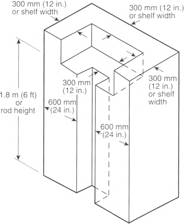
FIGURE 410.16(A) Clothes Closet Storage Space.
(B) Luminaire Types Permitted.
Only luminaires of the following types shall be permitted in a clothes closet:
- Surface-mounted or recessed incandescent or LED luminaires with completely enclosed light sources
- Surface-mounted or recessed fluorescent luminaires
- Surface-mounted fluorescent or LED luminaires identified as suitable for installation within the clothes closet storage space
(C) Luminaire Types Not Permitted.
Incandescent luminaires with open or partially enclosed lamps and pendant luminaires or lampholders shall not be permitted.
(D) Location.
The minimum clearance between luminaires installed in clothes closets and the nearest point of a clothes closet storage space shall be as follows:
- 300 mm (12 in.) for surface-mounted incandescent or LED luminaires with a completely enclosed light source installed on the wall above the door or on the ceiling.
- 150 mm (6 in.) for surface-mounted fluorescent luminaires installed on the wall above the door or on the ceiling.
- 150 mm (6 in.) for recessed incandescent or LED luminaires with a completely enclosed light source installed in the wall or the ceiling.
- 150 mm (6 in.) for recessed fluorescent luminaires installed in the wall or the ceiling.
Exception: Surface-mounted fluorescent or LED luminaires shall be permitted to be installed within the clothes closet storage space where identified for this use.
410.21 Temperature Limit of Conductors in Outlet Boxes.
Luminaires shall be of such construction or installed so that the conductors in outlet boxes shall not be subjected to temperatures greater than that for which the conductors are rated.
Branch-circuit wiring, other than 2-wire or multiwire branch circuits supplying power to luminaires connected together, shall not be passed through an outlet box that is an integral part of a luminaire unless the luminaire is identified for through-wiring.
Informational Note: See 410.64(C) for wiring supplying power to luminaires connected together.
410.22 Outlet Boxes to Be Covered.
In a completed installation, each outlet box shall be provided with a cover unless covered by means of a luminaire canopy, lampholder, receptacle that covers the box or is provided with a faceplate, or similar device.
410.24 Connection of Electric-Discharge and LED Luminaires.
(B) Access to Boxes.
Electric-discharge and LED luminaires surface mounted over concealed outlet, pull, or junction boxes and designed not to be supported solely by the outlet box shall be provided with suitable openings in the back of the luminaire to provide access to the wiring in the box.
410.30 Supports.
(A) General.
Luminaires and lampholders shall be securely supported. A luminaire that weighs more than 3 kg (6 lb) or exceeds 400 mm (16 in.) in any dimension shall not be supported by the screw shell of a lampholder.
(B) Metal or Nonmetallic Poles Supporting Luminaires.
Metal or nonmetallic poles shall be permitted to be used to support luminaires and as a raceway to enclose supply conductors, provided the following conditions are met:
- A pole shall have a handhole not less than 50 mm x 100 mm (2 in. x 4 in.) with a cover suitable for use in wet locations to provide access to the supply terminations within the pole or pole base.Exception No. 1: No handhole shall be required in a pole 2.5 m (8 ft) or less in height abovegrade where the supply wiring method continues without splice or pull point, and where the interior of the pole and any splices are accessible by removing the luminaire.Exception No. 2: No handhole shall be required in a pole 6.0 m (20 ft) or less in height abovegrade that is provided with a hinged base.
- Where raceway risers or cable is not installed within the pole, a threaded fitting or nipple shall be brazed, welded, or attached to the pole opposite the handhole for the supply connection.
- A metal pole shall be provided with an equipment grounding terminal as follows:
- A pole with a handhole shall have the equipment grounding terminal accessible from the handhole.
- A pole with a hinged base shall have the equipment grounding terminal accessible within the base.
- A metal pole with a hinged base shall have the hinged base and pole bonded together.
- Metal raceways or other equipment grounding conductors shall be bonded to the metal pole with an equipment grounding conductor recognized by 250.118 and sized in accordance with 250.122.
- Conductors in vertical poles used as raceway shall be supported as provided in 300.19.
410.36 Means of Support.
(A) Luminaires Supported by Outlet Boxes.
Luminaires shall be permitted to be supported by outlet boxes or fittings installed as required by 314.23. The installation shall comply with the following requirements:
- The outlet boxes or fittings shall comply with 314.27(A)(1) and 314.27(A)(2).
- Luminaires shall be permitted to be supported in accordance with 314.27(E).
- Outlet boxes complying with 314.27(E) shall be considered lighting outlets as required by 210.70(A), (B), and (C).
(B) Suspended Ceilings.
Framing members of suspended ceiling systems used to support luminaires shall be securely fastened to each other and shall be securely attached to the building structure at appropriate intervals. Luminaires shall be securely fastened to the ceiling framing member by mechanical means such as bolts, screws, or rivets. Listed clips identified for use with the type of ceiling framing member(s) and luminaire(s) shall also be permitted.
(D) Insulating Joints.
Insulating joints that are not designed to be mounted with screws or bolts shall have an exterior metal casing, insulated from both screw connections.
(G) Trees.
Outdoor luminaires and associated equipment shall be permitted to be supported by trees.
Informational Note No. 1: See 225.26 for restrictions for support of overhead conductors.
Informational Note No. 2: See 300.5(D) for protection of conductors.
410.40 Equipment Grounding Conductor.
Luminaires and lighting equipment shall be connected to an equipment grounding conductor as required by Part V of this article.
410.42 Luminaire(s) With Exposed Conductive Surfaces.
Exposed conductive surfaces shall be connected to an equipment grounding conductor.
Exception: Exposed conductive surfaces that comply with any of the following shall not be required to be connected to an equipment grounding conductor:
(1) Surfaces separated from all live parts by a listed system of double insulation
(2) Surfaces on small isolated parts, such as mounting screws, clips, and decorative bands on glass spaced at least 38 mm (11/2 in.) from lamp terminals
(3) Surfaces on portable luminaires with a polarized attachment plug
410.44 Connection to the Equipment Grounding Conductor.
Luminaires and equipment that require connection to an equipment grounding conductor in accordance with 410.42 shall be mechanically connected to an equipment grounding conductor.
Exception No. 1: Replacement luminaires shall be permitted to connect an equipment grounding conductor in the same manner as replacement receptacles in compliance with 250.130(C). The luminaire shall then comply with 410.42.
Exception No. 2: Where no equipment grounding conductor exists at the outlet, replacement luminaires that are GECI protected or do not have exposed conductive parts shall not be required to be connected to an equipment grounding conductor.
410.50 Luminaire Wiring - General.
Wiring on or within luminaires shall be neatly arranged and shall not be exposed to physical damage. Excess wiring shall be avoided. Conductors shall be arranged so that they are not subjected to temperatures above those for which they are rated.
410.51 Polarization of Luminaires.
Luminaires shall be wired so that the screw shells of lampholders are connected to the same luminaire or circuit conductor or terminal. The grounded conductor, where connected to a screw shell lampholder, shall be connected to the screw shell.
410.52 Conductor Insulation.
Luminaires shall be wired with conductors having insulation suitable for the environmental conditions, current, voltage, and temperature to which the conductors will be subjected.
410.54 Pendant Conductors for Incandescent Filament Lamps.
(A) Support.
Pendant lampholders with permanently attached leads, where used for other than festoon wiring, shall be hung from separate stranded rubber-covered conductors that are soldered directly to the circuit conductors but supported independently thereof.
(B) Size.
Unless part of listed decorative lighting assemblies, pendant conductors shall not be smaller than 14 AWG for mogul-base or medium-base screw shell lampholders or smaller than 18 AWG for intermediate or candelabra-base lampholders.
(C) Twisted or Cabled.
Pendant conductors longer than 900 mm (3 ft) shall be twisted together where not cabled in a listed assembly.
410.56 Protection of Conductors and Insulation.
(A) Properly Secured.
Conductors shall be secured in a manner that does not tend to cut or abrade the insulation.
(B) Protection Through Metal.
Conductor insulation shall be protected from abrasion where it passes through metal.
(E) Stranding.
Stranded conductors shall be used for wiring on luminaire chains and on other movable or flexible parts.
(F) Tension.
Conductors shall be arranged so that the weight of the luminaire or movable parts does not put tension on the conductors.
410.59 Cord-Connected Showcases.
Individual showcases, other than fixed, shall be permitted to be connected by flexible cord to permanently installed receptacles, and groups of not more than six such showcases shall be permitted to be coupled together by flexible cord and separable locking-type connectors with one of the group connected by flexible cord to a permanently installed receptacle.
The installation shall comply with 410.59(A) through (E).
(A) Cord Requirements.
Flexible cord shall be of the hard-service type, having conductors not smaller than the branch-circuit conductors, having ampacity at least equal to the branch-circuit overcurrent device, and having an equipment grounding conductor.
Informational Note: See Table 250.122 for size of equipment grounding conductor.
(B) Receptacles, Connectors, and Attachment Plugs.
Receptacles, connectors, and attachment plugs shall be of a listed grounding type rated 15 or 20 amperes.
(C) Support.
Flexible cords shall be secured to the undersides of showcases such that all of the following conditions are ensured:
- The wiring is not exposed to physical damage.
- The separation between cases is not in excess of 50 mm (2 in.), or more than 300 mm (12 in.) between the first case and the supply receptacle.
- The free lead at the end of a group of showcases has a female fitting not extending beyond the case.
(E) Secondary Circuit(s).
Where showcases are cord-connected, the secondary circuit(s) of each electric-discharge lighting ballast shall be limited to one showcase.
410.62 Cord-Connected Lampholders and Luminaires.
(A) Lampholders.
Where a metal lampholder is attached to a flexible cord, the inlet shall be equipped with an insulating bushing that, if threaded, is not smaller than metric designator 12 (trade size 3/8). The cord hole shall be of a size appropriate for the cord, and all burrs and fins shall be removed in order to provide a smooth bearing surface for the cord.
Bushing having holes 7 mm (9/32 in.) in diameter shall be permitted for use with plain pendant cord and holes 11 mm (13/32 in.) in diameter with reinforced cord.
(B) Adjustable Luminaires.
Luminaires that require adjusting or aiming after installation shall not be required to be equipped with an attachment plug or cord connector, provided the exposed cord is suitable for hard-usage or extra-hard-usage and is not longer than that required for maximum adjustment. The cord shall not be subject to strain or physical damage.
Informational Note: See Table 400.4, "Use" column for application provisions.
(C) Electric-Discharge and LED Luminaires.
Electric-discharge and LED luminaires shall comply with 410.62(C)(1), (C)(2), and (C)(3), as applicable.
(1) Cord-Connected Installation.
A luminaire or a listed assembly in compliance with any of the conditions in 410.62(C)(1)(a) through (C)(1)(c) shall be permitted to be cord connected provided the luminaire is located directly below the outlet or busway, the cord is not subject to strain or physical damage, and the cord is visible over its entire length except at terminations.
- A luminaire shall be permitted to be connected with a cord terminating in a grounding-type attachment plug or busway plug. If grounding is not required in accordance with 410.42, a polarized-type plug shall be permitted.
- A luminaire assembly equipped with a strain relief and canopy shall be permitted to use a cord connection between the luminaire assembly and the canopy. The canopy shall be permitted to include a section of raceway not over 150 mm (6 in.) in length and intended to facilitate the connection to an outlet box mounted above a suspended ceiling.
- Listed luminaires connected using listed assemblies that incorporate manufactured wiring system connectors in accordance with 604.100(C) shall be permitted to be cord connected.
(2) Provided With Mogul-Base, Screw Shell Lampholders.
Electric-discharge luminaires provided with mogul-base, screw shell lampholders shall be permitted to be connected to branch circuits of 50 amperes or less by cords complying with 240.5. Receptacles and attachment plugs shall be permitted to be of a lower ampere rating than the branch circuit but not less than 125 percent of the luminaire full-load current.
(3) Equipped With Flanged Surface Inlet.
Electric-discharge luminaires equipped with a flanged surface inlet shall be permitted to be supplied by cord pendants equipped with cord connectors. Inlets and connectors shall be permitted to be of a lower ampere rating than the branch circuit but not less than 125 percent of the luminaire load current.
410.64 Luminaires as Raceways.
Luminaires shall not be used as a raceway for circuit conductors unless they comply with 410.64(A), (B), or (C).
(B) Through-Wiring.
Luminaires identified for through-wiring, as permitted by 410.21, shall be permitted to be used as a raceway.
(C) Luminaires Connected Together.
Luminaires designed for end-to-end connection to form a continuous assembly, or luminaires connected together by recognized wiring methods, shall be permitted to contain the conductors of a 2-wire branch circuit, or one multiwire branch circuit, supplying the connected luminaires and shall not be required to be listed as a race-way. One additional 2-wire branch circuit separately supplying one or more of the connected luminaires shall also be permitted.
Informational Note: See Article 100 for the definition of Multiwire Branch Circuit.
410.68 Feeder and Branch-Circuit Conductors and Ballasts.
Feeder and branch-circuit conductors within 75 mm (3 in.) of a ballast, LED driver, power supply, or transformer shall have an insulation temperature rating not lower than 90°C (194°F), unless supplying a luminaire marked as suitable for a different insulation temperature.
410.69 Identification of Control Conductor Insulation.
Where control conductors are spliced, terminated, or connected in the same luminaire or enclosure as the branch-circuit conductors, the field-connected control conductor shall not be of a color reserved for the grounded branch-circuit conductor or the equipment grounding conductor.
Informational Note: See 200.6 for identification of grounded conductor and 250.119 for identification of equipment grounding conductor.
Exception: A field-connected gray-colored control conductor shall be permitted if the insulation is permanently re-identified by marking tape, painting, or other effective means at its termination and at each location where the conductor is visible and accessible. Identification shall encircle the insulation and shall be a color other than white, gray, or green.
410.71 Disconnecting Means for Fluorescent or LED Luminaires That Utilize Double-Ended Lamps.
(1) General.
In indoor locations other than dwellings and associated accessory structures, fluorescent or LED luminaires that utilize double-ended lamps and contain ballast(s) or LED driver(s) that can be serviced in place shall have a disconnecting means either internal or external to each luminaire. For existing installed luminaires without disconnecting means, at the time a ballast or LED driver is added or replaced a disconnecting means shall be installed. The line side terminals of the disconnecting means shall be guarded.
Exception No. 1: A disconnecting means shall not be required for luminaires installed in hazardous (classified) location(s).
Exception No. 2: A disconnecting means shall not be required for luminaires that provide emergency illumination required in 700.16.
Exception No. 3: For cord-and-plug-connected luminaires, an accessible separable connector or an accessible plug and receptacle shall be permitted to serve as the disconnecting means.
Exception No. 4: Disconnecting means shall not be required for every luminaire in a building area if all of the following conditions apply:
(1) More than one luminaire is installed in the building area
(2) The luminaires are not connected to a multiwire branch circuit
(3) The design of the installation includes disconnecting means
(4) The building area will not be left in total darkness should only one disconnect be opened
(2) Multiwire Branch Circuits.
When connected to multiwire branch circuits, the disconnecting means shall simultaneously break all the supply conductors to the ballast, including the grounded conductor.
(3) Location.
The disconnecting means shall be located so as to be accessible to qualified persons before servicing or maintaining the ballast. Where the disconnecting means is external to the luminaire, it shall be a single device, and it shall be attached to the luminaire or the luminaire shall be located within sight of the disconnecting means.
410.80 Luminaire Rating.
(A) Marking.
All luminaires shall be marked with the maximum lamp wattage or electrical rating, manufacturer's name, trademark, or other suitable means of identification. A luminaire requiring supply wire rated higher than 60°C (140°F) shall be marked with the minimum supply wire temperature rating on the luminaire and shipping carton or equivalent.
(B) Electrical Rating.
The electrical rating shall include the voltage and frequency and shall indicate the current rating of the unit, including the ballast, transformer, LED driver, power supply, or autotransformer.
410.82 Portable Luminaires.
Portable luminaires shall be wired with flexible cord recognized by 400.4 and an attachment plug of the polarized or grounding type. If used with Edison-base lampholders, the grounded conductor shall be identified and attached to the screw shell and the identified blade of the attachment plug.
410.90 Screw Shell Type.
Lampholders of the screw shell type shall be installed for use as lampholders only. Where supplied by a circuit having a grounded conductor, the grounded conductor shall be connected to the screw shell.
410.93 Double-Pole Switched Lampholders.
Where supplied by the ungrounded conductors of a circuit, the switching device of lampholders of the switched type shall simultaneously disconnect both conductors of the circuit.
410.97 Lampholders Near Combustible Material.
Lampholders shall be constructed, installed, or equipped with shades or guards so that combustible material is not subjected to temperatures in excess of 90°C (194°F).
410.100 Bases, Incandescent Lamps.
An incandescent lamp for general use on lighting branch circuits shall not be equipped with a medium base if rated over 300 watts, or with a mogul base if rated over 1500 watts. Special bases or other devices shall be used for over 1500 watts.
410.104 Electric-Discharge Lamp Auxiliary Equipment.
(B) Switching.
Where supplied by the ungrounded conductors of a circuit, the switching device of auxiliary equipment shall simultaneously disconnect all conductors.
410.110 General.
Luminaires installed in recessed cavities in walls or ceilings, including suspended ceilings, shall comply with 410.115 through 410.126.
410.115 Temperature.
(A) Combustible Material.
Luminaires shall be installed so that adjacent combustible material will not be subjected to temperatures in excess of 90°C (194°F).
(B) Recessed Incandescent Luminaires.
Incandescent luminaires shall have thermal protection and shall be identified as thermally protected.
Exception No. 1: Thermal protection shall not be required in a recessed luminaire identified for use and installed in poured concrete.
410.116 Clearance and Installation.
(A) Clearance From Combustible Material.
(1) Non-Type IC.
A recessed luminaire that is not identified for contact with insulation shall have all recessed parts spaced not less than 13 mm (1/2 in.) from combustible materials. The points of support and the trim finishing off the openings in the ceiling, wall, or other finished surface shall be permitted to be in contact with combustible materials.
(2) Type IC.
A recessed luminaire that is identified for contact with insulation, Type IC, shall be permitted to be in contact with combustible materials at recessed parts, points of support, and portions passing through or finishing off the opening in the building structure.
(B) Clearance From Thermal Insulation.
Thermal insulation shall not be installed above a recessed luminaire or within 75 mm (3 in.) of the recessed luminaire's enclosure, wiring compartment, ballast, transformer, LED driver, or power supply unless the luminaire is identified as Type IC for insulation contact.
(C) Installation in Fire-Resistant Construction.
Luminaires marked "FOR USE IN NON-FIRE-RATED INSTALLATIONS" shall not be used in fire-rated installations. Where a luminaire is recessed in fire-resistant material in a building of fire-resistant construction, the recessed luminaire shall satisfy one of the following:
- The recessed luminaire shall be listed for use in a fire resistance—rated construction.
- The recessed luminaire shall be installed in or used with a luminaire enclosure that is listed for use in a fire resistance-rated construction.
- The recessed luminaire shall be listed and shall be installed in accordance with a tested fire resistance-rated assembly. When a tested fire resistance-rated assembly allows the installation of a recessed fluorescent luminaire, a recessed LED luminaire of comparable construction shall be permitted.
410.117 Wiring.
(A) General.
Conductors that have insulation suitable for the temperature encountered shall be used.
(B) Circuit Conductors.
Branch-circuit conductors that have an insulation suitable for the temperature encountered shall be permitted to terminate in the luminaire.
(C) Tap Conductors.
Tap conductors of a type suitable for the temperature encountered shall be permitted to run from the luminaire terminal connection to an outlet box placed at least 300 mm (1 ft) from the luminaire. Such tap conductors shall be in suitable raceway or Type AC or MC cable of at least 450 mm (18 in.) but not more than 1.8 m (6 ft) in length.
410.118 Access to Other Boxes.
Luminaires recessed in ceilings, floors, or walls shall not be used to access outlet, pull, or junction boxes or conduit bodies, unless the box or conduit body is an integral part of the listed luminaire.
410.120 Temperature.
Luminaires shall be constructed such that adjacent combustible material is not subject to temperatures in excess of 90°C (194°F).
410.122 Lamp Wattage Marking.
Incandescent lamp luminaires shall be marked to indicate the maximum allowable wattage of lamps. The markings shall be permanently installed, in letters at least 6 mm (1/4 in.) high, and shall be located where visible during relamping.
410.126 Lampholders.
Lampholders of the screw shell type shall be of porcelain or other suitable insulating materials.
410.130 General.
(A) Open-Circuit Voltage of 1000 Volts or Less.
Equipment for use with electric-discharge lighting systems and designed for an open-circuit voltage of 1000 volts or less shall be of a type identified for such service.
(B) Considered as Energized.
The terminals of an electric-discharge lamp shall be considered as energized where any lamp terminal is connected to a circuit of over 300 volts.
(C) Transformers of the Oil-Filled Type.
Transformers of the oil-filled type shall not be used.
(D) Additional Requirements.
In addition to complying with the general requirements for luminaires, such equipment shall comply with Part XII of this article.
(E) Thermal Protection - Fluorescent Luminaires.
(1) Integral Thermal Protection.
The ballast of a fluorescent luminaire installed indoors shall have integral thermal protection. Replacement ballasts shall also have thermal protection integral with the ballast.
(2) Simple Reactance Ballasts.
A simple reactance ballast in a fluorescent luminaire with straight tubular lamps shall not be required to be thermally protected.
(F) High-Intensity Discharge Luminaires.
(1) Recessed.
Recessed high-intensity luminaires designed to be installed in wall or ceiling cavities shall have thermal protection and be identified as thermally protected.
(3) Installed in Poured Concrete.
Thermal protection shall not be required in a recessed high-intensity discharge luminaire identified for use and installed in poured concrete.
(4) Recessed Remote Ballasts.
A recessed remote ballast for a high-intensity discharge luminaire shall have thermal protection that is integral with the ballast and shall be identified as thermally protected.
(5) Metal Halide Lamp Containment.
Luminaires that use a metal halide lamp other than a thick-glass parabolic reflector lamp (PAR) shall be provided with a containment barrier that encloses the lamp, or shall be provided with a physical means that only allows the use of a lamp that is Type O.
Informational Note: See ANSI C78.389, American National Standard for Electric Lamps -High Intensity Discharge, Methods of Measuring Characteristics.
410.134 Direct-Current Equipment.
Luminaires installed on dc circuits shall be equipped with auxiliary equipment and resistors designed for dc operation. The luminaires shall be marked for dc operation.
410.135 Open-Circuit Voltage Exceeding 300 Volts.
Equipment having an open-circuit voltage exceeding 300 volts shall not be installed in dwelling occupancies unless such equipment is designed so that there will be no exposed live parts when lamps are being inserted, are in place, or are being removed.
410.136 Luminaire Mounting.
(A) Exposed Components.
Luminaires that have exposed ballasts, transformers, LED drivers, or power supplies shall be installed such that ballasts, transformers, LED drivers, or power supplies shall not be in contact with combustible material unless listed for such condition.
(B) Combustible Low-Density Cellulose Fiberboard.
Where a surface-mounted luminaire containing a ballast, transformer, LED driver, or power supply is to be installed on combustible low-density cellulose fiberboard, it shall be marked for this condition or shall be spaced not less than 38 mm (11/2 in.) from the surface of the fiberboard. Where such luminaires are partially or wholly recessed, 410.110 through 410.126 shall apply.
Informational Note: See ASTM E84-20, Standard Test Method for Surface Burning Characteristics of Building Materials, or ANSI/UL 723-2018, Standard for Test for Surface Burning Characteristics of Building Materials. Combustible low-density cellulose fiberboard includes sheets, panels, and tiles that have a density of 320 kg/m3 (20 lb/ft3) or less and that are formed of bonded plant fiber material but does not include solid or laminated wood or fiberboard that has a density in excess of 320 kg/m3 (20 lb/ft3) or is a material that has been integrally treated with fire-retarding chemicals to the degree that the flame spread index in any plane of the material will not exceed 25, determined in accordance with tests for surface burning characteristics of building materials.
410.137 Equipment Not Integral With Luminaire.
(B) Separate Mounting.
Separately mounted ballasts, transformers, LED drivers, or power supplies that are listed for direct connection to a wiring system shall not be required to be additionally enclosed.
(C) Wired Luminaire Sections.
Wired luminaire sections are paired, with a ballast(s) or LED driver(s) supplying a light source or light sources in both. For interconnection between paired units, it shall be permissible to use metric designator 12 (trade size 3/8) flexible metal conduit in lengths not exceeding 7.5 m (25 ft), installed in accordance with Part II of Article 348. Luminaire wire operating at line voltage, supplying only the ballast(s) or LED driver(s) of one of the paired luminaires, shall be permitted in the same raceway as the light source supply wires of the paired luminaires where the voltage rating of the light source supply wires is greater than the line voltage.
410.140 General.
(A) Listing.
Electric-discharge lighting systems with an open-circuit voltage exceeding 1000 volts shall be listed and installed in conformance with that listing.
(C) Live Parts.
The terminal of an electric-discharge lamp shall be considered as a live part.
(D) Additional Requirements.
In addition to complying with the general requirements for luminaires, such equipment shall comply with Part XIII of this article.
410.141 Control.
(A) Disconnection.
Luminaires or lamp installation shall be controlled either singly or in groups by an externally operable switch or circuit breaker that opens all ungrounded primary conductors.
(B) Within Sight or Locked Type.
The switch or circuit breaker shall be located within sight from the luminaires or lamps, or it shall be permitted to be located elsewhere if it is lockable open in accordance with 110.25.
410.142 Lamp Terminals and Lampholders.
Parts that must be removed for lamp replacement shall be hinged or held captive. Lamps or lampholders shall be designed so that there are no exposed live parts when lamps are being inserted or removed.
410.143 Transformers.
(B) Voltage.
The secondary circuit voltage shall not exceed 15,000 volts, nominal, under any load condition. The voltage to ground of any output terminals of the secondary circuit shall not exceed 7500 volts under any load conditions.
(C) Rating.
Transformers shall have a secondary short-circuit current rating of not more than 150 mA if the open-circuit voltage is over 7500 volts, and not more than 300 mA if the open-circuit voltage rating is 7500 volts or less.
(D) Secondary Connections.
Secondary circuit outputs shall not be connected in parallel or in series.
410.144 Transformer Locations.
(A) Accessible.
Transformers shall be accessible after installation.
(B) Secondary Conductors.
Transformers shall be installed as near to the lamps as practicable to keep the secondary conductors as short as possible.
(C) Adjacent to Combustible Materials.
Transformers shall be located so that adjacent combustible materials are not subjected to temperatures in excess of 90°C (194°F).
410.145 Exposure to Damage.
Lamps shall not be located where normally exposed to physical damage.
410.146 Marking.
Each luminaire or each secondary circuit of tubing having an open-circuit voltage of over 1000 volts shall have a clearly legible marking in letters not less than 6 mm (1/4 in.) high reading "Caution _____ volts." The voltage indicated shall be the rated open-circuit voltage. The caution sign(s) or label(s) shall comply with 110.21 (B).
410.150 Installation.
(A) Lighting Track.
Lighting track shall be permanently installed and permanently connected to a branch circuit. Only lighting track fittings shall be installed on lighting track. Lighting track fittings shall not be equipped with general-purpose receptacles.
(B) Connected Load.
The connected load on lighting track shall not exceed the rating of the track. Lighting track shall be supplied by a branch circuit having a rating not more than that of the track. The load calculation in 220.46(B) shall not be required to limit the length of track on a single branch circuit, and it shall not be required to limit the number of luminaires on a single track.
(C) Locations Not Permitted.
Lighting track shall not be installed in the following locations:
- Where likely to be subjected to physical damage
- In wet or damp locations
- Where subject to corrosive vapors
- In storage battery rooms
- In hazardous (classified) locations
- Where concealed
- Where extended through walls or partitions
- Less than 1.5 m (5 ft) above the finished floor except where protected from physical damage or track operating at less than 30 volts rms open-circuit voltage
- Where prohibited by 410.10(D)
(D) Support.
Fittings identified for use on lighting (rack shall be designed specifically for the track on which they are to be installed. They shall be securely fastened to the track, shall maintain polarization and connections to the equipment grounding conductor, and shall be designed to be suspended directly from the track.
410.153 Heavy-Duty Lighting Track.
Heavy-duty lighting track is lighting track identified for use exceeding 20 amperes. Each fitting attached to a heavy-duty lighting track shall have individual overcurrent protection.
410.154 Fastening.
Lighting track shall be securely mounted so that each fastening is suitable for supporting the maximum weight of luminaires that can be installed. Unless identified for supports at greater intervals, a single section 1.2 m (4 ft) or shorter in length shall have two supports, and, where installed in a continuous row, each individual section of not more than 1.2 m (4 ft) in length shall have one additional support.
410.155 Construction Requirements.
(A) Construction.
The housing for the lighting track system shall be of substantial construction to maintain rigidity. The conductors shall be installed within the track housing, permitting insertion of a luminaire, and designed to prevent tampering and accidental contact with live parts. Components of lighting track systems of different voltages shall not be interchangeable. The track conductors shall be a minimum 12 AWG or equal and shall be copper. The track system ends shall be insulated and capped.
(B) Equipment Grounding Conductor.
Lighting track shall be connected to the equipment grounding conductor in accordance with Part V of this article, and the track sections shall be securely coupled to maintain continuity of the circuitry, polarization, and grounding throughout.
410.160 Listing of Decorative Lighting.
Decorative lighting and similar accessories used for holiday lighting and similar purposes, in accordance with 590.3(B), shall be listed.
410.170 General.
Luminaires complying with Parts, I, II, III, IV, V, VI, VII, IX, X, XI, and XII of this article shall be permitted to be used for horticultural lighting. Part XVI shall additionally apply to lighting equipment specifically identified for horticultural use.
Informational Note: Lighting equipment identified for horticultural use is designed to provide a spectral characteristic needed for the growth of plants and can also provide supplemental general illumination within the growing environment.
410.174 Installation and Use.
Lighting equipment identified for horticultural use shall be installed and used in accordance with the manufacturer's installation instructions and installation markings on the equipment as required by that listing.
410.176 Locations Not Permitted.
(A) General Lighting.
Lighting equipment identified for horticultural use shall not be installed as lighting for general illumination unless such use is indicated in the manufacturer's instructions.
(B) Installed Location.
Lighting equipment identified for horticultural use shall not be installed where it is likely to be subject to physical damage or where concealed.
410.178 Flexible Cord.
Flexible cord shall only be permitted when provided as part of listed lighting equipment identified for horticultural use for any of the following uses:
- Connecting a horticultural lighting luminaire directly to a branch circuit outlet
- Interconnecting horticultural lighting luminaires
- Connecting a horticultural lighting luminaire to a remote power source
Informational Note: Remote power sources include LED drivers, fluorescent ballasts, or HID ballasts.
410.180 Fittings and Connectors.
Fittings and connectors attached to flexible cords shall be provided as part of a listed horticultural lighting equipment device or system and installed in accordance with the instructions provided as part of that listing.
410.182 Equipment Grounding Conductor.
Lighting equipment identified for horticultural use shall be connected to the equipment grounding conductor in accordance with Part V of this article.
410.184 Ground-Fault Circuit-Interrupter (GFCI) Protection and Special Purpose Ground-Fault Circuit-Interrupter (SPGFCI) Protection.
Lighting equipment identified for horticultural use and employing flexible cord(s) with one or more separable connector(s) or attachment plug(s) shall be supplied by lighting outlets protected by a listed GFCI.
Exception: Circuits exceeding 150 volts to ground shall be protected by a listed SPGFCI.
Informational Note: See UL 943C, Outline of Investigation for Special Purpose Ground-Fault Circuit-Interrupters, for information on special purpose ground-fault circuit interrupters.
410.191 Listing.
Luminaires intended to emit germicidal irradiation shall be listed and identified as germicidal equipment.
410.193 Installation.
Luminaires shall be installed in accordance with the manufacturer's instructions and equipment markings.
410.195 Locations Not Permitted.
(A) General Lighting.
Luminaires shall not be installed as lighting for general illumination unless such use is indicated in the manufacturer's instructions.
(B) Installed Location.
Luminaires shall not be installed where likely to be subject to physical damage.
(D) Mounting Height.
Luminaires installed in a building space that will be occupied during luminaire operation shall not be mounted below the minimum height specified by its listing and installation instructions.
410.197 Germicidal Irradiation Systems.
(B) System Components.
All system components shall be provided by the system manufacturer or clearly specified in the installation instructions as a component that the installer is required to source separately.
(C) Installation.
A germicidal irradiation system shall be installed in accordance with the manufacturer's installation instructions and installation markings.
(D) Dwellings.
A germicidal irradiation system shall not be installed in a dwelling unless listed and identified for use in dwellings.
Article 411
Low-Voltage Lighting
411.1 Scope.
This article covers low voltage lighting systems and their associated components.
411.2 Reconditioned Equipment.
Listed low-voltage lighting systems or a lighting system assembled from listed parts shall not be reconditioned.
(A) Listed System.
The luminaires, power supply, and luminaire fittings (including the exposed bare conductors) of a low-voltage lighting system shall be listed for use as part of the same identified lighting system.
(B) Assembly of Listed Parts.
A lighting system assembled from the following listed parts shall be permitted:
- Low-voltage luminaires identified for the use
- Power supply identified for the use
- Low-voltage luminaire fittings identified for the use
- Suitably rated cord or cable, or any Chapter 3 wiring method for the secondary circuit
411.3 Voltage Limitations.
411.4 Low-Voltage Lighting Systems.
Low voltage lighting systems shall consist of an isolating power supply, low-voltage luminaires, and associated equipment that are all identified for the use. The output circuits of the power supply shall be rated for 25 amperes maximum under all load conditions.
411.6 Specific Location Requirements.
(B) Pools, Spas, Fountains, and Similar Locations.
Lighting systems shall be installed not less than 3 m (10 ft) horizontally from the nearest edge of the water, unless permitted elsewhere in this Code.
411.7 Secondary Circuits.
(A) Grounding.
Secondary circuits shall not be grounded.
Exception: Secondary circuits supplied by a Class 2 power source listed and identified as suitable for secondary grounding shall be permitted to be grounded.
(C) Bare Conductors.
Exposed bare conductors and current-carrying parts shall be permitted for indoor installations only. Bare conductors shall not be installed less than 2.1 m (7 ft) above the finished floor, unless specifically listed for a lower installation height.
411.8 Branch Circuit.
Lighting systems covered by this article shall be supplied from a maximum 20-ampere branch circuit.
Article 422
Appliances
422.5 GFCI Protection.
(A) General.
Appliances identified in 422.5(A)(1) through (A)(7) 150 volts or less to ground and 60 amperes or less, single- or 3-phase, shall be provided with Class A protection for personnel. Multiple Class A protective devices shall be permitted but shall not be required.
- Automotive vacuum machines
- Drinking water coolers and bottle fill stations
- Cord-and-plug-connected high-pressure spray washing machines
- Tire inflation machines
- Vending machines
- Sump pumps
- Dishwashers
Informational Note: Section 210.8 specifies requirements for GFCI protection for the branch-circuit outlet where the covered location warrants such protection.
(B) Type and Location.
The GFCI shall be readily accessible, listed, and located in one or more of the following locations:
- Within the branch-circuit overcurrent device
- A device or outlet within the supply circuit
- An integral part of the attachment plug
- Within the supply cord not more than 300 mm (12 in.) from the attachment plug
- Factory installed within the appliance
422.10 Branch Circuits.
(A) Individual Branch Circuits.
Individual branch circuits supplying appliances shall comply with the following as applicable:
- The ampacities of branch-circuit conductors shall not be less than the marked rating of the appliance or the marked rating of an appliance having combined loads.
- The ampacities of branch-circuit conductors for motor-operated appliances not having a marked rating shall be in accordance with Part II of Article 430.
- The branch-circuit rating for an appliance that is a continuous load, other than a motor-operated appliance, shall not be less than 125 percent of the marked rating, or not less than 100 percent of the marked rating if the branch-circuit device and its assembly are listed for continuous loading at 100 percent of its rating.
- Branch circuits and branch-circuit conductors for household ranges and cooking appliances shall be permitted to be in accordance with Table 220.55 and shall be sized in accordance with 210.19(C).
(B) Branch Circuits Supplying Two or More Loads.
For branch circuits supplying appliances and other loads, the rating shall be determined in accordance with 210.23.
422.11 Overcurrent Protection.
Appliances shall be protected against overcurrent in accordance with 422.11(A) through (G) and 422.10.
(A) Branch-Circuit Overcurrent Protection.
Branch circuits shall be protected in accordance with 240.4.
If a protective device rating is marked on an appliance, the branch-circuit overcurrent device rating shall not exceed the protective device rating marked on the appliance.
(B) Household-Type Appliances With Surface Heating Elements.
Household-type appliances with surface heating elements having a maximum demand of more than 60 amperes calculated in accordance with Table 220.55 shall have their power supply subdivided into two or more circuits, each of which shall be provided with overcurrent protection rated at not over 50 amperes.
(C) Infrared Lamp Commercial and Industrial Heating Appliances.
Infrared lamp commercial and industrial heating appliances shall have overcurrent protection not exceeding 50 amperes.
(D) Open-Coil or Exposed Sheathed-Coil Types of Surface Heating Elements in Commercial-Type Heating Appliances.
Open-coil or exposed sheathed-coil types of surface heating elements in commercial-type heating appliances shall be protected by overcurrent protective devices rated at not over 50 amperes.
(E) Single Non-Motor-Operated Appliance.
If the branch circuit supplies a single non-motor-operated appliance, the rating of overcurrent protection shall comply with the following:
- Not exceed the overcurrent protection rating marked on the appliance.
- Not exceed 20 amperes if the overcurrent protection rating is not marked and the appliance is rated 13.3 amperes or less.
- Not exceed 150 percent of the appliance rated current if the overcurrent protection rating is not marked and the appliance is rated over 13.3 amperes. Where 150 percent of the appliance rating does not correspond to a standard overcurrent device ampere rating, the next higher standard rating shall be permitted.
(F) Electric Heating Appliances Employing Resistance-Type Heating Elements Rated More Than 48 Amperes.
(1) Electric Heating Appliances.
Electric heating appliances employing resistance-type heating elements rated more than 48 amperes, other than household appliances with surface heating elements covered by 422.11(B), and commercial-type heating appliances covered by 422.11(D), shall have the heating elements subdivided. Each subdivided load shall not exceed 48 amperes, and each subdivided load shall be protected at not more than 60 amperes.
These supplementary overcurrent protective devices shall be (1) factory-installed within or on the heater enclosure or provided as a separate assembly by the heater manufacturer; (2) accessible; and (3) suitable for branch-circuit protection.
The main conductors supplying these overcurrent protective devices shall be considered branch-circuit conductors.
(2) Commercial Kitchen and Cooking Appliances.
Commercial kitchen and cooking appliances using sheathed-type heating elements not covered in 422.11 (D) shall be permitted to be subdivided into circuits not exceeding 120 amperes and protected at not more than 150 amperes where one of the following is met:
- Elements are integral with and enclosed within a cooking surface.
- Elements are completely contained within an enclosure identified as suitable for this use.
- Elements are contained within an ASME-rated and stamped vessel.
(3) Water Heaters and Steam Boilers.
Resistance-type immersion electric heating elements shall be permitted to be subdivided into circuits not exceeding 120 amperes and protected at not more than 150 amperes as follows:
- Where contained in ASME-rated and stamped vessels
- Where included in listed instantaneous water heaters
- Where installed in low-pressure water heater tanks or open-outlet water heater vessels
Informational Note: See IEC 60335-2-21, Household and similar electrical appliances - Safety - Particular requirements for storage water heaters, for information on low-pressure and open-outlet heaters are atmospheric pressure water heaters
(G) Motor-Operated Appliances.
Motors of motor-operated appliances shall be provided with overload protection in accordance with Part III of Article 430. Hermetic refrigerant motor-compressors in air-conditioning or refrigerating equipment shall be provided with overload protection in accordance with Part VI of Article 440. Where appliance overcurrent protective devices that are separate from the appliance are required, data for selection of these devices shall be marked on the appliance. The minimum marking shall be that specified in 430.7 and 440.4.
422.12 Central Heating Equipment.
Central heating equipment other than fixed electric space-heating equipment shall be supplied by an individual branch circuit.
Exception No. 1: Auxiliary equipment, such as a pump, valve, humidifier, or electrostatic air cleaner directly associated with the heating equipment, shall be permitted to be connected to the same branch circuit.
Exception No. 2: Permanently connected air-conditioning equipment shall be permitted to be connected to the same branch circuit.
422.13 Storage-Type Water Heaters.
The branch-circuit over-current device and conductors for fixed storage-type water heaters that have a capacity of 450 L (120 gal) or less shall have an ampere rating of not less than 125 percent of the ampere rating of the water heater.
Informational Note: See 422.10 for branch-circuit rating.
422.16 Flexible Cords.
(A) General.
Flexible cord shall be permitted as follows:
- To connect appliances to facilitate their frequent interchange or to prevent the transmission of noise or vibration.
- To facilitate the removal or disconnection of appliances that are fastened in place, where the fastening means and mechanical connections are specifically designed to permit ready removal for maintenance or repair and the appliance is intended or identified for flexible cord connection.
- All cord-and-plug-connected electrically heated appliances that produce temperatures in excess of 121°C (250°F) on surfaces with which the cord is likely to be in contact shall be provided with one of the types of heater cords listed in Table 400.4.
(B) Specific Appliances.
(1) Electrically Operated In-Sink Waste Disposers.
Electrically operated in-sink waste disposers shall be permitted to be cord-and-plug-connected with a flexible cord identified as suitable in the installation instructions of the appliance manufacturer where all of the following conditions are met:
- The length of the cord is not less than 450 mm (18 in.) and not exceeding 900 mm (36 in.).
- Receptacles are located to protect against physical damage to the flexible cord.
- The receptacle is accessible.
- The flexible cord has an equipment grounding conductor and is terminated with a grounding-type attachment plug.
Exception: A listed appliance distinctly marked to identify it as protected by a system of double insulation shall not be required to be terminated with a grounding-type attachment plug.
(2) Built-In Dishwashers and Trash Compactors.
Built-in dish-washers and trash compactors shall be permitted to be cord-and-plug-connected with a flexible cord identified as suitable for the purpose in the installation instructions of the appliance manufacturer where all of the following conditions are met:
- For a trash compactor, the length of the cord is not less than 0.9 m (3 ft) and not exceeding 1.2 m (4 ft) measured from the face of the attachment plug to the plane of the rear of the appliance.
- For a built-in dishwasher, the length of the cord is not less than 0.9 m (3 ft) and not exceeding 2.0 m (6.5 ft) measured from the face of the attachment plug to the plane of the rear of the appliance.
- Receptacles are located to protect against physical damage to the flexible cord.
- The receptacle for a trash compactor is located in the space occupied by the appliance or adjacent thereto. If a flexible cord passes through an opening, it shall be protected against damage by a bushing, grommet, smoothed edge, or other approved means.
- The receptacle for a built-in dishwasher is located in the space adjacent to the space occupied by the dishwasher. If a flexible cord passes through an opening, it shall be protected against damage by a bushing, grommet, smoothed edge, or other approved means.
- The receptacle is accessible.
- The flexible cord has an equipment grounding conductor that is terminated with a grounding-type attachment plug.
Exception: A listed appliance distinctly marked to identify it as protected by a system of double insulation shall not be required to be terminated with a grounding-type attachment plug.
(3) Wall-Mounted Ovens and Counter-Mounted Cooking Units.
Wall-mounted ovens and counter-mounted cooking units complete with provisions for mounting and for making electrical connections shall be permitted to be permanently connected or cord-and-plug-connected with a flexible cord identified as suitable for the purpose in the installation instructions of the appliance manufacturer.
A separable connector or a plug and receptacle combination in the supply line to an oven or cooking unit shall be identified for the temperature of the space in which it is located.
(4) Range Hoods and Microwave Oven/Range Hood Combinations.
Range hoods and over-the-range microwave ovens with integral range hoods shall be permitted to be cord-and-plug-connected with a flexible cord identified as suitable for use on range hoods in the installation instructions of the appliance manufacturer, where all of the following conditions are met:
- The length of the cord is not less than 450 mm (18 in.) and not exceeding 1.2 m (4 ft).
- Receptacles are located to protect against physical damage to the flexible cord.
- The receptacle is supplied by an individual branch circuit.
- The receptacle is accessible.
- The flexible cord has an equipment grounding conductor and is terminated with a grounding-type attachment plug.
Exception: A listed appliance distinctly marked to identify it as protected by a system of double insulation shall not be required to be terminated with a grounding-type attachment plug.
422.18 Ceiling-Suspended (Paddle) Fans.
(A) Support.
Ceiling-suspended (paddle) fans shall be supported independently of an outlet box or by one of the following:
- A listed outlet box or listed outlet box system identified for fan support installed in accordance with 314.27(C)
- A listed outlet box system, a listed weight-supporting ceiling receptacle, and a compatible factory-installed weight-supporting attachment fitting that is installed in accordance with 314.27(E)
(B) Location.
No metal parts of ceiling-suspended (paddle) fans in bathrooms and shower spaces shall be located within a zone measured 900 mm (3 ft) horizontally and 2.5 m (8 ft) vertically from the top of the bathtub rim or shower stall threshold. This zone is all-encompassing and shall include the space directly over the tub or shower stall.
422.20 Outlet Boxes to Be Covered.
In a completed installation, each outlet box shall be provided with a cover unless covered by means of a ceiling-suspended (paddle) fan canopy.
422.21 Covering of Combustible Material at Outlet Boxes.
Any combustible ceiling finish that is exposed between the edge of a ceiling-suspended (paddle) fan canopy or pan and an outlet box and that has a surface area of 1160 mm2 (180 in.2) or more shall be covered with noncombustible material.
422.22 Utilizing Separable Attachment Fittings.
Appliances shall be permitted to use listed weight-supporting ceiling receptacles in combination with compatible weight-supporting attachment fittings used within their ratings and used in accordance with 314.27(E).
422.30 General.
A means shall be provided to simultaneously disconnect each appliance from all ungrounded conductors in accordance with the following sections of Part III. If an appliance is supplied by more than one branch circuit or feeder, these disconnecting means shall be grouped and identified as being the multiple disconnecting means for the appliance. Each disconnecting means shall simultaneously disconnect all ungrounded conductors that it controls.
422.31 Disconnection of Permanently Connected Appliances.
For appliances that do not have a disconnecting means in accordance with 422.33 or 422.34, a disconnecting means shall be provided in accordance with 422.31(A), (B), or (C).
(A) Rated at Not over 300 Volt-Amperes or 1/8 Horsepower.
For permanently connected appliances rated at not over 300 voltamperes or 1/8 hp, the branch-circuit overcurrent device shall be permitted to serve as the disconnecting means where the switch or circuit breaker is within sight from the appliance or be capable of being locked in the open position in compliance with 110.25.
(B) Appliances Rated Over 300 Volt-Amperes.
For permanently connected appliances rated over 300 volt-amperes, the branch-circuit switch or circuit breaker shall be permitted to serve as the disconnecting means where the switch or circuit breaker is within sight from the appliance or be capable of being locked in the open position in compliance with 110.25.
Informational Note: See 422.34 for appliances employing unit switches.
(C) Motor-Operated Appliances Rated over 1/8 Horsepower.
The disconnecting means shall comply with 430.109 and 430.110. For permanently connected motor-operated appliances with motors rated over 1/8 hp, the disconnecting means shall be within sight from the appliance or be capable of being locked in the open position in compliance with 110.25.
Exception: If an appliance is provided with a unit switch that complies with 422.34(A), (B), or (C), the switch or circuit breaker serving as the other disconnecting means shall be permitted to be out of sight from the appliance.
422.33 Disconnection of Cord-and-Plug-Connected or Attachment Fitting-Connected Appliances.
(A) Separable Connector or an Attachment Plug (or Attachment Fitting) and Receptacle.
For cord-and-plug- (or attachment fitting—) connected appliances, an accessible separable connector or an accessible plug (or attachment fitting) and receptacle combination shall be permitted to serve as the disconnecting means. The attachment fitting shall be a factory installed part of the appliance and suitable for disconnection of the appliance. Where the separable connector or plug (or attachment fitting) and receptacle combination are not accessible, cord-and-plug-connected or attachment fitting-and-plug-connected appliances shall be provided with disconnecting means in accordance with 422.31.
(B) Connection at the Rear Base of a Range.
For cord-and-plug-connected household electric ranges, an attachment plug and receptacle connection at the rear base of a range, accessible from the front by removal of a drawer, shall be permitted.
(C) Rating.
The rating of a receptacle or of a separable connector shall not be less than the rating of any appliance connected thereto.
Exception: Demand factors authorized elsewhere in this Code shall be permitted to be applied to the rating of a receptacle or of a separable connector.
422.34 Unit Switch(es) as Disconnecting Means.
A unit switch(es) with a marked-off position that is a part of an appliance and disconnects all ungrounded conductors shall be permitted as the disconnecting means required by this article where other means for disconnection are provided in occupancies specified in 422.34(A) through (D).
(A) Multifamily Dwellings.
In multifamily dwellings, the other disconnecting means shall be within the dwelling unit, or on the same floor as the dwelling unit in which the appliance is installed, and shall be permitted to control lamps and other appliances.
(B) Two-Family Dwellings.
In two-family dwellings, the other disconnecting means shall be permitted either inside or outside of the dwelling unit in which the appliance is installed. In this case, an individual switch or circuit breaker for the dwelling unit shall be permitted and shall also be permitted to control lamps and other appliances.
(C) One-Family Dwellings.
In one-family dwellings, the service disconnecting means shall be permitted to be the other disconnecting means.
(D) Other Occupancies.
In other occupancies, the branch-circuit switch or circuit breaker, where readily accessible for servicing of the appliance, shall be permitted as the other disconnecting means.
422.40 Polarity in Cord-and-Plug-Connected Appliances.
If the appliance is provided with a manually operated, line-connected, single-pole switch for appliance on-off operation, an Edison-base lampholder, or a 15- or 20-ampere receptacle, the attachment plug shall be of the polarized or grounding type.
A 2-wire, nonpolarized attachment plug shall be permitted to be used on a listed double-insulated shaver.
Informational Note: See 410.82 for polarity of Edison-base lampholders.
422.41 Cord-and-Plug-Connected Appliances Subject to Immersion.
Cord-and-plug-connected portable, freestanding hydromassage units and hand-held hair dryers shall be constructed to provide protection for personnel against electrocution when immersed.
422.42 Signals for Heated Appliances.
In other than dwelling-type occupancies, each electrically heated appliance or group of appliances intended to be applied to combustible material shall be provided with a signal or an integral temperature-limiting device.
422.44 Cord-and-Plug-Connected Immersion Heaters.
Electric heaters of the cord-and-plug-connected immersion type shall be constructed and installed so that current-carrying parts are effectively insulated from electrical contact with the substance in which they are immersed.
422.47 Water Heater Controls.
All storage or instantaneous-type water heaters shall be equipped with a temperature-limiting means in addition to its control thermostat to disconnect all ungrounded conductors. Such means shall comply with both of the following:
- Installed to sense maximum water temperature.
- Be either a trip-free, manually reset type or a type having a replacement element.
Exception No. 1: Storage water heaters that are identified as being suitable for use with a supply water temperature of 82°C (180°F) or above and a capacity of 60 kW or above.
Exception No. 2: Instantaneous-type water heaters that are identified as being suitable for such use, with a capacity of 4 L (1 gal) or less.
422.48 Infrared Lamp Industrial Heating Appliances.
(A) 300 Watts or Less.
Infrared heating lamps rated at 300 watts or less shall be permitted with lampholders of the medium-base, unswitched porcelain type or other types identified as suitable for use with infrared heating lamps rated 300 watts or less.
(B) Over 300 Watts.
Screw shell lampholders shall not be used with infrared lamps rated over 300 watts, unless the lampholders are identified as being suitable for use with infrared heating lamps rated over 300 watts.
422.60 Nameplate.
(A) Nameplate Marking.
Each electrical appliance shall be provided with a nameplate giving the identifying name and the rating in volts and amperes, or in volts and watts. If the appliance is to be used on a specific frequency or frequencies, it shall be so marked.
Where motor overload protection external to the appliance is required, the appliance shall be so marked.
Informational Note: See 422.11 for overcurrent protection requirements.
(B) To Be Visible.
Marking shall be located so as to be visible or easily accessible after installation.
422.61 Marking of Heating Elements.
All heating elements that are rated over one ampere, replaceable in the field, and a part of an appliance shall be legibly marked with the ratings in volts and amperes, or in volts and watts, or with the manufacturer's part number.
422.62 Appliances Consisting of Motors and Other Loads.
(A) Nameplate Horsepower Markings.
Where a motor-operated appliance nameplate includes a horsepower rating, that rating shall not be less than the horsepower rating on the motor nameplate. Where an appliance consists of multiple motors, or one or more motors and other loads, the nameplate value shall not be less than the equivalent horsepower of the combined loads, calculated in accordance with 430.110(C)(1).
(B) Additional Nameplate Markings.
Appliances, other than those factory-equipped with cords and attachment plugs and with nameplates in compliance with 422.60, shall be marked in accordance with 422.62(B)(1) or (B)(2).
(1) Marking.
In addition to the marking required in 422.60, the marking on an appliance consisting of a motor with other load(s) or motors with or without other load(s) shall specify the minimum supply circuit conductor ampacity and the maximum rating of the circuit overcurrent protective device. This requirement shall not apply to an appliance with a nameplate in compliance with 422.60 where both the minimum supply circuit conductor ampacity and maximum rating of the circuit overcurrent protective device are not more than 15 amperes.
(2) Alternate Marking Method.
An alternate marking method shall be permitted to specify the rating of the largest motor in volts and amperes, and the additional load(s) in volts and amperes, or volts and watts in addition to the marking required in 422.60. The ampere rating of a motor 1/8 horsepower or less or a nonmotor load 1 ampere or less shall be permitted to be omitted unless such loads constitute the principal load.
Article 424
Fixed Electric Space-Heating Equipment
424.1 Scope.
This article covers fixed electric equipment used for space heating. For the purpose of this article, heating equipment includes heating cables, unit heaters, boilers, central heating systems, or other fixed electric space-heating equipment. This article does not apply to process heating and room air conditioning.
424.3 Other Articles.
Fixed electric space-heating equipment incorporating a hermetic refrigerant motor-compressor shall additionally comply with Table 424.3 unless amended by this article.
424.4 Branch Circuits.
(A) Branch-Circuit Requirements.
An individual branch circuit shall be permitted to supply any volt-ampere or wattage rating of fixed electric space-heating equipment for which the branch circuit is rated.
Branch circuits supplying two or more outlets for fixed electric space-heating equipment shall be rated not over 30 amperes. In other than a dwelling unit, fixed infrared heating equipment shall be permitted to be supplied from branch circuits rated not over 50 amperes.
(B) Branch-Circuit Conductor Sizing.
The branch-circuit conductor(s) ampacity shall not be less than 125 percent of the load of the fixed electric space-heating equipment and any associated motor(s).
424.6 Listed Equipment.
Electric baseboard heaters, heating cables, duct heaters, and radiant heating systems shall be listed and labeled.
424.10 General.
Factory-installed receptacle outlets that are part of a permanently installed electric baseboard heater, or outlets provided as a separate listed assembly of an electric baseboard heater, shall be permitted in lieu of a receptacle outlet(s) that is required by 210.52. Such receptacle outlets shall not be connected to the baseboard heater circuits.
Informational Note: Listed baseboard heaters include instructions that may not permit their installation below receptacle outlets.
424.11 Supply Conductors.
Fixed electric space-heating equipment requiring supply conductors with an insulation rating greater than 60°C shall be clearly and permanently marked. This marking shall be plainly visible after installation and shall be permitted to be adjacent to the field connection box.
424.12 Locations.
(A) Exposed to Physical Damage.
Where subject to physical damage, fixed electric space-heating equipment shall be protected in an approved manner.
424.13 Spacing From Combustible Materials.
Fixed electric space-heating equipment shall be installed to provide the required spacing between the equipment and adjacent combustible material, unless it is listed to be installed in direct contact with combustible material.
424.19 Disconnecting Means.
Means shall be provided to simultaneously disconnect the heater, motor controller(s), and supplementary overcurrent protective device(s) of all fixed electric space-heating equipment from all ungrounded conductors. Where heating equipment is supplied by more than one source, feeder, or branch circuit, the disconnecting means shall be grouped and identified as having multiple disconnecting means. Each disconnecting means shall simultaneously disconnect all ungrounded conductors that it controls. The disconnecting means specified in 424.19(A) and (B) shall have an ampere rating not less than 125 percent of the total load of the motors and the heaters and shall be capable of being locked in the open position in compliance with 110.25.
(A) Heating Equipment With Supplementary Overcurrent Protection.
The disconnecting means for fixed electric space-heating equipment with supplementary overcurrent protection shall be within sight from the supplementary overcurrent protective device(s), on the supply side of these devices, if fuses, and, in addition, shall comply with either 424.19(A)(1) or (A)(2).
(1) Heater Containing No Motor Rated over 1/8 Horsepower.
The disconnecting means provided shall be within sight from the motor controller(s) and the heater, or shall be lockable as specified in 424.19, or shall be a unit switch complying with 424.19(C).
(2) Heater Containing a Motor(s) Rated over 1/8 Horsepower.
The disconnecting means required by 424.19 shall be permitted to serve as the required disconnecting means for both the motor controller(s) and heater under either of the following conditions:
- Where the disconnecting means is in sight from the motor controller(s) and the heater and complies with Part IX of Article 430.
- Where a motor(s) of more than 1/8 hp and the heater are provided with a single unit switch that complies with 422.34(A), (B), (C), or (D), the disconnecting means shall be permitted to be out of sight from the motor controller.
(B) Heating Equipment Without Supplementary Overcurrent Protection.
(1) Without Motor or with Motor Not over 1/8 Horsepower.
For fixed electric space-heating equipment without a motor rated over 1/8 hp, the branch-circuit switch or circuit breaker shall be permitted to serve as the disconnecting means where the switch or circuit breaker is within sight from the heater or is capable of being locked in the open position in compliance with 110.25.
(2) Over 1/8 Horsepower.
For motor-driven electric space-heating equipment with a motor rated over 1/8 hp, a disconnecting means shall be located within sight from the motor controller or shall be permitted to comply with the requirements in 424.19(A)(2).
(C) Unit Switch(es) as Disconnecting Means.
A unit switch(es) with a marked "off" position that is part of a fixed heater and disconnects all ungrounded conductors shall be permitted as the disconnecting means required by this article where other means for disconnection are provided in the types of occupancies in 424.19(C)(1) through (C)(4).
(1) Multifamily Dwellings.
In multifamily dwellings, the other disconnecting means shall be within the dwelling unit, or on the same floor as the dwelling unit in which the fixed heater is installed, and shall also be permitted to control general-purpose circuits and appliance circuits.
(2) Two-Family Dwellings.
In two-family dwellings, the other disconnecting means shall be permitted either inside or outside of the dwelling unit in which the fixed heater is installed. In this case, an individual switch or circuit breaker for the dwelling unit shall be permitted and shall also be permitted to control general-purpose circuits and appliance circuits.
(3) One-Family Dwellings.
In one-family dwellings, the service disconnecting means shall be permitted to be the other disconnecting means.
(4) Other Occupancies.
In other occupancies, the branch-circuit switch or circuit breaker, where readily accessible for servicing of the fixed heater, shall be permitted as the other disconnecting means.
424.20 Thermostatically Controlled Switching Devices.
(A) Serving as Both Controllers and Disconnecting Means.
Thermostatically controlled switching devices and combination thermostats and manually controlled switches shall be permitted to serve as both controllers and disconnecting means, provided they meet all of the following conditions:
- Provided with a marked "off" position
- Directly open all ungrounded conductors when manually placed in the "off" position
- Designed so that the circuit cannot be energized automatically after the device has been manually placed in the "off" position
- Located as specified in 424.19
- Located in an accessible location
(B) Thermostats That Do Not Directly Interrupt All Ungrounded Conductors.
Thermostats that do not directly interrupt all ungrounded conductors and thermostats that operate remote-control circuits shall not be required to meet the requirements of 424.20(A). These devices shall not be permitted as the disconnecting means.
424.22 Overcurrent Protection.
(A) Branch-Circuit Devices.
Electric space-heating equipment, other than motor-operated equipment required to have additional overcurrent protection by Parts III and IV of Article 430 or Parts III and VI of Article 440, shall be permitted to be protected against overcurrent where supplied by one of the branch circuits in Part II of Article 210.
(B) Resistance Elements.
Resistance-type heating elements in electric space-heating equipment shall be protected at not more than 60 amperes. Equipment rated more than 48 amperes and employing such elements shall have the heating elements subdivided, and each subdivided load shall not exceed 48 amperes. Where a subdivided load is less than 48 amperes, the rating of the supplementary overcurrent protective device shall comply with 424.4(B). A boiler employing resistance-type immersion heating elements contained in an ASME-rated and stamped vessel shall be permitted to comply with 424.72(A).
(C) Overcurrent Protective Devices.
The supplementary over-current protective devices for the subdivided loads specified in 424.22(B) shall meet all of the following conditions:
- Be factory-installed within or on the heater enclosure or supplied for use with the heater as a separate assembly by the heater manufacturer
- Be accessible
- Be suitable for branch-circuit protection
Where cartridge fuses are used to provide overcurrent protection for the subdivided loads, a single disconnecting means shall be permitted to be used as the disconnecting means for all of the subdivided loads.
Informational Note No. 1: See 240.10.
Informational Note No. 2: See 240.10 for supplementary over-current protection.
Informational Note No. 3: See 240.40 for disconnecting means for cartridge fuses in circuits of any voltage.
(D) Branch-Circuit Conductors.
The conductors supplying the supplementary overcurrent protective devices shall be considered branch-circuit conductors.
Where the heaters are rated 50 kW or more, the conductors supplying the supplementary overcurrent protective devices specified in 424.22(C) shall be permitted to be sized at not less than 100 percent of the nameplate rating of the heater, provided all of the following conditions are met:
(E) Conductors for Subdivided Loads.
Field-wired conductors between the heater and the supplementary overcurrent protective devices shall be sized at not less than 125 percent of the load served. The supplementary overcurrent protective devices specified in 424.22(C) shall protect these conductors in accordance with 240.4.
Where the heaters are rated 50 kW or more, the ampacity of field-wired conductors between the heater and the supplementary overcurrent protective devices shall be permitted to be not less than 100 percent of the load of their respective subdivided circuits, provided all of the following conditions are met:
424.28 Nameplate.
(A) Marking Required.
Each unit of fixed electric space-heating equipment shall be provided with a nameplate giving the identifying name and the normal rating in volts and watts or in volts and amperes.
Electric space-heating equipment intended for use on alternating current only, direct current only, or both shall be marked to so indicate. The marking of equipment consisting of motors over 1/8 hp and other loads shall specify the rating of the motor in volts, amperes, and frequency, and the heating load in volts and watts or in volts and amperes.
(B) Location.
This nameplate shall be located so as to be visible or accessible after installation.
424.29 Marking of Heating Elements.
All heating elements that are replaceable in the field and are part of an electric heater shall be legibly marked with the ratings in volts and watts or in volts and amperes.
424.34 Heating Cable Construction.
Factory-assembled nonheating leads of heating cables, if any, shall be at least 2.1 m (7 ft) in length.
424.35 Marking of Heating Cables.
Each unit shall be marked with the identifying name or identification symbol, catalog number, and ratings in volts and watts or in volts and amperes.
424.36 Clearances of Wiring in Ceilings.
Wiring located above heated ceilings shall be spaced not less than 50 mm (2 in.) above the heated ceiling. The ampacity of conductors shall be calculated on the basis of an assumed ambient temperature of not less than 50°C (122°F), applying the correction factors in accordance with 310.15(B)(1). If this wiring is located above thermal insulation having a minimum thickness of 50 mm (2 in.), it shall be subject to the ambient correction in accordance with 310.15(B)(1).
424.38 Area Restrictions.
(A) Extending Beyond the Room or Area.
Heating cables shall be permitted to extend beyond the room or area in which they originate unless prohibited by 424.38(B).
(B) Uses Not Permitted.
Heating cables shall not be installed as follows:
- In closets, other than as noted in 424.38(C)
- Over the top of walls where the wall intersects the ceiling
- Over partitions that extend to the ceiling, unless they are isolated single runs of embedded cable
- Under or through walls
- Over cabinets whose clearance from the ceiling is less than the minimum horizontal dimension of the cabinet to the nearest cabinet edge that is open to the room or area
- In tub and shower walls
- Under cabinets or similar built-ins having no clearance to the floor
424.39 Clearance From Other Objects and Openings.
Heating elements of cables installed in ceilings shall be separated at least 200 mm (8 in.) from the edge of outlet boxes and junction boxes that are to be used for mounting surface luminaires. A clearance of not less than 50 mm (2 in.) shall be provided from recessed luminaires and their trims, ventilating openings, and other such openings in room surfaces. No heating cable shall be covered by any ceiling surface-mounted equipment.
424.40 Splices.
The length of heating cable shall only be altered using splices identified in the manufacturer's instructions.
424.41 Ceiling Installation of Heating Cables on Dry Board, in Plaster, and on Concrete.
(A) In Walls.
Heating cables identified only for use in ceiling installations shall not be installed in walls unless it is necessary for an isolated single run of cable to be installed down a vertical surface to reach a dropped ceiling.
(B) Adjacent Runs.
Adjacent runs of heating cable shall be installed in accordance with the manufacturer's instructions.
(C) Surfaces to Be Applied.
Heating cables shall be applied only to gypsum board, plaster lath, or other fire-resistant material. With metal lath or other electrically conductive surfaces, a coat of plaster or other means employed in accordance with the heating cable manufacturer's instructions shall be applied to completely separate the metal lath or conductive surface from the cable.
Informational Note: See 424.41(F).
(D) Splices.
All heating cables, the splice between the heating cable and nonheating leads, and 75-mm (3-in.) minimum of the nonheating lead at the splice shall be embedded in plaster or dry board in the same manner as the heating cable.
(E) Ceiling Surface.
The entire ceiling surface shall have a finish of thermally noninsulating sand plaster that has a nominal thickness of 13 mm (1/2 in.), or other noninsulating material identified as suitable for this use and applied according to specified thickness and directions.
(F) Secured.
Cables shall be secured by means of approved stapling, tape, plaster, nonmetallic spreaders, or other approved means either at intervals not exceeding 400 mm (16 in.) or at intervals not exceeding 1.8 m (6 ft) for cables identified for such use. Staples or metal fasteners that straddle the cable shall not be used with metal lath or other electrically conductive surfaces.
(G) Dry Board Installations.
In dry board installations, the entire ceiling below the heating cable shall be covered with gypsum board not exceeding 13 mm (1/2 in.) thickness. The void between the upper layer of gypsum board, plaster lath, or other fire-resistant material and the surface layer of gypsum board shall be completely filled with thermally conductive, nonshrinking plaster or other approved material or equivalent thermal conductivity.
(H) Free From Contact With Conductive Surfaces.
Cables shall be kept free from contact with metal or other electrically conductive surfaces.
(I) Joists.
In dry board applications, cable shall be installed parallel to the joist, leaving a clear space centered under the joist of 65 mm (214 in.) (width) between centers of adjacent runs of cable. A surface layer of gypsum board shall be mounted so that the nails or other fasteners do not pierce the heating cable.
(J) Crossing Joists.
Cables shall cross joists only at the ends of the room unless the cable is required to cross joists elsewhere in order to satisfy the manufacturer's instructions regarding clearance from ceiling penetrations and luminaires.
424.42 Finished Ceilings.
Finished ceilings shall not be covered with decorative panels or beams constructed of materials that have thermal insulating properties, such as wood, fiber, or plastic. Finished ceilings shall be permitted to be covered with paint, wallpaper, or other approved surface finishes.
424.43 Installation of Nonheating Leads of Cables.
(A) Free Nonheating Leads.
Free nonheating leads of cables shall be installed in accordance with Chapter 3 wiring methods, or other listed means, from the junction box to a location within the ceiling.
(B) Leads in Junction Box.
Not less than 150 mm (6 in.) of free nonheating lead shall be within the junction box. The marking of the leads shall be visible in the junction box.
(C) Excess Leads.
Excess leads of heating cables shall not be cut but shall be secured to the underside of the ceiling and embedded in plaster or other approved material, leaving only a length sufficient to reach the junction box with not less than 150 mm (6 in.) of free lead within the box.
424.44 Installation of Cables in Concrete or Poured Masonry Floors.
(A) Adjacent Runs.
Adjacent runs of heating cable shall be installed in accordance with the manufacturer's instructions.
(E) Ground-Fault Circuit-Interrupter Protection.
In addition to the requirements in 210.8, ground-fault circuit-interrupter protection for personnel shall be provided for cables installed in electrically heated floors of bathrooms, kitchens, and in hydromassage bathtub locations.
424.45 Installation of Cables Under Floor Coverings.
(A) Identification.
Heating cables for installation under floor covering shall be identified as suitable for installation under floor covering.
(B) Expansion Joints.
Heating cables shall not be installed where they bridge expansion joints unless provided with expansion and contraction fittings applicable to the manufacture of the cable.
(C) Connection to Conductors.
Heating cables shall be connected to branch-circuit and supply wiring by wiring methods described in the installation instructions.
(D) Anchoring.
Heating cables shall be positioned and secured in place under the floor covering, in accordance with the manufacturer's instructions.
(E) Ground-Fault Circuit-Interrupter Protection.
In addition to the requirements in 210.8, ground-fault circuit-interrupter protection for personnel shall be provided.
(F) Grounding Braid or Sheath.
Grounding means, such as copper braid, metal sheath, or other approved means, shall be provided as part of the heated length.
424.47 Label Provided by Manufacturer.
The manufacturers of electric space-heating cables shall provide marking labels that indicate that the space-heating installation incorporates electric space-heating cables and instructions that the labels shall be affixed to the panelboards to identify which branch circuits supply the circuits to those space-heating installations. If the electric space-heating cable installations are visible and distinguishable after installation, the labels shall not be required to be provided and affixed to the panelboards.
424.48 Installation of Cables in Walls.
Unless prohibited by 424.38(B), heating cables and cable sets shall be permitted to be installed in, on, or behind walls provided all of the following are met:
- Heating cables and cable sets shall be identified as suitable for installation in, on, or behind walls.
- Heating cables and cable sets shall be GFCI protected.
- Grounding means, such as copper braid, metal sheath, or other approved means, shall be provided.
- Heating cables and cable sets shall be AFCI protected.
- Heating cables and cable sets shall be permitted to be installed no more than 1.2 m (4 ft) above the floor.
This requirement shall become effective January 1, 2026.
424.57 General.
Part VI shall apply to any heater mounted in the airstream of a forced-air system where the air-moving unit is not provided as an integral part of the equipment.
424.59 Airflow.
Means shall be provided to ensure uniform airflow over the face of the heater in accordance with the manufacturer's instructions.
Informational Note: Heaters installed within 1.2 m (4 ft) of the outlet of an air-moving device, heat pump, air conditioner, elbows, baffle plates, or other obstructions in ductwork may require turning vanes, pressure plates, or other devices on the inlet side of the duct heater to ensure an even distribution of air over the face of the heater.
424.60 Elevated Inlet Temperature.
Duct heaters intended for use with elevated inlet air temperature shall be identified as suitable for use at the elevated temperatures.
424.61 Installation of Duct Heaters With Heat Pumps and Air Conditioners.
Heat pumps and air conditioners having duct heaters closer than 1.2 m (4 ft) to the heat pump or air conditioner shall have both the duct heater and heat pump or air conditioner identified as suitable for such installation and so marked.
424.62 Condensation.
Duct heaters used with air conditioners or other air-cooling equipment that could result in condensation of moisture shall be identified as suitable for use with air conditioners.
424.64 Limit Controls.
Each duct heater shall be provided with an approved, integral, automatic-reset temperature-limiting control or controllers to de-energize the circuit or circuits.
In addition, an integral independent supplementary control or controllers shall be provided in each duct heater that disconnects a sufficient number of conductors to interrupt current flow. This device shall be manually resettable or replaceable.
424.65 Location of Disconnecting Means.
Duct heater controller equipment shall be accessible with the disconnecting means installed within sight from the controller or as permitted by 424.19(A).
424.66 Installation.
Duct heaters shall be installed in accordance with the manufacturer's instructions in such a manner that the operation of the duct heater does not create a hazard to persons or property. Furthermore, duct heaters shall be located with respect to building construction and other equipment so as to permit access to the heater and the heater control. Working space shall be maintained in accordance with 110.26(A)(4) and shall permit replacement of controls and heating elements and for adjusting and cleaning of controls and other parts requiring such attention.
Informational Note: See NFPA 90A, Standard for the Installation of Air-Conditioning and Ventilating Systems, and NFPA 90B, Standard for the Installation of Warm Air Heating and Air-Conditioning Systems, for additional installation information.
424.70 Scope.
The provisions in Part VII of this article shall apply to boilers employing resistance-type heating elements. See Part VIII of this article for electrode-type boilers.
424.72 Overcurrent Protection.
(A) Boiler Employing Resistance-Type Immersion Heating Elements in an ASME-Rated and Stamped Vessel.
A boiler employing resistance-type immersion heating elements contained in an ASME-rated and stamped vessel shall have the heating elements protected at not more than 150 amperes. Such a boiler rated more than 120 amperes shall have the heating elements subdivided into loads not exceeding 120 amperes.
Where a subdivided load is less than 120 amperes, the rating of the overcurrent protective device shall comply with 424.4(B).
(B) Boiler Employing Resistance-Type Heating Elements Rated More Than 48 Amperes and Not Contained in an ASME-Rated and Stamped Vessel.
A boiler employing resistance-type heating elements not contained in an ASME-rated and stamped vessel shall have the heating elements protected at not more than 60 amperes. Such a boiler rated more than 48 amperes shall have the heating elements subdivided into loads not exceeding 48 amperes.
Where a subdivided load is less than 48 amperes, the rating of the overcurrent protective device shall comply with 424.4(B).
(C) Supplementary Overcurrent Protective Devices.
The supplementary overcurrent protective devices for the subdivided loads as required by 424.72(A) and (B) shall be as follows:
- Factory-installed within or on the boiler enclosure or provided as a separate assembly by the boiler manufacturer
- Accessible, but need not be readily accessible
- Suitable for branch-circuit protection
Where cartridge fuses are used to provide this overcurrent protection, a single disconnecting means shall be permitted for the several subdivided circuits. See 240.40.
(D) Conductors Supplying Supplementary Overcurrent Protective Devices.
The conductors supplying these supplementary overcurrent protective devices shall be considered branch-circuit conductors.
Where the heaters are rated 50 kW or more, the conductors supplying the overcurrent protective device specified in 424.72(C) shall be permitted to be sized at not less than 100 percent of the nameplate rating of the heater, provided all of the following conditions are met:
(E) Conductors for Subdivided Loads.
Field-wired conductors between the heater and the supplementary overcurrent protective devices shall be sized at not less than 125 percent of the load served. The supplementary overcurrent protective devices specified in 424.72(C) shall protect these conductors in accordance with 240.4.
Where the heaters are rated 50 kW or more, the ampacity of field-wired conductors between the heater and the supplementary overcurrent protective devices shall be permitted to be not less than 100 percent of the load of their respective subdivided circuits, provided all of the following conditions are met:
424.73 Overtemperature Limit Control.
Each boiler designed so that in normal operation there is no change in state of the heat transfer medium shall be equipped with a temperature-sensitive limiting means. It shall be installed to limit maximum liquid temperature and shall directly or indirectly disconnect all ungrounded conductors to the heating elements. Such means shall be in addition to a temperature-regulating system and other devices protecting the tank against excessive pressure.
424.74 Overpressure Limit Control.
Each boiler designed so that in normal operation there is a change in state of the heat transfer medium from liquid to vapor shall be equipped with a pressure-sensitive limiting means. It shall be installed to limit maximum pressure and shall directly or indirectly disconnect all ungrounded conductors to the heating elements. Such means shall be in addition to a pressure-regulating system and other devices protecting the tank against excessive pressure.
424.80 Scope.
The provisions in Part VIII of this article shall apply to boilers for operation at 600 volts, nominal, or less, in which heat is generated by the passage of current between electrodes through the liquid being heated.
Informational Note: See Part V of Article 495 for over 1000 volts.
424.82 Branch-Circuit Requirements.
The size of branch-circuit conductors and overcurrent protective devices shall be calculated on the basis of 125 percent of the total load (motors not included). A contactor, relay, or other device, approved for continuous operation at 100 percent of its rating, shall be permitted to supply its full-rated load. See 210.19(A), Exception to (1). The provisions of this section shall not apply to conductors that form an integral part of an approved boiler.
Where an electrode boiler is rated 50 kW or more, the conductors supplying the boiler electrode(s) shall be permitted to be sized at not less than 100 percent of the nameplate rating of the electrode boiler, provided all the following conditions are met:
424.83 Overtemperature Limit Control.
Each boiler, designed so that in normal operation there is no change in state of the heat transfer medium, shall be equipped with a temperature-sensitive limiting means. It shall be installed to limit maximum liquid temperature and shall directly or indirectly interrupt all current flow through the electrodes. Such means shall be in addition to the temperature-regulating system and other devices protecting the tank against excessive pressure.
424.84 Overpressure Limit Control.
Each boiler, designed so that in normal operation there is a change in state of the heat transfer medium from liquid to vapor, shall be equipped with a pressure-sensitive limiting means. It shall be installed to limit maximum pressure and shall directly or indirectly interrupt all current flow through the electrodes. Such means shall be in addition to a pressure-regulating system and other devices protecting the tank against excessive pressure.
424.85 Grounding.
Boilers designed such that fault currents do not pass through the pressure vessel, and the pressure vessel is electrically isolated from the electrodes, all exposed noncurrent-carrying metal parts, including the pressure vessel, supply, and return connecting piping, shall be connected to an equipment grounding conductor.
424.86 Markings.
All electrode-type boilers shall be marked to show the following:
- The manufacturer's name.
- The rating in volts, amperes, and kilowatts.
- The electrical supply required specifying frequency, number of phases, and number of wires.
- The marking "Electrode-Type Boiler."
- A warning marking, "All Power Supplies Shall Be Disconnected Before Servicing, Including Servicing the Pressure Vessel."
A field-applied warning marking or label shall comply with 110.21(B). The nameplate shall be located so as to be visible after installation.
424.90 Scope.
The provisions of Part IX of this article shall apply to radiant heating panels and heating panel sets.
424.92 Markings.
(A) Location.
Markings shall be permanent and in a location that is visible prior to application of panel trim cover.
(C) Required Markings.
Each unit shall be marked with the identifying name or identification symbol, catalog number, and rating in volts and watts or in volts and amperes.
424.93 Installation.
(A) General.
(1) Manufacturer's Instructions.
Heating panels and heating panel sets shall be installed in accordance with the manufacturer's instructions.
(2) Locations Not Permitted.
The heating portion shall not be installed as follows:
- In or behind surfaces where subject to physical damage
- Run through or above walls, partitions, cupboards, or similar portions of structures that extend to the ceiling
- Run in or through thermal insulation, but shall be permitted to be in contact with the surface of thermal insulation
- In walls, except as permitted by 424.93(C)
(3) Separation From Outlets for Luminaires.
Edges of panels and panel sets shall be separated by not less than 200 mm (8 in.) from the edges of any outlet boxes and junction boxes that are to be used for mounting surface luminaires. A clearance of not less than 50 mm (2 in.) shall be provided from recessed luminaires and their trims, ventilating openings, and other such openings in room surfaces, unless the heating panels and panel sets are listed and marked for lesser clearances, in which case they shall be permitted to be installed at the marked clearances. Sufficient area shall be provided to ensure that no heating panel or heating panel set is to be covered by any surface-mounted equipment.
(4) Surfaces Covering Heating Panels.
After the heating panels or heating panel sets are installed and inspected, it shall be permitted to install a surface that has been identified by the manufacturer's instructions as being suitable for the installation. The surface shall be secured so that the nails or other fastenings do not pierce the heating panels or heating panel sets.
(5) Surface Coverings.
Surfaces permitted by 424.93(A)(4) shall be permitted to be covered with paint, wallpaper, or other approved surfaces identified in the manufacturer's instructions as being suitable.
(B) Heating Panel Sets.
(1) Mounting Location.
Heating panel sets shall be permitted to be secured to the lower face of joists or mounted in between joists, headers, or nailing strips.
(2) Parallel to Joists or Nailing Strips.
Heating panel sets shall be installed parallel to joists or nailing strips.
(3) Installation of Nails, Staples, or Other Fasteners.
Nailing or stapling of heating panel sets shall be done only through the unheated portions provided for this purpose. Heating panel sets shall not be cut through or nailed through any point closer than 6 mm (1/4 in.) to the element. Nails, staples, or other fasteners shall not be used where they penetrate current-carrying parts.
(4) Installed as Complete Unit.
Heating panel sets shall be installed as complete units unless identified as suitable for field cutting in an approved manner.
(C) Installation of Heating Panels in Walls.
Unless prohibited by 424.93(A)(2), heating panels shall be permitted to be installed in, on, or behind walls provided all of the following are met:
- Heating panels shall be identified as suitable for installation in, on, or behind walls.
- Heating panels shall be installed per the manufacturer's instructions and in accordance with the product listing.
- Heating panels shall be GFCI protected.
- Grounding means, such as copper braid, metal sheath, or other approved means, shall be provided.
- Heating panels shall be AFCI protected.
- Heating panels shall be permitted to be installed no more than 1.2 m (4 ft) above the floor.
Exception: Low-voltage heating panels shall not be required to be GFCI protected.
This requirement shall become effective January 1, 2026.
424.94 Clearances of Wiring in Ceilings.
Wiring located above heated ceilings shall be spaced not less than 50 mm (2 in.) above the heated ceiling. The ampacity shall be calculated on the basis of an assumed ambient temperature of not less than 50°C (122°F), applying the correction factors in accordance with 310.15(B)(1). If this wiring is located above thermal insulation having a minimum thickness of 50 mm (2 in.), it shall be subject to the ambient correction in accordance with 310.15(B)(1).
424.95 Location of Branch-Circuit and Feeder Wiring in Walls.
(B) Interior Walls.
The ampacity of any wiring behind heating panels or heating panel sets located in interior walls or partitions shall be calculated on the basis of an assumed ambient temperature of 40°C (104°F), applying the correction factors in accordance with 310.15(B)(1).
424.96 Connection to Branch-Circuit Conductors.
(A) General.
Heating panels or heating panel sets assembled together in the field to form a heating installation in one room or area shall be connected in accordance with the manufacturer's instructions.
(C) Heating Panel Sets.
(1) Connection to Branch-Circuit Wiring.
Heating panel sets shall be connected to branch-circuit wiring by a method identified as being suitable for the purpose.
(2) Panel Sets With Terminal Junction Assembly.
A heating panel set provided with terminal junction assembly shall be permitted to have the nonheating leads attached at the time of installation in accordance with the manufacturer's instructions.
424.97 Nonheating Leads.
Excess nonheating leads of heating panels or heating panel sets shall be permitted to be cut to the required length as indicated in the manufacturer's installation instructions. Nonheating leads that are an integral part of a heating panel or heating panel set, either attached or provided by the manufacturer as part of a terminal junction assembly, shall not be subjected to the ampacity requirements of 424.4(B) for branch circuits.
424.98 Installation in Concrete or Poured Masonry.
(A) Secured in Place and Identified as Suitable.
Heating panels or heating panel sets shall be secured in place by means specified in the manufacturer's instructions and identified as suitable for the installation.
(B) Expansion Joints.
Heating panels or heating panel sets shall not be installed where they bridge expansion joints unless provision is made for expansion and contraction.
(C) Spacings.
Spacings shall be maintained between heating panels or heating panel sets and metal embedded in the floor. Grounded metal-clad heating panels shall be permitted to be in contact with metal embedded in the floor.
424.99 Installation Under Floor Covering.
(A) Identification.
Heating panels or heating panel sets for installation under floor covering shall be identified as suitable for installation under floor covering.
(B) Installation.
Listed heating panels or panel sets, if installed under floor covering, shall be installed on surfaces that are smooth and flat in accordance with the manufacturer's instructions and shall also comply with 424.99(B)(1) through (B)(6).
(1) Expansion Joints.
Heating panels or heating panel sets shall not be installed where they bridge expansion joints unless protected from expansion and contraction.
(2) Connection to Conductors.
Heating panels and heating panel sets shall be connected to branch-circuit and supply wiring by wiring methods recognized in Chapter 3.
(3) Anchoring.
Heating panels and heating panel sets shall be firmly anchored to the floor using an adhesive or anchoring system identified for this use.
(4) Coverings.
After heating panels or heating panel sets are installed and inspected, they shall be permitted to be covered by a floor covering that has been identified by the heater manufacturer as being suitable for the installation.
(5) GFCI Protection.
In addition to the requirements in 210.8, branch circuits supplying the heating panel or heating panel sets shall have ground-fault circuit-interrupter protection for personnel.
(6) Grounding Braid or Sheath.
Excluding nonheating leads, grounding means, such as copper braid, metal sheath, or other approved means, shall be provided with or as an integral part of the heating panel or heating panel set.
424.100 Scope.
Low-voltage fixed electric space-heating equipment shall consist of an isolating power supply, low-voltage heaters, and associated equipment that are all identified for use in dry locations.
424.101 Energy Source.
(A) Power Unit.
The power unit shall be an isolating type with a rated output not exceeding 25 amperes, 30 volts (42.4 volts peak) ac, or 60 volts dc under all load conditions.
(B) Alternate Energy Sources.
Listed low-voltage fixed electric space-heating equipment shall be permitted to be supplied directly from an alternate energy source such as solar photovoltaic (PV) or wind power. When supplied from such a source, the source and any power conversion equipment between the source and the heating equipment and its supply shall be listed and comply with the applicable section of the NEC for the source used. The output of the source shall meet the limits of 424.101(A).
424.103 Installation.
(A) General.
Equipment shall be installed per the manufacturer's installation instructions.
(B) Ground.
Secondary circuits shall not be grounded.
(C) Ground-Fault Protection.
Ground-fault protection shall not be required.
Article 425
Fixed Resistance and Electrode Industrial Process Heating Equipment
425.1 Scope.
This article covers fixed industrial process heating employing electric resistance or electrode heating technology. For the purpose of this article, heating equipment includes boilers, electrode boilers, duct heaters, strip heaters, immersion heaters, process air heaters, or other fixed electric equipment used for industrial process heating.
425.3 Other Articles.
Fixed industrial process heating equipment incorporating a hermetic refrigerant motor-compressor shall additionally comply with Table 425.3.
Table 425.3 Other Articles.
| Equipment | Article |
|---|---|
| Motors, motor circuits, and controllers | 430 |
| Air-conditioning and refrigerating equipment | 440 (Parts I through IV) |
425.4 Branch Circuits.
(A) Branch-Circuit Requirements.
An individual branch circuit shall be permitted to supply any volt-ampere or wattage rating of fixed industrial process heating equipment for which the branch circuit is rated.
425.10 General.
(B) Working Space.
Working space about electrical enclosures for fixed industrial process heating equipment that require examination, adjustment, servicing, or maintenance while energized shall be accessible, and the work space for personnel shall comply with 110.26 and 110.34, based upon the utilization voltage to ground.
Exception: With special permission, in industrial establishments only, where conditions of maintenance and supervision ensure that only qualified persons will service the installation, working space less than that required in 110.26 or 110.34 shall be permitted,
(C) Above Grade Level, Floor, or Work Platform.
Where the enclosure is located above grade, the floor, or a work platform, all of the following shall apply:
- The enclosure shall be accessible.
- The width of the working space shall be the width of the enclosure or a minimum of 762 mm (30 in.), whichever is greater.
- The depth of the workspace shall comply with 110.26(A) or 110.34 based upon the voltage to ground.
- All doors or hinged panels shall open to at least 90 degrees.
425.11 Supply Conductors.
Fixed industrial process heating equipment requiring supply conductors with over 60°C insulation shall be clearly and permanently marked. This marking shall be plainly visible after installation and shall be permitted to be adjacent to the field connection box.
425.12 Locations.
(A) Exposed to Physical Damage.
Where subject to physical damage, fixed industrial process heating equipment shall be protected in an approved manner.
(B) Damp or Wet Locations.
Fixed industrial process heating equipment installed in damp or wet locations shall be listed for such locations and shall be constructed and installed so that water or other liquids cannot enter or accumulate in or on wired sections, electrical components, or ductwork.
425.13 Spacing From Combustible Materials.
Fixed industrial process heating equipment shall be installed to provide the required spacing between the equipment and adjacent combustible material, unless it is listed to be installed in direct contact with combustible material.
425.14 Infrared Lamp Industrial Heating Equipment.
In industrial occupancies, infrared industrial process heating equipment lampholders shall be permitted to be operated in series on circuits of over 150 volts to ground, provided the voltage rating of the lampholders is not less than the circuit voltage.
Each section, panel, or strip carrying a number of infrared lampholders, including the terminal wiring of such section, panel, or strip, shall be considered as infrared industrial heating equipment. The terminal connection block of each assembly shall be considered an individual outlet.
425.19 Disconnecting Means.
Means shall be provided to simultaneously disconnect the heater, motor controller(s), and supplementary overcurrent protective device(s) of all fixed industrial process heating equipment from all ungrounded conductors. Where heating equipment is supplied by more than one source, feeder, or branch circuit, the disconnecting means shall be grouped and identified as having multiple disconnecting means. Each disconnecting means shall simultaneously disconnect all ungrounded conductors that it controls. The disconnecting means specified in 425.19(A) and (B) shall have an ampere rating not less than 125 percent of the total load of the motors and the heaters and shall be capable of being locked in the open position in compliance with 110.25.
(A) Heating Equipment With Supplementary Overcurrent Protection.
The disconnecting means for fixed industrial process heating equipment with supplementary overcurrent protection shall be within sight from the supplementary overcurrent protective device(s), on the supply side of these devices, if fuses, and, in addition, shall comply with either 425.19(A)(1) or (A)(2).
(1) Heater Containing No Motor Rated over 1/8 Horsepower.
The disconnecting means specified in 425.19 or unit switches complying with 425.19(C) shall be permitted to serve as the required disconnecting means for both the motor controller(s) and heater under either of the following conditions:
- The disconnecting means provided is also within sight from the motor controller(s) and the heater.
- The disconnecting means is capable of being locked in the open position in compliance with 110.25.
(2) Heater Containing a Motor(s) Rated over 1/8 Horsepower.
The disconnecting means required by 425.19(A)(1) shall be permitted to serve as the required disconnecting means for both the motor controller(s) and heater under either of the following conditions:
- The disconnecting means is in sight from the motor controller(s) and the heater and complies with Part IX of Article 430.
- Motor(s) of more than 1/8 hp and the heater are provided with disconnecting means. The disconnecting means shall be permitted to be out of sight from the motor controller and shall be capable of being locked in the open position in compliance with 110.25.
(B) Heating Equipment Without Supplementary Overcurrent Protection.
(1) Without Motor or with Motor Not over 1/8 Horsepower.
For fixed industrial process heating equipment without a motor rated over 1/8 hp, the branch-circuit switch or circuit breaker shall be permitted to serve as the disconnecting means where the switch or circuit breaker is within sight from the heater, shall be permitted to be out of sight from the motor controller, and shall be capable of being locked in the open position in compliance with 110.25.
(2) Over 1/8 Horsepower.
For motor-driven fixed industrial process heating equipment with a motor rated over 1/8 hp, a disconnecting means shall be located within sight from the motor controller or shall be permitted to be out of sight from the motor controller and shall be capable of being locked in the open position in compliance with 110.25.
(C) Unit Switch(es) as Disconnecting Means.
A unit switch(es) with a marked "off" position that is part of a fixed heater and disconnects all ungrounded conductors shall be permitted as the disconnecting means required by this article. The branch circuit switch or circuit breaker, where readily accessible for servicing of the fixed heater, shall be permitted as the other disconnecting means.
425.22 Overcurrent Protection.
(A) Branch-Circuit Devices.
Fixed industrial process heating equipment, other than motor-operated equipment required to have additional overcurrent protection by Parts III and IV of Article 430 or Part III of Article 440, shall be permitted to be protected against overcurrent where supplied by one of the branch circuits in Part II of Article 210.
(B) Resistance Elements.
Resistance-type heating elements in fixed industrial process heating equipment shall be protected at not more than 60 amperes. Equipment rated more than 48 amperes and employing such elements shall have the heating elements subdivided, and each subdivided load shall not exceed 48 amperes.
Resistance-type heating elements in fixed industrial process heating equipment shall be permitted to be subdivided into circuits not exceeding 120 amperes and protected at not more than 150 amperes where one of the following is met:
- Elements are integral with and enclosed within a process heating surface.
- Elements are completely contained within an enclosure identified as suitable for this use.
- Elements are contained within an ASME-rated and stamped vessel.
Where a subdivided load is less than 48 amperes, the rating of the supplementary overcurrent protective device shall comply with 425.4(B). A boiler employing resistance-type immersion heating elements contained in an ASME-rated and stamped vessel shall be permitted to comply with 425.72(A).
(C) Overcurrent Protective Devices.
The supplementary over-current protective devices for the subdivided loads specified in 425.22(B) shall comply with the following:
- Be factory installed within or on the heater enclosure or supplied for use with the heater as a separate assembly by the heater manufacturer
- Be accessible but not be required to be readily accessible
- Be suitable for branch-circuit protection
Informational Note No. 1: See 240.10. Where cartridge fuses are used to provide this overcurrent protection, a single disconnecting means shall be permitted to be used for the several subdivided loads.
Informational Note No. 2: See 240.10 for supplementary over-current protection.
Informational Note No. 3: See 240.40 for disconnecting means for cartridge fuses in circuits of any voltage.
(D) Supplying Supplementary Overcurrent Protective Devices.
The conductors supplying the supplementary overcurrent protective devices shall be considered branch-circuit conductors.
Where the heaters are rated 50 kW or more, the conductors supplying the supplementary overcurrent protective devices specified in 425.22(C) shall be permitted to be sized at not less than 100 percent of the nameplate rating of the heater, provided all of the following conditions are met:
(E) Conductors for Subdivided Loads.
Field-wired conductors between the heater and the supplementary overcurrent protective devices for fixed industrial process heating equipment shall be sized at not less than 125 percent of the load served. The supplementary overcurrent protective devices specified in 425.22(C) shall protect these conductors in accordance with 240.4. Where the heaters are rated 50 kW or more, the ampacity of field-wired conductors between the heater and the supplementary overcurrent protective devices shall be permitted to be not less than 100 percent of the load of their respective subdivided circuits, provided all of the following conditions are met:
425.28 Nameplate.
(A) Marking Required.
Fixed industrial process heating equipment shall be provided with a nameplate identifying the manufacturer and the rating in volts and watts or in volts and amperes.
Fixed industrial process heating equipment intended for use on alternating current only, direct current only, or both shall be marked to so indicate. The marking of equipment consisting of motors over 1/8 hp and other loads shall specify the rating of the motor in volts, amperes, and frequency and the heating load in volts and watts or in volts and amperes.
(B) Location.
This nameplate shall be located so as to be permanent and shall be visible or accessible after installation.
425.29 Marking of Heating Elements.
All heating elements that are replaceable in the field and are part of industrial process heating equipment shall be legibly marked with the ratings in volts and watts or in volts and amperes.
425.45 Concealed Fixed Industrial Heating Equipment - Inspection.
Concealed fixed industrial heating equipment installations shall be made with due care to prevent damage to the heating equipment and shall be inspected and approved before heating equipment is covered or concealed.
425.59 Airflow.
Means shall be provided to ensure uniform airflow over the face of the heater in accordance with the manufacturer's instructions.
Informational Note: Some heaters installed within 1.2 m (4 ft) of the outlet of an air-moving device, elbows, baffle plates, or other obstructions in ductwork use turning vanes, pressure plates, or other devices on the inlet side of the duct heater to ensure an even distribution of air over the face of the heater.
425.60 Elevated Inlet Temperature.
Duct heaters intended for use with elevated inlet air temperature shall be identified as suitable for use at the elevated temperatures.
425.64 Limit Controls.
Each duct heater shall be provided with an integral, automatic-reset temperature-limiting control or controllers to de-energize the circuit or circuits. In addition, an integral independent supplementary control or controllers shall be provided in each duct heater that disconnects a sufficient number of conductors to interrupt heating element current flow. This device shall be manually resettable or replaceable.
425.65 Location of Disconnecting Means.
Duct heater controller equipment shall be either accessible with the disconnecting means installed at or within sight from the controller or as permitted by 425.19(A).
425.70 Scope.
The provisions in Part VI of this article shall apply to boilers employing resistance-type heating elements. Electrode-type boilers shall not be considered as employing resistance-type heating elements. See Part VII of this article.
425.72 Overcurrent Protection.
(A) Boiler Employing Resistance-Type Immersion Heating Elements in an ASME-Rated and Stamped Vessel.
A boiler employing resistance-type immersion heating elements contained in an ASME-rated and stamped vessel shall have the heating elements protected at not more than 150 amperes. Such a boiler rated more than 120 amperes shall have the heating elements subdivided into loads not exceeding 120 amperes. Where a subdivided load is less than 120 amperes, the rating of the overcurrent protective device shall comply with 425.4(B).
(B) Boiler Employing Resistance-Type Heating Elements Rated More Than 48 Amperes and Not Contained in an ASME-Rated and Stamped Vessel.
A boiler employing resistance-type heating elements not contained in an ASME-rated and stamped vessel shall have the heating elements protected at not more than 60 amperes. Such a boiler rated more than 48 amperes shall have the heating elements subdivided into loads not exceeding 48 amperes. Where a subdivided load is less than 48 amperes, the rating of the overcurrent protective device shall comply with 425.4(B).
(C) Supplementary Overcurrent Protective Devices.
The supplementary overcurrent protective devices for the subdivided loads as required by 425.72(A) and (B) shall be as follows:
- Factory-installed within or on the boiler enclosure or provided as a separate assembly by the boiler manufacturer.
- Accessible, but need not be readily accessible.
(D) Suitable for Branch-Circuit Protection.
Where cartridge fuses are used to provide this overcurrent protection, a single disconnecting means shall be permitted for the several subdivided circuits. See 240.40.
(E) Conductors Supplying Supplementary Overcurrent Protective Devices.
The conductors supplying these supplementary overcurrent protective devices shall be considered branch-circuit conductors. Where the heaters are rated 50 kW or more, the conductors supplying the overcurrent protective device specified in 424.72(C) shall be permitted to be sized at not less than 100 percent of the nameplate rating of the heater, provided all of the following conditions are met:
(F) Conductors for Subdivided Loads.
Field-wired conductors between the heater and the supplementary overcurrent protective devices shall be sized at not less than 125 percent of the load served. The supplementary overcurrent protective devices specified in 425.72(C) shall protect these conductors in accordance with 240.4. Where the heaters are rated 50 kW or more, the ampacity of field-wired conductors between the heater and the supplementary overcurrent protective devices shall be permitted to be not less than 100 percent of the load of their respective subdivided circuits, provided all of the following conditions are met:
425.73 Overtemperature Limit Control.
Each boiler designed so that in normal operation there is no change in state of the heat transfer medium shall be equipped with a temperature-sensitive limiting means. It shall be installed to limit maximum liquid temperature and shall directly or indirectly disconnect all ungrounded conductors to the heating elements. Such means shall be in addition to a temperature-regulating system and other devices protecting the tank against excessive pressure.
425.74 Overpressure Limit Control.
Each boiler designed so that in normal operation there is a change in state of the heat transfer medium from liquid to vapor shall be equipped with a pressure-sensitive limiting means. It shall be installed to limit maximum pressure and shall directly or indirectly disconnect all ungrounded conductors to the heating elements. Such means shall be in addition to a pressure-regulating system and other devices protecting the tank against excessive pressure.
425.80 Scope.
The provisions in Part VII of this article shall apply to boilers for operation at 600 volts, nominal, or less, in which heat is generated by the passage of current between electrodes through the liquid being heated.
425.82 Branch-Circuit Requirements.
The size of branch-circuit conductors and overcurrent protective devices shall be calculated on the basis of 125 percent of the total load (motors not included). A contactor, relay, or other device, listed for continuous operation at 100 percent of its rating, shall be permitted to supply its full-rated load. See 210.19(A)(1), Exception No. 1. This section shall not apply to conductors that form an integral part of an approved boiler.
Where an electrode boiler is rated 50 kW or more, the conductors supplying the boiler electrode(s) shall be permitted to be sized at not less than 100 percent of the nameplate rating of the electrode boiler, provided all the following conditions are met:
425.83 Overtemperature Limit Control.
Each boiler, designed so that in normal operation there is no change in state of the heat transfer medium, shall be equipped with a temperature-sensitive limiting means. It shall be installed to limit maximum liquid temperature and shall directly or indirectly interrupt all current flow through the electrodes. Such means shall be in addition to the temperature regulating system and other devices protecting the tank against excessive pressure.
425.84 Overpressure Limit Control.
Each boiler, designed so that in normal operation there is a change in state of the heat transfer medium from liquid to vapor, shall be equipped with a pressure-sensitive limiting means. It shall be installed to limit maximum pressure and shall directly or indirectly interrupt all current flow through the electrodes. Such means shall be in addition to a pressure-regulating system and other devices protecting the tank against excessive pressure.
425.85 Grounding.
Boilers designed such that fault currents do not pass through the pressure vessel, and the pressure vessel is electrically isolated from the electrodes, all exposed noncurrent-carrying metal parts, including the pressure vessel, supply, and return connecting piping, shall be connected to the equipment grounding conductor. For all other designs, the pressure vessel containing the electrodes shall be isolated and electrically insulated from ground.
425.86 Markings.
All electrode-type boilers shall be marked to show the following:
- The manufacturer's name.
- The rating in volts, amperes, and kilowatts.
- The electrical supply required specifying frequency, number of phases, and number of wires.
- The marking "Electrode-Type Process Heating Boiler."
- A warning marking, "All Power Supplies Shall Be Disconnected Before Servicing, Including Servicing the Pressure Vessel."
A field-applied warning marking or label shall comply with 110.21 (B). The markings shall be permanent and located so as to be visible after installation.
Article 426
Fixed Outdoor Electric Deicing and Snow-Melting Equipment
426.1 Scope.
This article covers fixed outdoor electric deicing and snow-melting equipment and the installation of these systems.
(A) Embedded.
Embedded in driveways, walks, steps, and other areas.
(B) Exposed.
Exposed on drainage systems, bridge structures, roofs, and other structures.
Informational Note: See ANSI/IEEE 515.1-2012, Standard for the Testing, Design, Installation and Maintenance of Electrical Resistance Trace Heating for Commercial Applications, for further information. See IEEE 844/CSA 293 series of standards for fixed outdoor electric deicing and snow-melting equipment.
426.3 Other Articles.
Cord-and-plug-connected fixed outdoor electric deicing and snow-melting equipment shall additionally comply with Table 426.3.
Table 426.3 Other Articles.
| Equipment | Article |
|---|---|
| Appliances | 422 (Parts I, II, III, IV, V) |
426.10 General.
Equipment for outdoor electric deicing and snow melting shall be identified as suitable for the environment and installed in accordance with the manufacturer's instructions.
426.11 Use.
Electric heating equipment shall be installed in such a manner as to be afforded protection from physical damage.
426.13 Identification.
The presence of outdoor electric deicing and snow-melting equipment shall be evident by the posting of appropriate caution signs or markings where clearly visible.
426.20 Embedded Deicing and Snow-Melting Equipment.
(A) Watt Density.
Panels or units shall not exceed 1300 watts/m2 (120 watts/ft2) of heated area.
(C) Cover.
Units, panels, or cables shall be installed as follows:
- On a substantial concrete, masonry, or asphalt base at least 50 mm (2 in.) thick and have at least 38 mm (11/2 in.) of concrete, masonry, or asphalt applied over the units, panels, or cables; or
- They shall be permitted to be installed over other identified bases and embedded within 90 mm (31/2 in.) of concrete, masonry, or asphalt but not less than 38 mm (11/2 in.) from the top surface; or
- Equipment that has been listed for other forms of installation shall be installed only in the manner for which it has been identified.
(E) Expansion and Contraction.
Cables, units, and panels shall not be installed where they bridge expansion joints unless provision is made for expansion and contraction.
426.21 Exposed Deicing and Snow-Melting Equipment.
(A) Secured.
Heating element assemblies shall be secured to the surface being heated by identified means.
(B) Overtemperature.
Where the heating element is not in direct contact with the surface being heated, the design of the heater assembly shall be such that its temperature limitations shall not be exceeded.
(C) Expansion and Contraction.
Heating elements and assemblies shall not be installed where they bridge expansion joints unless provision is made for expansion and contraction.
(D) Flexural Capability.
Where installed on flexible structures, the heating elements and assemblies shall have a flexural capability that is compatible with the structure.
426.22 Installation of Nonheating Leads for Embedded Equipment.
(B) Splice Connections.
The splice connection between the nonheating lead and heating element, within concrete, masonry, or asphalt, shall be located no less than 25 mm (1 in.) and no more than 150 mm (6 in.) from the metal raceway. The length of the nonheating lead from the metal raceway to the splice assembly shall be permitted to be provided without a grounding sheath or braid. Grounding continuity shall be maintained.
(C) Bushings.
Insulating bushings shall be used in the concrete, masonry, or asphalt where the leads enter a metal raceway.
(D) Expansion and Contraction.
Leads shall be protected in expansion joints in accordance with 300.4(H) or installed in accordance with the manufacturer's instructions.
(F) Leads in Junction Boxes.
Not less than 150 mm (6 in.) of free nonheating lead shall be within the junction box.
426.23 Installation of Nonheating Leads for Exposed Equipment.
(A) Nonheating Leads.
Power supply nonheating leads (cold leads) for resistance elements shall be identified for the temperature encountered. Not less than 150 mm (6 in.) of nonheating leads shall be provided within the junction box. Preassembled factory-supplied and field-assembled nonheating leads on approved heaters shall be permitted to be shortened if the markings specified in 426.25 are retained.
426.24 Electrical Connection.
(A) Heating Element Connections.
Electrical connections, other than factory connections of heating elements to nonheating elements embedded in concrete, masonry, or asphalt or on exposed surfaces, shall be made with insulated connectors identified for the use.
426.25 Marking.
Each factory-assembled heating unit shall be legibly marked within 75 mm (3 in.) of each end of the nonheating leads with the permanent identification symbol, catalog number, and ratings in volts and watts or in volts and amperes.
426.26 Corrosion Protection.
Ferrous and nonferrous metal raceways, cable armor, cable sheaths, boxes, fittings, supports, and support hardware shall be permitted to be installed in concrete or in direct contact with the earth, or in areas subject to severe corrosive influences, where made of material suitable for the condition, or where provided with corrosion protection identified as suitable for the condition.
426.28 Ground-Fault Protection.
Ground-fault protection shall be provided for fixed outdoor electric deicing and snow-melting equipment. The trip level of ground-fault protection shall be as specified by the manufacturer.
426.30 Personnel Protection.
Exposed elements of impedance heating systems shall be physically guarded, isolated, or thermally insulated with a weatherproof jacket to protect against contact by personnel in the area.
426.31 Isolation Transformer.
An isolation transformer with a grounded shield between the primary and secondary windings shall be used to isolate the distribution system from the heating system.
426.32 Voltage Limitations.
The secondary winding of the isolation transformer connected to the impedance heating elements shall not have an output voltage greater than 30 volts ac.
426.40 Conductor Ampacity.
The current through the electrically insulated conductor inside the ferromagnetic envelope shall be permitted to exceed the ampacity values shown in Table 310.16, provided it is identified as suitable for this use.
426.41 Pull Boxes.
Where pull boxes are used, they shall be accessible without excavation by location in suitable vaults or above grade. Outdoor pull boxes shall be of watertight construction.
426.43 Corrosion Protection.
Ferromagnetic envelopes, ferrous or nonferrous metal raceways, boxes, fittings, supports, and support hardware shall be permitted to be installed in concrete or in direct contact with the earth, or in areas subjected to severe corrosive influences, where made of material suitable for the condition, or where provided with corrosion protection identified as suitable for the condition. Corrosion protection shall maintain the original wall thickness of the ferromagnetic envelope.
426.44 Equipment Grounding Conductor.
The ferromagnetic envelope shall be connected to an equipment grounding conductor at both ends; and, in addition, it shall be permitted to be connected to an equipment grounding conductor at intermediate points as required by its design.
Section 250.30 shall not apply to the installation of skin-effect heating systems.
426.50 Disconnecting Means.
(A) Disconnection.
All fixed outdoor deicing and snow-melting equipment shall be provided with a means for simultaneous disconnection from all ungrounded conductors. Where readily accessible to the user of the equipment, the branch-circuit switch or circuit breaker shall be permitted to serve as the disconnecting means. The disconnecting means shall be of the indicating type and be capable of being locked in the open (off) position.
(B) Cord-and-Plug-Connected Equipment.
The factory-installed attachment plug of cord-and-plug-connected equipment rated 20 amperes or less and 150 volts or less to ground shall be permitted to be the disconnecting means.
426.51 Controllers.
(A) Temperature Controller With "Off" Position.
Temperature-controlled switching devices that indicate an "off" position and that interrupt line current shall open all ungrounded conductors when the control device is in the "off" position. These devices shall not be permitted to serve as the disconnecting means unless they are capable of being locked in the open position in compliance with 110.25.
(B) Temperature Controller Without "Off" Position.
Temperature controlled switching devices that do not have an "off" position shall not be required to open all ungrounded conductors and shall not be permitted to serve as the disconnecting means.
(C) Remote Temperature Controller.
Remote controlled temperature-actuated devices shall not be required to meet the requirements of 426.51(A). These devices shall not be permitted to serve as the disconnecting means.
(D) Combined Switching Devices.
Switching devices consisting of combined temperature-actuated devices and manually controlled switches that serve both as the controller and the disconnecting means shall comply with all of the following conditions:
- Open all ungrounded conductors when manually placed in the "off" position
- Be so designed that the circuit cannot be energized automatically if the device has been manually placed in the "off" position
- Be capable of being locked in the open position in compliance with 110.25
Article 427
Fixed Electric Heating Equipment for Pipelines and Vessels
427.1 Scope.
This article covers electrically energized heating systems and the installation of these systems used with pipelines and vessels.
Informational Note: See IEEE 515-2017, Standard for the Testing, Design, Installation and Maintenance of Electrical Resistance Trace Heating for Industrial Applications, for further information.
Also see applicable sections of the IEEE 844/CSA 293 series of standards for alternate technologies for fixed electric heating equipment for pipelines and vessels.
427.3 Other Articles.
Cord-connected pipe heating assemblies shall additionally comply with Table 427.3.
Table 427.3 Other Articles.
| Equipment | Article |
|---|---|
| Appliances | 422 (Parts I, II, III, IV, V) |
427.10 General.
Equipment for pipeline and vessel electric heating shall be identified as being suitable for (1) the chemical, thermal, and physical environment and (2) installation in accordance with the manufacturer's drawings and instructions.
427.11 Use.
Electric heating equipment shall be installed in such a manner as to be afforded protection from physical damage.
427.12 Thermal Protection.
External surfaces of pipeline and vessel heating equipment that operate at temperatures exceeding 60°C (140°F) shall be physically guarded, isolated, or thermally insulated to protect against contact by personnel in the area.
427.14 Secured.
Heating element assemblies shall be secured to the surface being heated by means other than the thermal insulation.
427.16 Expansion and Contraction.
Heating elements and assemblies shall not be installed where they bridge expansion joints unless provisions are made for expansion and contraction.
427.18 Power Supply Leads.
(A) Nonheating Leads.
Power supply nonheating leads (cold leads) for resistance elements shall be suitable for the temperature encountered. Not less than 150 mm (6 in.) of nonheating leads shall be provided within the junction box. Preassembled factory-supplied and field-assembled nonheating leads on approved heaters shall be permitted to be shortened if the markings specified in 427.20 are retained.
(B) Power Supply Leads Protection.
Nonheating power supply leads shall be protected where they emerge from electrically heated pipeline or vessel heating units by rigid metal conduit, intermediate metal conduit, electrical metallic tubing, or other raceways identified as suitable for the application.
(C) Interconnecting Leads.
Interconnecting nonheating leads connecting portions of the heating system shall be permitted to be covered by thermal insulation in the same manner as the heaters.
427.19 Electrical Connections.
(A) Nonheating Interconnections.
Nonheating interconnections, where required under thermal insulation, shall be made with insulated connectors identified as suitable for this use.
427.20 Marking.
Each factory-assembled heating unit shall be legibly marked within 75 mm (3 in.) of the termination end of all nonheating leads with the permanent identification symbol, catalog number, and ratings in volts and watts or in volts and amperes.
427.22 Ground-Fault Protection of Equipment.
Ground-fault protection of equipment shall be provided for electric heat tracing and heating panels. This requirement shall not apply in industrial establishments where there is alarm indication of ground faults and the following conditions apply:
427.23 Grounded Conductive Covering.
Electric heating equipment shall be listed and have a grounded conductive covering in accordance with 427.23(A) or (B). The conductive covering shall provide an effective ground-fault current path for operation of ground-fault protection equipment.
(B) Heating Panels.
Heating panels shall have a grounded conductive covering over the heating element and its electrical insulation on the side opposite the side attached to the surface to be heated.
427.25 Personnel Protection.
All accessible external surfaces of the pipeline, vessel, or both, being heated shall be physically guarded, isolated, or thermally insulated (with a weatherproof jacket for outside installations) to protect against contact by personnel in the area.
427.26 Isolation Transformer.
A dual-winding transformer with a grounded shield between the primary and secondary windings shall be used to isolate the distribution system from the heating system.
427.27 Voltage Limitations.
The secondary winding of the isolation transformer connected to the pipeline or vessel being heated shall not have an output voltage greater than 30 volts ac.
Exception No. 1: In industrial establishments, the isolation transformer connected to the pipeline or vessel being heated shall be permitted to have an output voltage greater than 30 but not more than 80 volts ac to ground where all of the following conditions apply:
(1) Conditions of guarding, maintenance, and supervision ensure that only qualified persons have access to the installed systems.
(2) Ground-fault protection of equipment is provided.
Exception No. 2: In industrial establishments, the isolation transformer connected to the pipeline or vessel being heated shall be permitted to have an output voltage not greater than 132 volts ac to ground where all of the following conditions apply:
(1) Conditions of guarding, maintenance, and supervision ensure that only qualified persons service the installed systems.
(2) Ground-fault protection of equipment is provided.
(4) The transformer secondary connections to the pipeline or vessel being heated are completely enclosed in a grounded metal mesh or metal enclosure.
427.30 Secondary Conductor Sizing.
The ampacity of the conductors connected to the secondary of the transformer shall be at least 100 percent of the total load of the heater.
427.37 Induced Current.
Induction coils shall be prevented from inducing circulating currents in surrounding metallic equipment, supports, or structures by shielding, isolation, or insulation of the current paths. Stray current paths shall be bonded to prevent arcing.
427.45 Conductor Ampacity.
The ampacity of the electrically insulated conductor inside the ferromagnetic envelope shall be permitted to exceed the values given in Table 310.16, provided it is identified as suitable for this use.
427.46 Pull Boxes.
Pull boxes for pulling the electrically insulated conductor in the ferromagnetic envelope shall be permitted to be buried under the thermal insulation, provided their locations are indicated by permanent markings on the insulation jacket surface and on drawings. For outdoor installations, pull boxes shall be of watertight construction.
427.48 Grounding.
The ferromagnetic envelope shall be grounded at both ends, and, in addition, it shall be permitted to be grounded at intermediate points as required by its design. The ferromagnetic envelope shall be bonded at all joints to ensure electrical continuity.
The provisions of 250.30 shall not apply to the installation of skin-effect heating systems.
427.55 Disconnecting Means.
(A) Switch or Circuit Breaker.
Means shall be provided to simultaneously disconnect all fixed electric pipeline or vessel heating equipment from all ungrounded conductors. The branch-circuit switch or circuit breaker, where readily accessible to the user of the equipment, shall be permitted to serve as the disconnecting means. The disconnecting means shall be of the indicating type and shall be capable of being locked in the open (off) position. The disconnecting means shall be installed in accordance with 110.25.
(B) Cord-and-Plug-Connected Equipment.
The factory-installed attachment plug of cord-and-plug-connected equipment rated 20 amperes or less and 150 volts or less to ground shall be permitted to be the disconnecting means.
427.56 Controls.
(A) Temperature Control With "Off" Position.
Temperature-controlled switching devices that indicate an "off" position and that interrupt line current shall open all ungrounded conductors when the control device is in this "off" position. These devices shall not be permitted to serve as the disconnecting means unless capable of being locked in the open position.
(B) Temperature Control Without "Off" Position.
Temperature controlled switching devices that do not have an "off" position shall not be required to open all ungrounded conductors and shall not be permitted to serve as the disconnecting means.
(C) Remote Temperature Controller.
Remote controlled temperature-actuated devices shall not be required to meet the requirements of 427.56(A) and (B). These devices shall not be permitted to serve as the disconnecting means.
(D) Combined Switching Devices.
Switching devices consisting of combined temperature-actuated devices and manually controlled switches that serve both as the controllers and the disconnecting means shall comply with all the following conditions:
- Open all ungrounded conductors when manually placed in the "off" position
- Be designed so that the circuit cannot be energized automatically if the device has been manually placed in the "off" position
- Be capable of being locked in the open position
427.57 Overcurrent Protection.
Heating equipment shall be considered protected against overcurrent where supplied by a branch circuit as specified in 210.20 and 210.24.
Article 430
Motors, Motor Circuits, and Controllers
430.1 Scope.
This article covers motors, motor branch-circuit and feeder conductors and their protection, motor overload protection, motor control circuits, motor controllers, and motor control centers.
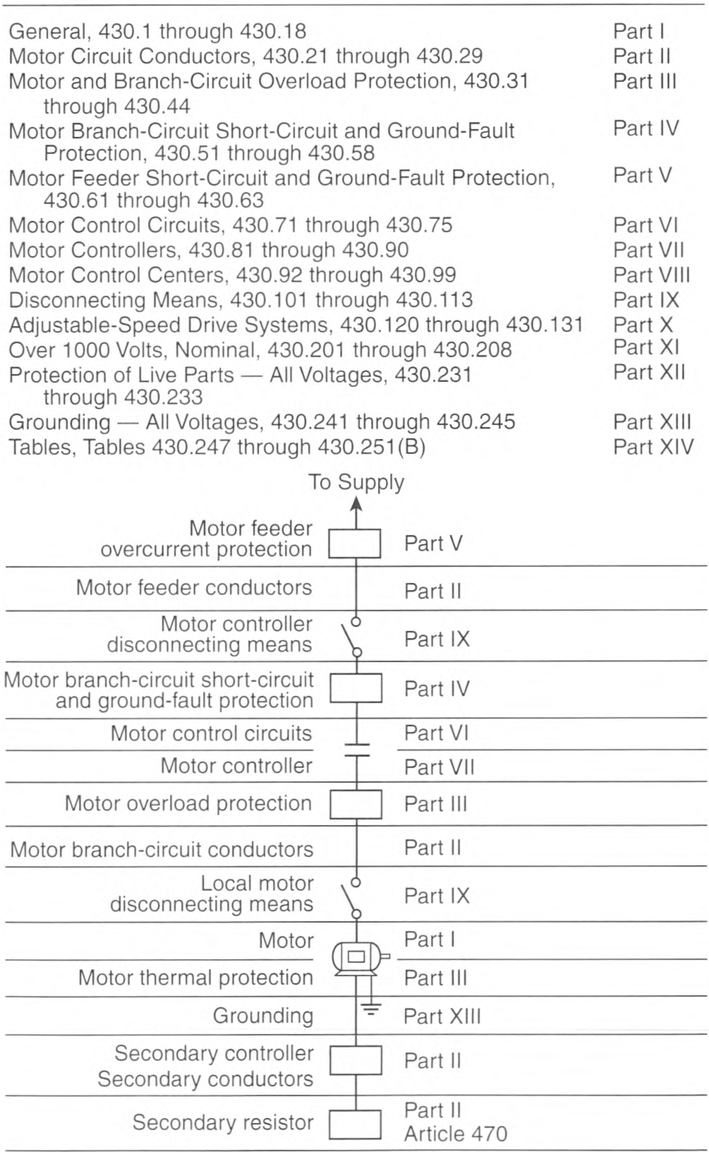
Informational Note Figure 430.1 Article 430 Contents..
Informational Note No. 1: See Informational Note Figure 430.1 for the arrangement of this article.
Informational Note No. 2: See 110.26(E) for installation requirements for motor control centers.
Informational Note No. 4: See Part X for additional requirements for motors utilizing adjustable-speed drive systems.
Informational Note No. 5: See Part XI for additional requirements for motors that operate over 1000 volts, nominal.
430.2 Reconditioned Motors.
Reconditioned motors shall be permitted if the reconditioning has been conducted in accordance with the manufacturer's instructions or, if no instructions are provided, nationally recognized standards.
Reconditioned motors identified for use in hazardous (classified) locations shall be listed as reconditioned if installed in hazardous (classified) locations.
Informational Note: See ANSI/EASA AR100-2020, Recommended Practice for the Repair of Rotating Electrical Apparatus, for information on the rewinding and repair of motors.
430.4 Part-Winding Motors.
Where separate overload devices are used with a standard part-winding start induction motor, each half of the motor winding shall be individually protected in accordance with 430.32 and 430.37 with a trip current one-half that specified.
Each motor-winding connection shall have branch-circuit short-circuit and ground-fault protection rated at not more than one-half that specified by 430.52.
Exception: A short-circuit and ground-fault protective device shall be permitted for both windings if the device will allow the motor to start. Where time-delay (dual-element) fuses are used, they shall be permitted to have a rating not exceeding 150 percent of the motor full-load current.
430.5 Other Articles.
Table 430.5 Other Articles.
| Equipment/Occupancy | Article | Section |
|---|---|---|
| Air-conditioning and refrigerating equipment | 440 | |
| Capacitors | 460.8, 460.9 | |
| Commercial garages; aircraft hangars; motor fuel dispensing facilities; bulk storage plants; spray application, dipping, and coating processes; and inhalation anesthetizing locations | 511, 513, 514, 515, 516, and 517 Part IV | |
| Cranes and hoists | 610 | |
| Electrically driven or controlled irrigation machines | 675 | |
| Elevators, dumbwaiters, escalators, moving walks, wheelchair lifts, and stairway chair lifts | 620 | |
| Fire pumps | 695 | |
| Hazardous (classified) locations | 500—503, 505, and 506 | |
| Industrial machinery | 670 | |
| Motion picture projectors | 540.11 and 540.20 | |
| Motion picture and television studios and similar locations | 530 | |
| Resistors and reactors | 470 | |
| Theaters, audience areas of motion picture and television studios, and similar locations | 520.48 | |
| Transformers and transformer vaults | 450 |
430.6 Conductor Ampacity and Motor Rating Determination.
The size of conductors supplying equipment covered by this article shall be selected from the ampacity tables in 310.15 or shall be calculated in accordance with 310.14(B). Where flexible cord is used, the size of the conductor shall be selected in accordance with 400.5. The required conductor ampacity and motor ratings shall be determined in accordance with 430.6(A), (B), (C), and (D).
(A) General Motor Applications.
For general motor applications, current ratings shall be determined based on 430.6(A)(1) and (A)(2).
(1) Table Values.
Other than for motors built for low speeds (less than 1200 RPM) or high torques, and for multispeed motors, the values given in Table 430.247, Table 430.248, Table 430.249, and Table 430.250 shall be used instead of the actual current rating marked on the motor nameplate to determine the following:
- Ampacity of conductors
- Current ratings of switches
- Current ratings of branch-circuit short-circuit and ground-fault protection
Where a motor is marked in amperes, but not horsepower, the horsepower rating shall be assumed to be that corresponding to the value given in Table 430.247, Table 430.248, Table 430.249, and Table 430.250, interpolated if necessary.
Exception No. 2: For equipment that employs a shaded-pole or permanent-split capacitor-type fan or blower motor that is marked with the motor type and the marking on the equipment nameplate is not less than the current marked on the fan or blower motor nameplate, the full-load current marked on the nameplate of the appliance shall be used to determine the ampacity of branch-circuit conductors in addition to the current ratings of the following:
- Disconnecting means
- Motor controllers
- Short-circuit and ground-fault protective devices
- Separate overload protective devices
Exception No. 3: For a listed motor-operated appliance that is marked with both motor horsepower and full-load current, the motor full-load current marked on the nameplate of the appliance shall be used instead of the horsepower rating on the appliance nameplate to determine the ampacity of branch-circuit conductors in addition to the current ratings of the following:
- Disconnecting means
- Motor controllers
- Short-circuit and ground-fault protective devices
- Separate overload protective devices
(2) Nameplate Values.
The motor nameplate current ratings shall be used to determine the values for the following:
- Separate motor overload protection
- For motors built for low speeds (less than 1200 RPM), high torques, canned pumps, or multispeed motors, the following:
- Ampacity of conductors
- Current ratings of switches
- Current ratings of branch-circuit short-circuit and ground-fault protection
- Large motors exceeding the values in Part XIV shall use the nameplate current rating for conductor sizing.
(B) Torque Motors.
For torque motors, the rated current shall be locked-rotor current, and this nameplate current shall be used to determine the ampacity of the branch-circuit conductors covered in 430.22 and 430.24, the current rating of the motor overload protection, and the current rating of motor branch-circuit short-circuit and ground-fault protection in accordance with 430.52(B).
Informational Note: See 430.83(D) and 430.110 for information on motor controllers and disconnecting means.
(C) Alternating-Current Adjustable Voltage Motors.
For motors used in alternating-current, adjustable voltage, variable torque drive systems, the ampacity of conductors, or current ratings of switches, branch-circuit short-circuit and ground-fault protection, and so forth, shall be based on the maximum operating current marked on the motor nameplate or the control nameplate, or both. If the maximum operating current does not appear on the nameplate, the current rating determination shall be based on 150 percent of the values given in Table 430.249 and Table 430.250.
(D) Valve Actuator Motor Assemblies.
For valve actuator motor assemblies (VAMs), the rated current shall be the name-plate full-load current, and this current shall be used to determine the maximum rating or setting of the motor branch-circuit short-circuit and ground-fault protective device and the ampacity of the conductors.
430.7 Marking on Motors and Multimotor Equipment.
(A) Usual Motor Applications.
A motor shall be marked with the following information:
- Manufacturer's name.
- Rated volts and full-load current. For a multispeed motor, full-load current for each speed, except shaded-pole and permanent-split capacitor motors where amperes are required only for maximum speed.
- Rated frequency and number of phases if an ac motor.
- Rated full-load speed.
- Rated temperature rise or the insulation system class and rated ambient temperature.
- Time rating. The time rating shall be 5, 15, 30, or 60 minutes, or continuous.
- Rated horsepower 1/8 hp or more. For a multispeed motor rated 1/8 hp or more, rated horsepower for each speed, except shaded-pole and permanent-split capacitor motors rated 1/8 hp or more where rated horsepower is required only for maximum speed. Motors of arc welders are not required to be marked with the horsepower rating.
- Code letter or locked-rotor amperes if an alternating-current motor rated 1/2 hp or more. On polyphase wound-rotor motors, the code letter shall be omitted.Informational Note No. 1: See 430.7(B).
- Design letter for design A, B, C, or D motors.Informational Note No. 2: See ANSI/NEMA MG 1-2016, Motors and Generators, Part 1, Definitions, for information on motor design letter definition.
- Secondary volts and full-load current if a wound-rotor induction motor.
- Field current and voltage for dc excited synchronous motors.
- Winding - straight shunt, stabilized shunt, compound, or series, if a dc motor. Fractional horsepower dc motors 175 mm (7 in.) or less in diameter shall not be required to be marked.
- A motor provided with a thermal protector complying with 430.32(A)(2) or (B)(2) shall be marked "thermally protected." Thermally protected motors rated 100 watts or less and complying with 430.32(B)(2) shall be permitted to use the abbreviated marking "T.P."
- A motor complying with 430.32(B)(4) shall be marked "impedance protected." Impedance-protected motors rated 100 watts or less and complying with 430.32(B)(4) shall be permitted to use the abbreviated marking "Z.P."
- Motors equipped with electrically powered condensation prevention heaters shall be marked with the rated heater voltage, number of phases, and the rated power in watts.
- Motors that are electronically protected from overloads in accordance with 430.32(A)(2) and (B)(2) shall be marked "electronically protected" or "E.P."
(B) Locked-Rotor Indicating Code Letters.
Code letters marked on motor nameplates to show motor input with locked rotor shall be in accordance with Table 430.7(B).
The code letter indicating motor input with locked rotor shall be in an individual block on the nameplate, properly designated.
Table 430.7(B) Locked-Rotor Indicating Code Letters.
| Code Letter | Kilovolt-Amperes per Horsepower with Locked Rotor |
|---|---|
| A | 0—3.14 |
| B | 3.15—3.54 |
| C | 3.55—3.99 |
| D | 4.0—4.49 |
| E | 4.5—4.99 |
| F | 5.0—5.59 |
| G | 5.6—6.29 |
| H | 6.3—7.09 |
| J | 7.1—7.99 |
| K | 8.0—8.99 |
| L | 9.0—9.99 |
| M | 10.0—11.19 |
| N | 11.2—12.49 |
| P | 12.5—13.99 |
| R | 14.0—15.99 |
| S | 16.0—17.99 |
| T | 18.0—19.99 |
| U | 20.0—22.39 |
| V | 22.4 and up |
(1) Multispeed Motors.
Multispeed motors shall be marked with the code letter designating the locked-rotor kilovolt-ampere (kVA) per horsepower (hp) for the highest speed at which the motor can be started.
Exception: Constant horsepower multispeed motors shall be marked with the code letter giving the highest locked-rotor kilovolt-ampere (kVA) per horsepower (hp).
(2) Single-Speed Motors.
Single-speed motors starting on wye connection and running on delta connections shall be marked with a code letter corresponding to the locked-rotor kilovolt-ampere (kVA) per horsepower (hp) for the wye connection.
(3) Dual-Voltage Motors.
Dual-voltage motors that have a different locked-rotor kilovolt-ampere (kVA) per horsepower (hp) on the two voltages shall be marked with the code letter for the voltage giving the highest locked-rotor kilovolt-ampere (kVA) per horsepower (hp).
(4) 50/60 Hz Motors.
Motors with 50- and 60-Hz ratings shall be marked with a code letter designating the locked-rotor kilovolt-ampere (kVA) per horsepower (hp) on 60 Hz.
(5) Part-Winding Motors.
Part-winding start motors shall be marked with a code letter designating the locked-rotor kilovolt-ampere (kVA) per horsepower (hp) that is based on the locked-rotor current for the full winding of the motor.
(C) Torque Motors.
Torque motors are rated for operation at standstill and shall be marked in accordance with 430.7(A), except that locked-rotor torque shall replace horsepower.
(D) Multimotor and Combination-Load Equipment.
(1) Factory-Wired.
Multimotor and combination-load equipment shall be provided with a visible nameplate marked with the manufacturer's name, the rating in volts, frequency, number of phases, minimum supply circuit conductor ampacity, and the maximum ampere rating of the circuit short-circuit and ground-fault protective device. The conductor ampacity shall be calculated in accordance with 430.24 and counting all of the motors and other loads that will be operated at the same time. The short-circuit and ground-fault protective device rating shall not exceed the value calculated in accordance with 430.53. Multimotor equipment for use on two or more circuits shall be marked with the preceding information for each circuit.
430.8 Marking on Motor Controllers.
A motor controller shall be marked with the manufacturer's name or identification, the voltage, the current or horsepower rating, the short-circuit current rating, and other necessary data to properly indicate the applications for which it is suitable.
Exception No. 1: The short-circuit current rating is not required for motor controllers applied in accordance with 430.81(A) or (B).
Exception No. 2: The short-circuit current rating is not required to be marked on the motor controller when the short-circuit current rating of the motor controller is marked elsewhere on the assembly.
Exception No. 3: The short-circuit current rating is not required to be marked on the motor controller when the assembly into which it is installed has a marked short-circuit current rating.
Exception No. 4: Short-circuit current ratings are not required for motor controllers rated less than 2 hp at 300 V or less and listed exclusively for general-purpose branch circuits.
A motor controller that includes motor overload protection suitable for group motor application shall be marked with the motor overload protection and the maximum branch-circuit short-circuit and ground-fault protection for such applications.
Combination motor controllers that employ adjustable instantaneous trip circuit breakers shall be clearly marked to indicate the ampere settings of the adjustable trip element.
Where a motor controller is built in as an integral part of a motor or of a motor-generator set, individual marking of the motor controller shall not be required if the necessary data are on the nameplate. For motor controllers that are an integral part of equipment approved as a unit, the above marking shall be permitted on the equipment nameplate.
Informational Note: See 110.10 for information on circuit impedance and other characteristics.
430.9 Terminals.
(A) Markings.
Terminals of motors and controllers shall be suitably marked or colored where necessary to indicate the proper connections.
(B) Conductors.
Motor controllers and terminals of control circuit devices shall be connected with copper conductors unless identified for use with a different conductor.
(C) Torque Requirements.
Control circuit devices with screw-type pressure terminals used with 14 AWG or smaller copper conductors shall be torqued to a minimum of 0.8 N-m (7 lb-in.) unless identified for a different torque value.
430.10 Wiring Space in Enclosures.
(A) General.
Enclosures for motor controllers and disconnecting means shall not be used as junction boxes, auxiliary gutters, or raceways for conductors feeding through or tapping off to the other apparatus unless designs are employed that provide adequate space for this purpose.
(B) Wire-Bending Space in Enclosures.
Minimum wire-bending space within the enclosures for motor controllers shall be in accordance with Table 430.10(B) where measured in a straight line from the end of the lug or wire connector (in the direction the wire leaves the terminal) to the wall or barrier. Where alternate wire termination means are substituted for that supplied by the manufacturer of the motor controller, they shall be of a type identified by the manufacturer for use with the motor controller and shall not reduce the minimum wire-bending space.
Table 430.10(B) Minimum Wire-Bending Space at the Terminals of Enclosed Motor Controllers.
| Size of Wire (AWG or kcmil) | Wires per Terminal* | |||
|---|---|---|---|---|
| 1 | 2 | |||
| mm | in. | mm | in. | |
| 10 and smaller | Not specified | - | - | |
| 8—6 | 38 | 11/2 | - | - |
| 4—3 | 50 | 2 | - | - |
| 2 | 65 | 21/2 | - | - |
| 1 | 75 | 3 | - | - |
| 1/0 | 125 | 5 | 125 | 5 |
| 2/0 | 150 | 6 | 150 | 6 |
| 3/0—4/0 | 175 | 7 | 175 | 7 |
| 250 | 200 | 8 | 200 | 8 |
| 300 | 250 | 10 | 250 | 10 |
| 350—500 | 300 | 12 | 300 | 12 |
| 600—700 | 350 | 14 | 400 | 16 |
| 750—900 | 450 | 18 | 475 | 19 |
430.11 Protection Against Liquids.
Suitable guards or enclosures shall be provided to protect exposed current-carrying parts of motors and the insulation of motor leads where installed directly under equipment, or in other locations where dripping or spraying oil, water, or other liquid is capable of occurring, unless the motor is designed for the existing conditions.
430.12 Motor Terminal Housings.
(A) Material.
Where motors are provided with terminal housings, the housings shall be of metal and of substantial construction.
(B) Dimensions and Space — Wire-to-Wire Connections.
Where these terminal housings enclose wire-to-wire connections, they shall have minimum dimensions and usable volumes in accordance with Table 430.12(B).
Table 430.12(B) Terminal Housings — Wire-to-Wire Connections.
| Motors 275 mm (11 in.) in Diameter or Less | ||||
|---|---|---|---|---|
| Horsepower | Cover Opening Minimum Dimension | Usable Volume Minimum | ||
| mm | in. | cm3 | in.3 | |
| 1 and smallera | 41 | 15/8 | 170 | 10.5 |
| 11/2, 2, and 3b | 45 | 13/4 | 275 | 16.8 |
| 5 and 71/2 | 50 | 2 | 365 | 22.4 |
| 10 and 15 | 65 | 21/2 | 595 | 36.4 |
Motors Over 275 mm (11 in.) in Diameter - Alternating-Current Motors.
| Maximum Full Load Current for 3-Phase Motors with Maximum of 12 Leads (Amperes) | Terminal Box Cover Opening Minimum Dimension | Usable Volume Minimum | Typical Maximum Horsepower 3-Phase | |||
|---|---|---|---|---|---|---|
| mm | in. | cm3 | in.3 | 230 Volt | 460 Volt | |
| 45 | 65 | 2.5 | 595 | 36.4 | 15 | 30 |
| 70 | 84 | 3.3 | 1,265 | 77 | 25 | 50 |
| 110 | 100 | 4.0 | 2,295 | 140 | 40 | 75 |
| 160 | 125 | 5.0 | 4,135 | 252 | 60 | 125 |
| 250 | 150 | 6.0 | 7,380 | 450 | 100 | 200 |
| 400 | 175 | 7.0 | 13,775 | 840 | 150 | 300 |
| 600 | 200 | 8.0 | 25,255 | 1540 | 250 | 500 |
Direct-Current Motors.
| Maximum Full-Load Current for Motors with Maximum of 6 Leads (Amperes) | Terminal Box Minimum Dimensions | Usable Volume Minimum | ||
|---|---|---|---|---|
| mm | in. | cm3 | in.3 | |
| 68 | 65 | 2.5 | 425 | 26 |
| 105 | 84 | 3.3 | 900 | 55 |
| 165 | 100 | 4.0 | 1,640 | 100 |
| 240 | 125 | 5.0 | 2,950 | 180 |
| 375 | 150 | 6.0 | 5,410 | 330 |
| 600 | 175 | 7.0 | 9,840 | 600 |
| 900 | 200 | 8.0 | 18,040 | 1,100 |
Note: Auxiliary leads for such items as brakes, thermostats, space heaters, and exciting fields shall be permitted to be neglected if their current-carrying area does not exceed 25 percent of the current-carrying area of the machine power leads.
(C) Dimensions and Space - Fixed Terminal Connections.
Where these terminal housings enclose rigidly mounted motor terminals, the terminal housing shall be of sufficient size to provide minimum terminal spacings and usable volumes in accordance with Table 430.12(C)(1) and Table 430.12(C)(2).
Table 430.12(C)(1) Terminal Spacings - Fixed Terminals.
| Nominal Volts | Minimum Spacing | |||
|---|---|---|---|---|
| Between Line Terminals | Between Line Terminals and Other Uninsulated Metal Parts | |||
| mm | in. | mm | in. | |
| 250 or less | 6 | 1/4 | 6 | 1/4 |
| Over 250 — 1000 | 10 | 3/8 | 10 | 3/8 |
Table 430.12(C)(2) Usable Volumes - Fixed Terminals.
| Power-Supply Conductor Size (AWG) | Minimum Usable Volume per Power-Supply Conductor | |
|---|---|---|
| cm3 | in.3 | |
| 14 | 16 | 1 |
| 12 and 10 | 20 | 11/4 |
| 8 and 6 | 37 | 21/4 |
(D) Large Wire or Factory Connections.
For motors with larger ratings, greater number of leads, or larger wire sizes, or where motors are installed as a part of factory-wired equipment, without additional connection being required at the motor terminal housing during equipment installation, the terminal housing shall be of ample size to make connections, but the foregoing provisions for the volumes of terminal housings shall not be considered applicable.
(E) Equipment Grounding Connections.
A means for attachment of an equipment grounding conductor termination in accordance with 250.8 shall be provided at motor terminal housings for wire-to-wire connections or fixed terminal connections. The means for such connections shall be permitted to be located either inside or outside the motor terminal housing.
Exception: Where a motor is installed as a part of factory-wired equipment that is required to be grounded and without additional connection being required at the motor terminal housing during equipment installation, a separate means for motor grounding at the motor terminal housing shall not be required.
430.13 Bushing.
Where wires pass through an opening in an enclosure, conduit box, or barrier, a bushing shall be used to protect the conductors from the edges of openings having sharp edges. The bushing shall have smooth, well-rounded surfaces where it may be in contact with the conductors. If used where oils, greases, or other contaminants may be present, the bushing shall be made of material not deleteriously affected.
Informational Note: See 310.10(F) for conductors exposed to deteriorating agents.
430.14 Location of Motors.
(A) Ventilation and Maintenance.
Motors shall be located so that adequate ventilation is provided and so that maintenance, such as lubrication of bearings and replacing of brushes, can be readily accomplished.
Exception: Ventilation shall not be required for submersible types of motors.
(B) Open Motors.
Open motors that have commutators or collector rings shall be located or protected so that sparks cannot reach adjacent combustible material.
Exception: Installation of these motors on wooden floors or supports shall be permitted.
430.16 Exposure to Dust Accumulations.
In locations where dust or flying material collects on or in motors in such quantities as to seriously interfere with the ventilation or cooling of motors and thereby cause dangerous temperatures, suitable types of enclosed motors that do not overheat under the prevailing conditions shall be used.
Informational Note: Especially severe conditions may require the use of enclosed pipe-ventilated motors, or enclosure in separate dusttight rooms, properly ventilated from a source of clean air.
430.21 General.
Part II specifies ampacities of conductors that are capable of carrying the motor current without overheating under the conditions specified.
Part II shall not apply to motor circuits rated over 1000 volts, nominal.
Informational Note No. 1: See Part XI for motor circuits rated over 1000 volts, nominal.
430.22 Single Motor.
Conductors that supply a single motor used in a continuous duty application shall have an ampacity of not less than 125 percent of the motor full-load current rating, as determined by 430.6(A)(1), or not less than specified in 430.22(A) through (G).
(A) Direct-Current Motor-Rectifier Supplied.
For dc motors operating from a rectified power supply, the conductor ampacity on the input of the rectifier shall not be less than 125 percent of the rated input current to the rectifier. For dc motors operating from a rectified single-phase power supply, the conductors between the field wiring output terminals of the rectifier and the motor shall have an ampacity of not less than the following percentages of the motor full-load current rating:
- Where a rectifier bridge of the single-phase, half-wave type is used, 190 percent.
- Where a rectifier bridge of the single-phase, full-wave type is used, 150 percent.
(B) Multispeed Motor.
For a multispeed motor, the selection of branch-circuit conductors on the line side of the controller shall be based on the highest of the full-load current ratings shown on the motor nameplate. The ampacity of the branch-circuit conductors between the controller and the motor shall not be less than 125 percent of the current rating of the winding(s) that the conductors energize.
(C) Wye-Start, Delta-Run Motor.
For a wye-start, delta-run connected motor, the ampacity of the branch-circuit conductors on the line side of the controller shall not be less than 125 percent of the motor full-load current as determined by 430.6(A)(1). The ampacity of the conductors between the controller and the motor shall not be less than 72 percent of the motor full-load current rating as determined by 430.6(A)(1).
Informational Note: The individual motor circuit conductors of a wye-start, delta-run connected motor carry 58 percent of the rated load current. The multiplier of 72 percent is obtained by multiplying 58 percent by 1.25.
(D) Part-Winding Motor.
For a part-winding connected motor, the ampacity of the branch-circuit conductors on the line side of the controller shall not be less than 125 percent of the motor full-load current as determined by 430.6(A)(1). The ampacity of the conductors between the controller and the motor shall not be less than 62.5 percent of the motor full-load current rating as determined by 430.6(A)(1).
Informational Note: The multiplier of 62.5 percent is obtained by multiplying 50 percent by 1.25.
(E) Other Than Continuous Duty.
Conductors for a motor used in a short-time, intermittent, periodic, or varying duty application shall have an ampacity of not less than the percentage of the motor nameplate current rating shown in Table 430.22(E), unless the authority having jurisdiction grants special permission for conductors of lower ampacity.
Table 430.22(E) Duty-Cycle Service.
| Classification of Service | Nameplate Current Rating Percentages | |||
|---|---|---|---|---|
| 5-Minute Rated Motor | 15-Minute Rated Motor | 30- & 60-Minute Rated Motor | Continuous Rated Motor | |
| Short-time duty operating valves, raising or lowering rolls, etc. | 110 | 120 | 150 | - |
| Intermittent duty freight and passenger elevators, tool heads, pumps, drawbridges, turntables, etc. (for arc welders, see 630.11) | 85 | 85 | 90 | 140 |
| Periodic duty rolls, ore- and coal-handling machines, etc. | 85 | 90 | 95 | 140 |
| Varying duty | 110 | 120 | 150 | 200 |
Note: Any motor application shall be considered as continuous duty unless the nature of the apparatus it drives is such that the motor will not operate continuously with load under any condition of use.
(F) Separate Terminal Enclosure.
The conductors between a stationary motor rated 1 hp or less and the separate terminal enclosure permitted in 430.245(B) shall be permitted to be smaller than 14 AWG but not smaller than 18 AWG, provided they have an ampacity as specified in 430.22.
(G) Conductors for Small Motors.
Conductors for small motors shall not be smaller than 14 AWG unless otherwise permitted in 430.22(G)(1) or (G)(2).
(1) 18 AWG Copper.
18 AWG individual copper conductors installed in a cabinet or enclosure, copper conductors that are part of a jacketed multiconductor cable assembly, or copper conductors in a flexible cord shall be permitted, under either of the following sets of conditions:
- The circuit supplies a motor with a full load current rating, as determined by 430.6(A)(1), of greater than 3.5 amperes, and less than or equal to 5 amperes, and all the following conditions are met:
- The circuit is protected in accordance with 430.52.
- The circuit is provided with maximum Class 10 or Class 10A overload protection in accordance with 430.32.
- Overcurrent protection is provided in accordance with 240.4(D)(1)(2).
- The circuit supplies a motor with a full-load current rating, as determined by 430.6(A)(1), of 3.5 amperes or less, and all the following conditions are met:
- The circuit is protected in accordance with 430.52.
- The circuit is provided with maximum Class 20 overload protection in accordance with 430.32.
- Overcurrent protection is provided in accordance with 240.4(D)(1)(2).
(2) 16 AWG Copper.
16 AWG individual copper conductors installed in a cabinet or enclosure, copper conductors that are part of a jacketed multiconductor cable assembly, or copper conductors in a flexible cord shall be permitted under either of the following sets of conditions:
- The circuit supplies a motor with a full-load current rating, as determined by 430.6(A)(1), of greater than 5.5 amperes, and less than or equal to 8 amperes, and all the following conditions are met:
- The circuit is protected in accordance with 430.52.
- The circuit is provided with maximum Class 10 or Class 10A overload protection in accordance with 430.32.
- Overcurrent protection is provided in accordance with 240.4(D)(2)(2).
- The circuit supplies a motor with a full-load current rating, as determined by 430.6(A)(1), of 5.5 amperes or less, and all the following conditions are met:
- The circuit is protected in accordance with 430.52.
- The circuit is provided with maximum Class 20 overload protection in accordance with 430.32.
- Overcurrent protection is provided in accordance with 240.4(D)(2)(2).
430.23 Wound-Rotor Secondary.
(A) Continuous Duty.
For continuous duty, the conductors connecting the secondary of a wound-rotor ac motor to its controller shall have an ampacity not less than 125 percent of the full-load secondary current of the motor.
(B) Other Than Continuous Duty.
For other than continuous duty, these conductors shall have an ampacity, in percent of full-load secondary current, not less than that specified in Table 430.22(E).
(C) Resistor Separate Front Controller.
Where the secondary resistor is separate from the controller, the ampacity of the conductors between controller and resistor shall not be less than that shown in Table 430.23(C).
430.24 Several Motors or a Motor(s) and Other Load(s).
Conductors supplying several motors, or a motor(s) and other load(s), shall have an ampacity not less than the sum of each of the following:
- 125 percent of the full-load current rating of the highest rated motor, as determined by 430.6(A)
- Sum of the full-load current ratings of all the other motors in the group, as determined by 430.6(A)
- 100 percent of the noncontinuous non-motor load
- 125 percent of the continuous non-motor load.
Informational Note: See Informative Annex D, Example No. D8.
Exception No. 1: Where one or more of the motors of the group are used for short-time, intermittent, periodic, or varying duty, the ampere rating of such motors to be used in the summation shall be determined in accordance with 430.22(E). For the highest rated motor, the greater of either the ampere rating from 430.22(E) or the largest continuous duty motor full-load current multiplied by 1.25 shall be used in the summation.
Exception No. 2: The ampacity of conductors supplying motor-operated fixed electric space-heating equipment shall comply with 424.4(B).
Exception No. 3: Where the circuitry is interlocked so as to prevent simultaneous operation of selected motors or other loads, the conductor ampacity shall be permitted to be based on the summation of the currents of the motors and other loads to be operated simultaneously that results in the highest total current.
430.25 Multimotor and Combination-Load Equipment.
The ampacity of the conductors supplying multimotor and combination-load equipment shall not be less than the minimum circuit ampacity marked on the equipment in accordance with 430.7(D). Where the equipment is not factory-wired and the individual nameplates are visible in accordance with 430.7(D)(2), the conductor ampacity shall be determined in accordance with 430.24.
430.26 Feeder Demand Factor.
Where reduced heating of the conductors results from motors operating on duty-cycle, intermittently, or from all motors not operating at one time, the authority having jurisdiction may grant permission for feeder conductors to have an ampacity less than specified in 430.24, provided the conductors have sufficient ampacity for the maximum load determined in accordance with the sizes and number of motors supplied and the character of their loads and duties.
Informational Note: Demand factors determined in the design of new facilities can often be validated against actual historical experience from similar installations.
430.28 Feeder Taps.
Feeder tap conductors shall have an ampacity not less than that required by Part II, shall terminate in a branch-circuit protective device, and, in addition, shall meet one of the following requirements:
- Be enclosed either by an enclosed controller or by a race-way, be not more than 3.0 m (10 ft) in length, and, for field installation, be protected by an overcurrent device on the line side of the tap conductor, the rating or setting of which shall not exceed 1000 percent of the tap conductor ampacity
- Have an ampacity of at least one-third that of the feeder conductors, be suitably protected from physical damage or enclosed in a raceway, and be not more than 7.5 m (25 ft) in length
- Have an ampacity not less than the feeder conductors
Exception: Feeder taps over 7.5 m (25 ft) long. In high-bay manufacturing buildings [over 11 m (35 ft) high at walls], where conditions of maintenance and supervision ensure that only qualified persons service the systems, conductors tapped to a feeder shall be permitted to be not over 7.5 m (25 ft) long horizontally and not over 30.0 m (100 ft) in total length where all of the following conditions are met:
- The ampacity of the tap conductors is not less than one-third that of the feeder conductors.
- The tap conductors terminate with a single circuit breaker or a single set of fuses complying with (1) Part IV, where the load-side conductors are a branch circuit, or (2) Part V, where the load-side conductors are a feeder.
- The tap conductors are suitably protected from physical damage and are installed in raceways.
- The tap conductors are continuous from end-to-end and contain no splices.
- The tap conductors shall be 6 AWG copper or 4 AWG aluminum or larger.
- The tap conductors shall not penetrate walls, floors, or ceilings.
- The tap shall not be made, less than 9.0 m (30 ft) from the floor.
430.29 Constant Voltage Direct-Current Motors - Power Resistors.
Conductors connecting the motor controller to separately mounted power accelerating and dynamic braking resistors in the armature circuit shall have an ampacity not less than the value calculated from Table 430.29 using motor full-load current. If an armature shunt resistor is used, the power accelerating resistor conductor ampacity shall be calculated using the total of motor full-load current and armature shunt resistor current.
Armature shunt resistor conductors shall have an ampacity of not less than that calculated from Table 430.29 using rated shunt resistor current as full-load current.
Table 430.29 Conductor Rating Factors for Power Resistors.
| Time in Seconds | Ampacity of Conductor in Percent of Full-Load Current | |
|---|---|---|
| On | Off | |
| 5 | 75 | 35 |
| 10 | 70 | 45 |
| 15 | 75 | 55 |
| 15 | 45 | 65 |
| 15 | 30 | 75 |
| 15 | 15 | 85 |
| Continuous Duty | 110 | |
430.31 General.
Part III specifies overload devices intended to protect motors, motor-control apparatus, and motor branch-circuit conductors against excessive heating due to motor overloads and failure to start.
Informational Note No. 1: See Informative Annex D, Example D8.
Informational Note No. 2: See Article 100 for the definition of Overload.
(B) Not Over 1000 Volts.
Part III shall not apply to motor circuits rated over 1000 volts, nominal.
Informational Note: See Part XI for over 1000 volts, nominal.
430.32 Continuous-Duty Motors.
(A) More Than 1 Horsepower.
Each motor used in a continuous duty application and rated more than 1 hp shall be protected against overload by one of the means in 430.32(A)(1) through (A)(4).
(1) Separate Overload Device.
A separate overload device that is responsive to motor current. This device shall be selected to trip or shall be rated at no more than the following percent of the motor nameplate full-load current rating:
| Motors with a marked service factor 1.15 or greater | 125% |
| Motors with a marked temperature rise 40°C or less | 125% |
| All other motors | 115% |
Modification of this value shall be permitted as provided in 430.32(C). For a multispeed motor, each winding connection shall be considered separately.
Where a separate motor overload device is connected so that it does not carry the total current designated on the motor nameplate, such as for wye-delta starting, the proper percentage of nameplate current applying to the selection or setting of the overload device shall be clearly designated on the equipment, or the manufacturer's selection table shall take this into account.
(2) Thermal Protector or Electronically Protected.
A thermal protector integral with the motor shall be approved for use with the motor it protects on the basis that it will prevent dangerous overheating of the motor due to overload and failure to start. An electronically protected motor shall be approved for use on the basis that it will prevent dangerous overheating due to the failure of the electronic control, overload, or failure to start the motor. The ultimate trip current of a thermally or electronically protected motor shall not exceed the following percentage of motor full-load current given in Table 430.248, Table 430.249, and Table 430.250:
| Motor full-load current 9 amperes or less | 170% |
| Motor full-load current from 9.1 to, and including, 20 amperes | 156% |
| Motor full-load current greater than 20 amperes | 140% |
If the motor current-interrupting device is separate from the motor and its control circuit is operated by a protective device integral with the motor, it shall be arranged so that the opening of the control circuit will result in interruption of current to the motor.
(4) Larger Than 1500 Horsepower.
For motors larger than 1500 hp, a protective device having embedded temperature detectors that cause current to the motor to be interrupted when the motor attains a temperature rise greater than marked on the nameplate in an ambient temperature of 40°C.
(B) One Horsepower or Less, Automatically Started.
Any motor of 1 hp or less that is started automatically shall be protected against overload by one of the following means.
(1) Separate Overload Device.
By a separate overload device following the requirements of 430.32(A)(1).
For a multispeed motor, each winding connection shall be considered separately. Modification of this value shall be permitted as provided in 430.32(C).
(2) Thermal Protector or Electronically Protected.
A thermal protector integral with the motor shall be approved for use with the motor that it protects on the basis that it will prevent dangerous overheating of the motor due to overload and failure to start. An electronically protected motor shall be approved for use on the basis that it will prevent dangerous overheating due to the failure of the electronic control, overload, or failure to start the motor. Where the motor current-interrupting device is separate from the motor and its control circuit is operated by a protective device integral with the motor, it shall be arranged so that the opening of the control circuit results in interruption of current to the motor.
(3) Integral With Motor.
A protective device integral with a motor that protects the motor against damage due to failure to start shall be permitted (1) if the motor is part of an approved assembly that does not subject the motor to overloads, or (2) if the assembly is also equipped with other safety controls (such as the safety combustion controls on a domestic oil burner) that protect the motor against damage due to failure to start. Where the assembly has safety controls that protect the motor, it shall be so indicated on the nameplate of the assembly where it will be visible after installation.
(4) Impedance-Protected.
If the impedance of the motor windings is sufficient to prevent overheating due to failure to start, the motor shall be permitted to be protected as specified in 430.32(D)(2)a. for manually started motors if the motor is part of an approved assembly in which the motor will limit itself so that it will not be dangerously overheated.
Informational Note: Many ac motors of less than 1/20 hp, such as clock motors, series motors, and so forth, and also some larger motors such as torque motors, come within this classification. It does not include split-phase motors having automatic switches that disconnect the starting windings.
(C) Selection of Overload Device.
Where the sensing element or setting or sizing of the overload device selected in accordance with 430.32(A)(1) and 430.32(B)(1) is not sufficient to start the motor or to carry the load, higher size sensing elements or incremental settings or sizing shall be permitted to be used, provided the trip current of the overload device does not exceed the following percentage of motor nameplate full-load current rating:
| Motors with marked service factor 1.15 or greater | 140% |
| Motors with a marked temperature rise 40°C or less | 140% |
| All other motors | 130% |
If not shunted during the starting period of the motor as provided in 430.35, the overload device shall have sufficient time delay to permit the motor to start and accelerate its load.
Informational Note: A Class 20 overload relay will provide a longer motor acceleration time than a Class 10 or Class 10A overload relay. A Class 30 overload relay will provide a longer motor acceleration time than a Class 20 overload relay. Use of a higher class overload relay may preclude the need for selection of a higher trip current.
(D) One Horsepower or Less, Nonautomatically Started.
(2) Not Permanently Installed.
- Within Sight from Controller. Overload protection shall be permitted to be furnished by the branch-circuit short-circuit and ground-fault protective device; such device, however, shall not be larger than that specified in Part IV of Article 430.Exception: Any such motor shall be permitted on a nominal 120-volt branch circuit protected at not over 20 amperes.
- Not Within Sight from Controller. Overload protection shall be in accordance with 430.32(B).
(E) Wound-Rotor Secondaries.
The secondary circuits of wound-rotor ac motors, including conductors, controllers, resistors, and so forth, shall be permitted to be protected against overload by the motor-overload device.
430.33 Intermittent and Similar Duty.
A motor used for a condition of service that is inherently short-time, intermittent, periodic, or varying duty, as illustrated by Table 430.22(E), shall be permitted to be protected against overload by the branch-circuit short-circuit and ground-fault protective device, provided the protective device rating or setting does not exceed that specified in Table 430.52(C)(1).
Any motor application shall be considered to be for continuous duty unless the nature of the apparatus it drives is such that the motor cannot operate continuously with load under any condition of use.
430.35 Shunting During Starting Period.
(A) Nonautomatically Started.
For a nonautomatically started motor, the overload protection shall be permitted to be shunted or cut out of the circuit during the starting period of the motor if the device by which the overload protection is shunted or cut out cannot be left in the starting position and if fuses or inverse time circuit breakers rated or set at not over 400 percent of the full-load current of the motor are located in the circuit so as to be operative during the starting period of the motor.
(B) Automatically Started.
The motor overload protection shall not be shunted or cut out during the starting period if the motor is automatically started.
Exception: The motor overload protection shall be permitted to be shunted or cut out during the starting period on an automatically started motor where the following apply:
(1) The motor starting period exceeds the time delay of available motor overload protective devices, and
(2) Listed means are provided to perform the following:
a. Sense motor rotation and automatically prevent the shunting or cutout in the event that the motor fails to start, and
b. Limit the time of overload protection shunting or cutout to less than the locked rotor time rating of the protected motor, and
c. Provide for shutdown and manual restart if motor running condition is not reached.
430.36 Fuses — In Which Conductor.
Where fuses are used for motor overload protection, a fuse shall be inserted in each ungrounded conductor and also in the grounded conductor if the supply system is 3-wire, 3-phase ac with one conductor grounded.
430.37 Devices Other Than Fuses — In Which Conductor.
Where devices other than fuses are used for motor overload protection, Table 430.37 shall govern the minimum allowable number and location of overload units such as trip coils or relays.
Table 430.37 Overload Units.
| Kind of Motor | Supply System | Number and Location of Overload Units, Such as Trip Coils or Relays |
|---|---|---|
| 1-phase ac or dc | 2-wire, 1-phase ac or dc ungrounded | 1 in either conductor |
| 1-phase ac or dc | 2-wire, 1-phase ac or dc, one conductor grounded | 1 in ungrounded conductor |
| 1-phase ac or dc | 3-wire, 1-phase ac or dc, grounded neutral conductor | 1 in either ungrounded conductor |
| 1-phase ac | Any 3-phase | 1 in ungrounded conductor |
| 2-phase ac | 3-wire, 2-phase ac, ungrounded | 2, one in each phase |
| 2-phase ac | 3-wire, 2-phase ac, one conductor grounded | 2 in ungrounded conductors |
| 2-phase ac | 4-wire, 2-phase ac, grounded or ungrounded | 2, one for each phase in ungrounded conductors |
| 2-phase ac | Grounded neutral or 5-wire, 2-phase ac, ungrounded | 2, one for each phase in any ungrounded phase wire |
| 3-phase ac | Any 3-phase | 3, one in each phase* |
430.38 Number of Conductors Opened by Overload Device.
Motor overload devices, other than fuses or thermal protectors, shall simultaneously open a sufficient number of ungrounded conductors to interrupt current flow to the motor.
430.39 Motor Controller as Overload Protection.
A motor controller shall also be permitted to serve as an overload device if the number of overload units complies with Table 430.37 and if these units are operative in both the starting and running position in the case of a dc motor, and in the running position in the case of an ac motor.
430.40 Overload Relays.
Overload relays and other devices for motor overload protection that are not capable of opening short circuits or ground faults shall be protected by fuses or circuit breakers with ratings or settings in accordance with 430.52 or by a motor short-circuit protector in accordance with 430.52.
Exception: Where approved for group installation and marked to indicate the maximum size of fuse or inverse time circuit breaker by which they must be protected, the overload devices shall be protected in accordance with this marking.
430.42 Motors on General-Purpose Branch Circuits.
Overload protection for motors used on general-purpose branch circuits shall be provided as specified in 430.42(A), (B), (C), or (D).
(A) Not Over 1 Horsepower.
One or more motors without individual overload protection shall be permitted to be connected to a general-purpose branch circuit only where the installation complies with the limiting conditions specified in 430.32(B), 430.32(D), and 430.53(A)(1) and (A)(2).
(B) Over 1 Horsepower.
Motors of ratings larger than specified in 430.53(A) shall be permitted to be connected to general-purpose branch circuits only where each motor is protected by overload protection selected to protect the motor as specified in 430.32. Both the motor controller and the motor overload device shall be approved for group installation with the short-circuit and ground-fault protective device selected in accordance with 430.53.
(C) Cord-and-Plug-Connected.
Where a motor is connected to a branch circuit by means of an attachment plug and a receptacle or cord connector, and individual overload protection is omitted in accordance with 430.42(A), the rating of the attachment plug and receptacle or cord connector shall not exceed 15 amperes at 125 volts or 250 volts. Where individual overload protection is required in accordance with 430.42(B) for a motor or motor-operated appliance that is attached to the branch circuit through an attachment plug and a receptacle or cord connector, the overload device shall be an integral part of the motor or appliance. The rating of the attachment plug and receptacle or cord connector shall determine the rating of the circuit to which the motor can be connected, in accordance with 210.21(B).
(D) Time Delay.
The branch-circuit short-circuit and ground-fault protective device protecting a circuit to which a motor or motor-operated appliance is connected shall have sufficient time delay to permit the motor to start and accelerate its load.
430.43 Automatic Restarting.
A motor overload device that can restart a motor automatically after overload tripping shall not be installed unless approved for use with the motor it protects. A motor overload device that can restart a motor automatically after overload tripping shall not be installed if automatic restarting of the motor can result in injury to persons.
430.44 Orderly Shutdown.
If immediate automatic shutdown of a motor by a motor overload protective device(s) would introduce additional or increased hazard(s) to a person(s) and continued motor operation is necessary for safe shutdown of equipment or process, a motor overload sensing device(s) complying with Part III of this article shall be permitted to be connected to a supervised alarm instead of causing immediate interruption of the motor circuit, so that corrective action or an orderly shutdown can be initiated.
430.51 General.
Part IV specifies devices intended to protect the motor branch-circuit conductors, the motor control apparatus, and the motors against overcurrent due to short circuits or ground faults. The devices specified in Part IV do not include the types of devices required by 210.8, 230.95, and 590.6.
Informational Note No. 1: See Informative Annex D, Example D8, for an example of motor branch-circuit short-circuit and ground-fault protection selection.
Part IV shall not apply to motor circuits rated over 1000 volts, nominal.
Informational Note No. 2: See Part XI for over 1000 volts, nominal.
430.52 Rating or Setting for Individual Motor Circuit.
(A) General.
The motor branch-circuit short-circuit and ground-fault protective device shall comply with 430.52(B) and either 430.52(C) or (D), as applicable.
(B) All Motors.
The motor branch-circuit short-circuit and ground-fault protective device shall be capable of carrying the starting current of the motor.
(C) Rating or Setting.
(1) In Accordance With Table 430.52(C)(1).
A protective device that has a rating or setting not exceeding the value calculated according to the values given in Table 430.52(C)(1) shall be used unless otherwise permitted in 430.52(C)(1)(a) or (C)(1)(b).
- Where the values as determined by Table 430.52(C)(1) do not correspond to the standard ampere ratings and settings provided in 240.6, the next higher standard rating or setting shall be permitted.
- Where the rating specified in Table 430.52(C)(1), or the rating modified by 430.52(C)(1) (a), is not sufficient for the starting current of the motor, any of the following shall apply:
- The rating of a nontime-delay fuse not exceeding 600 amperes or a time-delay Class CC fuse shall be permitted to be increased but shall in no case exceed 400 percent of the full-load current.
- The rating of a time-delay (dual-element) fuse shall be permitted to be increased but shall in no case exceed 225 percent of the full-load current.
- The rating of an inverse time circuit breaker shall be permitted to be increased but shall in no case exceed 400 percent for full-load currents of 100 amperes or less or 300 percent for full-load currents greater than 100 amperes.
- The rating of a fuse of 601-6000 ampere classification shall be permitted to be increased but shall in no case exceed 300 percent of the full-load current.
Informational Note: See Informative Annex D, Example D8, for an example of motor branch-circuit short-circuit and ground-fault rating and setting and Informational Note Figure 430.1 for an example location.
Table 430.52(C)(1) Maximum Rating or Setting of Motor Branch-Circuit Short-Circuit and Ground-Fault Protective Devices.
| Type of Motor | Percentage of Full-Load Current | |||
|---|---|---|---|---|
| Nontime Delay Fuse1 | Dual Element (Time-Delay) Fuse1 | Instantaneous-Trip Breaker | Inverse Time Breaker2 | |
| Single-phase motors | 300 | 175 | 800 | 250 |
| AC polyphase motors other than wound-rotor | 300 | 175 | 800 | 250 |
| Squirrel cage - other than Design B energy-efficient - and Design B premium efficiency | 300 | 175 | 800 | 250 |
| Design B energy-efficient and Design B premium efficiency | 300 | 175 | 1100 | 250 |
| Synchronous3 | 300 | 175 | 800 | 250 |
| Wound-rotor | 150 | 150 | 800 | 150 |
| DC (constant voltage) | 150 | 150 | 250 | 150 |
Note: See 430.54 for certain exceptions to the values specified.
2The values given in the last column also cover the ratings of nonadjustable inverse time types of circuit breakers that can be modified as in 430.52(C)(1)(a) and (C)(1)(b).
3Synchronous motors of the low-torque, low-speed type (usually 450 rpm or lower), such as those used to drive reciprocating compressors, pumps, and so forth, that start unloaded, do not require a fuse rating or circuit-breaker setting in excess of 200 percent of full-load current.
(2) Overload Relay Table.
Where maximum branch-circuit short-circuit and ground-fault protective device ratings are shown in the manufacturer's overload relay table for use with a motor controller or are otherwise marked on the equipment, they shall not be exceeded even if higher values are allowed as shown above.
(3) Instantaneous-Trip Circuit Breaker.
An instantaneous-trip circuit breaker shall be permitted if the conditions of 430.52(C)(3) (a) and (C)(3) (b) are met.
- Application. Instantaneous-trip circuit breakers shall be adjustable and part of a listed combination motor controller having coordinated motor overload and short-circuit and ground-fault protection in each conductor.Informational Note No. 1: Instantaneous-trip circuit breakers are also known as motor-circuit protectors (MCPs).Informational Note No. 2: For the purpose of this article, instantaneous-trip circuit breakers could include a damping means to accommodate a transient motor inrush current without nuisance tripping of the circuit breaker.
- Setting. The instantaneous-trip circuit breaker shall be adjusted to a setting in accordance with one of the following:
- No greater than the value specified in Table 430.52(C)(1)
- Where the value specified in Table 430.52(C)(1) is not sufficient for the starting current of the motor, one of the following settings shall be permitted:
- Motors other than design B energy-efficient and Design B premium efficiency motors shall be permitted to be increased but shall in no case exceed 1300 percent of the motor full-load current.
- Design B energy-efficient and Design B premium efficiency motors shall be permitted to be increased but shall in no case exceed 1700 percent of the motor full-load current.
- Where an engineering analysis determines the value is not sufficient for the starting current of the motor, it shall not be necessary to first apply the value specified in Table 430.52(C)(1).Informational Note No. 3: See NEMA MG 1-2016, Motors and Generators, Part 12.59 for additional information on the requirements for a motor to be classified "energy efficient."
- Where the motor full-load current is 8 amperes or less, the setting of the instantaneous-trip circuit breaker with a continuous current rating of 15 amperes or less in a listed combination motor controller that provides coordinated motor branch-circuit overload and short-circuit and ground-fault protection shall be permitted to be increased to the value marked on the motor controller.
(4) Multispeed Motor.
For a multispeed motor, a single short-circuit and ground-fault protective device shall be permitted for two or more windings of the motor if the rating of the protective device does not exceed the above applicable percentage of the nameplate rating of the smallest winding protected.
Exception: For a multispeed motor, a single short-circuit and ground-fault protective device shall be permitted to be used and sized according to the full-load current of the highest current winding, where all of the following conditions are met:
(1) Each winding is equipped with individual overload protection sized according to its full-load current.
(2) The branch-circuit conductors supplying each winding are sized according to the full-load current of the highest full-load current winding.
(3) The motor controller for each winding has a horsepower rating not less than that required for the winding having the highest horsepower rating.
(5) Power Electronic Devices.
Semiconductor fuses intended for the protection of electronic devices shall be permitted in lieu of devices listed in Table 430.52(C)(1) for power electronic devices, associated electromechanical devices (such as bypass contactors and isolation contactors), and conductors in a solid-state motor controller system if the marking for replacement fuses is provided adjacent to the fuses.
(6) Self-Protected Combination Motor Controller.
A listed self-protected combination motor controller shall be permitted in lieu of the devices specified in Table 430.52(C)(1). Adjustable instantaneous-trip settings shall not exceed 1300 percent of the full-load motor current for other than Design B energy-efficient and Design B premium efficiency motors and not more than 1700 percent of the full-load motor current for Design B energy-efficient and Design B premium efficiency motors.
Informational Note: Proper application of self-protected combination motor controllers on 3-phase systems, other than solidly grounded wye, particularly on corner grounded delta systems, considers the self-protected combination motor controllers' individual pole-interrupting capability.
(7) Motor Short-Circuit Protector.
A motor short-circuit protector shall be permitted in lieu of devices listed in Table 430.52(C)(1) if the motor short-circuit protector is part of a listed combination motor controller having coordinated motor overload protection and short-circuit and ground-fault protection in each conductor and it will open the circuit at currents exceeding 1300 percent of the motor full-load current for other than Design B energy-efficient and Design B premium efficiency motors and 1700 percent of the motor full-load current for Design B energy-efficient and Design B premium efficiency motors.
Informational Note: A motor short-circuit protector, as used in this section, is a fused device and is not an instantaneous-trip circuit breaker.
(D) Torque Motors.
Torque motor branch circuits shall be protected at the motor nameplate current rating in accordance with 240.4(B).
430.53 Several Motors or Loads on One Branch Circuit.
Two or more motors or one or more motors and other loads shall be permitted to be connected to the same branch circuit under conditions specified in 430.53(D) and in 430.53(A), (B), or (C). The branch-circuit protective device shall be fuses or inverse time circuit breakers.
(A) Not Over 1 Horsepower.
Several motors, each not exceeding 1 hp in rating, shall be permitted on a nominal 120-volt branch circuit protected at not over 20 amperes or a branch circuit of 1000 volts, nominal, or less, protected at not over 15 amperes, if all of the following conditions are met:
- The full-load rating of each motor does not exceed 6 amperes.
- The rating of the branch-circuit short-circuit and ground-fault protective device marked on any of the motor controllers is not exceeded.
- Individual overload protection conforms to 430.32.
(B) If Smallest Rated Motor Protected.
Two or more motors or one or more motors and other loads shall be permitted to be connected to a branch circuit where all of the following conditions are met:
- The branch-circuit short-circuit and ground-fault protective device is selected not to exceed that allowed by 430.52 for the smallest rated motor supplied by the branch circuit.
- Each motor is provided with separate overload protection.
- It can be determined that the branch-circuit short-circuit and ground-fault protective device will not open under the most severe normal conditions of service that might be encountered.
(C) Other Group Installations.
Two or more motors of any size or one or more motors and other loads, with each motor having individual overload protection, shall be permitted to be connected to a branch circuit where the motor controller(s) and overload device(s) comply with 430.53(C)(1) through (C)(5).
(1) Types of Assemblies.
The assembly type shall meet one of the following conditions:
- A listed factory assembly, with the motor branch-circuit short-circuit and ground-fault protective device either provided as part of the assembly or specified by a marking on the assembly
- Field installation of the motor branch-circuit short-circuit and ground-fault protective device, motor controller(s), and overload device(s) as separate assemblies listed for such use and provided with manufacturers' instructions for use with each other
(2) Motor Overload Devices.
Each motor overload device shall meet one of the following conditions:
- Listed for group installation with a specified maximum rating of fuse, inverse time circuit breaker, or both
- Selected such that the ampere rating of the motor-branch short-circuit and ground-fault protective device does not exceed that permitted by 430.52 for that individual motor overload device and corresponding motor load
(3) Motor Controllers.
Each motor controller shall meet one of the following conditions:
- Listed for group installation with a specified maximum rating of fuse, circuit breaker, or both
- Selected such that the ampere rating of the motor-branch short-circuit and ground-fault protective device does not exceed that permitted by 430.52 for that individual motor controller and corresponding motor load
(4) Short-Circuit & Ground-Fault Protection.
The branch circuit shall be protected by fuses or listed inverse time circuit breakers having a rating not exceeding the sum of all of the following:
- The value specified in 430.52 for the highest rated motor connected to the branch circuit
- The sum of the full-load current ratings of all other motors
- The sum of the current ratings of other loads connected to the circuit
Where this calculation results in a rating less than the ampacity of the branch-circuit conductors, it shall be permitted to increase the maximum rating of the fuses or circuit breaker to a value not exceeding that permitted by 240.4(B). Additionally, this rating shall not be larger than allowed by 430.40 for the overload relay protecting the smallest rated motor of the group.
(5) Overcurrent Protection.
Loads other than motor loads shall be protected in accordance with Part I through Part VII of Article 240.
Informational Note: See 110.10 for circuit impedance and other characteristics.
(D) Single Motor Taps.
For group installations described in 430.53(A), (B), or (C), the conductors of any tap supplying a single motor shall not be required to have an individual branch-circuit short-circuit and ground-fault protective device if they comply with 430.53(D)(1) or (D)(2).
(1) Conductors to the Motor.
Conductors to the motor shall have an ampacity that is not less than the ampacity of the branch-circuit conductors unless all of the following conditions are met:
- The conductors from the point of the tap to the motor overload device shall not be longer than 7.5 m (25 ft).
- The conductor ampacity is not less than one-third the ampacity of the branch-circuit conductors. The minimum ampacity shall not be less than required in 430.22.
- The conductors from the point of the tap to the motor controller(s) shall be protected from physical damage by being enclosed in an approved raceway or other approved means.
(2) Tap Conductors Between the Branch Circuit and Listed Manual Motor Controllers.
Conductors from the point of the tap from the branch circuit to a listed manual motor controller additionally marked "Suitable for Tap Conductor Protection in Group Installations," or to a branch-circuit protective device, shall meet one of the following conditions:
- The length of the motor tap conductors does not exceed 3 m (10 ft) and the tap conductors comply with all of the following:
- The ampacity of the tap conductors is not less than one-tenth of the rating or setting of the branch-circuit short-circuit ground-fault protective device.
- The conductors from the motor controller to the motor shall have an ampacity in accordance with 430.22.
- The conductors from the point of the tap to the motor controller(s) shall be suitably protected from physical damage and enclosed either by an enclosed motor controller or by a raceway.Exception to (1): Physical protection of the conductors from the point of the lap to the motor controllers shall not be required if the conductors have an ampacity not less than that of the branch-circuit conductors.
- The length of the motor tap conductors does not exceed 7.5 m (25 ft) and the tap conductors comply with all of the following:
- The ampacity of the tap conductors is not less than one-third of the branch-circuit conductor ampacity.
- The conductors from the motor controller to the motor shall have an ampacity in accordance with 430.22.
- The conductors from the point of the tap to the motor controller(s) shall be suitably protected from physical damage and enclosed either by an enclosed motor controller or by a raceway.
Exception to (2): Physical protection of the conductors from the point of the tap to the motor controllers shall not be required if the conductors have an ampacity not less than that of the branch-circuit conductors.
430.54 Multimotor and Combination-Load Equipment.
The rating of the branch-circuit short-circuit and ground-fault protective device for multimotor and combination-load equipment shall not exceed the rating marked on the equipment in accordance with 430.7(D).
430.55 Combined Overcurrent Protection.
Motor branch-circuit short-circuit and ground-fault protection and motor overload protection shall be permitted to be combined in a single protective device where the rating or setting of the device provides the overload protection specified in 430.32.
430.57 Size of Fuseholder.
Where fuses are used for motor branch-circuit short-circuit and ground-fault protection, the fuseholders shall not be of a smaller size than required to accommodate the fuses specified by Table 430.52(C)(1).
430.58 Rating of Circuit Breaker.
A circuit breaker for motor branch-circuit short-circuit and ground-fault protection shall have a current rating in accordance with 430.52 and 430.110.
430.61 General.
Part V specifies protective devices intended to protect feeder conductors supplying motors against overcurrents due to short circuits or ground-faults.
Informational Note: See Informative Annex D, Example D8, for an example of motor feeder circuit short-circuit and ground-fault protection rating and setting.
430.62 Rating or Setting — Motor Load.
(A) Specific Load.
A feeder supplying a specific fixed motor load(s) and consisting of conductor sizes in accordance with 430.24 shall be provided with a protective device having a rating or setting not greater than the largest rating or setting of the branch-circuit short-circuit and ground-fault protective device for any motor supplied by the feeder [based on the maximum permitted value for the specific type of protective device in accordance with 430.52, or 440.22(A) for hermetic refrigerant motor-compressors], plus the sum of the full-load currents of the other motors of the group.
Where the same rating or setting of the branch-circuit short-circuit and ground-fault protective device is used on two or more of the branch circuits supplied by the feeder, one of the protective devices shall be considered the largest for the above calculations.
Exception No. 1: Where one or more instantaneous-trip circuit breakers or motor short-circuit protectors are used for motor branch-circuit short-circuit and ground-fault protection as permitted in 430.52(C), the maximum rating of each instantaneous-trip circuit breaker or motor short-circuit protector shall be assumed to have a rating not exceeding the maximum percentage of motor full-load current permitted by Table 430.52(C)(1) for the type of feeder protective device employed.
Exception No. 2: Where the feeder overcurrent protective device also provides overcurrent protection for a motor control center, the provisions of 430.94 shall apply.
Informational Note: See Informative Annex D, Example D8, for an example of motor feeder circuit short-circuit and ground-fault protection rating and setting.
430.63 Rating or Setting - Motor Load and Other Load(s).
Where a feeder supplies a motor load and other load(s), the feeder protective device shall have a rating not less than that required for the sum of the other load(s) plus the following:
- For a single motor, the rating permitted by 430.52
- For a single hermetic refrigerant motor-compressor, the rating permitted by 440.22
- For two or more motors, the rating permitted by 430.62
Exception: Where the feeder overcurrent device provides the overcurrent protection for a motor control center, the provisions of 430.94 shall apply.
430.71 General.
Part VI contains modifications of the general requirements and applies to the particular conditions of motor control circuits.
430.72 Overcurrent Protection.
(A) General.
A motor control circuit tapped from the load side of a motor branch-circuit short-circuit and ground-fault protective device(s) and functioning to control the motor(s) connected to that branch circuit shall be protected against overcurrent in accordance with 430.72. Such a tapped control circuit shall not be considered to be a branch circuit and shall be permitted to be protected by either a supplementary or branch-circuit overcurrent protective device(s). A motor control circuit other than such a tapped control circuit shall be protected against overcurrent in accordance with 724.43 or the notes to Table 11 (A) and Table 11 (B) in Chapter 9, as applicable.
(B) Conductor Protection.
The overcurrent protection for conductors shall be provided as specified in 430.72(B)(1) or (B)(2).
Exception No. 1: Where the opening of the control circuit would create a hazard as, for example, the control circuit of a fire pump motor, and the like, conductors of control circuits shall require only short-circuit and ground-fault protection and shall be permitted to be protected by the motor branch-circuit short-circuit and ground-fault protective device(s).
Exception No. 2: Conductors supplied by the secondary side of a single-phase transformer having only a two-wire (single-voltage) secondary shall be permitted to be protected by overcurrent protection provided on the primary (supply) side of the transformer, provided this protection does not exceed the value determined by multiplying the appropriate maximum rating of the overcurrent device for the secondary conductor from Table 430.72(B)(2) by the secondary-to-primary voltage ratio. Transformer secondary conductors (other than two-wire) shall not be considered to be protected by the primary overcurrent protection.
(1) Separate Overcurrent Protection.
Where the motor branch-circuit short-circuit and ground-fault protective device does not provide protection in accordance with 430.72(B)(2), separate overcurrent protection shall be provided. The over-current protection shall not exceed the values specified in Column A of Table 430.72(B)(2).
(2) Branch-Circuit Overcurrent Protective Device.
Conductors shall be permitted to be protected by the motor branch-circuit short-circuit and ground-fault protective device and shall require only short-circuit and ground-fault protection. Where the conductors do not extend beyond the motor control equipment enclosure, the rating of the protective device(s) shall not exceed the value specified in Column B of Table 430.72(B)(2). Where the conductors extend beyond the motor control equipment enclosure, the rating of the protective device(s) shall not exceed the value specified in Column C of Table 430.72(B)(2).
Table 430.72(B)(2) Maximum Rating of Overcurrent Protective Device in Amperes.
| Control Circuit Conductor Size (AWG) | Column A Separate Protection Provided |
Protection Provided by Motor Branch-Circuit Protective Device(s) | ||||
|---|---|---|---|---|---|---|
| Column B Conductors Within Enclosure |
Column C Conductors Extend Beyond Enclosure |
|||||
| Copper | Aluminum or Copper-Clad Aluminum | Copper | Aluminum or Copper-Clad Aluminum | Copper | Aluminum or Copper-Clad Aluminum | |
| 18 | 7 | - | 25 | - | 7 | - |
| 16 | 10 | - | 40 | - | 10 | - |
| 14 | (Note 1) | - | 100 | - | 45 | - |
| 12 | (Note 1) | (Note 1) | 120 | 100 | 60 | 45 |
| 10 | (Note 1) | (Note 1) | 160 | 140 | 90 | 75 |
| Larger than 10 | (Note 1) | (Note 1) | (Note 2) | (Note 2) | (Note 3) | (Note 3) |
Notes:
- Value specified in 310.15 as applicable.
- 400 percent of value specified in Table 310.17 for 60°C conductors.
- 300 percent of value specified in Table 310.16 for 60°C conductors.
(C) Control Circuit Transformer.
Where a motor control circuit transformer is provided, the transformer shall be protected in accordance with 430.72(C)(1), (C)(2), (C)(3), (C)(4), or (C)(5).
Exception: Overcurrent protection shall be omitted where the opening of the control circuit would create a hazard as, for example, the control circuit of a fire pump motor and the like.
(1) Class 1 Power-Limited, Class 2, or Class 3 Circuits.
Where the transformer supplies a Class 1 power-limited circuit, the circuit shall comply with 724.30 through 724.52. Where the transformer supplies a Class 2 or Class 3 remote-control circuit, the circuit shall comply with the requirements of Part II of Article 725.
(3) Less Than 50 Volt-Amperes.
Control circuit transformers rated less than 50 volt-amperes (VA) and that are an integral part of the motor controller and located within the motor controller enclosure shall be permitted to be protected by primary overcurrent devices, impedance limiting means, or other inherent protective means.
(4) Primary Less Than 2 Amperes.
Where the control circuit transformer rated primary current is less than 2 amperes, an overcurrent device rated or set at not more than 500 percent of the rated primary current shall be permitted in the primary circuit.
430.73 Protection of Conductors From Physical Damage.
Where damage to a motor control circuit would constitute a hazard, all conductors of such a remote motor control circuit that are outside the control device itself shall be installed in a raceway or be otherwise protected from physical damage.
430.74 Electrical Arrangement of Control Circuits.
Where one conductor of the motor control circuit is grounded, the motor control circuit shall be arranged so that a ground fault in the control circuit remote from the motor controller will (1) not start the motor and (2) not bypass manually operated shutdown devices or automatic safety shutdown devices.
430.75 Disconnection.
(A) General.
Motor control circuits shall be arranged so that they will be disconnected from all sources of supply when the disconnecting means is in the open position. The disconnecting means shall be permitted to consist of two or more separate devices, one of which disconnects the motor and the motor controller from the source(s) of power supply for the motor, and the other(s), the motor control circuit(s) from its power supply. Where separate devices are used, they shall be located immediately adjacent to each other.
Exception No. 1: Where more than 12 motor control circuit conductors are required to be disconnected, the disconnecting means shall be permitted to be located other than immediately adjacent to each other where all of the following conditions are met:
- Access to energized parts is limited to qualified persons in accordance with Part XII of this article.
- A warning sign is permanently located on the outside of each equipment enclosure door or cover permitting access to the live parts in the motor control circuit(s), warning that motor control circuit disconnecting means are remotely located and specifying the location and identification of each disconnect. Where energized parts are not in an equipment enclosure as permitted by 430.232 and 430.233, an additional warning sign(s) shall be located where visible to persons who may be working in the area of the energized parts.
Exception No. 2: The motor control circuit disconnecting means shall be permitted to be remote from the motor controller power supply disconnecting means where the opening of one or more motor control circuit disconnecting means is capable of resulting in potentially unsafe conditions for personnel or property and the conditions of items (1) and (2) of Exception No. 1 are met.
(B) Control Transformer in Motor Controller Enclosure.
Where a transformer or other device is used to obtain a reduced voltage for the motor control circuit and is located in the motor controller enclosure, such transformer or other device shall be connected to the load side of the disconnecting means for the motor control circuit.
430.81 General.
(A) Stationary Motor of 1/8 Horsepower or Less.
For a stationary motor rated at 1/8 hp or less that is normally left running and is constructed so that it cannot be damaged by overload or failure to start, such as clock motors and the like, the branch-circuit disconnecting means shall be permitted to serve as the motor controller.
(B) Portable Motor of 1/3 Horsepower or Less.
For a portable motor rated at 1/3 hp or less, the motor controller shall be permitted to be an attachment plug and receptacle or cord connector.
430.82 Motor Controller Design.
(A) Starting and Stopping.
Each motor controller shall be capable of starting and stopping the motor it controls and shall be capable of interrupting the locked-rotor current of the motor.
(C) Rheostats.
Rheostats shall be in compliance with the following:
- Motor-starting rheostats shall be designed so that the contact arm cannot be left on intermediate segments. The point or plate on which the arm rests when in the starting position shall have no electrical connection with the resistor.
- Motor-starting rheostats for dc motors operated from a constant voltage supply shall be equipped with automatic devices that will interrupt the supply before the speed of the motor has fallen to less than one-third its normal rate.
430.83 Ratings.
The motor controller shall have a rating in accordance with 430.83(A), unless otherwise permitted in 430.83(B) or (C), or in accordance with (D), under the conditions specified.
(A) General.
(1) Horsepower Ratings.
Motor controllers, other than inverse time circuit breakers and molded case switches, shall have horsepower ratings at the application voltage not lower than the horsepower rating of the motor.
(2) Circuit Breaker.
A branch-circuit inverse time circuit breaker rated in amperes shall be permitted as a motor controller for all motors. Where this circuit breaker is also used for overload protection, it shall conform to the appropriate provisions of this article governing overload protection.
(C) Stationary Motors of 2 Horsepower or Less.
For stationary motors rated at 2 hp or less and 300 volts or less, the motor controller shall be permitted to be either of the following:
- A general-use switch having an ampere rating not less than twice the full-load current rating of the motor
- On ac circuits, a general-use snap switch suitable only for use on ac (not general-use ac—dc snap switches) where the motor full-load current rating is not more than 80 percent of the ampere rating of the switch
(D) Torque Motors.
For torque motors, the motor controller shall have a continuous-duty, full-load current rating not less than the nameplate current rating of the motor. For a motor controller rated in horsepower but not marked with the foregoing current rating, the equivalent current rating shall be determined from the horsepower rating by using Table 430.247, Table 430.248, Table 430.249, or Table 430.250.
(E) Voltage Rating.
A motor controller with a straight voltage rating, for example, 240 volts or 480 volts, shall be permitted to be applied in a circuit in which the nominal voltage between any two conductors does not exceed the motor controller's voltage rating. A motor controller with a slash rating, for example, 120/240 volts or 480Y/277 volts, shall only be applied in a solidly grounded circuit in which the nominal voltage to ground from any conductor does not exceed the lower of the two values of the motor controller's voltage rating and the nominal voltage between any two conductors does not exceed the higher value of the motor controller's voltage rating.
(F) Short-Circuit Current Rating.
A motor controller shall not be installed where the available fault current exceeds the motor controller's short-circuit current rating.
Informational Note: The short-circuit current rating might be marked on the device or might be a rating for a tested combination specified in the motor controller's technical manual or instruction sheet.
430.84 Need Not Open All Conductors.
The motor controller shall not be required to open all conductors to the motor.
Exception: Where the motor controller serves also as a disconnecting means, it shall open all ungrounded conductors to the motor in accordance with 430.111.
430.85 In Grounded Conductors.
One pole of the motor controller shall be permitted to be placed in a permanently grounded conductor if the motor controller is designed so that the pole in the grounded conductor cannot be opened without simultaneously opening all conductors of the circuit.
430.87 Number of Motors Served by Each Motor Controller.
Each motor shall be provided with an individual motor controller.
Exception No. 1: For motors rated 1000 volts or less, a single motor controller rated at not less than the equivalent horsepower, as determined in accordance with 430.110(C)(1), of all the motors in the group shall be permitted to serve the group under any of the following conditions:
(1) Where a number of motors drive several parts of a single machine, or piece of apparatus, such as metal and woodworking machines, cranes, hoists, and similar apparatus
(2) Where a group of motors is under the protection of one overcurrent device in accordance with 430.53(A)
(3) Where a group of motors is located in a single room within sight from the motor controller location
Exception No. 2: A branch-circuit disconnecting means serving as the motor controller in accordance with 430.81(A) shall be permitted to serve more than one motor.
430.88 Adjustable-Speed Motors.
Adjustable-speed motors that are controlled by means of field regulation shall be equipped and connected so that they cannot be started under a weakened field.
Exception: Starting under a weakened field shall be permitted where the motor is designed for such starting.
430.89 Speed Limitation.
Machines of the following types shall be provided with speed-limiting devices or other speed-limiting means:
- Separately excited dc motors
- Series motors
- Motor-generators and converters that can be driven at excessive speed from the dc end, as by a reversal of current or decrease in load
Exception: Separate speed-limiting devices or means shall not be required under either of the following conditions:
430.90 Combination Fuseholder and Switch as Motor Controller.
The rating of a combination fuseholder and switch used as a motor controller shall be such that the fuseholder will accommodate the size of the fuse specified in Part III of this article for motor overload protection.
Exception: Where fuses having time delay appropriate for the starting characteristics of the motor are used, fuseholders of smaller size than specified in Part III of this article shall be permitted.
430.92 General.
Part VIII covers motor control centers installed for the control of motors, lighting, and power circuits.
430.94 Overcurrent Protection.
Motor control centers shall be provided with overcurrent protection in accordance with Parts I, II, and VIII of Article 240. The ampere rating or setting of the overcurrent protective device shall not exceed the rating of the common power bus. This protection shall be provided by (1) an overcurrent protective device located ahead of the motor control center or (2) a main overcurrent protective device located within the motor control center.
430.95 Service Equipment.
Where used as service equipment, each motor control center shall be provided with a single main disconnecting means to disconnect all ungrounded service conductors.
Where a grounded conductor is provided, the motor control center shall be provided with a main bonding jumper, sized in accordance with 250.28(D), within one of the sections for connecting the grounded conductor, on its supply side, to the motor control center equipment ground bus.
430.96 Grounding.
Multisection motor control centers shall be connected together with an equipment grounding conductor or an equivalent equipment grounding bus sized in accordance with Table 250.122. Equipment grounding conductors shall be connected to this equipment grounding bus or to a grounding termination point provided in a single-section motor control center.
430.97 Busbars and Conductors.
(A) Support and Arrangement.
Busbars shall be protected from physical damage and be held firmly in place. Other than for required interconnections and control wiring, only those conductors that are intended for termination in a vertical section shall be located in that section.
Exception: Conductors shall be permitted to travel horizontally through vertical sections where such conductors are isolated from the busbars by a barrier.
(B) Phase Arrangement.
The phase arrangement on 3-phase horizontal common power and vertical buses shall be A, B, C from front to back, top to bottom, or left to right, as viewed from the front of the motor control center. The B phase shall be that phase having the higher voltage to ground on 3-phase, 4-wire, delta-connected systems. Other busbar arrangements shall be permitted for additions to existing installations and shall be marked.
Exception: Rear-mounted units connected to a vertical bus that is common to front-mounted units shall be permitted to have a C, B, A phase arrangement where properly identified.
(C) Minimum Wire-Bending Space.
The minimum wire-bending space at the motor control center terminals and minimum gutter space shall be in accordance with 312.6.
(D) Spacings.
Spacings between motor control center bus terminals and other bare metal parts shall not be less than specified in Table 430.97(D).
Table 430.97(D) Minimum Spacing Between Bare Metal Parts.
| Nominal Voltage | Opposite Polarity Where Mounted on the Same Surface | Opposite Polarity Where Held Free in Air | Live Parts to Ground | |||
|---|---|---|---|---|---|---|
| mm | in. | mm | in. | mm | in. | |
| Not over 125 volts, nominal | 19.1 | 3/4 | 12.7 | 1/2 | 12.7 | 1/2 |
| Not over 250 volts, nominal | 31.8 | 11/4 | 19.1 | 3/4 | 12.7 | 1/2 |
| Not over 600 volts, nominal | 50.8 | 2 | 25.4 | 1 | 25.4 | 1 |
(E) Barriers.
Barriers shall be placed in all service-entrance motor control centers to isolate service busbars and terminals from the remainder of the motor control center.
430.98 Marking.
(A) Motor Control Centers.
Motor control centers shall be marked according to 110.21, and the marking shall be plainly visible after installation. Marking shall also include common power bus current rating and motor control center short-circuit current rating.
430.99 Available Fault Current.
The available fault current at the motor control center and the date the available fault current calculation was performed shall be documented and made available to those authorized to inspect, install, or maintain the installation.
430.101 General.
Part IX is intended to require disconnecting means capable of disconnecting motors and motor controllers from the circuit.
430.102 Location.
(A) Motor Controller.
An individual disconnecting means shall be provided for each motor controller and shall disconnect the motor controller. The disconnecting means shall be located in sight from the motor controller location.
Exception No. 1: For motor circuits over 1000 volts, nominal, a motor controller disconnecting means lockable in accordance with 110.25 shall be permitted to be out of sight of the motor controller if the motor controller is marked with a label giving the location of the disconnecting means.
Exception No. 2: A single disconnecting means shall be permitted for a group of coordinated motor controllers that drive several parts of a single machine or piece of apparatus. The disconnecting means shall be located in sight from the motor controllers, and both the disconnecting means and the motor controllers shall be located in sight from the machine or apparatus.
Exception No. 3: The disconnecting means shall not be required to be in sight from valve actuator motor (VAM) assemblies containing the motor controller where such a location introduces additional or increased hazards to persons or property and the following conditions are met:
(1) The valve actuator motor assembly is marked with a label giving the location of the disconnecting means.
(2) The disconnecting means is lockable in accordance with 110.25.
(B) Motor.
(1) Separate Motor Disconnect.
A disconnecting means for the motor shall be located in sight from the motor location and the driven machinery location.
(2) Motor Controller Disconnect.
The motor controller disconnecting means required in accordance with 430.102(A) shall be permitted to serve as the disconnecting means for the motor if it is in sight from the motor location and the driven machinery location.
Exception to (1) and (2): The disconnecting means for the motor shall not be required under either of the following conditions if the motor controller disconnecting means required in 430.102(A) is lockable in accordance with 110.25:
(1) Where such a location of the disconnecting means for the motor is impracticable or introduces additional or increased hazards to persons or property
Informational Note No. 1: Some examples of increased or additional hazards include, but are not limited to, motors rated in excess of 100 hp, multimotor equipment, submersible motors, motors associated with adjustable-speed drives, and motors located in hazardous (classified) locations.
(2) In industrial installations, with written safety procedures, where conditions of maintenance and supervision ensure that only qualified persons service the equipment
Informational Note No. 2: See NFPA 70E-2021, Standard for Electrical Safety in the Workplace, for information on lockout/tagout procedures.
430.103 Operation.
The disconnecting means shall open all ungrounded supply conductors and shall be designed so that no pole can be operated independently. The disconnecting means shall be permitted in the same enclosure with the motor controller. The disconnecting means shall be designed so that it cannot be closed automatically.
430.104 To Be Indicating.
The disconnecting means shall plainly indicate whether it is in the open (off) or closed (on) position.
430.105 Grounded Conductors.
One pole of the disconnecting means shall be permitted to disconnect a permanently grounded conductor, provided the disconnecting means is designed so that the pole in the grounded conductor cannot be opened without simultaneously disconnecting all conductors of the circuit.
430.108 Every Disconnecting Means.
Every disconnecting means in the motor circuit between the point of attachment to the feeder or branch circuit and the point of connection to the motor shall comply with the requirements of 430.109 and 430.110.
430.109 Type.
The disconnecting means shall be a type in accordance with 430.109(A), unless otherwise permitted in 430.109(B) through (G), under the conditions specified.
(A) General.
(3) Molded Case Switch.
A listed molded case switch.
(6) Manual Motor Controller.
Listed manual motor controllers additionally marked "Suitable as Motor Disconnect" shall be permitted as a disconnecting means where installed between the final motor branch-circuit short-circuit protective device and the motor. Listed manual motor controllers additionally marked "Suitable as Motor Disconnect" shall be permitted as disconnecting means on the line side of the fuses in accordance with 430.52(C)(5). In this case, the fuses permitted in 430.52(C)(5) shall be considered supplementary fuses, and suitable branch-circuit short-circuit and ground-fault protective devices shall be installed on the line side of the manual motor controller additionally marked "Suitable as Motor Disconnect."
(7) System Isolation Equipment.
System isolation equipment shall be listed for disconnection purposes. System isolation equipment shall be installed on the load side of the overcurrent protection and its disconnecting means. The disconnecting means shall be one of the types permitted by 430.109(A)(1) through (A)(3).
(B) Stationary Motors of 1/8 Horsepower or Less.
For stationary motors of 1/8 hp or less, the branch-circuit overcurrent device shall be permitted to serve as the disconnecting means.
(C) Stationary Motors of 2 Horsepower or Less.
For stationary motors rated at 2 hp or less and 300 volts or less, the disconnecting means shall be permitted to be one of the following devices:
- A general-use switch having an ampere rating not less than twice the full-load current rating of the motor
- On ac circuits, a general-use snap switch suitable only for use on ac (not general-use ac—dc snap switches) where the motor full-load current rating is not more than 80 percent of the ampere rating of the switch
- A listed manual motor controller having a horsepower rating not less than the rating of the motor and marked "Suitable as Motor Disconnect"
(D) Autotransformer-Type Controlled Motors.
For motors of over 2 hp up to and including 100 hp, the separate disconnecting means required for a motor with an autotransformer-type motor controller shall be permitted to be a general-use switch where all of the following provisions are met:
- The motor drives a generator that is provided with overload protection.
- The motor controller is capable of interrupting the locked-rotor current of the motors, is provided with a no voltage release, and is provided with running overload protection not exceeding 125 percent of the motor full-load current rating.
- Separate fuses or an inverse time circuit breaker rated or set at not more than 150 percent of the motor full-load current is provided in the motor branch circuit.
(E) Isolating Switches.
For stationary motors rated at more than 40 hp dc or 100 hp ac, the disconnecting means shall be permitted to be a general-use or isolating switch where plainly marked "Do not operate under load."
(F) Cord-and-Plug-Connected Motors.
For a cord-and-plug-connected motor, a horsepower-rated attachment plug and receptacle, flanged surface inlet and cord connector, or attachment plug and cord connector having ratings not less than the motor ratings shall be permitted to serve as the disconnecting means. Horsepower-rated attachment plugs, flanged surface inlets, receptacles, or cord connectors shall not be required for cord-and-plug-connected appliances in accordance with 422.33, room air conditioners in accordance with 440.63, or portable motors rated 1/3 hp or less.
430.110 Current Rating and Interrupting Capacity.
(A) General.
The disconnecting means for motor circuits rated 1000 volts, nominal, or less shall have a current rating not less than 115 percent of the full-load current rating of the motor.
Exception: A listed unfused motor-circuit switch having a horsepower rating not less than the motor horsepower shall be permitted to have a current rating less than 115 percent of the full-load current rating of the motor.
(B) For Torque Motors.
Disconnecting means for a torque motor shall have a current rating of at least 115 percent of the motor nameplate current.
(C) For Combination Loads.
Where two or more motors are used together or where one or more motors are used in combination with other loads, such as resistance heaters, and where the combined load can be simultaneous on a single disconnecting means, the current and horsepower ratings of the combined load shall be determined in accordance with 430.110(C)(1) through (C)(3).
(1) Horsepower Rating.
The rating of the disconnecting means shall be determined from the sum of all currents, including resistance loads, at the full-load condition and also at the locked-rotor condition. The combined full-load current and the combined locked-rotor current so obtained shall be considered as a single motor for the purpose of this requirement.
The full-load current equivalent to the horsepower rating of each motor shall be selected from Table 430.247, Table 430.248, Table 430.249, or Table 430.250. These full-load currents shall be added to the rating in amperes of other loads to obtain an equivalent full-load current for the combined load.
The locked-rotor current equivalent to the horsepower rating of each motor shall be selected from Table 430.251(A) or Table 430.251(B). The locked-rotor currents shall be added to the rating in amperes of other loads to obtain an equivalent locked-rotor current for the combined load. Where two or more motors or other loads cannot be started simultaneously, the largest sum of locked-rotor currents of a motor or group of motors that can be started simultaneously and the full-load currents of other concurrent loads shall be permitted to be used to determine the equivalent locked-rotor current for the simultaneous combined loads. In cases where different current ratings are obtained when applying these tables, the largest value obtained shall be used.
Exception No. 1: The locked-rotor current equivalent to the horsepower rating of each polyphase motor with design letter A shall be one of following:
(1) If available, the motor's marked value of locked-rotor amperes
(2) In the absence of a marked value of locked-rotor amperes for the motor, the value calculated from Equation 430.110(C)(1)a:
| [430.110(C)(1)a] |
 |
where:
| kVA/hp | = | maximum range value of kilovolt-amperes per horsepower with locked rotor in Table 430.7(B) associated with the motor's marked locked-rotor indicating code letter |
Informational Note: Equation 430.110(C)(1)a is obtained by solving for locked-rotor amperes in the formula for "kilovolt-amperes per horsepower with locked rotor," as follows:
| [430.110(C)(1)b] |
 |
The numerator of Equation 430.110(C)(1)b for kilovolt-amperes per horsepower is the apparent power input to a three-phase motor with locked rotor in units of volt-amperes. The factor of 1000 VA/kVA in the denominator converts this value to units of kilovolt-amperes and "(marked value of rated horsepower)" in the denominator converts this to kilovolt-amperes per horsepower. Note that "motor's marked value of rated volts" is a line-to-line value and "locked-rotor amperes" is a line value as opposed to a phase value.
Exception No. 2: Where part of the concurrent load is resistance load, and where the disconnecting means is a switch rated in horsepower and current, the switch used shall be permitted to have a horsepower rating not less than the combined load of the motor(s) if the current rating of the switch is not less than the locked-rotor current of the motor(s) plus the resistance load.
(2) Current Rating.
The current rating of the disconnecting means shall not be less than 115 percent of the sum of all currents at the full-load condition determined in accordance with 430.110(C)(1).
Exception: A listed nonfused motor-circuit switch having a horsepower rating equal to or greater than the equivalent horsepower of the combined loads, determined in accordance with 430.110(C)(1), shall be permitted to have a current rating less than 115 percent of the sum of all currents at the full-load condition.
(3) Small Motors.
For small motors not covered by Table 430.247, Table 430.248, Table 430.249, or Table 430.250, the locked-rotor current shall be assumed to be six times the full-load current.
430.111 Switch or Circuit Breaker as Both Motor Controller and Disconnecting Means.
A switch or circuit breaker shall be permitted to be used as both the motor controller and disconnecting means if it complies with 430.111(A) and is one of the types specified in 430.111 (B).
(A) General.
The switch or circuit breaker complies with the requirements for motor controllers specified in 430.83, opens all ungrounded conductors to the motor, and is protected by an overcurrent device in each ungrounded conductor (which shall be permitted to be the branch-circuit fuses). The overcurrent device protecting the motor controller shall be permitted to be part of the motor controller assembly or shall be permitted to be separate. An autotransformer-type motor controller shall be provided with a separate disconnecting means.
(B) Type.
(1) Air-Break Switch.
An air-break switch, operable directly by applying the hand to a lever or handle.
(2) Inverse Time Circuit Breaker.
An inverse time circuit breaker operable directly by applying the hand to a lever or handle. The circuit breaker shall be permitted to be both power-operable and manually operable.
(3) Oil Switch.
An oil switch used on a circuit whose rating does not exceed 1000 volts or 100 amperes, or by special permission on a circuit exceeding this capacity where under expert supervision. The oil switch shall be permitted to be both power-operable and manually operable.
430.112 Motors Served by Single Disconnecting Means.
Each motor shall be provided with an individual disconnecting means.
Exception: A single disconnecting means shall be permitted to serve a group of motors under any one of the conditions of (1), (2), and (3). The single disconnecting means shall be rated in accordance with 430.110(C).
(1) Where a number of motors drive several parts of a single machine or piece of apparatus, such as metal- and woodworking machines, cranes, and hoists.
(2) Where a group of motors is under the protection of one set of branch-circuit protective devices as permitted by 430.53(A).
(3) Where a group of motors is in a single room within sight from the location of the disconnecting means.
430.113 Energy From More Than One Source.
Motor and motor-operated equipment receiving electric energy from more than one source shall be provided with disconnecting means from each source of electric energy immediately adjacent to the equipment served. Each source shall be permitted to have a separate disconnecting means. Where multiple disconnecting means are provided, a permanent warning sign shall be provided on or adjacent to each disconnecting means indicating that multiple sources must be shut off to remove all power to the equipment. The sign at each disconnect shall identify the other specific circuits.
Exception No. 1: Where a motor receives electric energy from more than one source, the disconnecting means for the main power supply to the motor shall not be required to be immediately adjacent to the motor if the motor controller disconnecting means is lockable in accordance with 110.25.
Exception No. 2: A separate disconnecting means shall not be required for a Class 2 remote-control circuit complying with Parts I and II of Article 725, rated not more than 30 volts, and isolated and ungrounded.
430.120 General.
The installation requirements for Part I through Part IX are applicable unless modified or supplemented by Part X.
Power conversion equipment used in adjustable-speed drive systems shall comply with Part X for an input or output rated 1000 volts or lower and with Part XI for an input or output rated over 1000 volts.
430.122 Conductors — Minimum Size and Ampacity.
(A) Branch/Feeder Circuit Conductors.
Circuit conductors supplying power conversion equipment included as part of an adjustable-speed drive system shall have an ampacity not less than 125 percent of the rated input current to the power conversion equipment.
Informational Note: Power conversion equipment can have multiple power ratings and corresponding input currents.
(B) Output Conductors.
The conductors between the power conversion equipment and the motor shall have an ampacity equal to or larger than 125 percent of the motor full-load current as determined by 430.6(A) or (B).
Exception: If the power conversion equipment is listed and marked as "Suitable for Output Motor Conductor Protection," the conductor between the power conversion equipment and the motor shall have an ampacity equal to or greater than the larger of the following:
(1) 125 percent of the motor full-load current as determined by 430.6(A) or (B)
Informational Note No. 1: See 430.130 and 430.131 for branch circuit protection requirements. The minimum ampacity required of output conductors is often different than that of the conductors supplying the power conversion equipment.
Informational Note No. 2: Circuit conductors on the output of an adjustable-speed drive system are susceptible to breakdown under certain conditions due to the characteristics of the output waveform of the drive. Factors affecting the conductors include, but are not limited to, the output voltage, frequency, and current; the length of the conductors; the spacing between the conductors; and the dielectric strength of the conductor insulation. Methods to mitigate breakdown include consideration of one or more of these factors.
(C) Bypass Device.
430.124 Overload Protection.
Overload protection of the motor shall be provided.
(B) Bypass Circuits.
For adjustable-speed drive systems that utilize a bypass device to allow motor operation at rated full-load speed, motor overload protection as described in Article 430, Part III, shall be provided in the bypass circuit.
(C) Multiple Motor Applications.
For multiple motor application, individual motor overload protection shall be provided in accordance with Article 430, Part III.
430.126 Motor Overtemperature Protection.
(A) General.
Adjustable-speed drive systems shall protect against motor overtemperature conditions where the motor is not rated to operate at the nameplate rated current over the speed range required by the application. This protection shall be provided in addition to the conductor protection required in 430.32. Protection shall be provided by one of the following means:
- Motor thermal protector in accordance with 430.32
- Adjustable-speed drive system with load and speed-sensitive overload protection and thermal memory retention upon shutdown or power lossException to (2): Thermal memory retention upon shutdown or power loss is not required for continuous duty loads.
- Overtemperature protection relay utilizing thermal sensors embedded in the motor and meeting the requirements of 430.126(A)(2)
- Thermal sensor embedded in the motor whose communications are received and acted upon by an adjustable-speed drive system
Informational Note: The relationship between motor current and motor temperature changes when the motor is operated by an adjustable-speed drive. In certain applications, overheating of motors can occur when operated at reduced speed, even at current levels less than a motor's rated full-load current. The overheating can be the result of reduced motor cooling when its shaft-mounted fan is operating less than rated nameplate RPM. As part of the analysis to determine whether overheating will occur, it is necessary to consider the continuous torque capability curves for the motor given the application requirements. This will assist in determining whether the motor overload protection will be able, on its own, to provide protection against overheating. These overheating protection requirements are only intended to apply to applications where an adjustable-speed drive, as defined in Article 100, is used.
For motors that utilize external forced air or liquid cooling systems, overtemperature can occur if the cooling system is not operating. Although this issue is not unique to adjustable speed applications, externally cooled motors are most often encountered with such applications. In these instances, overtemperature protection using direct temperature sensing is recommended [i.e., 430.126(A)(1), (A)(3), or (A)(4)], or additional means should be provided to ensure that the cooling system is operating (flow or pressure sensing, interlocking of adjustable-speed drive system and cooling system, etc.).
(B) Multiple Motor Applications.
For multiple motor applications, individual motor overtemperature protection shall be provided as required in 430.126(A).
430.128 Disconnecting Means.
The disconnecting means shall be permitted to be in the incoming line to the conversion equipment and shall have a rating not less than 115 percent of the rated input current of the conversion unit.
430.130 Branch-Circuit Short-Circuit and Ground-Fault Protection for Single Motor Circuits Containing Power Conversion Equipment.
(A) Circuits Containing Power Conversion Equipment.
Circuits containing power conversion equipment shall be protected by a branch-circuit short-circuit and ground-fault protective device in accordance with all of the following:
- The rating and type of protection shall be determined by 430.52(C)(1), (C)(3), (C)(5), or (C)(6), using the full-load current rating of the motor load as determined by 430.6(A) or (B).Exception to (1): The rating and type of protection shall be permitted to be determined by Table 430.52(C)(1) using the power conversion equipment's rated input current where the power conversion equipment is listed and marked "Suitable for Output Motor Conductor Protection."Informational Note No. 1: Motor conductor branch-circuit short-circuit and ground-fault protection from the power conversion equipment to the motor is provided by power conversion equipment that is listed and marked "Suitable for Output Motor Conductor Protection."Informational Note No. 2: A motor branch circuit using power conversion equipment, including equipment listed and marked "Suitable for Output Motor Conductor Protection," includes the input circuit to the power conversion equipment.
- Where maximum branch-circuit short-circuit and ground-fault protective ratings are stipulated for specific device types in the manufacturer's instructions for the power conversion equipment or are otherwise marked on the equipment, they shall not be exceeded even if higher values are permitted by 430.130(A)(1).
- A self-protected combination motor controller shall only be permitted where specifically identified in the manufacturer's instructions for the power conversion equipment or if otherwise marked on the equipment.
- Where an instantaneous-trip circuit breaker or semiconductor fuses are permitted in accordance with the drive manufacturer's instructions for use as the branch-circuit short-circuit and ground-fault protective device for listed power conversion equipment, they shall be provided as an integral part of a single listed assembly incorporating both the protective device and power conversion equipment.
(B) Bypass Circuit/Device.
Branch-circuit short-circuit and ground-fault protection shall also be provided for a bypass circuit/device(s). Where a single branch-circuit short-circuit and ground-fault protective device is provided for circuits containing both power conversion equipment and a bypass circuit, the branch-circuit protective device type and its rating or setting shall be in accordance with those determined for the power conversion equipment and for the bypass circuit/device(s) equipment.
430.131 Several Motors or Loads on One Branch Circuit Including Power Conversion Equipment.
For installations meeting all the requirements of 430.53 that include one or more power converters, the branch-circuit short-circuit and ground-fault protective fuses or inverse time circuit breakers shall be of a type and rating or setting permitted for use with the power conversion equipment using the full-load current rating of the connected motor load in accordance with 430.53. For the purposes of 430.53 and 430.131, power conversion equipment shall be considered to be a motor controller.
430.201 General.
Part XI recognizes the additional hazard due to the use of higher voltages. It adds to or amends the other provisions of this article.
430.202 Marking on Motor Controllers.
In addition to the marking required by 430.8, a motor controller shall be marked with the control voltage.
430.204 Wire-Bending Space in Enclosures.
Motor controllers rated over 1000 volts shall provide wire-bending space within the enclosure for conductors installed in accordance with 305.5.
430.205 Size of Conductors.
The ampacities of conductors supplying equipment rated over 1000 volts, nominal, shall be determined in accordance with 315.60 or 430.205(A) and (B).
430.206 Motor-Circuit Overcurrent Protection.
(A) General.
Each motor circuit shall include coordinated protection to automatically interrupt overload and fault currents in the motor, the motor-circuit conductors, and the motor control apparatus. Adjustable-speed drive systems with input or output voltages over 1000 volts, nominal, shall comply with 430.124 and 430.126. All other motors shall comply with 430.206(B) through (C).
Exception: Where a motor is critical to an operation and the motor should operate to failure if necessary to prevent a greater hazard to persons, the sensing device(s) shall be permitted to be connected to a supervised annunciator or alarm instead of interrupting the motor circuit.
(B) Overload Protection.
(1) Type of Overload Device.
Each motor shall be protected against dangerous heating due to motor overloads and failure to start by a thermal protector integral with the motor or external current-sensing devices, or both. Protective device settings for each motor circuit shall be determined under engineering supervision.
(2) Wound-Rotor Alternating-Current Motors.
The secondary circuits of wound-rotor ac motors, including conductors, motor controllers, and resistors rated for the application, shall be considered as protected against overcurrent by the motor overload protection means.
(3) Operation.
Operation of the overload interrupting device shall simultaneously disconnect all ungrounded conductors.
(C) Fault-Current Protection.
(1) Type of Protection.
Fault-current protection shall be provided in each motor circuit as specified by either 430.206(C)(1) (a) or (C)(1)(b).
- A circuit breaker of suitable type and rating arranged so that it can be serviced without hazard. The circuit breaker shall simultaneously disconnect all ungrounded conductors. The circuit breaker shall be permitted to sense the fault current by means of integral or external sensing elements.
- Fuses of a suitable type and rating placed in each ungrounded conductor. Fuses shall be used with suitable disconnecting means, or they shall be of a type that can also serve as the disconnecting means. They shall be arranged so that they cannot be serviced while they are energized.
(2) Reclosing.
(3) Combination Protection.
Overload protection and fault-current protection shall be permitted to be provided by the same device.
430.207 Rating of Motor Control Apparatus.
The ultimate trip current of overcurrent (overload) relays or other motor-protective devices used shall not exceed 115 percent of the motor controller's continuous current rating. Where the motor branch-circuit disconnecting means is separate from the motor controller, the disconnecting means current rating shall not be less than the ultimate trip setting of the overcurrent relays in the circuit.
430.208 Disconnecting Means.
The motor controller disconnecting means shall be a switch or circuit breaker having a voltage rating not less than that of the circuit involved, and shall be lockable in accordance with 110.25. The disconnecting means shall have a current rating of not less than 100 percent of the full-load current rating of the motor. For adjustable-speed drive systems, the disconnecting means shall have a current rating not less than 100 percent of the rated input current of the power conversion equipment.
430.231 General.
Part XII specifies that live parts shall be protected in an approved manner for the hazard involved.
430.232 Where Required.
Exposed live parts of motors and motor controllers operating at 50 volts or more between terminals shall be guarded against accidental contact by enclosure or by location as follows:
- By installation in a room or enclosure that is accessible only to qualified persons
- By installation on a suitable balcony, gallery, or platform, elevated and arranged so as to exclude unqualified persons
- By elevation 2.5 m (8 ft) or more above the floor
Exception: Live parts of motors operating at more than 50 volts between terminals shall not require additional guarding for stationary motors that have commutators, collectors, and brush rigging located inside of motor-end brackets and not conductively connected to supply circuits operating at more than 150 volts to ground.
430.233 Guards for Attendants.
Where live parts of motors or motor controllers operating at over 50 volts to ground are guarded against accidental contact only by location as specified in 430.232, and where adjustment or other attendance could be necessary during the operation of the apparatus, suitable insulating mats or platforms shall be provided so that the attendant cannot readily touch live parts unless standing on the mats or platforms.
430.241 General.
Part XIII specifies the grounding of exposed non-current-carrying metal parts, likely to become energized, of motor and motor controller frames to limit voltage to ground in the event of accidental contact between energized parts and frames. Insulation, isolation, or guarding are suitable alternatives to grounding of motors under certain conditions.
430.242 Stationary Motors.
430.243 Portable Motors.
The frames of portable motors that operate over 150 volts to ground shall be guarded or grounded.
Informational Note No. 1: See 250.114(4) for grounding of portable appliances in other than residential occupancies.
Informational Note No. 2: See 250.119(D) for color of equipment grounding conductor in flexible cords.
Exception No. 1: Listed motor-operated tools, listed motor-operated appliances, and listed motor-operated equipment shall not be required to be grounded where protected by a system of double insulation or its equivalent. Double-insulated equipment shall be distinctively marked.
Exception No. 2: Listed motor-operated tools, listed motor-operated appliances, and listed motor-operated equipment connected by a cord and attachment plug other than those required to be grounded in accordance with 250.114.
430.244 Motor Controllers.
Motor controller enclosures shall be connected to the equipment grounding conductor regardless of voltage. Motor controller enclosures shall have means for attachment of an equipment grounding conductor termination in accordance with 250.8.
Exception: Enclosures attached to ungrounded portable equipment shall not be required to be grounded.
430.245 Method of Grounding.
Connection to the equipment grounding conductor shall be done in accordance with Part VI of Article 250.
(B) Separation of Junction Box From Motor.
The junction box required by 430.245(A) shall be permitted to be separated from the motor by not more than 1.8 m (6 ft) if the leads to the motor are stranded conductors within Type AC cable, interlocked metal tape Type MC cable where listed and identified in accordance with 250.118(A)(10)b., or armored cord or are stranded leads enclosed in liquidtight flexible metal conduit, flexible metal conduit, intermediate metal conduit, rigid metal conduit, or electrical metallic tubing not smaller than metric designator 12 (trade size 3/8), with the armor or raceway being connected both to the motor and to the box.
Liquidtight flexible nonmetallic conduit and rigid nonmetallic conduit shall be permitted to enclose the leads to the motor if the leads are stranded and the required equipment grounding conductor is connected to both the motor and to the box.
Where stranded leads are used, protected as specified above, each strand within the conductor shall be not larger than 10 AWG and shall comply with other requirements of this Code for conductors to be used in raceways.
(C) Grounding of Motor Controller-Mounted Devices.
Instrument transformer secondaries and exposed non-current-carrying metal or other conductive parts or cases of instrument transformers, meters, instruments, and relays shall be grounded in accordance with 250.170 through 250.178.
Part XIV. Tables
Table 430.247 Full-Load Current in Amperes, Direct-Current Motors
The following values of full-load currents* are for motors running at base speed..
| Horsepower | Armature Voltage Rating* | |||||
|---|---|---|---|---|---|---|
| 90 Volts | 120 Volts | 180 Volts | 240 Volts | 500 Volts | 550 Volts | |
| 1/4 | 4.0 | 3.1 | 2.0 | 1.6 | - | - |
| 1/3 | 5.2 | 4.1 | 2.6 | 2.0 | - | - |
| 1/2 | 6.8 | 5.4 | 3.4 | 2.7 | - | - |
| 3/4 | 9.6 | 7.6 | 4.8 | 3.8 | - | - |
| 1 | 12.2 | 9.5 | 6.1 | 4.7 | - | - |
| 11/2 | - | 13.2 | 8.3 | 6.6 | - | - |
| 2 | - | 17 | 10.8 | 8.5 | - | - |
| 3 | - | 25 | 16 | 12.2 | - | - |
| 5 | - | 40 | 27 | 20 | - | - |
| 71/2 | - | 58 | - | 29 | 13.6 | 12.2 |
| 10 | - | 76 | - | 38 | 18 | 16 |
| 15 | - | - | - | 55 | 27 | 24 |
| 20 | - | - | - | 72 | 34 | 31 |
| 25 | - | - | - | 89 | 43 | 38 |
| 30 | - | - | - | 106 | 51 | 46 |
| 40 | - | - | - | 140 | 67 | 61 |
| 50 | - | - | - | 173 | 83 | 75 |
| 60 | - | - | - | 206 | 99 | 90 |
| 75 | - | - | - | 255 | 123 | 111 |
| 100 | - | - | - | 341 | 164 | 148 |
| 125 | - | - | - | 425 | 205 | 185 |
| 150 | - | - | - | 506 | 246 | 222 |
| 200 | - | - | - | 675 | 330 | 294 |
*These are average dc quantities.
Table 430.248 Full-Load Currents in Amperes, Single-Phase Alternating-Current Motors
The following values of full-load currents are for motors running at usual speeds and motors with normal torque characteristics. The voltages listed are rated motor voltages. The currents listed shall be permitted for system voltage ranges of 110 to 120 and 220 to 240 volts..
| Horsepower | 115 Volts | 200 Volts | 208 Volts | 230 Volts |
|---|---|---|---|---|
| 1/6 | 4.4 | 2.5 | 2.4 | 2.2 |
| 1/4 | 5.8 | 3.3 | 3.2 | 2.9 |
| 1/3 | 7.2 | 4.1 | 4.0 | 3.6 |
| 1/2 | 9.8 | 5.6 | 5.4 | 4.9 |
| 3/4 | 13.8 | 7.9 | 7.6 | 6.9 |
| 1 | 16 | 9.2 | 8.8 | 8.0 |
| 11/2 | 20 | 11.5 | 11.0 | 10 |
| 2 | 24 | 13.8 | 13.2 | 12 |
| 3 | 34 | 19.6 | 18.7 | 17 |
| 5 | 56 | 32.2 | 30.8 | 28 |
| 71/2 | 80 | 46.0 | 44.0 | 40 |
| 10 | 100 | 57.5 | 55.0 | 50 |
Table 430.249 Full-Load Current, Two-Phase Alternating-Current Motors (4-Wire)
The following values of full-load current are for motors running at speeds usual for belted motors and motors with normal torque characteristics. Current in the common conductor of a 2-phase, 3-wire system will be 1.41 times the value given. The voltages listed are rated motor voltages. The currents listed shall be permitted for system voltage ranges of 110 to 120, 220 to 240, 440 to 480, 550 to 600, and 2300 to 2400 volts..
| Horsepower | Induction-Type Squirrel Cage and Wound Rotor (Amperes) | ||||
|---|---|---|---|---|---|
| 115 Volts | 230 Volts | 460 Volts | 575 Volts | 2300 Volts | |
| 1/2 | 4.0 | 2.0 | 1.0 | 0.8 | - |
| 3/4 | 4.8 | 2.4 | 1.2 | 1.0 | - |
| 1 | 6.4 | 3.2 | 1.6 | 1.3 | - |
| 11/2 | 9.0 | 4.5 | 2.3 | 1.8 | - |
| 2 | 11.8 | 5.9 | 3.0 | 2.4 | - |
| 3 | - | 8.3 | 4.2 | 3.3 | - |
| 5 | - | 13.2 | 6.6 | 5.3 | - |
| 71/2 | - | 19 | 9.0 | 8.0 | - |
| 10 | - | 24 | 12 | 10 | - |
| 15 | - | 36 | 18 | 14 | - |
| 20 | - | 47 | 23 | 19 | - |
| 25 | - | 59 | 29 | 24 | - |
| 30 | - | 69 | 35 | 28 | - |
| 40 | - | 90 | 45 | 36 | - |
| 50 | - | 113 | 56 | 45 | - |
| 60 | - | 133 | 67 | 53 | 14 |
| 75 | - | 166 | 83 | 66 | 18 |
| 100 | - | 218 | 109 | 87 | 23 |
| 125 | - | 270 | 135 | 108 | 28 |
| 150 | - | 312 | 156 | 125 | 32 |
| 200 | - | 416 | 208 | 167 | 43 |
Table 430.250 Full-Load Current, Three-Phase Alternating-Current Motors
The following values of full-load currents are typical for motors running at speeds usual for belted motors and motors with normal torque characteristics. The voltages listed are rated motor voltages. The currents listed shall be permitted for system voltage ranges of 110 to 120, 220 to 240, 440 to 480, 550 to 600, and 2300 to 2400 volts..
| Horsepower | Induction-Type Squirrel Cage and Wound Rotor (Amperes) | Synchronous-Type Unity Power Factor* (Amperes) | |||||||||
|---|---|---|---|---|---|---|---|---|---|---|---|
| 115 Volts | 200 Volts | 208 Volts | 230 Volts | 460 Volts | 575 Volts | 2300 Volts | 230 Volts | 460 Volts | 575 Volts | 2300 Volts | |
| 1/2 | 4.4 | 2.5 | 2.4 | 2.2 | 1.1 | 0.9 | - | - | - | - | - |
| 3/4 | 6.4 | 3.7 | 3.5 | 3.2 | 1.6 | 1.3 | - | - | - | - | - |
| 1 | 8.4 | 4.8 | 4.6 | 4.2 | 2.1 | 1.7 | - | - | - | - | - |
| 11/2 | 12.0 | 6.9 | 6.6 | 6.0 | 3.0 | 2.4 | - | - | - | - | - |
| 2 | 13.6 | 7.8 | 7.5 | 6.8 | 3.4 | 2.7 | - | - | - | - | - |
| 3 | - | 11.0 | 10.6 | 9.6 | 4.8 | 3.9 | - | - | - | - | - |
| 5 | - | 17.5 | 16.7 | 15.2 | 7.6 | 6.1 | - | - | - | - | - |
| 71/2 | - | 25.3 | 24.2 | 22 | 11 | 9 | - | - | - | - | - |
| 10 | - | 32.2 | 30.8 | 28 | 14 | 11 | - | - | - | - | - |
| 15 | - | 48.3 | 46.2 | 42 | 21 | 17 | - | - | - | - | - |
| 20 | - | 62.1 | 59.4 | 54 | 27 | 22 | - | - | - | - | - |
| 25 | - | 78.2 | 74.8 | 68 | 34 | 27 | - | 53 | 26 | 21 | - |
| 30 | - | 92 | 88 | 80 | 40 | 32 | - | 63 | 32 | 26 | - |
| 40 | - | 120 | 114 | 104 | 52 | 41 | - | 83 | 41 | 33 | - |
| 50 | - | 150 | 143 | 130 | 65 | 52 | - | 104 | 52 | 42 | - |
| 60 | - | 177 | 169 | 154 | 77 | 62 | 16 | 123 | 61 | 49 | 12 |
| 75 | - | 221 | 211 | 192 | 96 | 77 | 20 | 155 | 78 | 62 | 15 |
| 100 | - | 285 | 273 | 248 | 124 | 99 | 26 | 202 | 101 | 81 | 20 |
| 125 | - | 359 | 343 | 312 | 156 | 125 | 31 | 253 | 126 | 101 | 25 |
| 150 | - | 414 | 396 | 360 | 180 | 144 | 37 | 302 | 151 | 121 | 30 |
| 200 | 552 | 528 | 480 | 240 | 192 | 49 | 400 | 201 | 161 | 40 | |
| 250 | - | - | - | - | 302 | 242 | 60 | - | - | - | - |
| 300 | - | - | - | - | 361 | 289 | 72 | - | - | - | - |
| 350 | - | - | - | - | 414 | 336 | 83 | - | - | - | - |
| 400 | - | - | - | - | 477 | 382 | 95 | - | - | - | - |
| 450 | - | - | - | - | 515 | 412 | 103 | - | - | - | - |
| 500 | - | - | - | - | 590 | 472 | 118 | - | - | - | - |
*For 90 and 80 percent power factor, the figures shall be multiplied by 1.1 and 1.25, respectively.
Table 430.251(A) Conversion Table of Single-Phase Locked-Rotor Currents for Selection of Disconnecting Means and Controllers as Determined from Horsepower and Voltage Rating
For use only with 430.110, 440.12, 440.41, and 455.8(C)..
| Rated Horsepower | Maximum Locked-Rotor Current in Amperes, Single-Phase | ||
|---|---|---|---|
| 115 Volts | 208 Volts | 230 Volts | |
| 1/2 | 58.8 | 32.5 | 29.4 |
| 3/4 | 82.8 | 45.8 | 41.4 |
| 1 | 96 | 53 | 48 |
| 11/2 | 120 | 66 | 60 |
| 2 | 144 | 80 | 72 |
| 3 | 204 | 113 | 102 |
| 5 | 336 | 186 | 168 |
| 71/2 | 480 | 265 | 240 |
| 10 | 1000 | 332 | 300 |
Table 430.251 (B) Conversion Table of Polyphase Design B, C, and D Maximum Locked-Rotor Currents for Selection of Disconnecting Means and Controllers as Determined from Horsepower and Voltage Rating and Design Letter
For use only with 430.110, 440.12, 440.41, and 455.8(C)..
| Rated Horsepower | Maximum Motor Locked-Rotor Current in Amperes, Two- and Three-Phase, Design B, C and D* | |||||
|---|---|---|---|---|---|---|
| 115 Volts | 200 Volts | 208 Volts | 230 Volts | 460 Volts | 575 Volts | |
| B, C, D | B, C, D | B, C, D | B, C, D | B, C, D | B, C, D | |
| 1/2 | 40 | 23 | 22.1 | 20 | 10 | 8 |
| 3/4 | 50 | 28.8 | 27.6 | 25 | 12.5 | 10 |
| 1 | 60 | 34.5 | 33 | 30 | 15 | 12 |
| 11/2 | 80 | 46 | 44 | 40 | 20 | 16 |
| 2 | 100 | 57.5 | 55 | 50 | 25 | 20 |
| 3 | - | 73.6 | 71 | 64 | 32 | 25.6 |
| 5 | - | 105.8 | 102 | 92 | 46 | 36.8 |
| 71/2 | - | 146 | 140 | 127 | 63.5 | 50.8 |
| 10 | - | 186.3 | 179 | 162 | 81 | 64.8 |
| 15 | - | 267 | 257 | 232 | 116 | 93 |
| 20 | - | 334 | 321 | 290 | 145 | 116 |
| 25 | - | 420 | 404 | 365 | 183 | 146 |
| 30 | - | 500 | 481 | 435 | 218 | 174 |
| 40 | - | 667 | 641 | 580 | 290 | 232 |
| 50 | - | 834 | 802 | 725 | 363 | 290 |
| 60 | - | 1001 | 962 | 870 | 435 | 348 |
| 75 | - | 1248 | 1200 | 1085 | 543 | 434 |
| 100 | - | 1668 | 1603 | 1450 | 725 | 580 |
| 125 | - | 2087 | 2007 | 1815 | 908 | 726 |
| 150 | - | 2496 | 2400 | 2170 | 1085 | 868 |
| 200 | - | 3335 | 3207 | 2900 | 1450 | 1160 |
| 250 | - | - | - | - | 1825 | 1460 |
| 300 | - | - | - | - | 2200 | 1760 |
| 350 | - | - | - | - | 2550 | 2040 |
| 400 | - | - | - | - | 2900 | 2320 |
| 450 | - | - | - | - | 3250 | 2600 |
| 500 | - | - | - | - | 3625 | 2900 |
*Design A motors are not limited to a maximum starting current or locked rotor current.
Article 440
Air-Conditioning and Refrigerating Equipment
440.1 Scope.
This article applies to electric motor-driven airconditioning and refrigerating equipment and to the branch circuits and controllers for such equipment. It provides for the special considerations necessary for circuits supplying hermetic refrigerant motor-compressors and for any air-conditioning or refrigerating equipment that is supplied from a branch circuit that supplies a hermetic refrigerant motor-compressor.
440.4 Marking on Hermetic Refrigerant Motor-Compressors and Equipment.
(A) Hermetic Refrigerant Motor-Compressor Nameplate.
A hermetic refrigerant motor-compressor shall be provided with a nameplate that shall indicate the manufacturer's name, trademark, or symbol; identifying designation; phase; voltage; and frequency. The rated-load current in amperes of the motor-compressor shall be marked by the equipment manufacturer on either or both the motor-compressor nameplate and the nameplate of the equipment in which the motor-compressor is used. The locked-rotor current of each single-phase motor-compressor having a rated-load current of more than 9 amperes at 115 volts, or more than 4.5 amperes at 230 volts, and each polyphase motor-compressor shall be marked on the motor-compressor nameplate. Where a thermal protector complying with 440.52(A)(2) and (B)(2) is used, the motor-compressor nameplate or the equipment nameplate shall be marked with the words "thermally protected." Where a protective system complying with 440.52(A)(4) and (B)(4) is used and is furnished with the equipment, the equipment nameplate shall be marked with the words, "thermally protected system." Where a protective system complying with 440.52(A)(4) and (B)(4) is specified, the equipment nameplate shall be appropriately marked.
(B) Multimotor and Combination-Load Equipment.
Multimotor and combination-load equipment shall be provided with a risible nameplate marked with the maker's name, the rating in volts, frequency and number of phases, minimum supply circuit conductor ampacity, the maximum rating of the branch-circuit short-circuit and ground-fault protective device, and the short-circuit current rating of the motor controllers or industrial control panel. The ampacity shall be calculated by using Part IV and counting all the motors and other loads that will be operated at the same time. The branch-circuit short-circuit and ground-fault protective device rating shall not exceed the value calculated by using Part III. Multimotor or combination-load equipment for use on two or more circuits shall be marked with the above information for each circuit.
Exception No. 1: Multimotor and combination-load equipment that is suitable under the provisions of this article for connection to a single 15- or 20-ampere, 120-volt, or a 15-ampere, 208- or 240-volt, single-phase branch circuit shall be permitted to be marked as a single load.
Exception No. 2: The minimum supply circuit conductor ampacity and the maximum rating of the branch-circuit short-circuit and ground-fault protective device shall not be required to be marked on a room air conditioner complying with 440.62(A).
Exception No. 3: Multimotor and combination-load equipment used in one- and two-family dwellings or cord-and-attachment-plug-connected equipment shall not be required to be marked with a short-circuit current rating.
(C) Branch-Circuit Selection Current.
A hermetic refrigerant motor-compressor, or equipment containing such a compressor, having a protection system that is approved for use with the motor-compressor that it protects and that permits continuous current in excess of the specified percentage of nameplate rated-load current given in 440.52(B)(2) or (B)(4) shall also be marked with a branch-circuit selection current that complies with 440.52(B)(2) or (B)(4). This marking shall be provided by the equipment manufacturer and shall be on the nameplate(s) where the rated-load current(s) appears.
440.5 Marking on Controllers.
A controller shall be marked with the manufacturer's name, trademark, or symbol; identifying designation; voltage; phase; full-load and locked-rotor current (or horsepower) rating; and other data as may be needed to properly indicate the motor-compressor for which it is suitable.
440.6 Ampacity and Rating.
The size of conductors for equipment covered by this article shall be selected from Table 310.16 through Table 310.19 or calculated in accordance with 310.14 as applicable. The required ampacity of conductors and rating of equipment shall be determined according to 440.6(A) and 440.6(B).
(A) Hermetic Refrigerant Motor-Compressor.
For a hermetic refrigerant motor-compressor, the rated-load current marked on the nameplate of the equipment in which the motor-compressor is employed shall be used in determining the rating or ampacity of the disconnecting means, the branch-circuit conductors, the controller, the branch-circuit short-circuit and ground-fault protection, and the separate motor overload protection. Where no rated-load current is shown on the equipment nameplate, the rated-load current shown on the compressor nameplate shall be used.
Exception No. 1: Where so marked, the branch-circuit selection current shall be used instead of the rated-load current to determine the rating or ampacity of the disconnecting means, the branch-circuit conductors, the controller, and the branch-circuit short-circuit and ground-fault protection.
(B) Multimotor Equipment.
For multimotor equipment employing a shaded-pole or permanent split-capacitor-type fan or blower motor, the full-load current for such motor marked on the nameplate of the equipment in which the fan or blower motor is employed shall be used instead of the horsepower rating to determine the ampacity or rating of the disconnecting means, the branch-circuit conductors, the controller, the branch-circuit short-circuit and ground-fault protection, and the separate overload protection. This marking on the equipment nameplate shall not be less than the current marked on the fan or blower motor nameplate.
440.7 Highest Rated (Largest) Motor.
In determining compliance with this article and with 430.24, 430.53(B) and 430.53(C), and 430.62(A), the highest rated (largest) motor shall be considered to be the motor that has the highest rated-load current. Where two or more motors have the same highest rated-load current, only one of them shall be considered as the highest rated (largest) motor. For other than hermetic refrigerant motor-compressors, and fan or blower motors as covered in 440.6(B), the full-load current used to determine the highest rated motor shall be the equivalent value corresponding to the motor horsepower rating selected from Table 430.248, Table 430.249, or Table 430.250.
Exception: Where so marked, the branch-circuit selection current shall be used instead of the rated-load current in determining the highest rated (largest) motor-compressor.
440.8 Single Machine and Location.
An air-conditioning or refrigerating system shall be considered to be a single machine under the provisions of 430.87, Exception No. 1, and 430.112, Exception. The motors shall be permitted to be located remotely from each other. Air-conditioning and refrigeration equipment shall not be installed within a zone measured 900 mm (3 ft) horizontally and 2.5 m (8 ft) vertically from the top of a bathtub rim or shower stall threshold. The zone shall be all-encompassing and include the space directly over the tub or shower stall.
440.10 Short-Circuit Current Rating.
(A) Installation.
Motor controllers or industrial control panels of multimotor and combination-load equipment shall not be installed where the available fault current exceeds its short-circuit current rating as marked in accordance with 440.4(B).
(B) Documentation.
When motor controllers or industrial control panels of multimotor and combination-load equipment are required to be marked with a short circuit current rating, the available fault current and the date the available fault current calculation was performed shall be documented and made available to those authorized to inspect, install, or maintain the installation.
440.11 General.
Disconnecting means shall be capable of disconnecting air-conditioning and refrigerating equipment, including motor-compressors and controllers, from the circuit conductors. If the disconnecting means is readily accessible to unqualified persons, any enclosure door or hinged cover of a disconnecting means enclosure that exposes energized parts when open shall require a tool to open or be capable of being locked.
440.12 Rating and Interrupting Capacity.
(A) Hermetic Refrigerant Motor-Compressor.
A disconnecting means serving a hermetic refrigerant motor-compressor shall be selected on the basis of the nameplate rated-load current or branch-circuit selection current, whichever is greater, and locked-rotor current, respectively, of the motor-compressor as follows.
(1) Ampere Rating.
The ampere rating shall be at least 115 percent of the nameplate rated-load current or branch-circuit selection current, whichever is greater.
Exception: A listed unfused motor circuit switch, without fuseholders, having a horsepower rating not less than the equivalent horsepower determined in accordance with 440.12(A)(2) shall be permitted to have an ampere rating less than 115 percent of the specified current.
(2) Equivalent Horsepower.
To determine the equivalent horsepower in complying with the requirements of 430.109, the horsepower rating shall be selected from Table 430.248, Table 430.249, or Table 430.250 corresponding to the rated-load current or branch-circuit selection current, whichever is greater, and also the horsepower rating from Table 430.251(A) or Table 430.251(B) corresponding to the locked-rotor current. In case the nameplate rated-load current or branch-circuit selection current and locked-rotor current do not correspond to the currents shown in Table 430.248, Table 430.249, Table 430.250, Table 430.251(A), or Table 430.251(B), the horsepower rating corresponding to the next higher value shall be selected. In case different horsepower ratings are obtained when applying these tables, a horsepower rating at least equal to the larger of the values obtained shall be selected.
(B) Combination Loads.
Where the combined load of two or more hermetic refrigerant motor-compressors or one or more hermetic refrigerant motor-compressor with other motors or loads may be simultaneous on a single disconnecting means, the rating for the disconnecting means shall be determined in accordance with 440.12(B)(1) and (B)(2).
(1) Horsepower Rating.
The horsepower rating of the disconnecting means shall be determined from the sum of all currents, including resistance loads, at the rated-load condition and also at the locked-rotor condition. The combined rated-load current and the combined locked-rotor current so obtained shall be considered as a single motor for the purpose of this requirement as required by 440.12(B)(1)(a) and (B)(1)(b).
- The full-load current equivalent to the horsepower rating of each motor, other than a hermetic refrigerant motor-compressor, and fan or blower motors as covered in 440.6(B) shall be selected from Table 430.248, Table 430.249, or Table 430.250. These full-load currents shall be added to the motor-compressor rated-load current(s) or branch-circuit selection current(s), whichever is greater, and to the rating in amperes of other loads to obtain an equivalent full-load current for the combined load.
- The locked-rotor current equivalent to the horsepower rating of each motor, other than a hermetic refrigerant motor-compressor, shall be selected from Table 430.251(A) or Table 430.251(B), and, for fan and blower motors of the shaded-pole or permanent split-capacitor type marked with the locked-rotor current, the marked value shall be used. The locked-rotor currents shall be added to the motor-compressor locked-rotor current(s) and to the rating in amperes of other loads to obtain an equivalent locked-rotor current for the combined load. Where two or more motors or other loads such as resistance heaters, or both, cannot be started simultaneously, appropriate combinations of locked-rotor and rated-load current or branch-circuit selection current, whichever is greater, shall be an acceptable means of determining the equivalent locked-rotor current for the simultaneous combined load.
Exception: Where part of the concurrent load is a resistance load and the disconnecting means is a switch rated in horsepower and amperes, the switch used shall be permitted to have a horsepower rating not less than the combined load to the motor-compressor(s) and other motor(s) at the locked-rotor condition, if the ampere rating of the switch is not less than this locked-rotor load plus the resistance load.
(2) Full-Load Current Equivalent.
The ampere rating of the disconnecting means shall be at least 115 percent of the sum of all currents at the rated-load condition determined in accordance with 440.12(B)(1).
Exception: A listed unfused motor circuit switch, without fuseholders, having a horsepower rating not less than the equivalent horsepower determined by 440.12(B)(1) shall be permitted to have an ampere rating less than 115 percent of the sum of all currents.
(C) Small Motor-Compressors.
For small motor-compressors not having the locked-rotor current marked on the nameplate, or for small motors not covered by Table 430.247, Table 430.248, Table 430.249, or Table 430.250, the locked-rotor current shall be assumed to be six times the rated-load current.
(D) Disconnecting Means.
Every disconnecting means in the refrigerant motor-compressor circuit between the point of attachment to the feeder and the point of connection to the refrigerant motor-compressor shall comply with the requirements of 440.12.
(E) Disconnecting Means Rated in Excess of 100 Horsepower.
Where the rated-load or locked-rotor current as determined above would indicate a disconnecting means rated in excess of 100 hp, 430.109(E) shall apply.
440.13 Cord-Connected Equipment.
For cord-connected equipment such as room air conditioners, household refrigerators and freezers, drinking water coolers, and beverage dispensers, a separable connector or an attachment plug and receptacle shall be permitted to serve as the disconnecting means.
Informational Note: See 440.63 for room air conditioners.
440.14 Location.
Disconnecting means shall be located within sight from, and readily accessible from, the air-conditioning or refrigerating equipment. The disconnecting means shall be permitted to be installed on or within the air-conditioning or refrigerating equipment. Disconnecting means shall meet the working space requirements of 110.26(A).
The disconnecting means shall not be located on panels that are designed to allow access to the air-conditioning or refrigeration equipment or where it obscures the equipment nameplate(s).
Exception No. 1: Where the disconnecting means provided in accordance with 430.102(A) is lockable in accordance with 110.25 and the refrigerating or air-conditioning equipment is essential to an industrial process in a facility with written safety procedures, and where the conditions of maintenance and supervision ensure that only qualified persons service the equipment, a disconnecting means within sight from the equipment shall not be required.
Exception No. 2: Where an attachment plug and receptacle serve as the disconnecting means in accordance with 440.13, their location shall be accessible but shall not be required to be readily accessible.
Informational Note: See Parts VII and IX of Article 430 for additional requirements.
440.21 General.
Part III specifies devices intended to protect the branch-circuit conductors, control apparatus, and motors in circuits supplying hermetic refrigerant motor-compressors against overcurrent due to short circuits and ground faults. They are in addition to or amendatory of the overcurrent protection requirements found elsewhere in this Code.
440.22 Application and Selection.
(A) Rating or Setting for Individual Motor-Compressor.
The motor-compressor branch-circuit short-circuit and ground-fault protective device shall be capable of carrying the starting current of the motor. A protective device having a rating or setting not exceeding 175 percent of the motor-compressor rated-load current or branch-circuit selection current, whichever is greater, shall be permitted.
Exception No. 1: If the values for branch-circuit short-circuit and ground-fault protection in accordance with 440.22(A) do not correspond to the standard sizes or ratings of fuses, nonadjustable circuit breakers, thermal protective devices, or available settings of adjustable circuit breakers, a higher size, rating, or available setting that does not exceed the next higher standard ampere rating shall be permitted.
Exception No. 2: If the values for branch-circuit short-circuit and ground-fault protection in accordance with 440.22(A) or the rating modified by Exception No. 1 is not sufficient for the starting current of the motor, the rating or setting shall be permitted to be increased but shall not exceed 225 percent of the motor rated-load current or branch-circuit selection current, whichever is greater.
Exception No. 3: The rating of the branch-circuit short-circuit and ground-fault protective device shall not be required to be less than 15 amperes.
(B) Rating or Setting for Equipment.
The equipment branch-circuit short-circuit and ground-fault protective device shall be capable of carrying the starting current of the equipment. Where the hermetic refrigerant motor-compressor is the only load on the circuit, the protection shall comply with 440.22(A). Where the equipment incorporates more than one hermetic refrigerant motor-compressor or a hermetic refrigerant motor-compressor and other motors or other loads, the equipment short-circuit and ground-fault protection shall comply with 430.53 and 440.22(B)(1) and (B)(2).
(1) Motor-Compressor Largest Load.
Where a hermetic refrigerant motor-compressor is the largest load connected to the circuit, the rating or setting of the branch-circuit short-circuit and ground-fault protective device shall not exceed the value specified in 440.22(A) for the largest motor-compressor plus the sum of the rated-load current or branch-circuit selection current, whichever is greater, of the other motor-compressor(s) and the ratings of the other loads supplied.
(2) Motor-Compressor Not Largest Load.
Where a hermetic refrigerant motor-compressor is not the largest load connected to the circuit, the rating or setting of the branch-circuit short-circuit and ground-fault protective device shall not exceed a value equal to the sum of the rated-load current or branch-circuit selection current, whichever is greater, rating(s) for the motor-compressor(s) plus the value specified in 430.53(C)(4) where other motor loads are supplied, or the value specified in 240.4 where only nonmotor loads are supplied in addition to the motor-compressor(s).
Exception No. 1: Equipment that starts and operates on a 15- or 20-ampere 120-volt, or 15-ampere 208- or 240-volt single-phase branch circuit, shall be permitted to be protected by the 15- or 20-ampere over-current device protecting the branch circuit, but if the maximum branch-circuit short-circuit and ground-fault protective device rating marked on the equipment is less than these values, the circuit protective device shall not exceed the value marked on the equipment nameplate.
Exception No. 2: The nameplate marking of cord-and-plug-connected equipment rated not greater than 250 volts, single-phase, such as household refrigerators and freezers, drinking water coolers, and beverage dispensers, shall be used in determining the branch-circuit requirements, and each unit shall be considered as a single motor unless the nameplate is marked otherwise.
440.31 General.
Part IV and adjustments made in accordance with Part III of Article 310 specify ampacities of conductors required to carry the motor current without overheating under the conditions specified, except as modified in 440.6(A), Exception No. 1.
These articles shall not apply to integral conductors of motors, to motor controllers and the like, or to conductors that form an integral part of approved equipment.
440.32 Single Motor-Compressor.
Branch-circuit conductors supplying a single motor-compressor shall have an ampacity not less than the greater of the following:
- 125 percent of the motor-compressor rated-load current
- 125 percent of the branch-circuit selection current
For a wye-start, delta-run connected motor-compressor, the selection of branch-circuit conductors between the motor controller and the motor-compressor shall be permitted to be based on 72 percent of either the motor-compressor rated-load current or the branch-circuit selection current, whichever is greater.
Informational Note: The multiplier of 72 percent is obtained by multiplying 58 percent by 1.25 because the individual motor circuit conductors of wye-start, delta-run connected motor-compressors carry 58 percent of the rated-load current.
440.33 Motor-Compressor(s) With or Without Additional Motor Loads.
Conductors supplying one or more motor-compressor(s) with or without an additional motor load(s) shall have an ampacity not less than the sum of each of the following:
- The sum of the rated-load or branch-circuit selection current, whichever is greater, of all motor-compressor(s)
- The sum of the full-load current rating of all other motors
- 25 percent of the highest motor-compressor or motor full load current in the group
Exception No. 1: Where the circuitry is interlocked so as to prevent the starting and running of a second motor-compressor or group of motor-compressors, the conductor size shall be determined from the largest motor-compressor or group of motor-compressors that is to be operated at a given time.
Exception No. 2: The branch-circuit conductors for room air conditioners shall be in accordance with Part VII of Article 440.
440.34 Combination Load.
Conductors supplying a motor-compressor load(s) in addition to other load(s) shall have an ampacity sufficient for the other load(s) plus the required ampacity for the motor-compressor load(s).The motor compressor load(s) shall be determined in accordance with 440.32 or 440.33. The other load(s) shall be calculated from branch-circuit, feeder, and service load calculations.
Exception: Where the circuitry is interlocked to prevent simultaneous operation of the motor-compressor(s) and all other loads connected, the conductor size shall be determined from the largest size required for the motor-compressor(s) and other loads to be operated at a given time.
440.41 Rating.
(A) Motor-Compressor Controller.
A motor-compressor controller shall have both a continuous-duty full-load current rating and a locked-rotor current rating not less than the name-plate rated-load current or branch-circuit selection current, whichever is greater, and locked-rotor current, respectively, of the compressor. In case the motor controller is rated in horsepower but is without one or both of the foregoing current ratings, equivalent currents shall be determined from the ratings as follows. Table 430.248, Table 430.249, and Table 430.250 shall be used to determine the equivalent full-load current rating. Table 430.251(A) and Table 430.251(B) shall be used to determine the equivalent locked-rotor current ratings.
(B) Controller Serving More Than One Load.
A controller serving more than one motor-compressor or a motor-compressor and other loads shall have a continuous-duty full-load current rating and a locked-rotor current rating not less than the combined load as determined in accordance with 440.12(B).
440.51 General.
Part VI specifies devices intended to protect the motor-compressor, the motor-control apparatus, and the branch-circuit conductors against excessive heating due to motor overload and failure to start.
Informational Note: See 240.4(G) for application of Parts III and VI of Article 440.
440.52 Application and Selection.
(A) Protection of Motor-Compressor.
Each motor-compressor shall be protected against overload and failure to start by one of the following means:
- A separate overload relay that is responsive to motor-compressor current. This device shall be selected to trip at not more than 140 percent of the motor-compressor rated-load current.
- A thermal protector integral with the motor-compressor, approved for use with the motor-compressor that it protects on the basis that it will prevent dangerous overheating of the motor-compressor due to overload and failure to start. If the current-interrupting device is separate from the motor-compressor and its control circuit is operated by a protective device integral with the motor-compressor, it shall be arranged so that the opening of the control circuit will result in interruption of current to the motor-compressor.
- A fuse or inverse time circuit breaker responsive to motor current, which shall also be permitted to serve as the branch-circuit short-circuit and ground-fault protective device. This device shall be rated at not more than 125 percent of the motor-compressor rated-load current. It shall have sufficient time delay to permit the motor-compressor to start and accelerate its load. The equipment or the motor-compressor shall be marked with this maximum branch-circuit fuse or inverse time circuit breaker rating.
- A protective system, furnished or specified and approved for use with the motor-compressor that it protects on the basis that it will prevent dangerous overheating of the motor-compressor due to overload and failure to start. If the current-interrupting device is separate from the motor-compressor and its control circuit is operated by a protective device that is not integral with the current-interrupting device, it shall be arranged so that the opening of the control circuit will result in interruption of current to the motor-compressor.
(B) Protection of Motor-Compressor Control Apparatus and Branch-Circuit Conductors.
The motor-compressor controller(s), the disconnecting means, and the branch-circuit conductors shall be protected against overcurrent due to motor overload and failure to start by one of the following means, which shall be permitted to be the same device or system protecting the motor-compressor in accordance with 440.52(A):
Exception: Overload protection of motor-compressors and equipment on 15- and 20-ampere, single-phase, branch circuits shall be permitted to be in accordance with 440.54 and 440.55.
- An overload relay selected in accordance with 440.52(A)(1)
- A thermal protector applied in accordance with 440.52(A)(2), that will not permit a continuous current in excess of 156 percent of the marked rated-load current or branch-circuit selection current
- A fuse or inverse time circuit breaker selected in accordance with 440.52(A)(3)
- A protective system, in accordance with 440.52(A)(4), that will not permit a continuous current in excess of 156 percent of the marked rated-load current or branch-circuit selection current
440.53 Overload Relays.
Overload relays and other devices for motor overload protection that are not capable of opening short circuits shall be protected by fuses or inverse time circuit breakers with ratings or settings in accordance with Part III unless identified for group installation or for part-winding motors and marked to indicate the maximum size of fuse or inverse time circuit breaker by which they shall be protected.
440.54 Motor-Compressors and Equipment on 15- or 20-Ampere Branch Circuits - Not Cord- And Attachment-Plug-Connected.
Overload protection for motor-compressors and equipment used on 15- or 20-ampere 120-volt, or 15-ampere 208- or 240-volt, single-phase branch circuits shall be permitted in accordance with 440.54(A) and (B).
(A) Overload Protection.
The motor-compressor shall be provided with overload protection selected as specified in 440.52(A). Both the controller and motor overload protective device shall be identified for installation with the short-circuit and ground-fault protective device for the branch circuit to which the equipment is connected.
(B) Time Delay.
The short-circuit and ground-fault protective device protecting the branch circuit shall have sufficient time delay to permit the motor-compressor and other motors to start and accelerate their loads.
440.55 Cord- And Attachment-Plug-Connected Motor-Compressors and Equipment on 15- or 20-Ampere Branch Circuits.
Overload protection for motor-compressors and equipment that are cord- and attachment-plug-connected and used on 15- or 20-ampere 120-volt, or 15-ampere 208- or 240-volt, single-phase branch circuits shall be permitted in accordance with 440.55(A), (B), and (C).
(A) Overload Protection.
The motor-compressor shall be provided with overload protection as specified in 440.52(A). Both the controller and the motor overload protective device shall be identified for installation with the short-circuit and ground-fault protective device for the branch circuit to which the equipment is connected.
(B) Attachment Plug and Receptacle or Cord Connector Rating.
The rating of the attachment plug and receptacle or cord connector shall not exceed 20 amperes at 125 volts or 15 amperes at 250 volts.
(C) Time Delay.
The short-circuit and ground-fault protective device protecting the branch circuit shall have sufficient time delay to permit the motor-compressor and other motors to start and accelerate their loads.
440.60 General.
Part VII shall apply to electrically energized room air conditioners that control temperature and humidity. For the purpose of Part VII, a room air conditioner (with or without provisions for heating) shall be considered as an ac appliance of the air-cooled window, console, or in-wall type that is installed in the conditioned room and that incorporates a hermetic refrigerant motor-compressor(s). Part VII covers equipment rated not over 250 volts, single phase, and the equipment shall be permitted to be cord- and attachment-plug-connected.
A room air conditioner that is rated 3-phase or rated over 250 volts shall be directly connected to a wiring method recognized in Chapter 3, and Part VII shall not apply.
440.61 Grounding.
The enclosures of room air conditioners shall be connected to the equipment grounding conductor in accordance with 250.110, 250.112, and 250.114.
440.62 Branch-Circuit Requirements.
(A) Room Air Conditioner as a Single Motor Unit.
A room air conditioner shall be considered as a single motor unit in determining its branch-circuit requirements where all the following conditions are met:
- It is cord- and attachment-plug-connected.
- Its rating is not more than 40 amperes and 250 volts, single phase.
- Total rated-load current is shown on the room airconditioner nameplate rather than individual motor currents.
- The rating of the branch-circuit short-circuit and ground-fault protective device does not exceed the ampacity of the branch-circuit conductors or the rating of the receptacle, whichever is less.
(B) Where No Other Loads Are Supplied.
The total marked current rating of a cord- and attachment-plug-connected room air conditioner shall not exceed 80 percent of the current rating of a branch circuit where no other loads are supplied.
(C) Where Lighting Units or Other Appliances Are Also Supplied.
The total marked current rating of a cord- and attachment-plug-connected room air conditioner shall not exceed 50 percent of the current rating of a branch circuit where lighting outlets, other appliances, or general-use receptacles are also supplied. Where the circuitry is interlocked to prevent simultaneous operation of the room air conditioner and energization of other outlets on the same branch circuit, a cord- and attachment-plug-connected room air conditioner shall not exceed 80 percent of the branch-circuit current rating.
440.63 Disconnecting Means.
An attachment plug and receptacle or cord connector shall be permitted to serve as the disconnecting means for a single-phase room air conditioner rated 250 volts or less if (1) the manual controls on the room air conditioner are readily accessible and located within 1.8 m (6 ft) of the floor, or (2) an approved manually operable disconnecting means is installed in a readily accessible location within sight from the room air conditioner.
440.64 Supply Cords.
Where a flexible cord is used to supply a room air conditioner, the length of such cord shall not exceed 3.0 m (10 ft) for a nominal, 120-volt rating or 1.8 m (6 ft) for a nominal, 208- or 240-volt rating.
440.65 Protection Devices.
Single-phase cord- and plug-connected room air conditioners shall be provided with one of the following factory-installed devices:
- Leakage-current detector-interrupter (LCDI)
- Arc-fault circuit interrupter (AFCI)
- Heat detecting circuit interrupter (HDCI)
The protection device shall be an integral part of the attachment plug or be located in the power supply cord within 300 mm (12 in.) of the attachment plug.
Article 445
Generators
445.1 Scope.
This article contains installation and other requirements for generators.
445.6 Listing.
Stationary generators shall be listed.
Exception: One of a kind or custom manufactured generators shall be permitted to be field labeled.
Informational Note: See UL 2200, Standard for Stationary Engine Generator Assemblies, for additional information.
445.10 Location.
Generators shall be of a type suitable for the locations in which they are installed. They shall also meet the requirements for motors in 430.14.
Informational Note: See NFPA 37-2021, Standard for the Installation and Use of Stationary Combustion Engines and Gas Turbines, for information on the location of generators.
445.11 Marking.
Each generator shall be provided with an accessible nameplate giving the manufacturer's name, the rated frequency, the number of phases if ac, the rating in kilowatts or kilovolt-amperes, the power factor, the normal volts and amperes corresponding to the rating, and the rated ambient temperature.
Nameplates or manufacturer's instructions shall provide the following information for all stationary generators and portable generators rated more than 15 kW:
- Alternator subtransient, transient, synchronous, and zero sequence reactances
- Generator set power rating category (including but not limited to prime, standby, or continuous)
- Alternator temperature rise at rated load and insulation system class
- Indication if the generator is protected against overload by inherent design, an overcurrent protective relay, a circuit breaker, or a fuse
- Available fault current for inverter-based generators, in lieu of the synchronous, subtransient, and transient reactances
445.12 Overcurrent Protection.
(A) Constant-Voltage Generators.
Constant-voltage generators, except ac generator exciters, shall be protected from overload by inherent design, circuit breakers, fuses, protective relays, or other identified overcurrent protective means suitable for the conditions of use.
(B) Two-Wire Generators.
Two-wire, dc generators shall be permitted to have overcurrent protection in one conductor only if the overcurrent device is actuated by the entire current generated other than the current in the shunt field. The over-current device shall not open the shunt field.
(C) 65 Volts or Less.
Generators operating at 65 volts or less and driven by individual motors shall be considered as protected by the overcurrent device protecting the motor if these devices will operate when the generators are delivering not more than 150 percent of their full-load rated current.
(D) Balancer Sets.
Two-wire, dc generators used in conjunction with balancer sets to obtain neutral points for 3-wire systems shall be equipped with overcurrent devices that disconnect the 3-wire system in case of excessive unbalancing of voltages or currents.
(E) Three-Wire, Direct-Current Generators.
Three-wire, dc generators, whether compound or shunt wound, shall be equipped with overcurrent devices, one in each armature lead, and connected so as to be actuated by the entire current from the armature. Such overcurrent devices shall consist either of a double-pole, double-coil circuit breaker or of a 4-pole circuit breaker connected in the main and equalizer leads and tripped by two overcurrent devices, one in each armature lead. Such protective devices shall be interlocked so that no one pole can be opened without simultaneously disconnecting both leads of the armature from the system.
Exception to (A) through (E): Where deemed by the authority having jurisdiction that a generator is vital to the operation of an electrical system and the generator should operate to failure to prevent a greater hazard to persons, the overload sensing device(s) shall be permitted to be connected to an annunciator or alarm supervised by authorized personnel instead of interrupting the generator circuit.
445.13 Ampacity of Conductors.
(A) General.
The ampacity of the conductors from the generator output terminals to the first distribution device(s) containing overcurrent protection shall not be less than 115 percent of the nameplate current rating of the generator. It shall be permitted to size the neutral conductors in accordance with 220.61. Conductors that must carry ground-fault currents shall not be smaller than required by 250.30(A). Neutral conductors of dc generators that must carry ground-fault currents shall not be smaller than the minimum required size of the largest conductor.
Exception: Where the design and operation of the generator prevent overloading, the ampacity of the conductors shall not be less than 100 percent of the nameplate current rating of the generator.
(B) Overcurrent Protection Provided.
Where the generator set is equipped with a listed overcurrent protective device or a combination of a current transformer and overcurrent relay, conductors shall be permitted to be tapped from the load side of the protected terminals in accordance with 240.21 (B).
445.14 Protection of Live Parts.
Live parts of generators operated at more than 50 volts ac or 60 volts dc to ground shall not be exposed to accidental contact where accessible to unqualified persons.
445.16 Bushings.
Where field-installed wiring passes through an opening in an enclosure, a conduit box, or a barrier, a bushing shall be used to protect the conductors from the edges of an opening having sharp edges. The bushing shall have smooth, well-rounded surfaces where it may be in contact with the conductors. If used where oils, grease, or other contaminants may be present, the bushing shall be made of a material not deleteriously affected.
445.17 Generator Terminal Housings.
Generator terminal housings shall comply with 430.12. Where a horsepower rating is required to determine the required minimum size of the generator terminal housing, the full-load current of the generator shall be compared with comparable motors in Table 430.247 through Table 430.250. The higher horsepower rating of Table 430.247 and Table 430.250 shall be used whenever the generator selection is between two ratings.
Exception: This section shall not apply to generators rated over 600 volts.
445.18 Disconnecting Means.
(A) Disconnecting Means.
Generators other than cord-and-plug-connected portable generators shall have one or more disconnecting means. Each disconnecting means shall simultaneously open all associated ungrounded conductors. Each disconnecting means shall be lockable open in accordance with 110.25.
The disconnecting means shall be permitted to be located within the generator behind a hinged cover, door, or enclosure panel. Where the generator disconnecting means is located within the generator, a field applied label meeting the requirements of 110.21(B) shall be provided indicating the location of the generator disconnecting means.
(B) Generators Installed in Parallel.
Where a generator is installed in parallel with other generators, the provisions of 445.18(A) shall be capable of isolating the generator output terminals from the paralleling system bus. The disconnecting means shall not be required to be located at the generator.
445.19 Emergency Shutdown of Prime Mover.
(A) General.
Generators shall have provisions to shut down the prime mover. The means of shutdown shall comply with all of the following:
- Be equipped with provisions to disable all prime mover start control circuits to render the prime mover incapable of starting
- Initiate a shutdown mechanism that requires a mechanical reset
The provisions to shut down the prime mover shall be permitted to satisfy the requirements of 445.18(A) where it is capable of being locked in the open position in accordance with 110.25.
(B) Remote Emergency Shutdown.
For other than one- and two-family dwelling units, generators with greater than 15 kW rating shall be provided with a remote emergency stop switch to shut down the prime mover. The remote emergency stop switch shall be located outside the equipment room or generator enclosure at a readily accessible location and shall also meet the requirements of 445.19(A)(1) and (A)(2).
(C) Emergency Shutdown in One- And Two-Family Dwelling Units.
For other than cord-and-plug-connected portable generators, an emergency shutdown device shall be located outside the dwelling unit at a readily accessible location and shall also meet the requirements of 445.19(A)(1) and (A)(2).
445.20 Ground-Fault Circuit-Interrupter Protection for Receptacles on 15-kW or Smaller Portable Generators.
Receptacle outlets that are a part of a 15-kW or smaller portable generator shall have listed ground-fault circuit-interrupter protection (GFCI) for personnel integral to the generator or receptacle as indicated in either 445.20(A) or (B):
(A) Unbonded (Floating Neutral) Generators.
Unbonded generators with both 125-volt and 125/250-volt receptacle outlets shall have listed GFCI protection for personnel integral to the generator or receptacle on all 125-volt, 15- and 20-ampere receptacle outlets.
Exception: GFCI protection shall not be required where the 125-volt receptacle outlets(s) is interlocked such that it is not available for use when any 125/250-volt receptacle(s) is in use.
(B) Bonded Neutral Generators.
Bonded generators shall be provided with GFCI protection on all 125-volt. 15- and 20-ampere receptacle outlets.
Informational Note: See 590.6(A)(3) for GFCI requirements for 15-kW or smaller portable generators used for temporary electric power and lighting.
Exception to (A) and (B): If the generator was manufactured or remanufactured prior to January 1, 2015, listed cord sets or devices incorporating listed GFCI protection for personnel identified for portable use shall be permitted.
Article 450
Transformers and Transformer Vaults (Including Secondary Ties)
450.1 Scope.
This article covers the installation of all transformers other than the following:
- Current transformers
- Dry-type transformers that constitute a component part of other apparatus and comply with the requirements for such apparatus
- Transformers that are an integral part of an X-ray, high-frequency, or electrostatic-coating apparatus
- Transformers used with Class 2 and Class 3 circuits
- Transformers for sign and outline lighting
- Transformers for electric-discharge lighting
- Transformers used for power-limited fire alarm circuits
- Transformers used for research, development, or testing, where effective arrangements are provided to safeguard persons from contacting energized parts
450.2 Interconnection of Transformers.
Transformers shall individually comply with the requirements of this article unless specific provisions allow for interconnection and operation as a single unit.
450.3 Overcurrent Protection.
Overcurrent protection of transformers shall comply with 450.3(A), (B), or (C). As used in this section, the word transformer shall mean a transformer or polyphase bank of two or more single-phase transformers operating as a unit.
Informational Note No. 1: See 240.4, 240.21, 245.26, and 245.27 for overcurrent protection of conductors.
Informational Note No. 2: Nonlinear loads can increase heat in a transformer without operating its overcurrent protective device. See IEEE 3002.8, Recommended Practice for Conducting Harmonic Studies and Analysis of Industrial and Commercial Power Systems, for additional information.
(A) Transformers Over 1000 Volts, Nominal.
Overcurrent protection shall be provided in accordance with Table 450.3(A).
Table 450.3(A) Maximum Rating or Setting of Overcurrent Protection for Transformers Over 1000 Volts (as a Percentage of Transformer-Rated Current).
| Location Limitations | Transformer Rated Impedance | Primary Protection over 1000 Volts | Secondary Protection2 | |||
|---|---|---|---|---|---|---|
| Over 1000 Volts | 1000 Volts or Less | |||||
| Circuit Breaker4 | Fuse Rating | Circuit Breaker4 | Fuse Rating | Circuit Breaker or Fuse Rating | ||
| Any location | Not more than 6% | 600%1 | 300%1 | 300%1 | 250%1 | 125%1 |
| More than 6% and not more than 10% | 400%1 | 300%1 | 250%1 | 225%1 | 125%1 | |
| Supervised locations only3 | Any | 300%1 | 250%1 | Not required | Not required | Not required |
| Not more than 6% | 600% | 300% | 300%5 | 250%5 | 250%5 | |
| More than 6% and not more than 10% | 400% | 300% | 250%5 | 225%5 | 250%5 | |
1Where the required fuse rating or circuit breaker setting does not correspond to a standard rating or setting, a higher rating or setting that does not exceed the following shall be permitted:
- The next higher standard rating or setting for fuses and circuit breakers 1000 volts and below, or
- The next higher commercially available rating or setting for fuses and circuit breakers above 1000 volts.
2Where secondary overcurrent protection is required, the secondary overcurrent device shall be permitted to consist of not more than six circuit breakers or six sets of fuses grouped in one location. Where multiple overcurrent devices are utilized, the total of all the device ratings shall not exceed the allowed value of a single overcurrent device. If both circuit breakers and fuses are used as the overcurrent device, the total of the device ratings shall not exceed that allowed for fuses.
3A supervised location is a location where conditions of maintenance and supervision ensure that only qualified persons monitor and service the transformer installation.
4Electronically actuated fuses that may be set to open at a specific current shall be set in accordance with settings for circuit breakers.
5A transformer equipped with a coordinated thermal overload protection by the manufacturer shall be permitted to have separate secondary protection omitted.
(B) Transformers 1000 Volts, Nominal, or Less.
Overcurrent protection shall be provided in accordance with Table 450.3(B) unless the transformer is installed as a motor control circuit transformer in accordance with 430.72(C)(1) through (C)(5).
Table 450.3(B) Maximum Rating or Setting of Overcurrent Protection for Transformers 1000 Volts and Less (as a Percentage of Transformer-Rated Current).
| Protection Method | Primary Protection | Secondary Protection2 | |||
|---|---|---|---|---|---|
| Currents of 9 Amperes or More | Currents Less Than 9 Amperes | Currents Less Than 2 Amperes | Currents of 9 Amperes or More | Currents Less Than 9 Amperes | |
| Primary only protection | 125%1 | 167% | 300% | Not required | Not required |
| Primary and secondary protection | 250%3 | 250%3 | 250%3 | 125%1 | 167% |
1Where 125 percent of this current does not correspond to a standard rating of a fuse or nonadjustable circuit breaker, a higher rating that does not exceed the next higher standard rating shall be permitted.
2Where secondary overcurrent protection is required, the secondary overcurrent device shall be permitted to consist of not more than six circuit breakers or six sets of fuses grouped in one location. Where multiple overcurrent devices are utilized, the total of all the device ratings shall not exceed the allowed value of a single overcurrent device.
3A transformer equipped with coordinated thermal overload protection by the manufacturer and arranged to interrupt the primary current shall be permitted to have primary overcurrent protection rated or set at a current value that is not more than six times the rated current of the transformer for transformers having not more than 6 percent impedance and not more than four times the rated current of the transformer for transformers having more than 6 percent but not more than 10 percent impedance.
(C) Voltage (Potential) Transformers.
Voltage (potential) transformers installed indoors or enclosed shall be protected with primary fuses.
Informational Note: See 408.52 for protection of instrument circuits, including voltage transformers.
450.4 Autotransformers 1000 Volts, Nominal, or Less.
(A) Overcurrent Protection.
Each autotransformer 1000 volts, nominal, or less shall be protected by an individual overcurrent device installed in series with each ungrounded input conductor. Such overcurrent device shall be rated or set at not more than 125 percent of the rated full-load input current of the autotransformer. Where this calculation does not correspond to a standard rating of a fuse or nonadjustable circuit breaker and the rated input current is 9 amperes or more, the next higher standard rating described in 240.6 shall be permitted. An overcurrent device shall not be installed in series with the shunt winding (the winding common to both the input and the output circuits) of the autotransformer between Points A and B as shown in Figure 450.4(A). 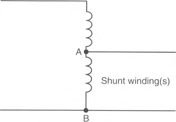
Exception: Where the rated input current of the autotransformer is less than 9 amperes, an overcurrent device rated or set at not more than 167 percent of the input current shall be permitted.
FIGURE 450.4(A) Autotransformer.
(B) Transformer Field-Connected as an Autotransformer.
A transformer field-connected as an autotransformer shall be identified for use at elevated voltage.
450.5 Grounding Autotransformers.
Grounding autotransformers covered in this section are zigzag or T-connected transformers connected to 3-phase, 3-wire ungrounded systems for the purpose of creating a 3-phase, 4-wire distribution system or providing a neutral point for grounding purposes. Such transformers shall have a continuous per-phase current rating and a continuous neutral current rating. Zigzag-connected transformers shall not be installed on the load side of any system grounding connection, including those made in accordance with 250.24(C), 250.30(A)(1), or 250.32(B), Exception No. 1.
Informational Note: The phase current in a grounding auto-transformer is one-third the neutral current.
(A) Three-Phase, 4-Wire System.
A grounding autotransformer used to create a 3-phase, 4-wire distribution system from a 3-phase, 3-wire ungrounded system shall conform to 450.5(A)(1) through (A)(4).
(1) Connections.
The transformer shall be directly connected to the ungrounded phase conductors and shall not be switched or provided with overcurrent protection that is independent of the main switch and common-trip overcurrent protection for the 3-phase, 4-wire system.
(2) Overcurrent Protection.
An overcurrent sensing device shall be provided that will cause the main switch or common-trip overcurrent protection referred to in 450.5(A)(1) to open if the load on the autotransformer reaches or exceeds 125 percent of its continuous current per-phase or neutral rating. Delayed tripping for temporary overcurrents sensed at the autotransformer overcurrent device shall be permitted for the purpose of allowing proper operation of branch or feeder protective devices on the 4-wire system.
(3) Transformer Fault Sensing.
A fault-sensing system that causes the opening of a main switch or common-trip overcurrent device for the 3-phase, 4-wire system shall be provided to guard against single-phasing or internal faults.
Informational Note: This can be accomplished by the use of two subtractive-connected donut-type current transformers installed to sense and signal when an unbalance occurs in the line current to the autotransformer of 50 percent or more of rated current.
(4) Rating.
The autotransformer shall have a continuous neutral-current rating that is not less than the maximum possible neutral unbalanced load current of the 4-wire system.
(B) Ground Reference for Fault Protection Devices.
A grounding autotransformer used to make available a specified magnitude of ground-fault current for operation of a ground-responsive protective device on a 3-phase, 3-wire ungrounded system shall conform to 450.5(B)(1) and (B)(2).
(1) Rating.
The autotransformer shall have a continuous neutral-current rating not less than the specified ground-fault current.
(2) Overcurrent Protection.
Overcurrent protection shall comply with 450.5(B)(2) (a) and (B)(2) (b).
- Operation and Interrupting Rating. An overcurrent protective device having an interrupting rating in compliance with 110.9 and that will open simultaneously all ungrounded conductors when it operates shall be applied in the grounding autotransformer branch circuit.
- Ampere Rating. The overcurrent protection shall be rated or set at a current not exceeding 125 percent of the auto-transformer continuous per-phase current rating or 42 percent of the continuous-current rating of any series-connected devices in the autotransformer neutral connection. Delayed tripping for temporary overcurrents to permit the proper operation of ground-responsive tripping devices on the main system shall be permitted but shall not exceed values that would be more than the short-time current rating of the grounding autotransformer or any series connected devices in the neutral connection thereto.
Exception: For high-impedance grounded systems covered in 250.36, where the maximum ground-fault current is designed to be not more than 10 amperes, and where the grounding autotransformer and the grounding impedance are rated for continuous duty, an overcurrent device rated not more than 20 amperes that will simultaneously open all ungrounded conductors shall be permitted to be installed on the line side of the grounding autotransformer.
(C) Ground Reference for Damping Transitory Overvoltages.
A grounding autotransformer used to limit transitory overvoltages shall be of suitable rating and connected in accordance with 450.5(A)(1).
450.6 Secondary Ties.
As used in this article, a secondary tie is a circuit operating at 1000 volts, nominal, or less between phases that connects two power sources or power supply points, such as the secondaries of two transformers. The tie shall be permitted to consist of one or more conductors per phase or neutral. Conductors connecting the secondaries of transformers in accordance with 450.7 shall not be considered secondary ties.
As used in this section, the word transformer means a transformer or a bank of transformers operating as a unit.
(A) Tie Circuits.
Tie circuits shall be provided with overcurrent protection at each end as required in Parts I, II, and VIII of Article 240.
Under the conditions described in 450.6(A)(1) and 450.6(A)(2), the overcurrent protection shall be permitted to be in accordance with 450.6(A)(3).
(1) Loads at Transformer Supply Points Only.
Where all loads are connected at the transformer supply points at each end of the tie and overcurrent protection is not provided in accordance with Parts I, II, and VIII of Article 240, the ampacity of the tie shall not be less than 67 percent of the rated secondary current of the highest rated transformer supplying the secondary tie system.
(2) Loads Connected Between Transformer Supply Points.
Where load is connected to the tie at any point between transformer supply points and overcurrent protection is not provided in accordance with Parts I, II, and VIII of Article 240, the ampacity of the tie shall not be less than 100 percent of the rated secondary current of the highest rated transformer supplying the secondary tie system.
Exception: Tie circuits comprised of multiple conductors per phase shall be permitted to be sized and protected in accordance with 450.6(A)(4).
(3) Tie Circuit Protection.
Under the conditions described in 450.6(A)(1) and (A)(2), both supply ends of each ungrounded tie conductor shall be equipped with a protective device that opens at a predetermined temperature of the tie conductor under short-circuit conditions. This protection shall consist of one of the following: (1) a fusible link cable connector, terminal, or lug, commonly known as a limiter, each being of a size corresponding with that of the conductor and of construction and characteristics according to the operating voltage and the type of insulation on the tie conductors or (2) automatic circuit breakers actuated by devices having comparable time-current characteristics.
(4) Interconnection of Phase Conductors Between Transformer Supply Points.
Where the tie consists of more than one conductor per phase or neutral, the conductors of each phase or neutral shall comply with 450.6(A)(4) (a) or (A)(4) (b).
- Interconnected. The conductors shall be interconnected in order to establish a load supply point, and the protective device specified in 450.6(A)(3) shall be provided in each ungrounded tie conductor at this point on both sides of the interconnection. The means of interconnection shall have an ampacity not less than the load to be served.
- Not Interconnected. The loads shall be connected to one or more individual conductors of a paralleled conductor tie without interconnecting the conductors of each phase or neutral and without the protection specified in 450.6(A)(3) at load connection points. Where this is done, the tie conductors of each phase or neutral shall have a combined capacity ampacity of not less than 133 percent of the rated secondary current of the highest rated transformer supplying the secondary tie system, the total load of such taps shall not exceed the rated secondary current of the highest rated transformer, and the loads shall be equally divided on each phase and on the individual conductors of each phase as far as practicable.
(5) Tie Circuit Control.
Where the operating voltage exceeds 150 volts to ground, secondary ties provided with limiters shall have a switch at each end that, when open, de-energizes the associated tie conductors and limiters. The current rating of the switch shall not be less than the rated current ampacity of the conductors connected to the switch. It shall be capable of interrupting its rated current, and it shall be constructed so that it will not open under the magnetic forces resulting from short-circuit current.
(B) Overcurrent Protection for Secondary Connections.
Where secondary ties are used, an overcurrent device rated or set at not more than 250 percent of the rated secondary current of the transformers shall be provided in the secondary connections of each transformer supplying the tie system. In addition, an automatic circuit breaker actuated by a reverse-current relay set to open the circuit at not more than the rated secondary current of the transformer shall be provided in the secondary connection of each transformer.
(C) Grounding.
Where the secondary tie system is grounded, each transformer secondary supplying the tie system shall be grounded in accordance with 250.30 for separately derived systems.
450.7 Parallel Operation.
Transformers shall be permitted to be operated in parallel and switched as a unit, provided the overcurrent protection for each transformer meets the requirements of 450.3(A) for primary and secondary protective devices over 1000 volts, or 450.3(B) for primary and secondary protective devices 1000 volts or less.
450.8 Guarding.
(A) Mechanical Protection.
Appropriate provisions shall be made to minimize the possibility of damage to transformers from external causes where the transformers are exposed to physical damage.
(B) Case or Enclosure.
Dry-type transformers shall be provided with a noncombustible moisture-resistant case or enclosure that provides protection against the accidental insertion of foreign objects.
(C) Exposed Energized Parts.
Switches or other equipment operating at 1000 volts, nominal, or less and serving only equipment within a transformer enclosure shall be permitted to be installed in the transformer enclosure if accessible to qualified persons only. All energized parts shall be guarded in accordance with 110.27 and 110.34.
(D) Voltage Warning.
The operating voltage of exposed live parts of transformer installations shall be indicated by signs or visible markings on the equipment or structures.
450.9 Ventilation.
The ventilation shall dispose of the transformer full-load heat losses without creating a temperature rise that is in excess of the transformer rating.
Informational Note No. 1: See IEEE C57.12.00-2015, General Requirements for Liquid-Immersed Distribution, Power, and Regulating Transformers, and IEEE C57.12.01-2020, General Requirements for Dry-Type Distribution and Power Transformers, for additional information.
Informational Note No. 2: See IEEE C57.110-2018, Recommended Practice for Establishing Liquid-Filled and Dry-Type Power and Distribution Transformer Capability When Supplying Nonsinusoidal Load Currents, for more information where transformers are used with nonlinear loads that have nonsinusoidal currents that can result in additional losses and transformer heating.
Transformers with ventilating openings shall be installed so that the ventilating openings are not blocked by walls or other obstructions. The required clearances shall be clearly marked on the transformer. Transformer top surfaces that are horizontal and readily accessible shall be marked to prohibit storage.
450.10 Grounding and Bonding.
(A) Dry-Type Transformer Enclosures.
Where separate equipment grounding conductors and supply-side bonding jumpers are installed, a terminal bar for all grounding and bonding conductor connections shall be secured inside the transformer enclosure. The terminal bar shall be bonded to the enclosure in accordance with 250.12 and shall not be installed on or over any vented portion of the enclosure.
Exception: Where a dry-type transformer is equipped with wire-type connections (leads), the grounding and bonding connections shall be permitted to be connected together using any of the methods in 250.8 and shall be bonded to the enclosure if of metal.
(B) Other Metal Parts.
Exposed non-current-carrying metal parts of transformer installations, including fences, guards, and so forth, shall be grounded and bonded under the conditions and in the manner specified for electrical equipment and other exposed metal parts in Parts V, VI, and VII of Article 250.
450.11 Marking.
(A) General.
Each transformer shall be provided with a name-plate giving the following information:
- Name of manufacturer
- Rated kilovolt-amperes
- Frequency
- Primary and secondary voltage
- Impedance of transformers 25 kVA and larger
- Required clearances for transformers with ventilating openings
- Amount and kind of insulating liquid where used
- For dry-type transformers, temperature class for the insulation system
(B) Source Marking.
A transformer shall be permitted to be supplied at the marked secondary voltage, provided that the installation is in accordance with the manufacturer's instructions.
450.12 Terminal Wiring Space.
The minimum wire-bending space at fixed, 1000-volt and below terminals of transformer line and load connections shall be as required in 312.6. Wiring space for pigtail connections shall conform to Table 314.16(B)(1).
450.13 Accessibility.
All transformers and transformer vaults shall be readily accessible to qualified personnel for inspection and maintenance or shall meet the requirements of 450.13(A) or 450.13(B).
(A) Open Installations.
Dry-type transformers 1000 volts, nominal, or less, located in the open on walls, columns, or structures, shall not be required to be readily accessible.
(B) Hollow Space Installations.
Dry-type transformers 1000 volts, nominal, or less and not exceeding 50 kVA shall be permitted in hollow spaces of buildings not permanently closed in by structure, provided they meet the ventilation requirements of 450.9 and separation from combustible materials requirements of 450.21(A). Transformers so installed shall not be required to be readily accessible.
450.14 Disconnecting Means.
Transformers, other than Class 2 or Class 3 transformers, shall have a disconnecting means located either in sight of the transformer or in a remote location. Where located in a remote location, the disconnecting means shall be lockable open in accordance with 110.25, and its location shall be field marked on the transformer.
450.21 Dry-Type Transformers Installed Indoors.
(A) Not Over 1121/2 kVA.
Dry-type transformers installed indoors and rated 1121/2 kVA or less shall have a separation of at least 300 mm (12 in.) from combustible material unless separated from the combustible material by a fire-resistant, heat-insulated barrier.
Exception: This rule shall not apply to transformers rated for 1000 volts, nominal, or less that are completely enclosed, except for ventilating openings.
(B) Over 1121/2 kVA.
Individual dry-type transformers of more than 1121/2 kVA rating shall be installed in a transformer room of fire-resistant construction having a minimum fire rating of 1 hour.
Exception No. 1: Transformers with Class 155 or higher insulation systems and separated from combustible material by a fire-resistant, heat-insulating barrier or by not less than 1.83 m (6 ft) horizontally and 3.7 m (12 ft) vertically shall not be required to be installed in a transformer room.
Exception No. 2: Transformers with Class 155 or higher insulation systems and completely enclosed except for ventilating openings shall not be required to be installed in a transformer room.
Informational Note: See ASTM E119-18a, Standard Test Methods for Fire Tests of Building Construction and Materials, for additional information on fire-resistance ratings.
(C) Over 35,000 Volts.
Dry-type transformers rated over 35,000 volts shall be installed in a vault complying with Part III of this article.
450.22 Dry-Type Transformers Installed Outdoors.
Dry-type transformers installed outdoors shall have a weatherproof enclosure.
Transformers exceeding 1121/2 kVA shall not be located within 300 mm (12 in.) of combustible materials of buildings unless the transformer has Class 155 insulation systems or higher and is completely enclosed except for ventilating openings.
450.23 Less-Flammable Liquid-Insulated Transformers.
Transformers insulated with listed less-flammable liquids that have a fire point of not less than 300°C shall be permitted to be installed in accordance with 450.23(A) or 450.23(B).
(A) Indoor Installations.
Indoor installations shall be permitted in accordance with one of the following:
- In Type I or Type II buildings, in areas where all of the following requirements are met:
- The transformer is rated 35,000 volts or less.
- No combustible materials are stored.
- A liquid confinement area is provided.
- The installation complies with all the restrictions provided for in the listing of the liquid.Informational Note: Such restrictions can include, but are not limited to, maximum pressure of the tank, use of a pressure relief valve, appropriate fuse types, and proper sizing of overcurrent protection.
- If an automatic fire extinguishing system and a liquid confinement area is present, provided the transformer is rated 35,000 volts or less
- If the installation complies with 450.26
(B) Outdoor Installations.
Less-flammable liquid-filled transformers shall be permitted to be installed outdoors, attached to, adjacent to, or on the roof of buildings, if installed in accordance with either of the following:
- For Type I and Type II buildings, the installation shall comply with all the restrictions provided for in the listing of the liquid.Informational Note No. 1: See NFPA 220-2021, Standard on Types of Building Construction, for definitions of Type I and Type II building construction.Informational Note No. 2: Such restrictions can include, but are not limited to, maximum pressure of the tank, use of a pressure relief valve, appropriate fuse types, and proper sizing of overcurrent protection.
- In accordance with 450.27.
Informational Note No. 3: See 450.27 for examples of additional safeguards that can be required for installations adjacent to combustible material, fire escapes, or door and window openings.
450.24 Nonflammable Fluid-Insulated Transformers.
Transformers insulated with a dielectric fluid identified as nonflammable shall be permitted to be installed indoors or outdoors. Such transformers installed indoors and rated over 35,000 volts shall be installed in a vault. Such transformers installed indoors shall be furnished with a liquid confinement area and a pressure-relief vent. The transformers shall be furnished with a means for absorbing any gases generated by arcing inside the tank, or the pressure-relief vent shall be connected to a chimney or flue that will carry such gases to an environmentally safe area.
Informational Note: Safety may be increased if fire hazard analyses are performed for such transformer installations.
For the purposes of this section, a nonflammable dielectric fluid is one that does not have a flash point or fire point and is not flammable in air.
450.25 Askarel-Insulated Transformers Installed Indoors.
Askarel-insulated transformers installed indoors and rated over 25 kVA shall be furnished with a pressure-relief vent. Where installed in a poorly ventilated place, they shall be furnished with a means for absorbing any gases generated by arcing inside the case, or the pressure-relief vent shall be connected to a chimney or flue that carries such gases outside the building. Askarel-insulated transformers rated over 35,000 volts shall be installed in a vault.
450.26 Oil-Insulated Transformers Installed Indoors.
Oil-insulated transformers installed indoors shall be installed in a vault constructed as specified in Part III of this article.
Exception No. 1: Where the total capacity does not exceed 1121/2 kVA, the vault specified in Part III of this article shall be permitted to be constructed of reinforced concrete that is not less than 100 mm (4 in.) thick.
Exception No. 2: Where the nominal voltage does not exceed 1000, a vault shall not be required if suitable arrangements are made to prevent a transformer oil fire from igniting other materials and the total capacity in one location does not exceed 10 kVA in a section of the building classified as combustible or 75 kVA where the surrounding structure is classified as fire-resistant construction.
Exception No. 3: Electric furnace transformers that have a total rating not exceeding 75 kVA shall be permitted to be installed without a vault in a building or room of fire-resistant construction, provided suitable arrangements are made to prevent a transformer oil fire from spreading to other combustible material.
Exception No. 4: A transformer that has a total rating not exceeding 75 kVA and a supply voltage of 1000 volts or less that is an integral part of charged-particle-accelerating equipment shall be permitted to be installed without a vault in a building or room of noncombustible or fire-resistant construction, provided suitable arrangements are made to prevent a transformer oil fire from spreading to other combustible material.
Exception No. 5: Transformers shall be permitted to be installed in a detached building that does not comply with Part III of this article if neither the building nor its contents present a fire hazard to any other building or property, and if the building is used only in supplying electric service and the interior is accessible only to qualified persons.
Exception No. 6: Oil-insulated transformers shall be permitted to be used without a vault in portable and mobile surface mining equipment (such as electric excavators) if each of the following conditions is met:
(1) Provision is made for draining leaking fluid to the ground.
(2) Safe egress is provided for personnel.
(3) A minimum 6-mm (1/4-in.) steel barrier is provided for personnel protection.
450.27 Oil-Insulated Transformers Installed Outdoors.
Combustible material, combustible buildings, and parts of buildings, fire escapes, and door and window openings shall be safeguarded from fires originating in oil-insulated transformers installed on roofs, attached to or adjacent to a building or combustible material.
In cases where the transformer installation presents a fire hazard, one or more of the following safeguards shall be applied according to the degree of hazard involved:
- Space separations
- Fire-resistant barriers
- Automatic fire suppression systems
- Enclosures that confine the oil of a ruptured transformer tank
Oil enclosures shall be permitted to consist of fire-resistant dikes, curbed areas or basins, or trenches filled with coarse, crushed stone. Oil enclosures shall be provided with trapped drains where the exposure and the quantity of oil involved are such that removal of oil is important.
Informational Note: See ANSI/IEEE C2-2017, National Electrical Safety Code, for additional information on transformers installed on poles or structures or underground.
450.28 Modification of Transformers.
When modifications are made to a transformer in an existing installation that change the type of the transformer with respect to Part II of this article, such transformer shall be marked to show the type of insulating liquid installed, and the modified transformer installation shall comply with the applicable requirements for that type of transformer.
450.41 Location.
Vaults shall be located where they can be ventilated to the outside air without using flues or ducts wherever such an arrangement is practicable.
450.42 Walls, Roofs, and Floors.
The walls and roofs of vaults shall be constructed of materials that have approved structural strength for the conditions with a minimum fire resistance of 3 hours. The floors of vaults in contact with the earth shall be of concrete that is not less than 100 mm (4 in.) thick, but, where the vault is constructed with a vacant space or other stories below it, the floor shall have approved structural strength for the load imposed thereon and a minimum fire resistance of 3 hours. For the purposes of this section, studs and wallboard construction shall not be permitted.
Exception: Where transformers are protected with automatic sprinkler, water spray, carbon dioxide, or halon, construction of 1-hour rating shall be permitted.
Informational Note No. 1: See ASTM E119-20, Standard Test Methods for Fire Tests of Building Construction and Materials, for additional information.
Informational Note No. 2: A typical 3-hour construction is 150 mm (6 in.) thick reinforced concrete.
450.43 Doorways.
(A) Type of Door.
Each doorway leading into a vault from the building interior shall be provided with a tight-fitting door that has a minimum fire rating of 3 hours. The authority having jurisdiction shall be permitted to require such a door for an exterior wall opening where conditions warrant.
Exception: Where transformers are protected with automatic sprinkler, water spray, carbon dioxide, or halon, construction of 1-hour rating shall be permitted.
Informational Note: See NFPA 80-2019, Standard for Fire Doors and Other Opening Protectives, for additional information.
(B) Sills.
A door sill or curb that is of an approved height that will confine the oil from the largest transformer within the vault shall be provided, and in no case shall the height be less than 100 mm (4 in.).
(C) Accessibility.
Doors shall be equipped with locks, and doors shall be kept locked, with access being allowed only to qualified persons. Personnel doors shall be capable of opening not less than 90 degrees in the direction of egress and be equipped with listed fire exit hardware.
450.45 Ventilation Openings.
Where required by 450.9, openings for ventilation shall be provided in accordance with 450.45(A) through (F).
(A) Location.
Ventilation openings shall be located as far as possible from doors, windows, fire escapes, and combustible material.
(B) Arrangement.
A vault ventilated by natural circulation of air shall be permitted to have roughly half of the total area of openings required for ventilation in one or more openings near the floor and the remainder in one or more openings in the roof or in the sidewalls near the roof, or all of the area required for ventilation shall be permitted in one or more openings in or near the roof.
(C) Size.
For a vault ventilated by natural circulation of air to an outdoor area, the combined net area of all ventilating openings, after deducting the area occupied by screens, gratings, or louvers, shall not be less than 1900 mm2 (3 in.2) per kVA of transformer capacity in service, and in no case shall the net area be less than 0.1 m2 (1 ft2) for any capacity under 50 kVA.
(D) Covering.
Ventilation openings shall be covered with durable gratings, screens, or louvers, according to the treatment required in order to avoid unsafe conditions.
(E) Dampers.
All ventilation openings to the indoors shall be provided with automatic closing fire dampers that operate in response to a vault fire. Such dampers shall possess a standard fire rating of not less than 11/2 hours.
Informational Note: See ANSI/UL 555-2020, Standard for Fire Dampers, for additional information on fire dampers.
(F) Ducts.
Ventilating ducts shall be constructed of fire-resistant material.
450.46 Drainage.
Where practicable, vaults containing more than 100 kVA transformer capacity shall be provided with a drain or other means that will carry off any accumulation of oil or water in the vault unless local conditions make this impracticable. The floor shall be pitched to the drain where provided.
450.47 Water Pipes and Accessories.
Any pipe or duct system foreign to the electrical installation shall not enter or pass through a transformer vault. Piping or other facilities provided for vault fire protection, or for transformer cooling, shall not be considered foreign to the electrical installation.
Article 455
Phase Converters
455.3 Other Articles.
Phase converters shall comply with this article and with the applicable provisions of other articles of this Code.
455.4 Marking.
Each phase converter shall be provided with a permanent nameplate indicating the following:
- Manufacturer's name
- Rated input and output voltages
- Frequency
- Rated single-phase input full-load amperes
- Rated minimum and maximum single load in kilovolt-amperes (kVA) or horsepower
- Maximum total load in kilovolt-amperes (kVA) or horsepower
- For a rotary-phase converter, 3-phase amperes at full load
455.5 Equipment Grounding Connection.
A means for attachment of an equipment grounding conductor termination in accordance with 250.8 shall be provided.
455.6 Conductors.
(A) Ampacity.
The ampacity of the single-phase supply conductors shall be determined by 455.6(A)(1) or (A)(2).
Informational Note: Single-phase conductors sized to prevent a voltage drop not exceeding 3 percent from the source of supply to the phase converter may help ensure proper starting and operation of motor loads.
(1) Variable Loads.
Where the loads to be supplied are variable, the conductor ampacity shall not be less than 125 percent of the phase converter nameplate single-phase input full-load amperes.
(2) Fixed Loads.
Where the phase converter supplies specific fixed loads, and the conductor ampacity is less than 125 percent of the phase converter nameplate single-phase input full-load amperes, the conductors shall have an ampacity not less than 250 percent of the sum of the full-load, 3-phase current rating of the motors and other loads served where the input and output voltages of the phase converter are identical. Where the input and output voltages of the phase converter are different, the current as determined by this section shall be multiplied by the ratio of output to input voltage.
455.7 Overcurrent Protection.
The single-phase supply conductors and phase converter shall be protected from over-current by 455.7(A) or (B). Where the required fuse or nonadjustable circuit breaker rating or settings of adjustable circuit breakers do not correspond to a standard rating or setting, a higher rating or setting that does not exceed the next higher standard rating shall be permitted.
(A) Variable Loads.
Where the loads to be supplied are variable, overcurrent protection shall be set at not more than 125 percent of the phase converter nameplate single-phase input full-load amperes.
(B) Fixed Loads.
Where the phase converter supplies specific fixed loads and the conductors are sized in accordance with 455.6(A)(2), the conductors shall be protected in accordance with their ampacity. The overcurrent protection determined from this section shall not exceed 125 percent of the phase converter nameplate single-phase input amperes.
455.8 Disconnecting Means.
Means shall be provided to disconnect simultaneously all ungrounded single-phase supply conductors to the phase converter.
(B) Type.
The disconnecting means shall be a switch rated in horsepower, a circuit breaker, or a molded-case switch. Where only nonmotor loads are served, an ampere-rated switch shall be permitted.
(C) Rating.
The ampere rating of the disconnecting means shall not be less than 115 percent of the rated maximum single-phase input full-load amperes or, for specific fixed loads, shall be permitted to be selected from 455.8(C)(1) or (C)(2).
(1) Current Rated Disconnect.
The disconnecting means shall be a circuit breaker or molded-case switch with an ampere rating not less than 250 percent of the sum of the following:
- Full-load, 3-phase current ratings of the motors
- Other loads served
(2) Horsepower Rated Disconnect.
The disconnecting means shall be a switch with a horsepower rating. The equivalent locked rotor current of the horsepower rating of the switch shall not be less than 200 percent of the sum of the following:
- Nonmotor loads
- The 3-phase, locked-rotor current of the largest motor as determined from Table 430.251 (B)
- The full-load current of all other 3-phase motors operating at the same time
(D) Voltage Ratios.
The calculations in 455.8(C) shall apply directly where the input and output voltages of the phase converter are identical. Where the input and output voltages of the phase converter are different, the current shall be multiplied by the ratio of the output to input voltage.
455.9 Connection of Single-Phase Loads.
Where single-phase loads are connected on the load side of a phase converter, they shall not be connected to the manufactured phase.
455.10 Terminal Housings.
A terminal housing in accordance with the provisions of 430.12 shall be provided on a phase converter.
455.20 Disconnecting Means.
The single-phase disconnecting means for the input of a static phase converter shall be permitted to serve as the disconnecting means for the phase converter and a single load if the load is within sight of the disconnecting means.
455.21 Start-Up.
Power to the utilization equipment shall not be supplied until the rotary-phase converter has been started.
455.22 Power Interruption.
Utilization equipment supplied by a rotary-phase converter shall be controlled in such a manner that power to the equipment will be disconnected in the event of a power interruption.
Informational Note: Magnetic motor starters, magnetic contactors, and similar devices, with manual or time delay restarting for the load, provide restarting after power interruption.
Article 460
Capacitors
460.1 Scope.
This article covers the installation of capacitors on electrical circuits.
Surge capacitors or capacitors included as a component part of other apparatus and conforming with the requirements of such apparatus are excluded from these requirements.
460.3 Enclosing and Guarding.
(A) Containing More Than 11 L (3 Gal) of Flammable Liquid.
Capacitors containing more than 11 L (3 gal) of flammable liquid shall be enclosed in vaults or outdoor fenced enclosures complying with Article 110, Part III. This limit shall apply to any single unit in an installation of capacitors.
(B) Accidental Contact.
Where capacitors are accessible to unauthorized and unqualified persons, they shall be enclosed, located, or guarded so that persons cannot come into accidental contact or bring conducting materials into accidental contact with exposed energized parts, terminals, or buses associated with them. However, no additional guarding is required for enclosures accessible only to authorized and qualified persons.
460.6 Discharge of Stored Energy.
Capacitors shall be provided with a means of discharging stored energy.
(A) Time of Discharge.
The residual voltage of a capacitor shall be reduced to 50 volts, nominal, or less within 1 minute after the capacitor is disconnected from the source of supply.
(B) Means of Discharge.
The discharge circuit shall be either permanently connected to the terminals of the capacitor or capacitor bank or provided with automatic means of connecting it to the terminals of the capacitor bank on removal of voltage from the line. Manual means of switching or connecting the discharge circuit shall not be used.
460.8 Conductors.
(A) Ampacity.
The ampacity of capacitor circuit conductors shall not be less than 135 percent of the rated current of the capacitor. The ampacity of conductors that connect a capacitor to the terminals of a motor or to motor circuit conductors shall not be less than one-third the ampacity of the motor circuit conductors and in no case less than 135 percent of the rated current of the capacitor.
(B) Overcurrent Protection.
An overcurrent device shall be provided in each ungrounded conductor for each capacitor bank. The rating or setting of the overcurrent device shall be as low as practicable.
Exception: A separate overcurrent device shall not be required for a capacitor connected on the load side of a motor overload protective device.
(C) Disconnecting Means.
A disconnecting means shall be provided in each ungrounded conductor for each capacitor bank and shall meet the following requirements:
- The disconnecting means shall open all ungrounded conductors simultaneously.
- The disconnecting means shall be permitted to disconnect the capacitor from the line as a regular operating procedure.
- The rating of the disconnecting means shall not be less than 135 percent of the rated current of the capacitor.
Exception: A separate disconnecting means shall not be required where a capacitor is connected on the load side of a motor controller.
460.9 Rating or Setting of Motor Overload Device.
Where a motor installation includes a capacitor connected on the load side of the motor overload device, the rating or setting of the motor overload device shall be based on the improved power factor of the motor circuit.
The effect of the capacitor shall be disregarded in determining the motor circuit conductor rating in accordance with 430.22.
460.10 Grounding.
Capacitor cases shall be connected to the equipment grounding conductor.
Exception: Capacitor cases shall not be connected to the equipment grounding conductor where the capacitor units are supported on a structure designed to operate at other than ground potential.
460.12 Marking.
Each capacitor shall be provided with a nameplate giving the name of the manufacturer, rated voltage, frequency, kilovar or amperes, number of phases, and, if filled with a combustible liquid, the volume of liquid. Where filled with a nonflammable liquid, the nameplate shall so state. The nameplate shall also indicate whether a capacitor has a discharge device inside the case.
460.24 Switching.
(A) Load Current.
Switches shall be rated for switching of capacitive loads. Capacitor switch operation shall open all ungrounded conductors and the switch shall be capable of the following:
- Carrying continuously not less than 135 percent of the rated current of the capacitor installation
- Interrupting the maximum continuous load current of each capacitor, capacitor bank, or capacitor installation that will be switched as a unit
- Withstanding the maximum inrush current, including contributions from adjacent capacitor installations
- Carrying currents due to faults on capacitor side of switch
(B) Isolation.
(2) Isolating or Disconnecting Switches With No Interrupting Rating.
Isolating or disconnecting switches (with no interrupting rating) shall be interlocked with the load-interrupting device or be provided with prominently displayed caution signs in accordance with 495.22 to prevent switching load current.
(C) Additional Requirements for Series Capacitors.
The proper switching sequence shall be ensured by use of one of the following:
- Mechanically sequenced isolating and bypass switches
- Interlocks
- Switching procedure prominently displayed at the switching location
460.25 Overcurrent Protection.
(A) Provided to Detect and Interrupt Fault Current.
A means shall be provided to detect and interrupt fault current likely to cause dangerous pressure within an individual capacitor.
(C) Protected Individually or in Groups.
Capacitors shall be permitted to be protected individually or in groups.
460.26 Identification.
Each capacitor shall be provided with a permanent nameplate giving the manufacturer's name, rated voltage, frequency, kilovar or amperes, number of phases, and the volume of liquid identified as flammable, if such is the case.
460.27 Grounding.
Capacitor cases shall be connected to the equipment grounding conductor. If the capacitor neutral point is connected to a grounding electrode conductor, the connection shall be made in accordance with Part III of Article 250.
Exception: Capacitor cases shall not be connected to the equipment grounding conductor where the capacitor units are supported on a structure designed to operate at other than ground potential.
460.28 Means for Discharge.
(A) Means to Reduce the Residual Voltage.
A means shall be provided to reduce the residual voltage of a capacitor to 50 volts or less within 5 minutes after the capacitor is disconnected from the source of supply.
(B) Connection to Terminals.
A discharge circuit shall be either permanently connected to the terminals of the capacitor or provided with automatic means of connecting it to the terminals of the capacitor bank after disconnection of the capacitor from the source of supply. The windings of motors, transformers, or other equipment directly connected to capacitors without a switch or overcurrent device interposed shall meet the requirements of 460.28(A).
Article 470
Resistors and Reactors
470.1 Scope.
This article covers the installation of separate resistors and reactors on electrical circuits.
Exception: This article does not cover resistors and reactors that are component parts of other apparatus.
470.2 Reconditioned Equipment.
(A) Resistors.
Reconditioned resistors shall not be permitted.
(B) Reactors.
Reconditioned reactors shall be permitted.
470.10 Location.
Resistors and reactors shall not be placed where exposed to physical damage.
470.11 Space Separation.
A thermal barrier shall be required if the space between the resistors or reactors and any combustible material is less than 305 mm (12 in.).
470.12 Conductor Insulation.
Insulated conductors used for connections between resistance elements and controllers shall be suitable for an operating temperature of not less than 90°C (194°F).
Exception: Other conductor insulations shall be permitted for the motor starting service.
470.20 General.
(A) Protected Against Physical Damage.
Resistors and reactors shall be protected against physical damage.
(C) Combustible Materials.
Resistors and reactors shall not be installed in close enough proximity to combustible materials to constitute a fire hazard and shall have a clearance of not less than 305 mm (12 in.) from combustible materials.
(D) Clearances.
Clearances from resistors and reactors to grounded surfaces shall be adequate for the voltage involved.
(E) Temperature Rise From Induced Circulating Currents.
Metallic enclosures of reactors and adjacent metal parts shall be installed so that the temperature rise from induced circulating currents is not hazardous to personnel or does not constitute a fire hazard.
470.21 Grounding.
Resistor and reactor cases or enclosures shall be connected to the equipment grounding conductor.
Exception: Resistor or reactor cases or enclosures supported on a structure designed to operate at other than ground potential shall not be connected to the equipment grounding conductor.
470.22 Oil-Filled Reactors.
Installation of oil-filled reactors, in addition to the above requirements, shall comply with applicable requirements of Part II and Part III of Article 450.
Article 480
Stationary Standby Batteries
480.1 Scope.
This article applies to all installations of stationary standby batteries having a capacity greater than 3.6 MJ (1 kWh).
Informational Note No. 1: See Article 706 for installations that do not meet the definition of stationary standby batteries.
Informational Note No. 2: The following standards are frequently referenced for the installation of stationary batteries:
- IEEE 484, Recommended Practice for Installation Design and Installation of Vented Lead-Acid Batteries for Stationary Applications
- IEEE 485, Recommended Practice for Sizing Vented Lead-Acid Storage Batteries for Stationary Applications
- IEEE 1145, Recommended Practice for Installation and Maintenance of Nickel-Cadmium Batteries for Photovoltaic (PV) Systems
- IEEE 1187, IEEE Recommended Practice for Installation Design, and Installation of Valve-Regulated Lead-Acid Batteries for Stationary Applications
- IEEE 1375, IEEE Guide for the Protection of Stationary Battery Systems
- IEEE 1578, Recommended Practice for Stationary Battery Electrolyte Spill Containment and Management
- IEEE 1635/ASHRAE 21, Guide for the Ventilation and Thermal Management of Batteries for Stationary Applications
- UL 1973, Standard for Batteries for Use in Stationary, Vehicle Auxiliary Power, and Light Electric Rail (LER) Applications
- UL Subject 2436, Outline of Investigation for Spill Containment for Stationary Lead Acid Battery Systems
- UL 1989, Standard for Standby Batteries
- UL Subject 1974, Standard for Evaluation of Repurposed Batteries
- NFPA 855-2020, Standard for the Installation of Stationary Energy Storage Systems
480.4 Battery and Cell Terminations.
(B) Intercell and Intertier Conductors and Connections.
The ampacity of field-assembled intercell and intertier connectors and conductors shall be of such cross-sectional area that the temperature rise under maximum load conditions and at maximum ambient temperature shall not exceed the safe operating temperature of the conductor insulation or of the material of the conductor supports.
Informational Note: Conductors sized to prevent a voltage drop exceeding 3 percent of maximum anticipated load, and where the maximum total voltage drop to the furthest point of connection does not exceed 5 percent, may not be appropriate for all battery applications. IEEE 1375-2003, Guide for the Protection of Stationary Battery Systems, provides guidance for overcurrent protection and associated cable sizing.
(C) Battery Terminals.
(D) Accessibility.
The terminals of all cells or multicell units shall be readily accessible for readings, inspections, and cleaning where required by the equipment design. One side of transparent battery containers shall be readily accessible for inspection of the internal components.
480.6 Overcurrent Protection for Prime Movers.
Overcurrent protection shall not be required for conductors from a battery with a voltage of 60 volts dc or less if the battery provides power for starting, ignition, or control of prime movers. Section 300.3 shall not apply to these conductors.
480.7 DC Disconnect Methods.
(A) Disconnecting Means.
A disconnecting means shall be provided for all ungrounded conductors derived from a stationary standby battery with a voltage over 60 volts dc. A disconnecting means shall be readily accessible and located within sight of the stationary standby battery.
Informational Note: See 240.21 (H) for information on the location of the overcurrent device for battery conductors.
(B) Emergency Disconnect.
For one-family and two-family dwellings, a disconnecting means or its remote control for a stationary standby battery shall be located at a readily accessible location outside the building for emergency use. The disconnect shall be labeled as follows:
EMERGENCY DISCONNECT
(C) Disconnection of Series Battery Circuits.
Battery circuits exceeding 240 volts dc nominal between conductors or to ground and subject to field servicing shall have provisions to disconnect the series-connected strings into segments not exceeding 240 volts dc nominal for maintenance by qualified persons. Non-load-break bolted or plug-in disconnects shall be permitted.
(D) Remote Actuation.
Where a disconnecting means, located in accordance with 480.7(A), is provided with remote controls to activate the disconnecting means and the controls for the disconnecting means are not located within sight of the stationary standby battery, the disconnecting means shall be capable of being locked in the open position, in accordance with 110.25, and the location of the controls shall be field marked on the disconnecting means.
(E) Busway.
Where a dc busway system is installed, the disconnecting means shall be permitted to be incorporated into the busway.
(F) Notification.
The disconnecting means shall be legibly marked in the field. A label with the marking shall be placed in a conspicuous location near the battery if a disconnecting means is not provided. The marking shall be of sufficient durability to withstand the environment involved and shall include the following:
- Nominal battery voltage
- Available fault current derived from the stationary standby batteryInformational Note No. 1: Battery equipment suppliers can provide information about available fault current on specific battery models.
- An arc flash label in accordance with acceptable industry practiceInformational Note No. 2: See NFPA 70E-2021, Standard for Electrical Safety in the Workplace, for assistance in determining the severity of potential exposure, planning safe work practices, arc flash labeling, and selecting personal protective equipment.
- Date the calculation was performed
Exception: List items (2), (3), and (4) shall not apply to one- and two-family dwellings.
480.9 Battery Support Systems.
For battery chemistries with corrosive electrolyte, the structure that supports the battery shall be resistant to deteriorating action by the electrolyte. Metallic structures shall be provided with nonconducting support members for the cells, or shall be constructed with a continuous insulating material. Paint alone shall not be considered as an insulating material.
480.10 Battery Locations.
(A) Ventilation.
Provisions appropriate to the battery technology shall be made for sufficient diffusion and ventilation of gases from the battery, if present, to prevent the accumulation of an explosive mixture.
Informational Note No. 1: See NFPA 1-2021, Fire Code, Chapter 52, for ventilation considerations for specific battery chemistries.
Informational Note No. 2: Some battery technologies do not require ventilation.
(C) Spaces About Stationary Standby Batteries.
Spaces about stationary standby batteries shall comply with 110.26 and 110.34. Working space shall be measured from the edge of the battery cabinet, racks, or trays.
For battery racks, there shall be a minimum clearance of 25 mm (1 in.) between a cell container and any wall or structure on the side not requiring access for maintenance. Battery stands shall be permitted to contact adjacent walls or structures, provided that the battery shelf has a free air space for not less than 90 percent of its length.
(D) Top Terminal Batteries.
(E) Egress.
Personnel doors intended for entrance to, and egress from, rooms designated as battery rooms shall open at least 90 degrees in the direction of egress and shall be equipped with listed panic or listed fire exit hardware.
(G) Illumination.
Illumination shall be provided for working spaces containing stationary standby batteries. The lighting outlets shall not be controlled by automatic means only. Additional lighting outlets shall not be required where the work space is illuminated by an adjacent light source. The location of luminaires shall not result in the following:
480.12 Battery Interconnections.
Flexible cables, as identified in Table 400.4, in sizes 2/0 AWG and larger shall be permitted within the battery enclosure from battery terminals to a nearby junction box where they shall be connected to an approved wiring method. Flexible battery cables shall also be permitted between batteries and cells within the battery enclosure. Such cables shall be listed and identified for the environmental conditions. Flexible, fine-stranded cables shall only be used with terminals, lugs, devices, or connectors in accordance with 110.14.
480.13 Ground-Fault Detection.
Battery circuits exceeding 100 volts between the conductors or to ground shall be permitted to operate with ungrounded conductors, provided a ground-fault detector and indicator is installed to monitor for ground faults.
Article 495
Equipment Over 1000 Volts AC, 1500 Volts DC, Nominal
495.1 Scope.
This article covers the general requirements for equipment operating at more than 1000 volts ac, 1500 volts dc, nominal.
Informational Note No. 1: See NFPA 70E-2021, Standard for Electrical Safety in the Workplace, for electrical safety requirements for employee workplaces.
Informational Note No. 2: See ANSI Z535.4-2011, Product Signs and Safety Labels, for further information on hazard signs and labels.
Informational Note No. 3: See IEEE 3001.5-2013, Recommended Practice for the Application of Power Distribution Apparatus in Industrial and Commercial Power Systems, for information regarding power distribution apparatus.
495.3 Other Articles.
(A) Oil-Filled Equipment.
Installation of electrical equipment containing more than 38 L (10 gal) of flammable oil per unit shall meet the requirements of Parts II and III of Article 450.
495.22 Isolating Means.
Means shall be provided to completely isolate an item of equipment from all ungrounded conductors. The use of isolating switches shall not be required where there are other ways of de-energizing the equipment for inspection and repairs, such as draw-out-type switchgear units and removable truck panels.
495.23 Voltage Regulators.
Proper switching sequence for regulators shall be ensured by use of one of the following:
- Mechanically sequenced regulator bypass switch(es)
- Mechanical interlocks
- Switching procedure prominently displayed at the switching location
495.24 Minimum Space Separation.
In field-fabricated installations, the minimum air separation between bare live conductors and between such conductors and adjacent grounded surfaces shall not be less than the values given in Table 495.24. These values shall not apply to interior portions or exterior terminals of equipment designed, manufactured, and tested in accordance with accepted national standards.
Table 495.24 Minimum Clearance of Live Parts.
| Nominal Voltage Rating (kV) | Impulse Withstand, Basic Impulse Level (BIL) (kV) | Minimum Clearance of Live Parts | ||||||||
|---|---|---|---|---|---|---|---|---|---|---|
| Phase-to-Phase | Phase-to-Ground | |||||||||
| Indoors | Outdoors | Indoors | Outdoors | |||||||
| Indoors | Outdoors | mm | in. | mm | in. | mm | in. | mm | in. | |
| 2.4—4.16 | 60 | 95 | 115 | 4.5 | 180 | 7 | 80 | 3.0 | 155 | 6 |
| 7.2 | 75 | 95 | 140 | 5.5 | 180 | 7 | 105 | 4.0 | 155 | 6 |
| 13.8 | 95 | 110 | 195 | 7.5 | 305 | 12 | 130 | 5.0 | 180 | 7 |
| 14.4 | 110 | 110 | 230 | 9.0 | 305 | 12 | 170 | 6.5 | 180 | 7 |
| 23 | 125 | 150 | 270 | 10.5 | 385 | 15 | 190 | 7.5 | 255 | 10 |
| 34.5 | 150 | 150 | 320 | 12.5 | 385 | 15 | 245 | 9.5 | 255 | 10 |
| 200 | 200 | 460 | 18.0 | 460 | 18 | 335 | 13.0 | 335 | 13 | |
| 46 | - | 200 | - | - | 460 | 18 | - | - | 335 | 13 |
| - | 250 | - | - | 535 | 21 | - | - | 435 | 17 | |
| 69 | - | 250 | - | - | 535 | 21 | - | - | 435 | 17 |
| - | 350 | - | - | 790 | 31 | - | - | 635 | 25 | |
| 115 | - | 550 | - | - | 1350 | 53 | - | - | 1070 | 42 |
| 138 | - | 550 | - | - | 1350 | 53 | - | - | 1070 | 42 |
| - | 650 | - | - | 1605 | 63 | - | - | 1270 | 50 | |
| 161 | - | 650 | - | - | 1605 | 63 | - | - | 1270 | 50 |
| - | 750 | - | - | 1830 | 72 | - | - | 1475 | 58 | |
| 230 | - | 750 | - | - | 1830 | 72 | - | - | 1475 | 58 |
| - | 900 | - | - | 2265 | 89 | - | - | 1805 | 71 | |
| - | 1050 | - | - | 2670 | 105 | - | - | 2110 | 83 | |
Note: The values given are the minimum clearance for rigid parts and bare conductors under favorable service conditions. They shall be increased for conductor movement or under unfavorable service conditions or wherever space limitations permit. The selection of the associated impulse withstand voltage for a particular system voltage is determined by the characteristics of the overvoltage (surge) protective equipment.
495.25 Backfeed.
(A) Sign.
A permanent sign in accordance with 110.21(B) shall be installed on the disconnecting means enclosure or immediately adjacent to open disconnecting means with the following words or equivalent:
(B) Diagram.
A permanent and legible single-line diagram of the local switching arrangement, clearly identifying each point of connection to the high-voltage section, shall be provided within sight of each point of connection.
495.30 General.
Part III covers assemblies of switchgear and industrial control equipment, including, but not limited to, switches and interrupting devices and their control, metering, protection, and regulating equipment where they are an integral part of the assembly, with associated interconnections and supporting structures.
495.31 Arrangement of Devices in Assemblies.
Arrangement of devices in assemblies shall be such that individual components can safely perform their intended function without adversely affecting the safe operation of other components in the assembly.
495.32 Guarding of High-Voltage Energized Parts Within a Compartment.
Where access for other than visual inspection is required to a compartment that contains energized high-voltage parts, barriers shall be provided to prevent accidental contact by persons, tools, or other equipment with energized parts. Exposed live parts shall only be permitted in compartments accessible to qualified persons. Fuses and fuseholders designed to enable future replacement without de-energizing the fuseholder shall only be permitted for use by qualified persons.
495.34 Clearance for Cable Conductors Entering Enclosure.
The unobstructed space opposite terminals or opposite race-ways or cables entering a switchgear or control assembly shall be approved for the type of conductor and method of termination.
495.35 Accessibility of Energized Parts.
(A) High-Voltage Equipment.
Doors that would provide unqualified persons access to high-voltage energized parts shall be locked. Permanent signs in accordance with 110.21(B) shall be installed on panels or doors that provide access to live parts over 1000 volts and shall read DANGER - HIGH VOLTAGE - KEEP OUT.
(B) Control Equipment.
Where operating at 1000 volts, nominal, or less, control equipment, relays, motors, and the like shall not be installed in compartments with high-voltage parts or high-voltage wiring, unless both of the following apply:
- The access means is interlocked with the high-voltage switch or disconnecting means to prevent the access means from being opened or removed when the high-voltage switch is in the closed position or a withdrawable disconnecting means is in the connected position.
- All high-voltage parts or high-voltage wiring in the compartment that remains energized when a fixed mounted high-voltage switch is in the open position or a withdrawable disconnecting means is in the isolating (fully withdrawn) position are protected by insulating or grounded metal barriers to prevent accidental contact with energized high-voltage parts or wiring.
(C) High-Voltage Instruments or Control Transformers and Space Heaters.
High-voltage instrument or control transformers and space heaters shall be permitted to be installed in the high-voltage compartment without access restrictions beyond those that apply to the high-voltage compartment generally.
495.37 Equipment Grounding Connections.
The metal cases or frames, or both, such as those of instruments, relays, meters, and instrument and control transformers, located in or on switchgear or control assemblies, and the frames of switchgear and control assemblies shall be connected to an equipment grounding conductor or, where permitted, the grounded conductor, in accordance with 250.190.
495.38 Door Stops and Cover Plates.
External hinged doors or covers shall be provided with stops to hold them in the open position. Cover plates intended to be removed for inspection of energized parts or wiring shall be equipped with lifting handles and shall not exceed 1.1 nr (12 ft2) in area or 27 kg (60 lb) in weight, unless they are hinged and bolted or locked.
495.39 Gas Discharge From Interrupting Devices.
Gas discharged during operating of interrupting devices shall be directed so as not to endanger personnel.
495.40 Visual Inspection Windows.
Windows intended for visual inspection of disconnecting switches or other devices shall be of suitable transparent material.
495.41 Location of Industrial Control Equipment.
Routinely operated industrial control equipment shall meet the requirements of 495.41 (A) unless infrequently operated, as covered in 495.41 (B).
(A) Control and Instrument Transfer Switch Handles or Push Buttons.
Control and instrument transfer switch handles or push buttons shall be in a readily accessible location at an elevation of not over 2.0 m (6 ft 7 in.).
Exception: Operating handles requiring more than 23 kg (50 lb) of force shall be located no higher than 1.7 m (66 in.) in either the open or closed position.
(B) Infrequently Operated Devices.
Where operating handles for such devices as draw-out fuses, fused potential or control transformers and their primary disconnects, and bus transfer and isolating switches are only operated infrequently, the handles shall be permitted to be located where they are safely operable and serviceable from a portable platform.
495.42 Interlocks - Interrupter Switches.
Interrupter switches equipped with stored energy mechanisms shall have mechanical interlocks to prevent access to the switch compartment unless the stored energy mechanism is in the discharged or blocked position.
495.44 Fused Interrupter Switches.
(A) Supply Terminals.
The supply terminals of fused interrupter switches shall be installed at the top of the switch enclosure or, if the terminals are located elsewhere, the equipment shall have barriers installed to prevent persons from accidentally contacting energized parts or dropping tools or fuses into energized parts.
(C) Switching Mechanism.
The switching mechanism shall be arranged to be operated from a location outside the enclosure where the operator is not exposed to energized parts and shall be arranged to open all ungrounded conductors of the circuit simultaneously with one operation. Switches shall be lockable open in accordance with 110.25.
495.45 Circuit Breakers - Interlocks.
(A) Circuit Breakers.
Circuit breakers equipped with stored energy mechanisms shall be designed to prevent the release of the stored energy unless the mechanism has been fully charged.
(B) Mechanical Interlocks.
Mechanical interlocks shall be provided in the housing to prevent the complete withdrawal of the circuit breaker from the housing when the stored energy mechanism is in the fully charged position, unless a suitable device is provided to block the closing function of the circuit breaker before complete withdrawal.
495.46 Circuit Breaker Locking.
Circuit breakers shall be capable of being locked in the open position or, if they are installed in a draw-out mechanism, that mechanism shall be capable of being locked in such a position that the mechanism cannot be moved into the connected position. In either case, the provision for locking shall be lockable open in accordance with 110.25.
495.47 Switchgear Used as Service Equipment.
Switchgear installed as high-voltage service equipment shall include a ground bus for the connection of service cable shields and to facilitate the attachment of safety grounds for personnel protection. This bus shall be extended into the compartment where the service conductors are terminated. Where the compartment door or panel provides access to parts that can only be de-energized and visibly isolated by the serving utility, the warning sign required by 495.35(A) shall include a notice that access is limited to the serving utility or is permitted only following an authorization of the serving utility.
495.48 Substation Design, Documentation, and Required Diagram.
(A) Design and Documentation.
Substations shall be designed by a qualified licensed professional engineer. Where components or the entirety of the substation is listed by a qualified electrical testing laboratory, documentation of internal design features subject to the listing investigation shall not be required. The design shall address but not be limited to the following topics, and the documentation of this design shall be made available to the authority having jurisdiction:
- Clearances and exits
- Electrical enclosures
- Securing and support of electrical equipment
- Fire protection
- Safety ground connection provisions
- Guarding live parts
- Transformers and voltage regulation equipment
- Conductor insulation, electrical and mechanical protection, isolation, and terminations
- Application, arrangement, and disconnection of circuit breakers, switches, and fuses
- Provisions for oil-filled equipment
- Switchgear
- Overvoltage (surge) protection equipment
(B) Diagram.
A permanent, single-line diagram of the switchgear shall be provided in a readily visible location within the same room or enclosed area with the switchgear and shall clearly identify the following:
- Interlocks
- Isolation means
- All possible sources of voltage to the installation under normal or emergency conditions
The marking on the switchgear shall cross-reference the diagram.
Exception: Where the equipment consists solely of a single cubicle or metal-enclosed substation containing only one high-voltage, switching device, diagrams shall not be required.
495.49 Reconditioned Switchgear.
Reconditioned switchgear, or sections of switchgear, shall be permitted. If equipment has been damaged by fire, products of combustion, or water, it shall be specifically evaluated by its manufacturer or a qualified testing laboratory prior to being returned to service.
495.61 General.
(A) Covered.
The provisions of this part shall apply to installations and use of high-voltage power distribution and utilization equipment that is portable, mobile, or both, and include but not be limited to the following:
- Substations and switch houses mounted on skids
- Trailers or cars
- Mobile shovels
- Draglines
- Cranes
- Hoists
- Drills
- Dredges
- Compressors
- Pumps
- Conveyors
- Underground excavators
(C) Protection.
Approved enclosures or guarding, or both, shall be provided to protect portable and mobile equipment from physical damage.
(D) Disconnecting Means.
Disconnecting means shall be installed for mobile and portable high-voltage equipment according to the requirements of Part VIII of Article 230 and shall disconnect all ungrounded conductors.
495.62 Overcurrent Protection.
Motors driving single or multiple dc generators supplying a system operating on a cyclic load basis shall not require overload protection if the thermal rating of the ac drive motor cannot be exceeded under any operating condition. The branch-circuit protective device(s) shall provide short-circuit and locked-rotor protection and shall be permitted to be external to the equipment.
495.63 Enclosures.
All energized switching and control parts shall be enclosed in grounded metal cabinets or enclosures. These cabinets or enclosures shall be marked DANGER - HIGH VOLTAGE - KEEP OUT and shall be locked so that only authorized and qualified persons can enter. The danger marking(s) or label(s) shall comply with 110.21(B). Circuit breakers and protective equipment shall have the operating means projecting through the metal cabinet or enclosure so these units can be reset without opening locked doors. With doors closed, safe access for normal operation of these units shall be provided.
495.65 Power Cable Connections to Mobile Machines.
A metallic enclosure shall be provided on the mobile machine for enclosing the terminals of the power cable. The enclosure shall include terminal connections to the machine frame for the equipment grounding conductor. Ungrounded conductors shall be attached to insulators or be terminated in approved high-voltage cable couplers (which include equipment grounding conductor connectors) of proper voltage and ampere rating. The method of cable termination used shall prevent any strain or pull on the cable from stressing the electrical connections. The enclosure shall have provision for locking so that only authorized and qualified persons can open it and shall be marked as follows:
DANGER - HIGH VOLTAGE - KEEP OUT.
The danger marking(s) or label(s) shall comply with 110.21(B).
495.66 High-Voltage Portable Cable for Main Power Supply.
Flexible high-voltage cable supplying power to portable or mobile equipment shall comply with the grounding and bonding requirements in Parts V, VI, and X of Article 250 and the flexible cable requirements in Part III of Article 400.
495.70 General.
The provisions of Part V shall apply to boilers operating over 1000 volts, nominal, in which heat is generated by the passage of current between electrodes through the liquid being heated.
495.71 Electrical Supply System.
Boilers shall be supplied only from a 3-phase, 4-wire solidly grounded wye system, or from isolating transformers arranged to provide such a system. Control circuit voltages shall not exceed 150 volts, shall be supplied from a grounded system, and shall have the controls in the ungrounded conductor.
495.72 Branch-Circuit Requirements.
(A) Rating.
Each boiler shall be supplied from an individual branch circuit rated not less than 100 percent of the total load.
(C) Phase-Fault Protection.
Phase-fault protection shall be provided in each phase, consisting of a separate phase-overcurrent relay connected to a separate current transformer in the phase.
(D) Ground Current Detection.
Means shall be provided for detection of the sum of the neutral conductor and equipment grounding conductor currents and shall trip the circuit-interrupting device if the sum of those currents exceeds the greater of 5 amperes or 7 1/2 percent of the boiler full-load current for 10 seconds or exceeds an instantaneous value of 25 percent of the boiler full-load current.
(E) Grounded Neutral Conductor.
The grounded neutral conductor shall be as follows:
- Connected to the pressure vessel containing the heating elements
- Insulated for not less than 1000 volts
- Have not less than the ampacity of the largest ungrounded branch-circuit conductor
- Installed with the ungrounded conductors in the same raceway, cable, or cable tray, or, where installed as open conductors, in close proximity to the ungrounded conductors
- Not used for any other circuit
495.73 Pressure and Temperature Limit Control.
Each boiler shall be equipped with a means to limit the maximum temperature, pressure, or both, by directly or indirectly interrupting all current flow through the heating elements. Such means shall be in addition to the temperature, pressure, or both, regulating systems and pressure relief or safety valves.
495.74 Bonding.
All exposed non-current-carrying metal parts of the boiler and associated exposed metal structures or equipment shall be bonded to the pressure vessel or to the neutral conductor to which the vessel is connected in accordance with 250.102, except the ampacity of the bonding jumper shall not be less than the ampacity of the neutral conductor.