Article 700
Emergency Systems
700.1 Scope.
This article applies to the electrical safety of the installation, operation, and maintenance of emergency systems consisting of circuits and equipment intended to supply, distribute, and control electricity for illumination, power, or both, to required facilities when the normal electrical supply or system is interrupted.
Informational Note No. 1: Emergency systems are generally installed in places of assembly where artificial illumination is required for safe exiting and for panic control in buildings subject to occupancy by large numbers of persons, such as hotels, theaters, sports arenas, health care facilities, and similar institutions. Emergency systems may also provide power for such functions as ventilation where essential to maintain life, fire detection and alarm systems, elevators, fire pumps, public safety communications systems, industrial processes where current interruption would produce serious life safety or health hazards, and similar functions.
Informational Note No. 2: See Article 517, Health Care Facilities, for further information regarding wiring and installation of emergency systems in health care facilities.
Informational Note No. 3: See NFPA 99-2018, Health Care Facilities Code, for further information regarding performance and maintenance of emergency systems in health care facilities.
Informational Note No. 4: See NFPA 101-2018, Life Safety Code, for specification of locations where emergency lighting is considered essential to life safety.
Informational Note No. 5: See NFPA 110-2019, Standard for Emergency and Standby Power Systems, and NFPA 111-2019, Standard on Stored Electrical Energy Emergency and Standby Power Systems, for further information regarding performance of emergency and standby power systems. Emergency systems are considered Level 1 systems when applying NFPA 110.
700.3 Tests and Maintenance.
(A) Commissioning Witness Test.
The authority having jurisdiction shall conduct or witness the commissioning of the complete system upon installation and periodically afterward.
Informational Note: See NECA 90, Standard for Commissioning Building Electrical Systems.
(B) Tested Periodically.
Systems shall be tested periodically on a schedule approved by the authority having jurisdiction to ensure the systems are maintained in proper operating condition.
(C) Maintenance.
Emergency system equipment shall be maintained in accordance with manufacturer instructions and industry standards.
(D) Written Record.
A written record shall be kept of such tests and maintenance.
(E) Testing Under Load.
Means for testing all emergency lighting and power systems during maximum anticipated load conditions shall be provided.
Informational Note: See NFPA 110-2019, Standard for Emergency and Standby Power Systems, for information on testing and maintenance of emergency power supply systems (EPSSs).
(F) Temporary Source of Power for Maintenance or Repair of the Alternate Source of Power.
If the emergency system relies on a single alternate source of power, which will be disabled for maintenance or repair, the emergency system shall include permanent switching means to connect a portable or temporary alternate source of power that shall be available for the duration of the maintenance or repair. The permanent switching means to connect a portable or temporary alternate source of power shall comply with the following: 
- Connection to the portable or temporary alternate source of power shall not require modification of the permanent system wiring.
- Transfer of power between the normal power source and the emergency power source shall be in accordance with 700.12.
- The connection point for the portable or temporary alternate source shall be marked with the phase rotation and system bonding requirements.
- The switching means, including the interlocks, shall be listed and provided with mechanical or mechanical and electrical interlocking to prevent inadvertent interconnection of power sources.
- The switching means shall include a contact point that shall annunciate at a location remote from the generator or at another facility monitoring system to indicate that the permanent emergency source is disconnected from the emergency system.
- The permanent connection point for the temporary generator shall be located outdoors and shall not have cables from the connection point to the temporary generator routed through exterior windows, doors, or similar openings.
- A permanent label shall be field applied at the permanent connection point to identify the system voltage, maximum amperage, short-circuit current rating of the load side of equipment supplied, and ungrounded conductor identification in accordance with 210.5.
It shall be permissible to use manual switching to switch from the permanent source of power to the portable or temporary alternate source of power and to use the switching means for connection of a load bank.
Informational Note: See Informational Note Figure 700.3(F) for one example of many possible methods to achieve the requirements of 700.3(F).
Exception: The permanent switching means to connect a portable or temporary alternate source of power for the duration of the maintenance or repair shall not be required where any of the following conditions exists:
- All processes that rely on the emergency system source are capable of being disabled during maintenance or repair of the emergency source of power.
- The building or structure is unoccupied and fire protection systems are fully functional and do not require an alternate power source.
- Other temporary means can be substituted for the emergency system.
- A permanent alternate emergency source, such as, but not limited to, a second on-site standby generator or separate electric utility service connection, capable of supporting the emergency system, exists.
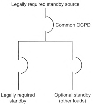
Informational Note Figure 700.3(F)
700.4 Capacity and Rating.
(A) Capacity.
An emergency system shall have adequate capacity in accordance with Parts I through IV of Article 220 or by another approved method. The system capacity shall be sufficient for the rapid load changes and transient power and energy requirements associated with any expected loads.
(B) Selective Load Management.
The alternate power source shall be permitted to supply emergency, legally required standby, and optional standby system loads where the source has adequate capacity or where load management (that includes automatic selective load pickup and load shedding) is provided as needed to ensure adequate power to the following in order of priority:
- Emergency circuits
- Legally required standby circuits
- Optional standby circuits
(C) Parallel Operation.
Parallel operation of the emergency source(s) shall consist of the sources specified in 700.4(C)(1) and (C)(2).
(1) Normal Source.
The emergency source shall be permitted to operate in parallel with the normal source in compliance with Part I or Part II of Article 705 where the capacity required to supply the emergency load is maintained at all times. Any operating condition that results in less than the required emergency source capacity shall initiate a system malfunction signal in accordance with 700.6(A).
Parallel operation shall be permitted for satisfying the test requirements of 700.3(B), provided all other conditions of 700.3 are met.
Informational Note: Peak load shaving is one application for parallel source operation.
(2) Emergency Source.
Emergency sources shall be permitted to operate in parallel where the necessary equipment to establish and maintain a synchronous condition is provided.
700.5 Transfer Equipment.
(A) General.
Transfer equipment shall be automatic, listed, and marked for emergency use. Transfer equipment shall be designed and installed to prevent the inadvertent interconnection of normal and emergency sources of supply in any operation of the transfer equipment. Transfer equipment and electric power production systems installed to permit operation in parallel with the normal source shall meet the requirements of Article 705. Meter-mounted transfer switches shall not be permitted for emergency system use.
(B) Bypass Isolation Transfer Switches.
Means shall be permitted to bypass and isolate the transfer equipment. Where bypass isolation transfer switches are used, inadvertent parallel operation shall be prevented.
(D) Redundant Transfer Equipment.
If emergency loads are supplied by a single feeder, the emergency power system shall include redundant transfer equipment or a bypass isolation transfer switch to facilitate maintenance as required in 700.3(C) without jeopardizing continuity of power. If the redundant transfer equipment or bypass isolation transfer switch is manual (or nonautomatic), then it shall be actively supervised by a qualified person when the primary (automatic) transfer equipment is disabled for maintenance or repair.
Exception: The requirement for redundancy with the transfer equipment shall not apply where any of the following conditions exist:
(1) All processes that rely on the emergency system source are capable of being disabled during maintenance or repair activities without jeopardizing the safety to human life.
(2) The building or structure is unoccupied and fire protection systems are fully functional and do not require an alternate power source.
(3) Other temporary means shall be permitted to be substituted for the emergency system.
(4) A written emergency plan that includes mitigation actions and responsibilities for qualified persons to address the recognized site hazards for the duration of the maintenance or repair activities shall be developed and implemented. The emergency plan shall be made available to the authority having jurisdiction.
(F) Documentation.
The short-circuit current rating of the transfer equipment, based on the specific overcurrent protective device type and settings protecting the transfer equipment, shall be field marked on the exterior of the transfer equipment.
700.6 Signals.
Audible, visual, and facility or network remote annunciation devices shall be provided, where applicable, for the purpose described in 700.6(A) through (D).
(A) Malfunction.
Malfunction signals indicate a malfunction of the emergency source.
(B) Carrying Load.
Load carrying signals indicate that the emergency source is carrying load.
(C) Storage Battery Charging Malfunction.
Storage battery charging malfunction signals indicate a charging malfunction on a battery required for source readiness, including starting the prime mover, is not functioning.
(D) Ground Fault.
Ground-fault signals indicate a ground fault in solidly grounded wye emergency systems of more than 150 volts to ground and circuit-protective devices rated 1000 amperes or more. The sensor for the ground-fault signal devices shall be located at, or ahead of, the main system disconnecting means for the emergency source, and the maximum setting of the signal devices shall be for a ground-fault current of 1200 amperes. Instructions on the course of action to be taken in the event of indicated ground fault shall be located at or near the sensor location.
For systems with multiple emergency sources connected to a paralleling bus, the ground fault sensor and the system bonding jumper shall be permitted to be at an alternative location.
700.7 Signs.
(A) Emergency Sources.
A sign shall be placed at the service-entrance equipment, indicating type and location of each on-site emergency power source.
Exception: A sign shall not be required for individual unit equipment as specified in 700.12(H).
(B) Grounding.
Where removal of a grounding or bonding connection in normal power source equipment interrupts the grounding electrode conductor connection to the alternate power source(s) grounded conductor, a warning sign shall be installed at the normal power source equipment stating:
WARNING
SHOCK HAZARD EXISTS IF GROUNDING ELECTRODE CONDUCTOR OR BONDING JUMPER CONNECTION IN THIS EQUIPMENT IS REMOVED WHILE ALTERNATE SOURCE(S) IS ENERGIZED.
SHOCK HAZARD EXISTS IF GROUNDING ELECTRODE CONDUCTOR OR BONDING JUMPER CONNECTION IN THIS EQUIPMENT IS REMOVED WHILE ALTERNATE SOURCE(S) IS ENERGIZED.
The warning sign(s) or label(s) shall comply with 110.21(B).
700.8 Surge Protection.
A listed SPD shall be installed in or on all emergency system switchgear, switchboards, and panelboards.
700.10 Wiring, Emergency System.
(A) Identification.
Emergency circuits shall be permanently marked so they will be readily identified as a component of an emergency circuit or system by the following methods:
- All boxes and enclosures (including transfer switches, generators, and power panels) for emergency circuits shall be permanently marked as a component of an emergency circuit or system.
- Where boxes or enclosures are not encountered, exposed cable or raceway systems shall be permanently marked to be identified as a component of an emergency circuit or system, at intervals not to exceed 7.6 m (25 ft).
Receptacles supplied from the emergency system shall have a distinctive color or marking on the receptacle cover plates or the receptacles.
(B) Wiring.
Wiring from an emergency source or emergency source distribution overcurrent protection to emergency loads shall be kept entirely independent of all other wiring and equipment unless otherwise permitted in the following: 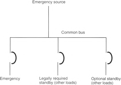
- Wiring from the normal power source located in transfer equipment enclosures
- Wiring supplied from two sources in exit or emergency luminaires
- Wiring from two sources in a listed load control relay supplying exit or emergency luminaires, or in a common junction box, attached to exit or emergency luminaires
- Wiring within a common junction box attached to unit equipment, containing only the branch circuit supplying the unit equipment and the emergency circuit supplied by the unit equipment
- Wiring within a traveling cable to an elevator
- Wiring from an emergency source to supply emergency and other (nonemergency) loads in accordance with the following:
- Separate vertical switchgear sections or separate vertical switchboard sections, with or without a common bus, or individual disconnects mounted in separate enclosures shall be used to separate emergency loads from all other loads.
- The common bus of separate sections of the switchgear, separate sections of the switchboard, or the individual enclosures shall be either of the following:
- Supplied by single or multiple feeders without overcurrent protection at the source
- Supplied by single or multiple feeders with overcurrent protection, provided that the overcurrent protection that is common to an emergency system and any nonemergency system(s) is selectively coordinated with the next downstream overcurrent protective device in the nonemergency system(s)Informational Note: See Informational Note Figure 700.10(B)(1) and Informational Note Figure 700.10(B)(2) for further information.
- Emergency circuits shall not originate from the same vertical switchgear section, vertical switchboard section, panelboard enclosure, or individual disconnect enclosure as other circuits.
- It shall be permissible to use single or multiple feeders to supply distribution equipment between an emergency source and the point where the emergency loads are separated from all other loads.
- At the emergency power source, such as a generator, multiple integral overcurrent protective devices shall each be permitted to supply a designated emergency or a designated nonemergency load, provided that there is complete separation between emergency and nonemergency loads beginning immediately after the overcurrent protective device line-side connections.
Wiring of two or more emergency circuits supplied from the same source shall be permitted in the same raceway, cable, box, or cabinet.
Informational Note Figure 700.10(B)(1) Single or Multiple Feeders Without Overcurrent Protection..
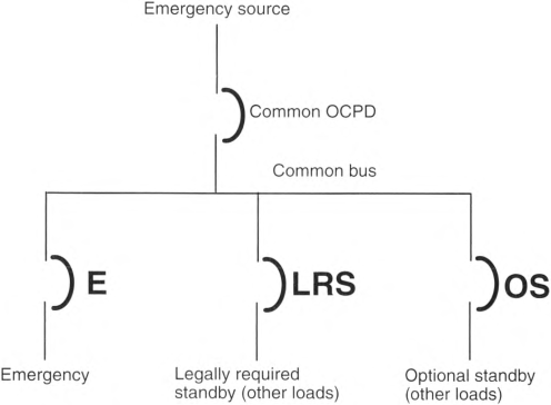
Informational Note Figure 700.10(B)(2) Single or Multiple Feeders with Overcurrent Protection.
(C) Wiring Design and Location.
Emergency wiring circuits shall be designed and located so as to minimize the hazards that might cause failure due to flooding, fire, icing, vandalism, and other adverse conditions.
(D) Fire Protection.
(1) Occupancies.
Emergency systems shall meet the additional requirements in 700.10(D)(2) through (D)(4) in the following occupancies:
- Assembly occupancies for not less than 1000 persons
- Buildings above 23 m (75 ft) in height
- Educational occupancies with more than 300 occupants
(2) Feeder-Circuit Wiring.
Feeder-circuit wiring shall meet one of the following conditions:
- The cable or raceway is installed in spaces or areas that are fully protected by an approved automatic fire protection system.
- The cable or raceway is protected by a listed electrical circuit protective system with a minimum 2-hour fire rating.Informational Note No. 1: See UL 1724, Fire Tests for Electrical Circuit Protection Systems, for one method of defining an electrical circuit protective system. The UL Guide Information for Electrical Circuit Integrity Systems (FHIT) contains information to identify the system and its installation limitations to maintain a minimum 2-hour fire-resistive rating and is available from the certification body.
- Informational Note No. 2: See UL 2196-2017, Standard for Fire Test for Circuit Integrity of Fire-Resistive Power, Instrumentation, Control and Data Cables, for one method of defining a fire-resistive cable system.
- The cable or raceway is protected by a listed fire-rated assembly that has a minimum fire rating of 2 hours and contains only emergency circuits.
- The cable or raceway is encased in a minimum of 50 mm (2 in.) of concrete.
(3) Feeder-Circuit Equipment.
Equipment for feeder circuits (including transfer switches, transformers, and panelboards) shall be located either in spaces fully protected by an approved automatic fire protection system or in spaces with a 2-hour fire resistance rating.
(4) Source Control Wiring.
Control conductors installed between the emergency power supply system/stored-energy power supply system (EPSS/SEPSS) and transfer equipment or control systems that initiate the operation of emergency sources or initiate the automatic connection to emergency loads shall be kept entirely independent of all other wiring and shall meet the conditions of 700.10(D)(2). The integrity of source control wiring shall be monitored for broken, disconnected, or shorted wires. Loss of integrity shall result in the following actions:
- Generators. Shall start the generator(s).
- All other sources. Shall be considered a system malfunction and initiate the designated signal(s) in 700.6(A).
700.11 Wiring, Class-2-Powered Emergency Lighting Systems.
(B) Identification.
Emergency circuits shall be permanently marked so they will be readily identified as a component of an emergency circuit or system by the following methods:
- All boxes and enclosures for Class 2 emergency circuits shall be permanently marked as a component of an emergency circuit or system.
- Exposed cable, cable tray, or raceway systems shall be permanently marked to be identified as a component of an emergency circuit or system, within 900 mm (3 ft) of each connector and at intervals not to exceed 7.6 m (25 ft).
(C) Separation of Circuits.
Class 2 emergency circuits shall be wired in a listed, jacketed cable or with one of the wiring methods of Chapter 3. If installed alongside nonemergency Class 2 circuits that are bundled, Class 2 emergency circuits shall be bundled separately. If installed alongside nonemergency Class 2 circuits that are not bundled, Class 2 emergency circuits shall be separated by a nonconductive sleeve or nonconductive barrier from all other Class 2 circuits. Separation from other circuits shall comply with 725.136.
(D) Protection.
Wiring shall comply with the requirements of 300.4 and be installed in a raceway, armored or metal-clad cable, or cable tray.
Exception Exception No. 1: Section 700.11(D) shall not apply to wiring that does not exceed 1.83 m (6 ft) in length and that terminates at an emergency luminaire or an emergency lighting control device.
Exception Exception No. 2: Section 700.11(D) shall not apply to locked rooms or locked enclosures that are accessible only to qualified persons.
Informational Note: Locked rooms accessible only to qualified persons include locked telecommunications rooms, locked electrical equipment rooms, or other access-controlled areas.
700.12 General Requirements.
Current supply shall be such that, in the event of failure of the normal supply to, or within, the building or group of buildings concerned, emergency lighting, emergency power, or both shall be available within the time required for the application but not to exceed 10 seconds. The supply system for emergency purposes, in addition to the normal services to the building and meeting the general requirements of this section, shall be one or more of the types of systems described in 700.12(C) through (H). Unit equipment in accordance with 700.12(H) shall satisfy the applicable requirements of this article.
(A) Power Source Considerations.
In selecting an emergency source of power, consideration shall be given to the occupancy and the type of service to be rendered, whether of minimum duration, as for evacuation of a theater, or longer duration, as for supplying emergency power and lighting due to an indefinite period of current failure from trouble either inside or outside the building.
(B) Equipment Design and Location.
Equipment shall be designed and located so as to minimize the hazards that might cause complete failure due to flooding, fires, icing, and vandalism.
Equipment for sources of power as described in 700.12(C) through (H) shall be installed either in spaces fully protected by approved automatic fire protection systems or in spaces with a 2-hour fire rating where located within the following:
- Assembly occupancies for more than 1000 persons
- Buildings above 23 m (75 ft) in height
- Educational occupancies with more than 300 occupants
Informational Note No. 1: See NFPA 101-2021, Life Safety Code, Section 6.1, for information on occupancy classifications.
Informational Note No. 2: See IEEE 3006.5-2014, Recommended Practice for the Use of Probability Methods for Conducting a Reliability Analysis of Industrial and Commercial Power Systems, for information regarding power system reliability.
(C) Supply Duration.
The emergency power source shall be of suitable rating and capacity to supply and maintain the total load for the duration determined by the system design. In no case shall the duration be less than 2 hours of system operation unless used for emergency illumination in 700.12(C)(4) or unit equipment in 700.12(H). Additionally, the power source shall comply with 700.12(C)(1) through (C)(5) as applicable.
Informational Note: See NFPA 110-2022, Standard for Emergency and Standby Power Systems, for information on classification of emergency power supply systems (EPSS).
(1) On-Site Fuel Supply.
An on-site fuel supply shall be provided, sufficient for not less than 2 hours operation of the system.
(2) Fuel Transfer Pumps.
Where power is needed for the operation of the fuel transfer pumps to deliver fuel to the source, these pumps shall be connected to the emergency power system.
(3) Public Gas System, Municipal Water Supply.
Sources shall not be solely dependent on a public utility gas system for their fuel supply or municipal water supply for their cooling systems.
Exception: Where approved by the authority having jurisdiction, the use of other than on-site fuels shall be permitted where there is a low probability of a simultaneous failure of both the off-site fuel delivery system and power from the outside electrical utility company. Where the public gas system is approved, the requirements of 700.12(C)(1) shall not apply.
(4) Storage Batteries and UPS.
Storage batteries and UPS used to supply emergency illumination shall be of suitable rating and capacity to supply and maintain the total load for a minimum period of 11/2 hours, without the voltage applied to the load falling below 871/2 percent of nominal voltage. Automotive-type batteries shall not be used. An automatic battery charging means shall be provided.
(5) Automatic Fuel Transfer.
Where dual fuel sources are used, means shall be provided for automatically transferring from one fuel source to another.
(D) Generator Set.
(1) Prime Mover-Driven.
For a generator set driven by a prime mover approved by the authority having jurisdiction and sized in accordance with 700.4, means shall be provided for automatically starting the prime mover on failure of the normal power source and for automatic transfer and operation of all required electrical circuits. A time-delay feature shall be provided to avoid retransfer in case of short-time reestablishment of the normal source.
(2) Battery Power and Dampers.
Where a storage battery is used for control or signal power or as the means of starting the prime mover, it shall be suitable for the purpose and shall be equipped with an automatic charging means independent of the generator set. Where the battery charger is required for the operation of the generator set, it shall be connected to the emergency system. Where power is required for the operation of dampers used to ventilate the generator set, the dampers shall be connected to the emergency system.
(3) Auxiliary Power Supply.
Generator sets that require more than 10 seconds to develop power shall be permitted if an auxiliary power supply energizes the emergency system until the generator can pick up the load.
(4) Outdoor Generator Sets.
Where an outdoor-housed generator set is equipped with a readily accessible disconnecting means in accordance with 445.18, and the disconnecting means is located within sight of the building or structure supplied, an additional disconnecting means shall not be required where ungrounded conductors serve or pass through the building or structure. Where the generator supply conductors terminate at a disconnecting means in or on a building or structure, the disconnecting means shall meet the requirements of 225.36.
Exception: For installations under single management, where conditions of maintenance and supervision ensure that only qualified persons will monitor and service the installation and where documented safe switching procedures are established and maintained for disconnection, the generator set disconnecting means shall not be required to be located within sight of the building or structure served.
(E) Stored-Energy Power Supply Systems (SEPSS).
(1) Types.
Systems shall consist of one or more of the following system types:
- Informational Note: See UL 1778, Uninterruptible Power Systems, for further information.
- Fuel cell system
- Energy storage system (ESS)
- Storage battery
- Other approved equivalent stored energy sources that comply with 700.12
(2) Fire Protection, Suppression, Ventilation, and Separation.
The systems in 700.12(E)(1) shall be installed with the fire protection, suppression, ventilation, and separation requirements specified in the manufacturer's instructions or equipment listing.
Informational Note: See NFPA 853-2020, Standard for the Installation of Stationary Fuel Cell Power Systems, and NFPA 855-2020, Standard for the Installation of Stationary Energy Storage Systems, for additional information on fire protection installation requirements.
(F) Separate Service.
Where approved by the authority having jurisdiction as suitable for use as an emergency source of power, an additional service shall be permitted. This service shall be in accordance with the applicable provisions of Article 230 and the following additional requirements:
- Separate overhead service conductors, service drops, underground service conductors, or service laterals shall be installed.
- The service conductors for the separate service shall be installed sufficiently remote electrically and physically from any other service conductors to minimize the possibility of simultaneous interruption of supply.
(G) Microgrid Systems.
On-site sources, designated as emergency sources, shall be permitted to be connected to a microgrid system.
The system shall isolate the emergency system from all nonemergency loads when the normal electric supply is interrupted or shall meet the requirements of 700.4(B). Interruption or partial or complete failure of the normal or nonemergency source(s) shall not impact the availability, capacity, and duration provided by the designated emergency sources.
The designated stored-energy electrical emergency power source(s) of a microgrid system shall be permitted to remain interconnected to any available power production source during operation of the emergency source(s) where the lack of, or failure of, the interconnected power production source(s), or related controls, does not impact system operation. Interconnected power production sources, other than the designated stored emergency power source(s), shall not be required to meet the requirements of this article.
(H) Battery-Equipped Emergency Luminaires.
(1) Listing.
All battery-equipped emergency luminaires shall be listed.
Informational Note No. 1: See ANSI/UL 924, Emergency Lighting and Power Equipment, for the requirements covering battery-equipped emergency luminaires and emergency battery packs. A listed emergency battery pack installed in a listed luminaire will provide similar functionality as a listed battery-equipped emergency luminaire.
(2) Installation.
Battery-equipped emergency luminaires shall be installed in accordance with the following:
- Battery-equipped emergency luminaires shall be permanently fixed in place (i.e., not portable).
- Wiring to each luminaire shall be installed in accordance with the requirements of any of the wiring methods in Chapter 3 unless otherwise specified in Part II, IV, or V of this article. Flexible cord-and-plug connection shall be permitted for unit equipment, provided that the cord does not exceed 900 mm (3 ft) in length. Flexible cord, with or without a plug, shall also be permitted for battery-equipped emergency luminaires installed in accordance with 410.62(C)(1).
- The branch circuit feeding the battery-equipped emergency luminaire shall be one of the following:
- The same branch circuit as that serving the normal lighting in the area and connected ahead of any local switches.
- The same or a different branch circuit as that serving the normal lighting in the area if that circuit is equipped with means to monitor the status of that area's normal lighting branch circuit ahead of any local switches.
- A separate branch circuit originating from the same panelboard as one or more normal lighting circuits. This separate branch circuit disconnecting means shall be provided with a lock-on feature.
- The branch circuit that feeds battery-equipped emergency luminaires shall be clearly identified at the distribution panel.
- Emergency luminaires that obtain power from a battery-equipped emergency luminaire shall be wired to the battery-equipped emergency luminaires as required in Part II, IV, or V of this article.
- Remote luminaires providing lighting for the exterior of an exit door shall be permitted to be supplied by the battery-equipped emergency luminaire serving the area immediately inside the exit door.
700.15 Loads on Emergency Branch Circuits.
No appliances and no lamps, other than those specified as required for emergency use, shall be supplied by emergency lighting circuits.
700.16 Emergency Illumination.
(A) General.
Emergency illumination shall include means of egress lighting, illuminated exit signs, and all other luminaires specified as necessary to provide required illumination.
(B) System Reliability.
Emergency lighting systems shall be designed and installed so that the failure of any illumination source cannot leave in total darkness any space that requires emergency illumination. Emergency lighting control devices in the emergency lighting system shall be listed for use in emergency systems. Listed unit equipment in accordance with 700.12(H) shall be considered as meeting the provisions of this section.
(C) Discharge Lighting.
Where high-intensity discharge lighting such as high- and low-pressure sodium, mercury vapor, and metal halide is used as the sole source of normal illumination, the emergency lighting system shall be required to operate until normal illumination has been restored.
(D) Disconnecting Means.
Where an emergency system is installed, emergency illumination shall be provided in the area of the disconnecting means required by 225.31 and 230.70, as applicable, where the disconnecting means are installed indoors.
Exception: Alternative means that ensure that the emergency lighting illumination level is maintained shall be permitted.
700.17 Branch Circuits for Emergency Lighting.
Branch circuits that supply emergency lighting shall be installed to provide service from a source complying with 700.12 when the normal supply for lighting is interrupted. Such installations shall provide either of the following:
- An emergency lighting supply, independent of the normal lighting supply, with provisions for automatically transferring the emergency lights upon the event of failure of the normal lighting supply.
- Two or more branch circuits supplied from separate and complete systems with independent power sources. One of the two power sources and systems shall be part of the emergency system, and the other shall be permitted to be part of the normal power source and system. Each system shall provide sufficient power for emergency lighting purposes.
Unless both systems are used for regular lighting purposes and both are kept lighted, means shall be provided for automatically energizing either system upon failure of the other. Either system or both systems shall be permitted to be a part of the general lighting of the protected occupancy if circuits supplying lights for emergency illumination are installed in accordance with other sections of this article.
700.18 Circuits for Emergency Power.
For branch circuits that supply equipment classed as emergency, there shall be an emergency system supply source to which the load will be transferred automatically upon the failure of the normal supply.
700.19 Multiwire Branch Circuits.
The branch circuit serving emergency lighting and power circuits shall not be part of a multiwire branch circuit.
700.20 Switch Requirements.
The switch or switches installed in emergency lighting circuits shall be arranged so that only authorized persons have control of emergency lighting.
Exception No. I: Where two or more single-throw switches are connected in parallel to control a single circuit, at least one of these switches shall be accessible only to authorized persons.
Exception No. 2: Additional switches that act only to put emergency lights into operation but not disconnect them shall be permissible.
Switches connected in series or 3- and 4-way switches shall not be used.
700.21 Switch Location.
All manual switches for controlling emergency circuits shall be in locations convenient to authorized persons responsible for their actuation. In facilities covered by Articles 518 and 520, a switch for controlling emergency lighting systems shall be located in the lobby or at a place conveniently accessible thereto.
In no case shall a control switch for emergency lighting be placed in a motion-picture projection booth or on a stage or platform.
Exception: Where multiple switches are provided, one such switch shall be permitted in such locations where arranged so that it can only energize the circuit but cannot de-energize the circuit.
700.23 Dimmer and Relay Systems.
A dimmer or relay system containing more than one dimmer or relay and listed for use in emergency systems shall be permitted to be used as a control device for energizing emergency lighting circuits. Upon failure of normal power, the dimmer or relay system shall be permitted to selectively energize only those branch circuits required to provide minimum emergency illumination using a control bypass function. Where the dimmer or relay system is fed by a normal/emergency power source from an upstream transfer switch, normal power sensing for this function shall be permitted to be from a normal-only power source upstream of the transfer switch. All branch circuits supplied by the dimmer or relay system cabinet shall comply with the wiring methods of Part II of Article 700.
700.24 Directly Controlled Emergency Luminaires.
Where emergency illumination is provided by one or more directly controlled emergency luminaires that, upon loss of normal power, respond to an external control input to establish the required emergency illumination level, such directly controlled emergency luminaries shall be listed for use in emergency systems. Luminaires that are energized to the required emergency illumination level by disconnection of their control input by a listed emergency lighting control device shall not be required to be listed for use in emergency systems.
700.25 Branch Circuit Emergency Lighting Transfer Switch.
Emergency lighting loads supplied by branch circuits rated at not greater than 20 amperes shall be permitted to be transferred from the normal branch circuit to an emergency branch circuit using a listed branch circuit emergency lighting transfer switch. The mechanically held requirement of 700.5(C) shall not apply to listed branch circuit emergency lighting transfer switches.
700.30 Accessibility.
The branch-circuit overcurrent devices in emergency circuits shall be accessible to authorized persons only.
700.31 Ground-Fault Protection of Equipment.
The alternate source for emergency systems shall not be required to provide ground-fault protection of equipment with automatic disconnecting means. Ground-fault indication at the emergency source shall be provided in accordance with 700.6(D) if ground-fault protection of equipment with automatic disconnecting means is not provided.
700.32 Selective Coordination.
(A) General.
Emergency system(s) overcurrent protective devices (OCPDs) shall be selectively coordinated with all supply-side and load-side OCPDs.
Selective coordination shall be selected by a licensed professional engineer or other qualified persons engaged primarily in the design, installation, or maintenance of electrical systems. The selection shall be documented and made available to those authorized to design, install, inspect, maintain, and operate the system.
(B) Replacements.
Where emergency system(s) OCPDs are replaced, they shall be reevaluated to ensure selective coordination is maintained with all supply-side and load-side OCPDs.
(C) Modifications.
If modifications, additions, or deletions to the emergency system(s) occur, selective coordination of the emergency system(s) OCPDs with all supply-side and load-side OCPDs shall be reevaluated.
Exception: Selective coordination shall not be required between two overcurrent devices located in series if no loads are connected in parallel with the downstream device.
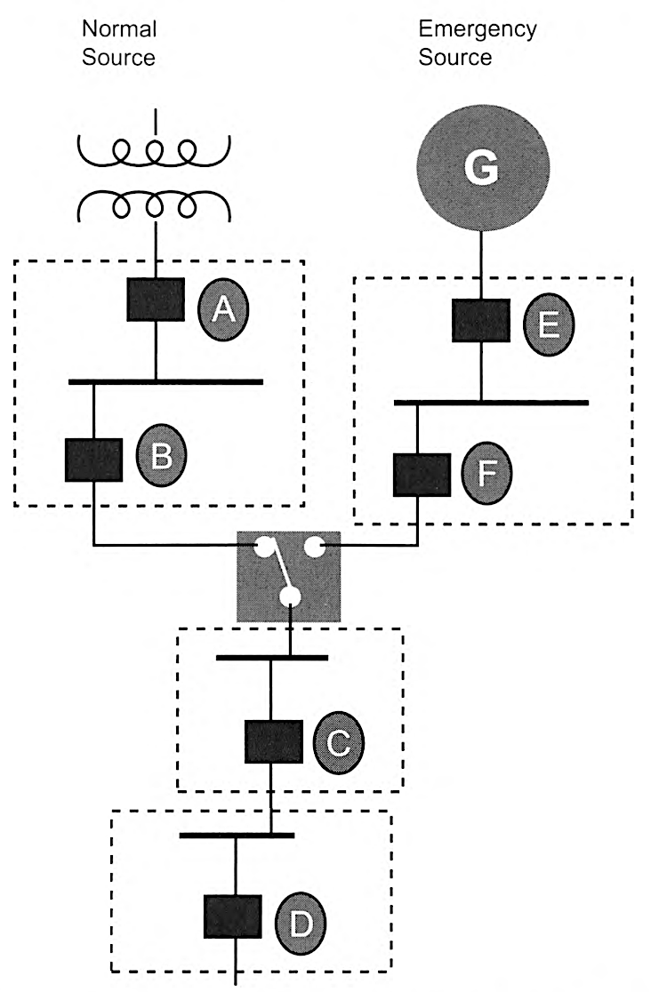
Informational Note: See Informational Note Figure 700.32(C) for an example of how emergency system OCPDs selectively coordinate with all supply-side OCPDs.
OCPD D selectively coordinates with OCPDs C, F, E, B, and A.
OCPD C selectively coordinates with OCPDs F, E, B, and A.
OCPD F selectively coordinates with OCPD E.
OCPD B is not required to selectively coordinate with OCPD A because OCPD B is not an emergency system OCPD.
Informational Note Figure 700.32(C) Emergency System Selective Coordination.
Article 701
Legally Required Standby Systems
701.1 Scope.
This article applies to the electrical safety of the installation, operation, and maintenance of legally required standby systems consisting of circuits and equipment intended to supply, distribute, and control electricity to required facilities for illumination or power, or both, when the normal electrical supply or system is interrupted.
The systems covered by this article consist only of those that are permanently installed in their entirety, including the power source.
Informational Note No. 1: See NFPA 99-2018, Health Care Facilities Code, for further information.
Informational Note No. 2: See NFPA 110-2019, Standard for Emergency and Standby Power Systems, for further information regarding performance of emergency and standby power systems.
Informational Note No. 3: See ANSI/IEEE 446-1995, Recommended Practice for Emergency and Standby Power Systems for Industrial and Commercial Applications, for further information.
Informational Note No. 4: Legally required standby systems are typically installed to serve loads, such as heating and refrigeration systems, communications systems, ventilation and smoke removal systems, sewage disposal systems, lighting systems, and industrial processes that, when stopped during any interruption of the normal electrical supply, could create hazards or hamper rescue or firefighting operations.
Informational Note No. 5: Legally required standby systems are considered level one systems when failure to perform could result in loss of human life or serious injuries and level two systems when failure of legally required standby systems to perform is less critical to human life and safety when applying NFPA 110-2019, Standard for Emergency Standby Power Systems.
701.3 Commissioning and Maintenance.
(A) Commissioning Witness Test.
The authority having jurisdiction shall conduct or witness the commissioning of the complete system upon installation.
(B) Tested Periodically.
Systems shall be tested periodically on a schedule and in a manner approved by the authority having jurisdiction to ensure the systems are maintained in proper operating condition.
(C) Maintenance.
Legally required standby system equipment shall be maintained in accordance with manufacturer instructions and industry standards.
(D) Written Record.
A written record shall be kept on such tests and maintenance.
(E) Testing Under Load.
Means for testing legally required standby systems under load shall be provided.
Informational Note: See NFPA 110-2019, Standard for Emergency and Standby Power Systems, for information on testing and maintenance of emergency power supply systems (EPSSs).
701.4 Capacity and Rating.
(A) Rating.
Legally required standby system equipment shall be suitable for the available fault current at its terminals.
(B) Capacity.
A legally required standby system shall have adequate capacity in accordance with Parts I through IV of Article 220 or by another approved method. The system capacity shall be sufficient for the rapid load changes and transient power and energy requirements associated with any expected loads.
(C) Load Management.
The alternate power source shall be permitted to supply legally required standby and optional standby system loads where the alternate source has adequate capacity or where load management (that includes automatic selective load pickup and load shedding) is provided that will ensure adequate power to the legally required standby circuits.
(D) Parallel Operation.
Parallel operation shall comply with Part I or Part II of Article 705 where the legally required source capacity required to supply the legally required load is maintained at all times. Parallel operation of the legally required source(s) shall consist of the sources specified in 701.4(D)(1) and (D)(2).
(1) Normal Source.
The alternate power source shall be permitted to operate in parallel with the normal source in compliance with Part I or Part II of Article 705 where the capacity required to supply the legally required standby load is maintained at all times. Any operating condition that results in less than the required source capacity shall initiate a legally required standby source malfunction signal in 701.6(A).
Parallel operation shall be permitted for satisfying the test requirements of 701.3(B), provided all other conditions of 701.3 are met.
Informational Note: Peak load shaving is one application for parallel source operation.
(2) Alternate Source.
Legally required standby sources shall be permitted to operate in parallel where the necessary equipment to establish and maintain a synchronous condition is provided.
701.5 Transfer Equipment.
(A) General.
Transfer equipment shall be automatic, listed, and marked for emergency system or legally required standby use. Transfer equipment shall be designed and installed to prevent the inadvertent interconnection of normal and alternate sources of supply in any operation of the transfer equipment. Transfer equipment and electric power production systems installed to permit operation in parallel with the normal source shall meet the requirements of Article 705. Meter-mounted transfer switches shall not be permitted for legally required system use.
(B) Bypass Isolation Switches.
Means to bypass and isolate the transfer switch equipment shall be permitted. Where bypass isolation switches are used, inadvertent parallel operation shall be avoided.
(D) Documentation.
The short-circuit current rating of the transfer equipment, based on the specific overcurrent protective device type and settings protecting the transfer equipment, shall be field marked on the exterior of the transfer equipment.
701.6 Signals.
Audible and visual signal devices shall be provided, where practicable, for the purposes described in 701.6(A), (B), (C), and (D).
(A) Malfunction.
Malfunction signals indicate a malfunction of the standby source.
(B) Carrying Load.
Load carrying signals indicate that the standby source is carrying load.
(C) Battery Charging Malfunction.
Battery charging malfunction signals indicate charging malfunction on a battery required for source readiness, including the prime mover starting battery.
Informational Note: See NFPA 110-2019, Standard for Emergency and Standby Power Systems, for signals for generator sets.
(D) Ground Fault.
Ground-fault signals indicate a ground fault in solidly grounded wye, legally required standby systems of more than 150 volts to ground and circuit-protective devices rated 1000 amperes or more. The sensor for the ground-fault signal devices shall be located at, or ahead of, the main system disconnecting means for the legally required standby source, and the maximum setting of the signal devices shall be for a ground-fault current of 1200 amperes. Instructions on the course of action to be taken in the event of an indicated ground fault shall be located at or near the sensor location.
For systems with multiple emergency sources connected to a paralleling bus, the ground-fault sensor shall be permitted at an alternate location.
Informational Note: See NFPA 110-2019, Standard for Emergency and Standby Power Systems, for signals for generator sets.
701.7 Signs.
(A) Mandated Standby.
A sign shall be placed at the service entrance indicating type and location of each on-site legally required standby power source.
Exception: A sign shall not be required for individual unit equipment as specified in 701.12(1).
(B) Grounding.
Where removal of a grounding or bonding connection in normal power source equipment interrupts the grounding electrode conductor connection to the alternate power source(s) grounded conductor, a warning sign shall be installed at the normal power source equipment stating:
WARNING
SHOCK HAZARD EXISTS IF GROUNDING ELECTRODE
CONDUCTOR OR BONDING JUMPER CONNECTION IN
THIS EQUIPMENT IS REMOVED WHILE ALTERNATE
SOURCE(S) IS ENERGIZED..
The warning sign(s) or label(s) shall comply with 110.21(B).
701.10 Wiring Legally Required Standby Systems.
(B) Wiring.
Wiring from a legally required source to supply legally required and other (nonlegally required) loads shall be in accordance with the following: 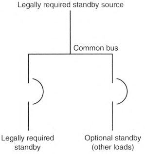
- The common bus of switchgear, sections of a switchboard, or individual enclosures shall be either of the following:
- Supplied by single or multiple feeders without overcurrent protection at the source
- Supplied by single or multiple feeders with overcurrent protection, provided that the overcurrent protection that is common to a legally required system and any nonlegally required system(s) is selectively coordinated with the next downstream overcurrent protective device in the nonlegally required system(s)
Informational Note: See Informational Note Figure 701.10(B)(1) and Informational Note Figure 701.10(B)(2) for further information.
Informational Note: See Informational Note Figure 701.10(B)(1) Single or Multiple Feeders Without Overcurrent Protection..
Informational Note Figure 701.10(B)(2) Single or Multiple Feeders with Overcurrent Protection.
701.12 General Requirements.
Current supply shall be such that, in the event of failure of the normal supply to, or within, the building or group of buildings concerned, legally required standby power will be available within the time required for the application but not to exceed 60 seconds. The supply system for legally required standby purposes, in addition to the normal services to the building, shall be permitted to comprise one or more of the types of systems described in 701.12(A) through (I). Unit equipment in accordance with 701.12(1) shall satisfy the applicable requirements of this article.
(A) Power Source Considerations.
In selecting a legally required standby source of power, consideration shall be given to the type of service to be rendered, whether of short-time duration or long duration.
(B) Equipment Design and Location.
Consideration shall be given to the location or design, or both, of all equipment to minimize the hazards that might cause complete failure due to floods, fires, icing, and vandalism.
Informational Note: See ANSI/IEEE 493-2007, Recommended Practice for the Design of Reliable Industrial and Commercial Power Systems, for further information.
(C) Supply Duration.
The alternate power source shall be of suitable rating and capacity to supply and maintain the total load for the duration determined by the system design. In no case shall the duration be less than 2 hours of system operation. Additionally, the power source shall comply with 701.12(C)(1) through (C)(5) as applicable.
Informational Note: See NFPA 110-2022, Standard for Emergency and Standby Power Systems, for information on classification of emergency power supply systems (EPSS).
(1) On-Site Fuel Supply.
An on-site fuel supply shall be provided, sufficient for not less than 2 hours operation of the system.
(2) Fuel Transfer Pumps.
Where power is needed for the operation of the fuel transfer pumps to deliver fuel to the source, these pumps shall be connected to the legally required standby power system.
(3) Public Gas System, Municipal Water Supply.
Sources shall not be solely dependent on a public utility gas system for their fuel supply or on a municipal water supply for their cooling systems.
Exception: Where approved by the authority having jurisdiction, the use of other than on-site fuels shall be permitted where there is a low probability of a simultaneous failure of both the off-site fuel delivery system and power from the outside electrical utility company. Where a public gas system is approved, the requirements of 701.12(C)(1) shall not apply.
(4) Storage Batteries and UPS.
Storage batteries and UPS used to supply standby illumination shall be of suitable rating and capacity to supply and maintain the total load for a minimum period of 11/2 hours, without the voltage applied to the load falling below 871/2 percent of nominal voltage. Automotive-type batteries shall not be used. An automatic battery charging means shall be provided.
(5) Automatic Fuel Source Transfer.
Where dual fuel sources are used, means shall be provided for automatically transferring from one fuel source to another.
(D) Generator Set.
(1) Prime Mover-Driven.
For a generator set driven by a prime mover approved by the authority having jurisdiction and sized in accordance with 701.4, means shall be provided for automatically starting the prime mover upon failure of the normal power source and for automatic transfer and operation of all required electrical circuits. A time-delay feature permitting a 15-minute setting shall be provided to avoid retransfer in case of short-time reestablishment of the normal source.
(2) Battery Power.
Where a storage battery is used for control or signal power or as the means of starting the prime mover, it shall be suitable for the purpose and shall be equipped with an automatic charging means independent of the generator set.
(3) Outdoor Generator Sets.
If an outdoor-housed generator set is equipped with a readily accessible disconnecting means in accordance with 445.18, and the disconnecting means is located within sight of the building or structure supplied, an additional disconnecting means shall not be required where ungrounded conductors serve or pass through the building or structure. Where the generator supply conductors terminate at a disconnecting means in or on a building or structure, the disconnecting means shall meet the requirements of 225.36.
(E) Stored-Energy Power Supply Systems (SEPSS).
(1) Types.
Systems shall consist of one or more of the following system types:
- Informational Note: See UL 1778, Uninterruptable Power Systems, and UL 924, Emergency Lighting and Power Equipment, for further information.
- Fuel cell system
- Energy storage system (ESS)
- Storage battery
- Other approved equivalent stored energy sources that comply with 701.12
(2) Fire Protection, Suppression, Ventilation, and Separation.
The systems in 701.12(E)(1) shall be installed with the fire protection, suppression, ventilation, and separation requirements specified in the manufacturer's instructions or equipment listing.
Informational Note: See NFPA 853-2020, Standard for the Installation of Stationary Fuel Cell Power Systems, and NFPA 855-2020, Standard for the Installation of Stationary Energy Storage Systems, for additional information on fire protection installation requirements.
(F) Separate Service.
Where approved, by the authority having jurisdiction as suitable for use as a legally required source of power, an additional service shall be permitted. This service shall be in accordance with Article 230 and the following additional requirements:
- Separate overhead service conductors, service drops, underground service conductors, or service laterals shall be installed.
- The service conductors for the separate service shall be installed sufficiently remote electrically and physically from any other service conductors to minimize the possibility of simultaneous interruption of supply.
(G) Connection Ahead of Service Disconnecting Means.
Where approved by the authority having jurisdiction, connections located ahead of and not within the same cabinet, enclosure, vertical switchgear section, or vertical switchboard section as the service disconnecting means shall be permitted. The legally required standby service shall be sufficiently separated from the normal main service disconnecting means to minimize simultaneous interruption of supply through an occurrence within the building or groups of buildings served.
Informational Note: See 230.82 for equipment permitted on the supply side of a service disconnecting means.
(H) Microgrid Systems.
On-site sources, designated as legally required standby sources, shall be permitted to be connected to a microgrid system.
The system shall isolate the legally required standby system from all nonlegally required loads when the normal electric supply is interrupted or shall meet the requirements of 701.4(C). Interruption or partial or complete failure of the normal source(s) shall not impact the availability, capacity, and duration provided by the designated legally required standby sources.
The designated stored-energy legally required standby power source(s) of a microgrid system shall be permitted to remain interconnected to any available power production source during operation of the legally required standby source(s) where the lack of, or failure of, the interconnected power production source(s), or related controls, does not impact system operation. Interconnected power production sources, other than the designated SEPSS, shall not be required to meet the requirements of this article.
(I) Battery-Equipped Emergency Luminaires, Used for Legally Required Standby Systems.
Battery-equipped emergency luminaires used for legally required standby systems shall comply with 700.12(H).
701.30 Accessibility.
The branch-circuit overcurrent devices in legally required standby circuits shall be accessible to authorized persons only.
701.31 Ground-Fault Protection of Equipment.
The alternate source for legally required standby systems shall not be required to provide ground-fault protection of equipment with automatic disconnecting means. Ground-fault indication at the legally required standby source shall be provided in accordance with 701.6(D) if ground-fault protection of equipment with automatic disconnecting means is not provided.
701.32 Selective Coordination.
(A) General.
Legally required standby system(s) overcurrent protective devices (OCPDs shall be selectively coordinated with all supply-side and load-side OCPDs.
Selective coordination shall be selected by a licensed professional engineer or other qualified persons engaged primarily in the design, installation, or maintenance of electrical systems. The selection shall be documented and made available to those authorized to design, install, inspect, maintain, and operate the system.
(B) Replacements.
Where legally required standby OCPDs are replaced, they shall be reevaluated to ensure selective coordination is maintained with all supply-side and load-side OCPDs.
(C) Modifications.
If modifications, additions, or deletions to the legally required standby system(s) occur, selective coordination of the legally required system(s) OCPDs with all supply-side and load-side OCPDs shall be reevaluated. 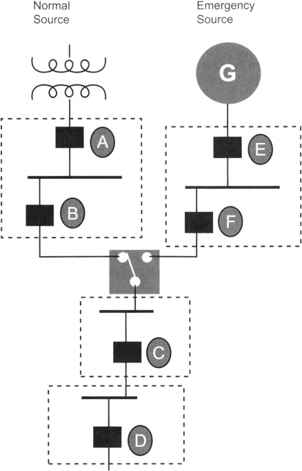
Exception: Selective coordination shall not be required between two overcurrent devices located in series if no loads are connected in parallel with the downstream device.
Informational Note: See Informational Note Figure 701.32(C) for an example of how legally required standby system OCPDs selectively coordinate with all supply-side OCPDs.
OCPD D selectively coordinates with OCPDs C, F, E, B, and A.
OCPD C selectively coordinates with OCPDs F, E, B, and A.
OCPD F selectively coordinates with OCPD E.
OCPD B is not required to selectively coordinate with OCPD A because OCPD B is not a legally required standby system OCPD.
Informational Note Figure 701.32(C) Legally Required Standby System Selective Coordination.
Article 702
Optional Standby Systems
702.1 Scope.
This article applies to the installation and operation of optional standby systems.
The systems covered by this article consist of those that are permanently installed in their entirety, including prime movers, and those that are arranged for a connection to a premises wiring system from a portable alternate power supply.
Informational Note: Optional standby systems are typically installed to provide an alternate source of electric power for such facilities as industrial and commercial buildings, farms, and residences and to serve loads such as heating and refrigeration systems, data processing and communications systems, and industrial processes that, when stopped during any power outage, could cause discomfort, serious interruption of the process, damage to the product or process, or the like.
702.4 Capacity and Rating.
(A) System Capacity.
(1) Manual and Nonautomatic Load Connection.
If the connection of load is manual or nonautomatic, an optional standby system shall have adequate capacity and rating for the supply of all equipment intended to be operated at one time. The user of the optional standby system shall be permitted to select the load connected to the system.
Informational Note: Manual and nonautomatic transfer equipment require human intervention.
(2) Automatic Load Connection.
If the connection of load is automatic, an optional standby system shall comply with 702.4(A)(2)(a) or (A)(2)(b) in accordance with Parts I through IV of Article 220 or by another approved method.
- Full Load. The standby source shall be capable of supplying the full load that is automatically connected.
- Energy Management System (EMS). Where a system is employed in accordance with 750.30 that will automatically manage the connected load, the standby source shall have a capacity sufficient to supply the maximum load that will be connected by the EMS.
702.5 Interconnection or Transfer Equipment.
(A) General.
Interconnection or transfer equipment shall be required for all standby systems subject to the requirements of this article. Equipment shall be suitable for the intended use and shall be listed, designed, and installed so as to prevent the inadvertent interconnection of all sources of supply in any operation of the equipment.
Exception: Temporary connection of a portable generator without transfer equipment shall be permitted where conditions of maintenance and supervision ensure that only qualified persons service the installation and where the normal supply is physically isolated by a lockable disconnecting means or by disconnection of the normal supply conductors.
(B) Meter-Mounted Transfer Switches.
Transfer switches installed between the utility meter and the meter enclosure shall be listed meter-mounted transfer switches and shall be approved.
Informational Note No. 1: See UL 1008M, Transfer Stritch Equipment, Meter Mounted, for more information.
Informational Note No. 2: Manual and nonautomatic transfer equipment use human intervention.
(C) Documentation.
In other than dwelling units, the short-circuit current rating of the transfer equipment, based on the specific overcurrent protective device type and settings protecting the transfer equipment, shall be field marked on the exterior of the transfer equipment.
(D) Parallel Installation.
Systems installed to permit operation in parallel with the normal source shall also meet Part I or Part II of Article 705.
702.6 Signals.
Audible and visual signal devices shall be provided, where practicable, for the following purposes specified in 702.6(A) and (B).
(A) Malfunction.
To indicate malfunction of the optional standby source.
(B) Carrying Load.
To indicate that the optional standby source is carrying load.
Exception: Signals shall not be required for portable standby power sources.
702.7 Signs.
(A) Standby.
A sign shall be placed at the service equipment for other than one- and two-family dwellings that indicates the type and location of each on-site optional standby power source. For one- and two-family dwelling units, a sign shall be placed at the disconnecting means required in 230.85 that indicates the location of each permanently installed on-site optional standby power source disconnect or means to shut down the prime mover as required in 445.19(C).
(B) Grounding.
Where removal of a grounding or bonding connection in normal power source equipment interrupts the grounding electrode conductor connection to the alternate power source(s) grounded conductor, a warning sign shall be installed at the normal power source equipment stating:
WARNING:
SHOCK HAZARD EXISTS IF GROUNDING ELECTRODE
CONDUCTOR OR BONDING JUMPER CONNECTION IN
THIS EQUIPMENT IS REMOVED WHILE ALTERNATE
SOURCE(S) IS ENERGIZED..
The warning sign(s) or label(s) shall comply with 110.21(B).
(C) Power Inlet.
Where a power inlet is used for a temporary connection to a portable generator, a warning sign shall be placed near the inlet to indicate the type of derived system that the system is capable of based on the wiring of the transfer equipment. The sign shall display one of the following warnings:
WARNING:
FOR CONNECTION OF A SEPARATELY DERIVED
(BONDED NEUTRAL) SYSTEM ONLY
or
WARNING:
FOR CONNECTION OF A NONSEPARATELY DERIVED
(FLOATING NEUTRAL) SYSTEM ONLY
FOR CONNECTION OF A SEPARATELY DERIVED
(BONDED NEUTRAL) SYSTEM ONLY
or
WARNING:
FOR CONNECTION OF A NONSEPARATELY DERIVED
(FLOATING NEUTRAL) SYSTEM ONLY
702.11 Portable Generator Grounding.
(A) Separately Derived System.
Where a portable optional standby source is used as a separately derived system, it shall be grounded to a grounding electrode in accordance with 250.30.
(B) Nonseparately Derived System.
Where a portable optional standby source is used as a nonseparately derived system, the equipment grounding conductor shall be bonded to the system grounding electrode.
702.12 Outdoor Generator Sets.
(A) Portable Generators Greater Than 15 kW and Permanently Installed Generators.
Where an outdoor housed generator set is equipped with a readily accessible disconnecting means in accordance with 445.18, and the disconnecting means is located within sight of the building or structure supplied, an additional disconnecting means shall not be required where ungrounded conductors serve or pass through the building or structure. Where the generator supply conductors terminate at a disconnecting means in or on a building or structure, the disconnecting means shall meet the requirements of 225.36.
(B) Portable Generators 15 kW or Less.
Where a portable generator, rated 15 kW or less, is installed using a flanged inlet or other cord-and-plug-type connection, a disconnecting means shall not be required where ungrounded conductors serve or pass through a building or structure. The flanged inlet or other cord-and-plug-type connection shall be located outside of a building or structure.
(C) Power Inlets Rated at 100 Amperes or Greater, for Portable Generators.
Equipment containing power inlets for the connection of a generator source shall be listed for the intended use. Systems with power inlets not rated as a disconnecting means shall be equipped with an interlocked disconnecting means.
Exception: Supervised industrial installations where permanent space is identified for the portable generator located within line of sight of the power inlets shall not be required to have interlocked disconnecting means nor inlets rated as disconnects.
Article 705
Interconnected Electric Power Production Sources
705.1 Scope.
This article covers installation of one or more electric power production sources operating in parallel with a primary source(s) of electricity. 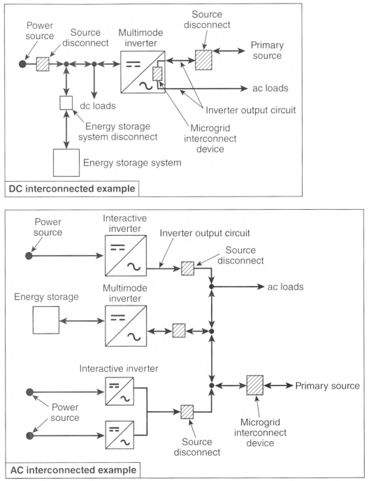
Informational Note No. 1: Examples of the types of primary sources include a utility supply or an on-site electric power source(s).
Informational Note No. 2: See Informational Note Figure 705.1.
Notes:
- These diagrams are intended to be a means of identification for power source components, circuits, and connections.
- The power source disconnect in these diagrams separates the power source from other systems.
- Equipment disconnecting means not shown.
- System grounding and equipment grounding are not shown.
- Custom designs occur in each configuration, and some components are optional.
Informational Note Figure 705.1 Identification of Power Source Components in Common Configurations
705.5 Parallel Operation.
(A) Output Compatibility.
Power production sources operating in parallel with a primary source of electricity or other power production sources shall have compatible voltage, wave shape, and frequency ratings.
(B) Synchronous Generators.
Synchronous generators operating in parallel with a primary power source shall be installed with the required synchronizing equipment.
Informational Note: See IEEE 1547, Standard for Interconnection and Interoperability of Distributed Energy Resources with Associated Electric Power Systems Interfaces, and UL 1741, Standard for Inverters, Converters, Controllers and Interconnection System Equipment for Use with Distributed Energy Resources, for utility interconnection.
705.6 Equipment Approval.
Interconnection and interactive equipment intended to connect to or operate in parallel with power production sources shall be listed for the required interactive function or be evaluated for the interactive function and have a field label applied, or both.
Informational Note No. 1: See UL 1741, Standard for Inverters, Converters, Controllers and Interconnection System Equipment for Use with Distributed Energy Resources, for evaluating interconnected equipment. Sources identified as stand-alone, interactive, or multimode are specifically identified and certified to operate in these operational modes. Stand-alone sources operate in island mode, interactive sources operate in interactive mode, and multimode sources operate in either island mode or interactive mode. Stand-alone sources are not evaluated for interactive capabilities.
Informational Note No. 2: An interactive function is common in equipment such as microgrid interconnect devices, power control systems, interactive inverters, synchronous engine generators, ac energy storage systems, and ac wind turbines.
705.8 System Installation.
Installation of one or more electrical power production sources operating in parallel with a primary source(s) of electricity shall be performed only by qualified persons.
Informational Note: See Article 100 for the definition of Qualified Person.
705.10 Identification of Power Sources.
Permanent plaques, labels, or directories shall be installed at each service equipment location, or at an approved readily visible location in accordance with the following:
- Denote the location of each power source disconnecting means for the building or structure.Exception: Installations with multiple colocated power production sources shall be permitted to be identified as a group(s). The plaque, label, or directory shall not be required to identify each power source individually.
- Indicate the emergency telephone numbers of any off-site entities servicing the power source systems.Informational Note: See NFPA 1-2021, Fire Code, 11.12.2.1.5 for installer information.
- Be marked with the wording "CAUTION: MULTIPLE SOURCES OF POWER." The marking shall comply with 110.21(B).
705.11 Source Connections to a Service.
(A) Service Connections.
An electric power production source shall be permitted to be connected to a service by one of the following methods:
- To a new service in accordance with 230.2(A)
- To the supply side of the service disconnecting means in accordance with 230.82(6)
- To an additional set of service entrance conductors in accordance with 230.40, Exception No. 5
These connections shall comply with 705.11 (B) through (F).
(B) Conductors.
Service conductors connected to power production sources shall comply with the following:
- The ampacity of the service conductors connected to the power production source service disconnecting means shall not be less than the sum of the power production source maximum circuit current in 705.28(A).
- The service conductors connected to the power production source service disconnecting means shall be sized in accordance with 705.28 and not be smaller than 6 AWG copper or 4 AWG aluminum or copper-clad aluminum.
- The ampacity of any other service conductors to which the power production sources are connected shall not be less than that required in 705.11 (B).
(C) Connections.
(2) Existing Equipment.
Any modifications to existing equipment shall be made in accordance with the manufacturer's instructions, or the modification must be field evaluated for the application and be field labeled.
(3) Utility-Controlled Equipment.
For meter socket enclosures or other equipment under the exclusive control of the electric utility, only connections approved by the electric utility shall be permitted.
(D) Service Disconnecting Means.
A disconnecting means in accordance with Parts VI through VII of Article 230 shall be provided to disconnect all ungrounded conductors of a power production source from the conductors of other systems.
(E) Bonding and Grounding.
All metal enclosures, metal wiring methods, and metal parts associated with the service connected to a power production source shall be bonded in accordance with Parts II through V and VIII of Article 250.
(F) Overcurrent Protection.
The power production source service conductors shall be protected from overcurrent in accordance with Part VII of Article 230. The rating of the overcurrent protection device of the power production source service disconnecting means shall be used to determine if ground-fault protection of equipment is required in accordance with 230.95.
705.12 Load-Side Source Connections.
The output of an interconnected electric power source shall be permitted to be connected to the load side of the service disconnecting means of the other source(s) at any distribution equipment on the premises. Where distribution equipment or feeders are fed simultaneously by a primary source of electricity and one or more other power source(s), the feeders or distribution equipment shall comply with relevant sections of 705.12(A) and (B). Currents from power source connections to feeders or busbars shall be based on the maximum circuit currents calculated in 705.28(A). The ampacity of feeders and taps shall comply with 705.12(A), and the ampere ratings of busbars shall comply with 705.12(B).
(A) Feeders and Feeder Taps.
Where the power source output connection is made to a feeder, the following shall apply:
- The feeder ampacity is greater than or equal to 125 percent of the power-source output circuit current.
- Where the power-source output connection is made at a location other than the opposite end of the feeder from the primary source overcurrent device, that portion of the feeder on the load side of the power source output connection shall be protected by one of the following:
- The feeder ampacity shall be not less than the sum of the rating of the primary source overcurrent device and 125 percent of the power-source output circuit current.
- An overcurrent device at the load side of the power source connection point shall be rated not greater than the ampacity of the feeder.
- For taps sized in accordance with 240.21(B)(2) or (B)(4). the ampacity of taps conductors shall not be less than one-third of the sum of the rating of the overcurrent device protecting the feeder plus the ratings of any power source overcurrent devices connected to the feeder.
(B) Busbars.
For power source connections to distribution equipment with no specific listing and instructions for combining multiple sources, one of the following methods shall be used to determine the required ampere ratings of busbars:
- The sum of 125 percent of the power source(s) output circuit current and the rating of the overcurrent device protecting the busbar shall not exceed the busbar ampere rating.Informational Note: This general rule assumes no limitation in the number of the loads or sources applied to busbars or their locations.
- Where two sources, one a primary power source and the other another power source, are located at opposite ends of a busbar that contains loads, the sum of 125 percent of the power-source(s) output circuit current and the rating of the overcurrent device protecting the busbar shall not exceed 120 percent of the busbar ampere rating. The busbar shall be sized for the loads connected in accordance with Article 220. A permanent warning label shall be applied to the distribution equipment adjacent to the back-fed breaker from the power source that displays the following or equivalent wording:
- The sum of the ampere ratings of all overcurrent devices on panelboards, both load and supply devices, excluding the rating of the overcurrent device protecting the busbar, shall not exceed the ampacity of the busbar. The rating of the overcurrent device protecting the busbar shall not exceed the rating of the busbar. Permanent warning labels shall be applied to distribution equipment displaying the following or equivalent wording:
- A connection at either end of a center-fed panelboard in dwellings shall be permitted where the sum of 125 percent of the power-source(s) output circuit current and the rating of the overcurrent device protecting the busbar does not exceed 120 percent of the busbar ampere rating.
- Connections shall be permitted on busbars of panelboards that supply lugs connected to feed-through conductors or are supplied by feed-through conductors. The feed-through conductors shall be sized in accordance with 705.12(A). Where an overcurrent device is installed at either end of the feed-through conductors, panelboard busbars on either side of the feed-through conductors shall be permitted to be sized in accordance with 705.12(B)(1) through (B)(3).
- Connections shall be permitted on switchgear, switchboards, and panelboards in configurations other than those permitted in 705.12(B)(1) through (B)(5) where designed under engineering supervision that includes available fault-current and busbar load calculations.
Informational Note: Specifically designed equipment exists, listed to UL 1741, Inverters, Converters, Controllers and Interconnection System Equipment for Use With Distributed Energy Resources, for the combination and distribution of sources to supply loads. The options provided in 705.12(B) are for equipment with no specific listing for combining sources.
WARNING:
POWER SOURCE OUTPUT DO NOT RELOCATE
THIS OVERCURRENT DEVICE..
The warning sign(s) or label(s) shall comply with 110.21(B).
WARNING:
EQUIPMENT FED BY MULTIPLE SOURCES. TOTAL
RATING OF ALL OVERCURRENT DEVICES EXCLUDING
MAIN SUPPLY OVERCURRENT DEVICE SHALL
NOT EXCEED AMPACITY OF BUSBAR..
The warning sign(s) or label(s) shall comply with 110.21(B).
705.13 Energy Management Systems (EMS).
An EMS in accordance with 750.30 shall be permitted to limit current and loading on the busbars and conductors supplied by the output of one or more interconnected electric power production or energy storage sources.
Informational Note: A listed power control system (PCS) is a type of EMS that is capable of monitoring multiple power sources and controlling the current on busbars and conductors to prevent overloading. See UL 1741, Inverters, Converters, Controllers and Interconnection System Equipment for Use with Distributed Energy Resources, and UL 916, Energy Management Equipment, for information on PCS and EMS.
705.20 Source Disconnecting Means.
Means shall be provided to disconnect power source output conductors of electric power production equipment from conductors of other systems. A single disconnecting means shall be permitted to disconnect multiple power sources from conductors of other systems.
Informational Note: See 480.7, Part II of Article 445, Part III of Article 690, Part III of Article 692, Part III of Article 694, and Part II of Article 706 for specific source disconnecting means requirements.
The disconnecting means shall comply with the following:
- Be one of the following types:
- A manually operable switch or circuit breaker
- A load-break-rated pull-out switch
- A power-operated or remote-controlled switch or circuit breaker that is manually operable locally and opens automatically when control power is interrupted
- A device listed or approved for the intended application
- Simultaneously disconnect all ungrounded conductors of the circuit
- Located where readily accessible
- Externally operable without exposed live parts
- Plainly indicate whether in the open (off) or closed (on) position
- Have ratings sufficient for the maximum circuit current, available fault current, and voltage that is available at the terminals
- Where the line and load terminals are capable of being energized in the open position, be marked with the following words or equivalent:
705.25 Wiring Methods.
(B) Flexible Cords and Cables.
Flexible cords and cables, where used to connect the moving parts of power production equipment, or where used for ready removal for maintenance and repair, shall be listed and identified as DG cable, or other cable suitable for extra hard use, and shall be water resistant. Cables exposed to sunlight shall be sunlight resistant. Flexible, fine-stranded cables shall be terminated only with terminals, lugs, devices, or connectors in accordance with 110.14(A).
(C) Multiconductor Cable Assemblies.
Multiconductor cable assemblies used in accordance with their listings shall be permitted.
Informational Note: See UL 3003, Distributed Generation Cables. and UL 9703, Outline of Investigation for Distributed Generation Wiring Harnesses, for additional information on DG cable (distributed generation cable) and harnesses. An ac module harness is one example of a multiconductor cable assemble.
705.28 Circuit Sizing and Current.
(A) Power Source Output Maximum Current.
Where not elsewhere required or permitted in this Code, the maximum current for power sources shall be calculated using one of the following methods:
- The sum of the continuous output current ratings of the power production equipment at the circuit nominal system voltage
- For power production equipment controlled by an EMS, the current setpoint of the EMS
- Where sources controlled by an EMS are combined with other sources on the same power source output circuit, the sum of 705.28(A)(1) and (A)(2)
(B) Conductor Ampacity.
Where not elsewhere required or permitted in this Code, the power source output conductors shall have an ampacity not less than the larger of the following and comply with 110.14(C):
- The maximum currents in 705.28(A) multiplied by 125 percent without adjustment or correction factorsException No. 1: If the assembly, including the overcurrent devices protecting the circuit, is listed for operation at 100 percent of its rating, the ampacity of the conductors shall be permitted to be not less than the calculated maximum current of 705.28(A).Exception No. 2: Where a portion of a circuit is connected at both its supply and load ends to separately installed pressure connections as covered in 110.14(C)(2), it shall be permitted to have an ampacity not less than the calculated maximum current of 705.28(A). No portion of the circuit installed under this exception shall extend into an enclosure containing either the circuit supply or the circuit load terminations, as covered in 110.14(C)(1).Exception No. 3: Grounded conductors that are not connected to an overcurrent device shall be permitted to be sized at 100 percent of the calculated maximum current of 705.28(A).
- The maximum currents in 705.28(A) after the application of adjustment and correction factors in accordance with 310.14
- Where connected to feeders, if smaller than the feeder conductors, the ampacity as calculated in 240.21(B) based on the over-current device protecting the feeder
(C) Neutral Conductors.
(1) Single-Phase Line-to-Neutral Power Sources.
Where not elsewhere required or permitted in this Code, the ampacity of a neutral conductor to which a single-phase line-to-neutral power source is connected shall not be smaller than the ampacity in 705.28(B).
(2) Neutral Conductor Used Solely for Instrumentation. Voltage, Detection, or Phase Detection.
A power production equipment neutral conductor used solely for instrumentation, voltage detection, or phase detection shall be permitted to be sized in accordance with 250.102.
705.30 Overcurrent Protection.
(A) Circuit and Equipment.
Power source output conductors and equipment shall be provided with overcurrent protection. Circuits connected to more than one electrical source shall have overcurrent devices located to provide overcurrent protection from all sources.
(B) Overcurrent Device Ratings.
The overcurrent devices in other than generator systems shall be sized to carry not less than 125 percent of the maximum currents as calculated in 705.28(A). The rating or setting of overcurrent devices shall be permitted in accordance with 240.4(B) and (C).
Exception: Circuits containing an assembly together with its overcurrent device(s) that is listed for continuous operation at 100 percent of its rating shall be permitted to be utilized at 100 percent of its rating.
(C) Marking.
Equipment containing overcurrent devices supplied from interconnected power sources shall be marked to indicate the presence of all sources.
(D) Suitable for Backfeed.
Fused disconnects, unless otherwise marked, shall be considered suitable for backfeed. Circuit breakers not marked "line" and "load" shall be considered suitable for backfeed. Circuit breakers marked "line" and "load" shall be considered suitable for backfeed or reverse current if specifically rated.
(E) Fastening.
Listed plug-in-type circuit breakers backfed from electric power sources that are listed and identified as interactive shall be permitted to omit the additional fastener normally required by 408.36(D) for such applications.
(F) Transformers.
The following apply to the installation of transformers:
- For the purpose of overcurrent protection, the primary side of transformers with sources on each side shall be the side connected to the largest source of available fault current.
- Transformer secondary conductors shall be protected in accordance with 240.21 (C).
705.32 Ground-Fault Protection.
Where ground-fault protection of equipment is installed in ac circuits as required elsewhere in this Code, the output of interconnected power production equipment shall be connected to the supply side of the ground-fault protection equipment.
Exception: Connection of power production equipment shall be permitted to be made to the load side of ground-fault protection equipment where installed in accordance with 705.11 or where there is ground-fault protection for equipment from all ground-fault current sources.
705.40 Loss of Primary Source.
The output of interactive electric power production equipment shall be automatically disconnected from all ungrounded conductors of the primary source when one or more of the phases of the primary source to which it is connected opens. The interactive electric power production equipment shall not be reconnected to the primary source until all the phases of the primary source to which it is connected are restored. This requirement shall not be applicable to electric power production equipment providing power to an emergency or legally required standby system.
Exception: A listed interactive inverter shall trip or shall be permitted to automatically cease exporting power when one or more of the phases of the interconnected primary source opens and shall not be required to automatically disconnect all ungrounded conductors from the primary source. A listed interactive inverter shall be permitted to automatically or manually resume exporting power to the interconnected system once all phases of the source to which it is connected are restored.
Informational Note No. 1: Risks to personnel and equipment associated with the primary source could occur if an interactive electric power production source can operate as an intentional island. Special detection methods are required to determine that a primary source supply system outage has occurred and whether there should be automatic disconnection. When the primary source supply system is restored, special detection methods are typically required to limit exposure of power production sources to out-of-phase reconnection.
Informational Note No. 2: Induction-generating equipment connected on systems with significant capacitance can become self-excited upon loss of the primary source and experience severe overvoltage as a result.
Interactive power production equipment shall be permitted to operate in island mode to supply loads that have been disconnected from the electric utility or other electric power production and distribution network.
705.45 Unbalanced Interconnections.
(A) Single Phase.
Single-phase power sources in interactive systems shall be connected to 3-phase power systems in order to limit unbalanced voltages at the point of interconnection to not more than 3 percent.
(B) Three Phase.
Three-phase power sources in interactive systems shall have all phases automatically de-energized upon loss of, or unbalanced, voltage in one or more phases unless the interconnected system is designed so that significant unbalanced voltages will not result.
705.50 System Operation.
Interconnected microgrid systems shall be capable of operating in interactive mode with a primary source of power, or electric utility, or other electric power production and distribution network. Microgrid systems shall be permitted to disconnect from other sources and operate in island mode.
Informational Note No. 1: Microgrid systems often include a single source or a compatible interconnection of multiple sources such as engine generators, solar PV, wind, or ESS.
705.60 Primary Power Source Connection.
Connections to primary power sources that are external to the microgrid system shall comply with the requirements of 705.11, 705.12, or 705.13. Power source conductors connecting to a microgrid system, including conductors supplying distribution equipment, shall be considered as power source output conductors.
705.70 Microgrid Interconnect Devices (MID).
Microgrid interconnect devices shall comply with the following:
- Be required for any connection between a microgrid system and a primary power source
- Be evaluated for the application and have a field label applied or be listed for the application
- Have overcurrent devices located to provide overcurrent protection from all sources
Informational Note: MID functionality is often incorporated in an interactive or multimode inverter, energy storage system, or similar device identified for interactive operation.
705.76 Microgrid Control System (MCS).
Microgrid control systems shall comply with the following:
- Coordinate interaction between multiple power sources of similar or different types, manufacturers, and technologies (including energy storage)
- Be evaluated for the application and have a field label applied, or be listed, or be designed under engineering supervision
- Monitor and control microgrid power production and power quality
- Monitor and control transitions with a primary source external to the microgrid
Informational Note: MID functionality is often incorporated in an interactive or multimode inverter, energy storage system, or similar device identified for interactive operation.
705.80 Power Source Capacity.
For interconnected power production sources that operate in island mode, capacity shall be calculated using the sum of all power source output maximum currents for the connected power production source.
705.81 Voltage and Frequency Control.
Power sources operating in island mode shall be controlled so that voltage and frequency are supplied within limits compatible with the connected loads.
705.82 Single 120-Volt Supply.
Systems operating in island mode shall be permitted to supply 120 volts to single-phase, 3-wire, 120/240-volt distribution equipment where there are no 240-volt outlets and where there are no multiwire branch circuits. In all installations, the sum of the ratings of the power sources shall be less than the rating of the neutral bus in the distribution equipment. This equipment shall be marked with the following words or equivalent:
WARNING:
SINGLE 120-VOLT SUPPLY
DO NOT CONNECT MULTIWIRE BRANCH CIRCUITS.
The warning sign(s) or label(s) shall comply with 110.21(B).
Article 706
Energy Storage Systems
706.1 Scope.
This article applies to all energy storage systems (ESS) having a capacity greater than 3.6 MJ (1 kWh) that may be stand-alone or interactive with other electric power production sources. These systems are primarily intended to store and provide energy during normal operating conditions.
Informational Note No. 1: See Article 480 for installations that meet the definition of stationary standby batteries.
Informational Note No. 2: For batteries rated in ampere hours, kWh is equal to the nominal rated voltage times ampere-hour rating divided by 1000.
Informational Note No. 3: The following standards are frequently referenced for the installation of ESSs:
- NFPA 1-2021, Fire Code
- NFPA 111-2019, Standard on Stored Electrical Energy Emergency and Standby Power Systems
- NECA 416-2016, Recommended Practice for Installing Energy Storage Systems (ESS)
- UL 810A, Electrochemical Capacitors
- NFPA 855-2020, Standard for the Installation of Stationary Energy Storage Systems
- UL 1973, Standard for Batteries for Use in Stationary, Vehicle Auxiliary Power, and Light Electric Rail (LER) Applications
- UL 1989, Standard for Standby Batteries
- UL 9540, Standard for Safety Energy Storage Systems and Equipment
- UL Subject 2436, Spill Containment For Stationary Lead Acid Battery Systems
706.3 Qualified Personnel.
The installation and maintenance of ESS equipment and all associated wiring and interconnections shall be performed only by qualified persons.
Informational Note: See Article 100 for the definition of qualified person.
706.4 System Requirements.
Each ESS shall be provided with a nameplate plainly visible after installation and marked with the following:
- Manufacturer's name, trademark, or other descriptive marking by which the organization responsible for supplying the ESS can be identified
- Rated frequency
- Number of phases, if ac
- Rating (kW or kVA)
- Available fault current derived by the ESS at the output terminals
- Maximum output and input current of the ESS at the output terminals
- Maximum output and input voltage of the ESS at the output terminals
- Utility-interactive capability, if applicable
706.5 Listing.
Energy storage systems shall be listed.
706.7 Commissioning and Maintenance.
(A) Commissioning.
ESSs shall be commissioned upon installation. This shall not apply in one- and two-family dwellings.
Informational Note: See NFPA 855-2020, Standard for the Installation of Stationary Energy Storage Systems, for information related to the commissioning of ESSs.
(B) Maintenance.
ESSs shall be maintained in proper and safe operating condition. The required maintenance shall be in accordance with the manufacturer's requirements and industry standards. A written record of the system maintenance shall be kept and shall include records of repairs and replacements necessary to maintain the system in proper and safe operating condition. This shall not apply in one- and two-family dwellings.
Informational Note: See NFPA 70B-2019, Recommended Practice for Electrical Equipment Maintenance, or ANSI/NETA ATS-2017, Standard for Acceptance Testing Specifications for Electrical Power Equipment and Systems, for information related to general electrical equipment maintenance and developing an effective electrical preventive maintenance (EPM) program.
706.9 Maximum Voltage.
The maximum voltage of an ESS shall be the rated ESS input and output voltage(s) indicated on the ESS nameplate(s) or system listing.
706.15 Disconnecting Means.
(A) ESS Disconnecting Means.
Means shall be provided to disconnect the ESS from all wiring systems, including other power systems, utilization equipment, and its associated premises wiring.
(B) Location and Control.
The disconnecting means shall be readily accessible and shall comply with one or more of the following:
- Located within the ESS
- Located within sight and within 3 m (10 ft) from the ESS
- Where not located within sight of the ESS, the disconnecting means, or the enclosure providing access to the disconnecting means, shall be capable of being locked in accordance with 110.25
Where controls to activate the disconnecting means of an ESS are used and are not located within sight of the ESS, the disconnecting means shall be lockable in accordance with 110.25, and the location of the controls shall be marked on the disconnecting means.
For one- and two-family dwellings, an ESS shall include an emergency shutdown function to cease the export of power from the ESS to premises wiring of other systems. An initiation device(s) shall be located at a readily accessible location outside the building and shall plainly indicate whether in the "off" or "on" position. The "off" position of the device(s) shall perform the ESS emergency shutdown function.
(C) Notification and Marking.
Each ESS disconnecting means shall plainly indicate whether it is in the open (off) or closed (on) position and be permanently marked as follows:
"ENERGY STORAGE SYSTEM DISCONNECT"
The disconnecting means shall be legibly marked in the field to indicate the following:
- Nominal ESS output voltage
- Available fault current derived from the ESS
- An arc-flash label applied in accordance with acceptable industry practice
- Date the calculation was performed
Exception: List items (2), (3), and (4) shall not apply to one- and two- family dwellings.
Informational Note No. 1: See NFPA 70E-2018, Standard for Electrical Safety in the Workplace, for industry practices for equipment labeling. This standard provides specific criteria for developing arc-flash labels for equipment that provides nominal system voltage, incident energy levels, arc-flash boundaries, minimum required levels of personal protective equipment, and so forth.
Informational Note No. 2: ESS electronics could include inverters or other types of power conversion equipment.
For ESS disconnecting means where the line and load terminals could be energized in the open position, the device shall be marked with the following words or equivalent:
WARNING
ELECTRIC SHOCK HAZARD
TERMINALS ON THE LINE AND LOAD SIDES MAY BE
ENERGIZED IN THE OPEN POSITION.
The notification(s) and marking(s) shall comply with 110.21(B).
(D) Partitions Between Components.
Where circuits from the input or output terminals of energy storage components in an ESS pass through a wall, floor, or ceiling, a readily accessible disconnecting means shall be provided within sight of the energy storage component. Fused disconnecting means or circuit breakers shall be permitted to be used.
(E) Disconnecting Means for Batteries.
In cases where the battery is separate from the ESS electronics and is subject to field servicing, 706.15(E)(1) through (E)(4) shall apply.
(1) Disconnecting Means.
A disconnecting means shall be provided for all ungrounded conductors. A disconnecting means shall be readily accessible and located within sight of the battery.
Informational Note: See 240.21(H) for information on the location of the overcurrent device for battery conductors.
(3) Remote Activation.
Where a disconnecting means is provided with remote controls to activate the disconnecting means and the controls for the disconnecting means are not located within sight of the battery, the disconnecting means shall be capable of being locked in the open position, in accordance with 110.25, and the location of the controls shall be field marked on the disconnecting means.
(4) Notification.
The disconnecting means shall be legibly marked in the field. The marking shall be of sufficient durability to withstand the environment involved and shall include the following:
- Nominal battery voltage
- Available fault current derived from the stationary standby battery systemInformational Note No. 1: Battery equipment suppliers can provide information about available fault current on any particular battery model.
- An arc-flash label in accordance with acceptable industry practiceInformational Note No. 2: See NFPA 70E-2021, Standard for Electrical Safety in the Workplace, for assistance in determining the severity of potential exposure, planning safe work practices, determining arc-flash labeling, and selecting personal protective equipment.
- Date the calculation was performed
706.16 Connection to Energy Sources.
(A) Source Disconnect.
A disconnect that has multiple sources of power shall disconnect all energy sources when in the off position.
(B) Identified Interactive Equipment.
ESS that operate in parallel with other ac sources shall use inverters that are listed and identified as interactive.
(C) Loss of Interactive System Power.
Upon loss of a primary source of power, an ESS with a utility-interactive inverter shall comply with the requirements of 705.40.
706.20 General.
(A) Ventilation.
Provisions appropriate to the energy storage technology shall be made for sufficient diffusion and ventilation of any possible gases from the storage device, if present, to prevent the accumulation of an explosive mixture. Ventilation of an ESS shall be permitted to be provided in accordance with the manufacturer's recommendations and listing for the system.
Informational Note No. 1: See NFPA 855-2020, Standard for the Installation of Stationary Energy Storage Systems, for technology-specific guidance. Not all ESS technologies require ventilation.
(B) Dwelling Units.
An ESS for one- and two-family dwelling units shall not exceed 100 volts dc between conductors or to ground.
Exception: Where live parts are not accessible during routine ESS maintenance, a maximum ESS voltage of 600 volts dc shall be permitted.
706.21 Directory (Identification of Power Sources).
706.30 Circuit Sizing and Current.
(A) Maximum Rated Current for a Specific Circuit.
The maximum current for the specific circuit shall be calculated in accordance with 706.30(A)(1) through (A)(5).
(1) Nameplate-Rated Circuit Current.
Circuit current shall be the rated current indicated on the ESS nameplate(s) or system listing. Where the ESS has separate input (charge) and output (discharge) circuits or ratings, these shall be considered individually. Where the same terminals on the ESS are used for charging and discharging, the rated current shall be the greater of the two.
(3) Inverter Input Circuit Current.
The maximum current shall be the continuous inverter input current rating when the inverter is producing rated power at the lowest input voltage.
(4) Inverter Utilization Output Circuit Current.
The maximum current shall be the continuous ac output current rating of the inverter when the inverter is producing rated power.
(B) Conductor Ampacity.
The ampacity of the output circuit conductors of the ESS(s) connected to the wiring system serving the loads to be serviced by the system shall not be less than the greater of the nameplate(s)-rated circuit current as determined in accordance with 706.30(A)(1) or the rating of the ESS(s) overcurrent protective device(s).
(C) Ampacity of Grounded or Neutral Conductor.
If the output of a single-phase, 2-wire ESS output(s) is connected to the grounded or neutral conductor and a single ungrounded conductor of a 3-wire system or of a 3-phase, 4-wire, wye-connected system, the maximum unbalanced neutral load current plus the ESS(s) output rating shall not exceed the ampacity of the grounded or neutral conductor.
706.31 Overcurrent Protection.
(A) Circuits and Equipment.
Protection devices for ESS circuits shall be in accordance with 706.31(B) through (F). Circuits shall be protected at the source from overcurrent. A circuit conductor connected at one end to a supply with integral fault protection, where the conductor is rated for the maximum circuit current from that supply, and also connected to sources having an available maximum circuit current greater than the ampacity of the conductor, shall be protected from overcurrent at the point of connection to the higher current source.
Informational Note: Listed electronic power converter circuits powered by an ESS have integral fault protection. Where these circuits are connected to higher current sources such as a utility service, the overcurrent device is more appropriately installed at the higher current source end of the circuit conductor.
(B) Overcurrent Device Ampere Ratings.
Overcurrent protective devices, where required, shall be not less than 125 percent of the maximum currents calculated in 706.30(A).
Exception: Where the assembly, including the overcurrent protective devices, is listed for operation at 100 percent of its rating, the ampere rating of the overcurrent devices shall be permitted to be not less than the maximum currents calculated in 706.30(B).
(C) Direct Current Rating.
Overcurrent protective devices, either fuses or circuit breakers, used in any dc portion of an ESS shall be listed for dc and shall have the appropriate voltage, current, and interrupting ratings for the application.
(D) Current Limiting.
A listed and labeled current-limiting overcurrent protective device shall be installed adjacent to the ESS for each dc output circuit.
Exception: Where current-limiting overcurrent protection is provided for the dc output circuits of a listed ESS, additional current-limiting overcurrent devices shall not be required.
(E) Fuses.
Means shall be provided to disconnect any fuses associated with ESS equipment and components when the fuse is energized from both directions and is accessible to other than qualified persons. Switches, pullouts, or similar devices that are rated for the application shall be permitted to serve as a means to disconnect fuses from all sources of supply.
(F) Location.
Where circuits from the input or output terminals of energy storage components in an ESS pass through a wall, floor, or ceiling, overcurrent protection shall be provided at the energy storage component end of the circuit.
706.33 Charge Control.
(B) Diversion Charge Controller.
(1) Sole Means of Regulating Charging.
An ESS employing a diversion charge controller as the sole means of regulating charging shall be equipped with a second independent means to prevent overcharging of the storage device.
(2) Circuits With Diversion Charge Controller and Diversion Load.
Circuits containing a diversion charge controller and a diversion load shall comply with the following:
- The current rating of the diversion load shall be less than or equal to the current rating of the diversion load charge controller. The voltage rating of the diversion load shall be greater than the maximum ESS voltage. The power rating of the diversion load shall be at least 150 percent of the power rating of the charging source.
- The conductor ampacity and the rating of the overcurrent device for this circuit shall be at least 150 percent of the maximum current rating of the diversion charge controller.
(3) ESS Using Interactive Inverters.
Systems using interactive inverters to control energy storage state-of-charge by diverting excess power into an alternate electric power production and distribution system, such as utility, shall comply with 706.33(B)(3)(a) and (B)(3)(b).
- These systems shall not be required to comply with 706.33(B)(2).
- These systems shall have a second, independent means of controlling the ESS charging process for use when the alternate system is not available or when the primary charge controller fails or is disabled.
(C) Charge Controllers and DC-to-DC Converters.
Where charge controllers and other DC-to-DC power converters that increase or decrease the output current or output voltage with respect to the input current or input voltage are installed, all of the following shall apply:
- The ampacity of the conductors in output circuits shall be based on the maximum rated continuous output current of the charge controller or converter for the selected output voltage range.
- The voltage rating of the output circuits shall be based on the maximum voltage output of the charge controller or converter for the selected output voltage range.
Part V. Flow Battery ESSs
Part V applies to ESSs composed of or containing flow batteries.
Informational Note: Due to the unique design features and difference in operating characteristics of flow batteries as compared with that of storage batteries such as lead acid or lithium ion batteries, the requirements for flow batteries have been included herein (Article 706, Part V).
706.40 General.
The system and system components shall also meet Parts I, II, and III of this article.
Informational Note: See NFPA 855-2020, Standard for the Installation of Stationary Energy Storage Systems, for installation requirements for ESS, including requirements for flow batteries.
706.41 Electrolyte Classification.
The electrolyte(s) that are acceptable for use in the batteries associated with the ESS shall be identified by name and chemical composition. Such identification shall be provided by readily discernable signage adjacent to every location in the system where the electrolyte can be put into or taken out of the system.
706.42 Electrolyte Containment.
Flow battery systems shall be provided with a means for electrolyte containment to prevent spills of electrolyte from the system. An alarm system shall be provided to signal an electrolyte leak from the system. Electrical wiring and connections shall be located and routed in a manner that mitigates the potential for exposure to electrolytes.
706.44 Pumps and Other Fluid Handling Equipment.
Pumps and other fluid handling equipment are to be rated/specified suitable for exposure to the electrolytes.
Part VI. Other Energy Storage Technologies
Part VI Applies to ESSs Using Other Technologies Intended to Store Energy and When There Is a Demand for Electrical Power to Use the Stored Energy to Generate the Needed Power
706.50 General.
All electrical connections to and from the system and system components shall be in accordance with the applicable provisions of this Code. The systems shall comply with Parts I, II, III, and IV of this article.
706.51 Flywheel ESS (FESS).
Flywheel ESS (FESS) using flywheels as the storage mechanism shall also comply with all of the following:
- FESS shall not be used for one- or two-family dwelling units.Informational Note No. 1: FESS are intended for high-power shorter term applications. They contain parts that rotate under high speed with hazardous kinetic energy and include parts such as magnetic bearings that require ongoing monitoring and maintenance and, therefore, are not suitable for residential-type applications.
- FESS shall be provided with bearing monitoring and controls that can identify bearing wear or damage to avoid catastrophic failure.Informational Note No. 2: The bearing monitoring controls should be evaluated as part of the listing evaluation.
- FESS shall be provided with a containment means to contain moving parts that could break from the system upon catastrophic failure.Informational Note No. 3: The containment means should be evaluated as part of the listing evaluation.
- The spin-down time of the FESS shall be provided in the maintenance documentation.
Article 708
Critical Operations Power Systems (COPS)
708.1 Scope.
This article applies to the installation, operation, monitoring, control, and maintenance of the portions of the premises wiring system intended to supply, distribute, and control electricity to designated critical operations areas (DCOA) in the event of disruption to elements of the normal system.
Critical operations power systems are those systems so classed by municipal, state, federal, or other codes by any governmental agency having jurisdiction or by facility engineering documentation establishing the necessity for such a system. These systems include but are not limited to power systems, HVAC, fire alarm, security, communications, and signaling for designated critical operations areas.
Informational Note No. 1: Critical operations power systems are generally installed in vital infrastructure facilities that, if destroyed or incapacitated, would disrupt national security, the economy, public health or safety; and where enhanced electrical infrastructure for continuity of operation has been deemed necessary by governmental authority.
Informational Note No. 2: See NFPA 1600-2019, Standard on Continuity, Emergency, and Crisis Management, for further information on disaster and emergency management.
Informational Note No. 3: See NFPA 110-2019, Standard for Emergency and Standby Power Systems, for further information regarding performance of emergency and standby power systems.
Informational Note No. 4: See NFPA 707-2021, Life Safety Code, or the applicable building code, for specification of locations where emergency lighting is considered essential to life safety.
Informational Note No. 5: See NFPA 730-2020, Guide for Premises Security, and ANSI/TIA-5017-2016, Telecommunications Physical Network Security Standard, for further information regarding physical security.
Informational Note No. 6: See NFPA 1600-2019, Standard on Continuity, Emergency, and Crisis Management, A.5.3.2. Threats to facilities that may require transfer of operation to the critical systems include both naturally occurring hazards and human-caused events.
Informational Note No. 7: See Informative Annex F, Availability and Reliability for Critical Operations Power Systems; and Development and Implementation of Functional Performance Tests (FPTs) for Critical Operations Power Systems.
Informational Note No. 8: See Informative Annex G, Supervisory Control and Data Acquisition (SCADA).
Informational Note No. 9: Text that is followed by a reference in brackets has been extracted from NFPA 1600-2019, Standard on Continuity, Emergency, and Crisis Management. Only editorial changes were made to the extracted text to make it consistent with this Code.
708.4 Risk Assessment.
Risk assessment for critical operations power systems shall be documented and shall be conducted in accordance with 708.4(A) through (C).
Informational Note: See NFPA 1600-2019, Standard on Continuity, Emergency, and Crisis Management, Chapter 5, which provides additional guidance concerning risk assessment and hazard analysis.
(A) Conducting Risk Assessment.
In critical operations power systems, risk assessment shall be performed to identify hazards, the likelihood of their occurrence, and the vulnerability of the electrical system to those hazards.
(B) Identification of Hazards.
Hazards to be considered at a minimum shall include, but shall not be limited to, the following:
- Naturally occurring hazards (geological, meteorological, and biological)
- Human-caused events (accidental and intentional)
(C) Developing Mitigation Strategy.
Based on the results of the risk assessment, a strategy shall be developed and implemented to mitigate the hazards that have not been sufficiently mitigated by the prescriptive requirements of this Code.
708.5 Physical Security.
Physical security shall be provided for critical operations power systems in accordance with 708.5(A) and (B).
(A) Risk Assessment.
Based on the results of the risk assessment, a strategy for providing physical security for critical operations power systems shall be developed, documented, and implemented.
(B) Restricted Access.
Electrical circuits and equipment for critical operations power systems shall be accessible to qualified personnel only.
708.6 Testing and Maintenance.
(A) Conduct or Witness Test.
The authority having jurisdiction shall conduct or witness a test of the complete system upon installation and periodically afterward.
(B) Tested Periodically.
Systems shall be tested periodically on a schedule approved by the authority having jurisdiction to ensure the systems are maintained in proper operating condition.
(C) Maintenance.
The authority having jurisdiction shall require a documented preventive maintenance program for critical operations power systems.
Informational Note: See NFPA 70B-2019, Recommended Practice for Electrical Equipment Maintenance, for information concerning maintenance.
(D) Written Record.
A written record shall be kept of such tests and maintenance.
(E) Testing Under Load.
Means for testing all critical power systems during maximum anticipated load conditions shall be provided.
Informational Note: See NFPA 110-2019, Standard for Emergency and Standby Power Systems, for information concerning testing and maintenance of emergency power supply systems (EPSSs) that are also applicable to COPS.
708.7 Cybersecurity.
COPS that are connected to a communication network and have the capability to permit control of any portion of the premises COPS shall comply with either of the following:
- The ability to control the system is limited to a direct connection through a local nonnetworked interface.
- It is connected through a networked interface complying with one of the following methods:
- The system and associated software are identified as being evaluated for cybersecurity.
- A cybersecurity assessment is conducted on the connected system to determine vulnerabilities to cyberattacks.
The cybersecurity assessment shall be conducted when the system configuration changes and at not more than 5-year intervals.
Documentation of the evaluation, assessment, and certification shall be made available to those authorized to inspect, operate, and maintain the system.
Informational Note No. 1: See ANSI/ISA 62443, Cybersecurity Standards series; UL 2900, Cybersecurity Standards series; or the NIST Framework for Improving Critical infrastructure Cybersecurity, Version 1.1, for assessment requirements.
Informational Note No. 2: Examples of the commissioning certification used to demonstrate the system has been investigated for cybersecurity vulnerabilities could be one of the following:
- The ISA Security Compliance Institute (ISCI) conformity assessment program
- Certification of compliance by a nationally recognized test laboratory
- Manufacturer certification for the specific type and brand of system provided
708.8 Commissioning.
(A) Commissioning Plan.
A commissioning plan shall be developed and documented.
Informational Note No. 1: See NFPA 70B-2019, Recommended Practice for Electrical Equipment Maintenance, for further information on developing a commissioning program.
Informational Note No. 2: See 708.7 for cybersecurity assessments.
(C) Baseline Test Results.
A set of baseline test results shall be documented for comparison with future periodic maintenance testing to identify equipment deterioration.
(D) Functional Performance Tests.
A functional performance test program shall be established, documented, and executed upon complete installation of the critical system in order to establish a baseline reference for future performance requirements.
Informational Note: See Informative Annex F, Availability and Reliability for Critical Operations Power Systems; and Development and Implementation of Functional Performance Tests (FPTs) for Critical Operations Power Systems, for more information on developing and implementing a functional performance test program.
708.10 Feeder and Branch Circuit Wiring.
(A) Identification.
(1) Boxes and Enclosures.
In a building or at a structure where a critical operations power system and any other type of power system are present, all boxes and enclosures (including transfer switches, generators, and power panels) for critical operations power system circuits shall be permanently marked so they will be readily identified as a component of the critical operations power system.
(2) Receptacle Identification.
In a building in which COPS are present with other types of power systems described in other sections in this article, the cover plates for the receptacles or the receptacles themselves supplied from the COPS shall have a distinctive color or marking so as to be readily identifiable. Nonlocking-type, 125-volt, 15- and 20-ampere receptacles supplied from the COPS shall have an illuminated face or an indicator light to indicate that there is power to the receptacle.
Exception: If the COPS supplies power to a DCOA that is a stand-alone building, receptacle cover plates or the receptacles themselves shall not be required to have distinctive marking.
(B) Wiring.
Wiring of two or more COPS circuits supplied from the same source shall be permitted in the same raceway, cable, box, or cabinet. In other than transfer equipment enclosures, wiring from a COPS source or COPS source distribution overcurrent protection to critical loads shall be kept entirely independent of all other wiring and equipment.
(C) COPS Feeder Wiring Requirements.
COPS feeders shall comply with 708.10(C)(1) through (C)(3).
(1) Protection Against Physical Damage.
The wiring of the COPS system shall be protected against physical damage. Only the following wiring methods shall be permitted:
- Rigid metal conduit, intermediate metal conduit, or Type Ml cable.
- Where encased in not less than 50 mm (2 in.) of concrete, any of the following wiring methods shall be permitted:
- Where provisions must be made for flexibility at equipment connection, one or more of the following shall also be permitted:
(2) Fire Protection for Feeders.
Feeders shall meet one of the following conditions:
- The cable or raceway is protected by a listed electrical circuit protective system with a minimum 2-hour fire rating.Informational Note No. 1: See UL 1724, Fire Tests for Electrical Circuit Protective Systems, for one method of defining an electrical circuit protective system, by establishing a rating when tested. UL Guide Information for Electrical Circuit Integrity Systems (FHIT) contains information to identify the system and its installation limitations to maintain a minimum 2-hour fire resistive rating.
- Informational Note No. 2: See UL 2196-2017, Standard for Fire Test for Circuit Integrity of Fire-Resistive Power, Instrumentation, Control and Data Cables, for testing requirements for fire-resistive cables.Informational Note No. 3: The listing organization provides information for fire-resistive cable systems on proper installation requirements to maintain the fire rating.
- The cable or raceway is protected by a listed fire-rated assembly that has a minimum fire rating of 2 hours.
- The cable or raceway is encased in a minimum of 50 mm (2 in.) of concrete.
(3) Floodplain Protection.
Where COPS feeders are installed below the level of the 100-year floodplain, the insulated circuit conductors shall be listed for use in a wet location and be installed in a wiring method that is permitted for use in wet locations.
(D) COPS Branch Circuit Wiring.
- Outside the DCOA. COPS branch circuits installed outside the DCOA shall comply with the physical and fire protection requirements of 708.10(C)(1) through (C)(3).
- Within the DCOA. Any of the wiring methods recognized in Chapter 3 of this Code shall be permitted within the DCOA.
708.11 Branch Circuit and Feeder Distribution Equipment.
(A) Branch Circuit Distribution Equipment.
COPS branch circuit distribution equipment shall be located within the same DCOA as the branch circuits it supplies.
(B) Feeder Distribution Equipment.
Equipment for COPS feeder circuits (including transfer equipment, transformers, and panelboards) shall comply with the following:
- Be located in spaces with a 2-hour fire resistance rating
- Be located above the 100-year floodplain
708.12 Feeders and Branch Circuits Supplied by COPS.
Feeders and branch circuits supplied by the COPS shall supply only equipment specified as required for critical operations use.
708.14 Wiring of HVAC, Fire Alarm, Security, Emergency Communications, and Signaling Systems.
All conductors or cables shall be installed using any of the metal wiring methods permitted by 708.10(C)(1) and, in addition, shall comply with the following, as applicable:
- All cables for fire alarm, security, signaling systems, and emergency communications shall be shielded twisted pair cables or installed to comply with the performance requirements of the system.
- Shields of cables for fire alarm, security, signaling systems, and emergency communications shall be arranged in accordance with the manufacturer's published installation instructions.
- Optical fiber cables shall be used for connections between two or more buildings on the property and under single management.
- A listed primary protector shall be provided on all communications circuits. Listed secondary protectors shall be provided at the terminals of the communications circuits.
- Conductors for all control circuits rated above 50 volts shall be rated not less than 600 volts.
- Communications, fire alarm, and signaling circuits shall use relays with contact ratings that exceed circuit voltage and current ratings in the controlled circuit.
- All cables for fire alarm, security, emergency communications, and signaling systems shall be riser-rated and shall be part of a listed 2-hour fire-resistive cable system or protected by a listed 2-hour electrical circuit protective system.
- Control, monitoring, and power wiring to HVAC systems shall be part of a listed 2-hour fire-resistive cable system or protected by a listed 2-hour electrical circuit protective system.
708.20 Sources of Power.
(A) General Requirements.
Current supply shall be such that, in the event of failure of the normal supply to the DCOA, critical operations power shall be available within the time required for the application. The supply system for critical operations power, in addition to the normal services to the building and meeting the general requirements of this section, shall be one or more of the types of systems described in 708.20(E) through (H).
Informational Note No. 1: Assignment of degree of reliability of the recognized critical operations power system depends on the careful evaluation in accordance with the risk assessment.
Informational Note No. 2: See IEEE 3006.5—2014, Recommended Practice for the Use of Probability Methods for Conducting a Reliability Analysis of Industrial and Commercial Power Systems, for guidance about determining degree of reliability.
(C) Grounding.
All sources of power shall be grounded as a separately derived source in accordance with 250.30.
Exception: Where installed in accordance with 708.10(C) and 708.11(B), equipment containing the main bonding jumper or system bonding jumper for the normal source and the feeder wiring to the transfer equipment shall not be required to be grounded as a separately derived source.
(F) Generator Set.
(1) Prime Mover-Driven.
Generator sets driven by a prime mover shall be provided with means for automatically starting the prime mover on failure of the normal power source. A time-delay feature permitting a minimum 15-minute setting shall be provided to avoid retransfer in case of short-time reestablishment of the normal source.
(2) Power for Fuel Transfer Pumps.
Where power is needed for the operation of the fuel transfer pumps to deliver fuel to a generator set day tank, this pump shall be connected to the COPS.
(3) Dual Supplies.
Prime movers shall not be solely dependent on a public utility gas system for their fuel supply or municipal water supply for their cooling systems. Means shall be provided for automatically transferring from one fuel supply to another where dual fuel supplies are used.
(4) Battery Power and Dampers.
Where a storage battery is used for control or signal power or as the means of starting the prime mover, it shall be suitable for the purpose and shall be equipped with an automatic charging means independent of the generator set. Where the battery charger is required for the operation of the generator set, it shall be connected to the COPS. Where power is required for the operation of dampers used to ventilate the generator set, the dampers shall be connected to the COPS.
(5) Outdoor Generator Sets.
- Permanently Installed Generators and Portable Generators Greater Than 15 kW. Where an outdoor housed generator set is equipped with a readily accessible disconnecting means in accordance with 445.18, and the disconnecting means is located within sight of the building or structure supplied, an additional disconnecting means shall not be required where ungrounded conductors serve or pass through the building or structure. Where the generator supply conductors terminate at a disconnecting means in or on a building or structure, the disconnecting means shall meet the requirements of 225.36.
- Portable Generators 15 kW or Less. Where a portable generator, rated 15 kW or less, is installed using a flanged inlet or other cord-and plug-type connection, a disconnecting means shall not be required where ungrounded conductors serve or pass through a building or structure.
(7) On-Site Fuel Supply.
Where internal combustion engines are used as the prime mover, an on-site fuel supply shall be provided. The on-site fuel supply shall be secured and protected in accordance with the risk assessment.
(G) Uninterruptible Power Supplies.
Uninterruptible power supplies used as the sole source of power for COPS shall comply with 708.20(E) and (F).
(H) Fuel Cell System.
Installation of a fuel cell system shall meet the requirements of Parts II through VIII of Article 692.
708.21 Ventilation.
Adequate ventilation shall be provided for the alternate power source for continued operation under maximum anticipated ambient temperatures.
Informational Note: See NFPA 110-2019, Standard for Emergency and Standby Power Systems, and NFPA 111-2019, Standard on Stored Electrical Energy Emergency and Standby Power Systems, for additional information on ventilation air for combustion and cooling.
708.22 Capacity of Power Sources.
(A) Capacity and Rating.
A COPS shall have capacity and rating for all loads to be operated simultaneously for continuous operation with variable load for an unlimited number of hours, except for required maintenance of the power source. A portable, temporary, or redundant alternate power source shall be available for use whenever the COPS power source is out of service for maintenance or repair.
(B) Selective Load Management.
The alternate power source shall be permitted to supply COPS emergency, legally required standby, and optional loads where the source has adequate capacity or where load management (that includes automatic selective load pickup and load shedding) is provided as needed to ensure adequate power to (1) the COPS and emergency circuits, (2) the legally required standby circuits, and (3) the optional standby circuits, in that order of priority. The alternate power source shall be permitted to be used for peak load shaving, provided these conditions are met.
(C) Duration of COPS Operation.
The alternate power source shall be capable of operating the COPS for a minimum of 72 hours at full load of DCOA with a steady-state voltage within ±10 percent of nominal utilization voltage.
708.24 Transfer Equipment.
(A) General.
Transfer equipment, including automatic transfer switches, shall be automatic, listed, and identified for emergency use. Transfer equipment shall be designed and installed to prevent the inadvertent interconnection of normal and critical operations sources of supply in any operation of the transfer equipment. Transfer equipment and electric power production systems installed to permit operation in parallel with the normal source shall meet the requirements of Parts I and II of Article 705.
(B) Bypass Isolation Transfer Switches.
Means shall be permitted to bypass and isolate the transfer equipment. If bypass isolation transfer switches are used, inadvertent parallel operation shall be avoided.
(C) Automatic Transfer Switches.
If used with sources that are not inherently synchronized, automatic transfer switches shall comply with the following:
- Automatic transfer switches shall be listed for emergency use.
- Automatic transfer switches shall be electrically operated and mechanically held.
(D) Redundant Transfer Equipment.
If COPS loads are supplied by a single feeder, the COPS shall include redundant transfer equipment or a bypass isolation transfer switch to facilitate maintenance as required in 708.6(C) without jeopardizing continuity of power. If the redundant transfer equipment or bypass isolation transfer switch is manual (or nonautomatic), then it shall be actively supervised by a qualified person when the primary (automatic) transfer equipment is disabled for maintenance or repair.
(F) Documentation.
The short-circuit current rating of the transfer equipment, based on the specific overcurrent protective device type and settings protecting the transfer equipment, shall be field marked on the exterior of the transfer equipment.
708.30 Branch Circuits Supplied by COPS.
Branch circuits supplied by the COPS shall only supply equipment specified as required for critical operations use.
708.52 Ground-Fault Protection of Equipment.
(A) Applicability.
The requirements of 708.52 shall apply to critical operations (including multiple occupancy buildings) with critical operation areas.
(B) Feeders.
Where ground-fault protection is provided for operation of the service disconnecting means or feeder disconnecting means as specified by 230.95 or 215.10, an additional step of ground-fault protection shall be provided in all next level feeder disconnecting means downstream toward the load. Such protection shall consist of overcurrent devices and current transformers or other equivalent protective equipment that causes the feeder disconnecting means to open.
(C) Testing.
When equipment ground-fault protection is first installed, each level shall be tested to ensure that ground-fault protection is operational.
Informational Note: Testing is intended to verify the ground-fault function is operational. The performance test is not intended to verify selectivity in 708.52(D), as this is often coordinated similarly to circuit breakers by reviewing time and current curves and properly setting the equipment. (Selectivity of fuses and circuit breakers is not performance tested for overload and short circuit.)
(D) Selectivity.
Ground-fault protection for operation of the service and feeder disconnecting means shall be fully selective such that the feeder device, but not the service device, shall open on ground faults on the load side of the feeder device. Separation of ground-fault protection time-current characteristics shall conform to the manufacturer's recommendations and shall consider all required tolerances and disconnect operating time to achieve 100 percent selectivity.
Informational Note: See 230.95, Informational Note No. 4, for transfer of alternate source where ground-fault protection is applied.
708.54 Selective Coordination.
(A) General.
Critical operations power system(s) overcurrent protective devices (OCPDs) shall be selectively coordinated with all supply-side and load-side OCPDs.
Selective coordination shall be selected by a licensed professional engineer or other qualified persons engaged primarily in the design, installation, or maintenance of electrical systems. The selection shall be documented and made available to those authorized to design, install, inspect, maintain, and operate the system.
(B) Replacements.
Where critical operations power system(s) OCPDs are replaced, they shall be reevaluated to ensure selective coordination is maintained with all supply-side and load-side OCPDs.
(C) Modifications.
If modifications, additions, or deletions to the critical operations power system(s) occur, selective coordination of the critical operations power system(s) OCPDs with all supply-side and load-side OCPDs shall be reevaluated. 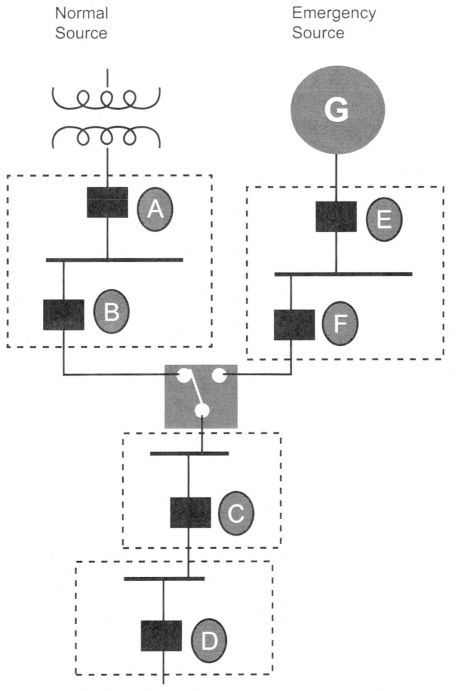
Exception: Selective coordination shall not be required between two overcurrent devices located in series if no loads are connected in parallel with the downstream device.
Informational Note: See Informational Note Figure 708.54(C) for an example of how critical operations power system OCPDs selectively coordinate with all supply-side OCPDs.
OCPD D selectively coordinates with OCPDs C, F, E, B, and A.
OCPD C selectively coordinates with OCPDs F, E, B, and A.
OCPD F selectively coordinates with OCPD E.
OCPD B is not required to selectively coordinate with OCPD A because OCPD B is not a critical operations power system OCPD.
Informational Note Figure 708.54(C) Critical Operations Power System Selective Coordination.
708.64 Emergency Operations Plan.
A facility with a COPS shall have a documented emergency operations plan. The plan shall consider emergency operations and response, recovery, and continuity of operations.
Informational Note: See NFPA 1600-2019, Standard on Continuity, Emergency, and Crisis Management, Section 5.7, which provides guidance for the development and implementation of emergency plans.
Article 710
Stand-Alone Systems
710.1 Scope.
This article covers electric power production systems that operate in island mode not connected to an electric utility or other electric power production and distribution network.
710.6 Equipment Approval.
All power production equipment or systems shall be approved for use in island mode and comply with one of the following:
- Be listed
- Be evaluated for the application and have a field label applied
710.10 Identification of Power Sources.
A permanent plaque, label, or directory shall be installed at a building supplied by a stand-alone system at the power source disconnecting means location, or at an approved readily visible location. The plaque, label, or directory shall denote the location of each power source disconnecting means for the building or be grouped with other plaques or directories for other on-site sources. Where multiple sources supply the building, markings shall comply with 705.10.
710.12 Stand-Alone Inverter Input Circuit Current.
The maximum current shall be the stand-alone continuous inverter input current rating when the inverter is producing rated power at the lowest input voltage.
710.15 General.
Premises wiring systems shall be adequate to meet the requirements of this Code for similar installations supplied by a feeder or service. The wiring on the supply side of the building or structure disconnecting means shall comply with the requirements of this Code, except as modified by 710.15(A) through (G).
(A) Supply Output.
Power supply to premises wiring systems fed by stand-alone or isolated microgrid power sources shall be permitted to have less capacity than the calculated load. The capacity of the sum of all sources of the stand-alone supply shall be equal to or greater than the load posed by the largest single utilization equipment connected to the system. Calculated general lighting loads shall not be considered as a single load.
Informational Note: For general-use loads the system capacity can be calculated using the sum of the capacity of the firm sources, such as generators and ESS inverters. For specialty loads intended to be powered directly from a variable source, the capacity can be calculated using the sum of the variable sources, such as PV or wind inverters, or the combined capacity of both firm and variable sources.
(B) Sizing and Protection.
The circuit conductors between a stand-alone source and a building or structure disconnecting means shall be sized based on the sum of the output ratings of the stand-alone source(s). For three-phase interconnections, the phase loads shall be controlled or balanced to be compatible with specifications of the sum of the power supply capacities.
(C) Single 120-Volt Supply.
Stand-alone and isolated microgrid systems shall be permitted to supply 120 volts to single-phase, 3-wire, 120/240-volt service equipment or distribution panels where there are no 240-volt outlets and where there are no multiwire branch circuits. In all installations, the sum of the ratings of the power sources shall be less than the rating of the neutral bus in the service equipment. This equipment shall be marked with the following words or equivalent:
WARNING:
SINGLE 120-VOLT SUPPLY. DO NOT CONNECT MULTI-
WIRE BRANCH CIRCUITS!.
The warning sign(s) or label(s) shall comply with 110.21(B).
(F) Voltage and Frequency Control.
The stand-alone power sources shall be controlled during operation so that voltage and frequency are supplied within limits compatible with the connected loads.
Article 722
Cables for Power-Limited Circuits and Fault-Managed Power Circuits
722.1 Scope.
This article covers the general requirements for the installation of single- and multiple-conductor cables used in Class 2 and Class 3 power-limited circuits, power-limited fire alarm (PLFA) circuits, and Class 4 fault-managed power circuits.
722.3 Other Articles.
In addition to the requirements of this article, installation of cables shall comply with the articles or sections listed in 722.3(A) through (O). Only those sections of Article 300 referenced in this article shall apply.
(C) Ducts, Plenums, and Other Air-Handling Spaces.
Power-limited circuits installed in ducts, plenums, or other space used for environmental air shall comply with 300.22.
Exception No. 1: Cables selected in accordance with Table 722.135(B) and installed in accordance with 300.22(B), Exception shall be permitted to be installed in ducts specifically fabricated for environmental air.
Exception No. 2: Cables selected in accordance with Table 722.135(B) shall be permitted to be installed in other spaces used for environmental air (plenums).
(D) Cables in Ducts for Dust, Loose Stock, or Vapor Removal.
Section 300.22(A) for wiring systems shall apply.
Exception: Nonconductive optical fiber cables shall be permitted in ducts used for dust, loose stock, or vapor removal.
(H) Vertical Support for Fire-Resistive Cables and Conductors.
Vertical installations of circuit integrity (CI) cables and conductors installed in a raceway or conductors and cables of electrical circuit protective systems and fire resistive-cable systems shall be installed in accordance with 300.19.
(K) Cable Routing Assemblies.
Cables installed in cable routing assemblies shall be selected in accordance with Table 800.154(c), listed in accordance with 800.182, and installed in accordance with 800.110(C)(1)), 800.110(C)(2), and 800.113.
(M) Temperature Limitation of Cables.
The requirements of 310.14(A)(3) on the temperature limitation of conductors shall apply to power-limited circuit cables and fault-managed power cables.
(N) Identification of Equipment Grounding Conductors.
Equipment grounding conductors shall be identified in accordance with 250.119.
Exception: Cables that do not contain an equipment grounding conductor shall be permitted to use a conductor with green insulation, or green insulation with one or more yellow stripes, for other than equipment grounding purposes.
(O) Specific Requirements.
As appropriate, the installation of wires and cables shall also comply with the following:
- Class 2 and Class 3 cables - Part II of Article 725
- Class 4 cables - Part IV of Article 726
- Fire alarm cables - Part III of Article 760
- Optical fiber cables - Part V of Article 770
722.10 Hazardous (Classified) Locations.
Class 4 cables shall be permitted to be used in hazardous (classified) locations where specifically permitted by other articles of this Code.
722.21 Access to Electrical Equipment Behind Panels Designed to Allow Access.
Access to electrical equipment shall not be denied by an accumulation of cables that prevents removal of panels, including suspended ceiling panels.
722.24 Mechanical Execution of Work.
(A) General.
Cables shall be installed in a neat and workmanlike manner. Cables installed exposed on the surface of ceilings and sidewalls shall be supported by the building structure in such a manner that the cable will not be damaged by normal building use. Such cables shall be secured by hardware, including straps, staples, hangers, listed cable ties identified for securement and support, or similar fittings, designed and installed so as not to damage the cable. The installation shall conform to 300.4 and 300.11.
A bushing shall be installed where cables emerge from raceway used for mechanical support or protection in accordance with 300.15(C).
Nonmetallic cable ties and other nonmetallic cable accessories used to secure and support cables in other spaces used for environmental air (plenums) shall be listed as having low smoke and heat release properties in accordance with 300.22(C).
Informational Note No. 1: See NFPA 90A-2021, Standard for the Installation of Air-Conditioning and Ventilating Systems, for discrete combustible components.
Informational Note No. 2: Paint, plaster, cleaners, abrasives, corrosive residues, or other contaminants could result in an undetermined alteration of cable properties.
(B) Support of Cables.
Cables shall not be strapped, taped, or attached by any means to the exterior of any conduit or other raceway as a means of support.
Exception No. 1: Class 2 circuit conductors or cables shall be permitted to be installed as permitted by 300.11(C)(2).
Exception No. 2: Overhead (aerial) spans of optical fiber cables shall be permitted to be attached to the exterior of a raceway-type mast intended for the attachment and support of such cables.
722.25 Abandoned Cables.
The accessible portion of abandoned cables shall be removed. Where cables are identified for future use with a tag, the tag shall be of sufficient durability to withstand the environment involved.
722.31 Safety-Control Equipment.
Where damage to power-limited circuits can result in a failure of safety-control equipment that would introduce a direct fire or life hazard, the power limited circuits shall be installed using Class 1 circuit wiring methods in accordance with 724.46. All conductors of such circuits shall be installed in rigid metal conduit, intermediate metal conduit, rigid nonmetallic conduit, electrical metallic tubing, Type MI cable, or Type MC cable, or be otherwise suitably protected from physical damage.
722.135 Installation of Cables.
(A) Listing.
Cables installed in buildings shall be listed.
(B) Cables in Buildings.
The installation of cables shall comply with Table 722.135(B).
Informational Note No. 1: See NFPA 90A-2021, Standard for the Installation of Air-Conditioning and Ventilating Systems, 4.3.4 and 4.3.11.3.3, for information on fire protection of wiring installed in ducts specifically fabricated for environmental air and other spaces used for environmental air (plenums).
Informational Note No. 2: See 300.21 for firestop requirements for floor penetrations.
Informational Note No. 3: See Chapter 3 for the installation requirements for PLTC cables installed outdoors in cable trays.
Informational Note No. 4: See UL 2024, Cable Routing Assemblies and Communications Raceways, for applicable requirements for plenum, riser, and general-purpose cable routing assemblies and raceways.
(C) Industrial Establishments.
In industrial establishments where the conditions of maintenance and supervision ensure that only qualified persons service the installation, Type PLTC cable shall be permitted in accordance with either of the following:
- Where the cable is not subject to physical damage, Type PLTC cable that complies with the crush and impact requirements of Type MC cable and is identified as Type PITC-ER for such use shall be permitted to be exposed between the cable tray and the utilization equipment or device. The cable shall be continuously supported and protected against physical damage using mechanical protection such as dedicated struts, angles, or channels. The cable shall be supported and secured at intervals not exceeding 1.8 m (6 ft). Where not subject to physical damage, Type PLTC-ER cable shall be permitted to transition between cable trays and between cable trays and utilization equipment or devices for a distance not to exceed 1.8 m (6 ft) without continuous support. The cable shall be mechanically supported where exiting the cable tray to ensure that the minimum bending radius is not exceeded.
- Type PLTC cable, with a metallic sheath or armor in accordance with 722.179(A)(6), shall be permitted to be installed exposed. The cable shall be continuously supported and protected against physical damage using mechanical protection such as dedicated struts, angles, or channels. The cable shall be secured at intervals not exceeding 1.8 m (6 ft).
(D) In Hoistways.
In hoistways, cables shall be installed in rigid metal conduit, rigid nonmetallic conduit, intermediate metal conduit, liquidtight flexible nonmetallic conduit, or electrical metallic tubing. For elevators or similar equipment, these conductors shall be permitted to be installed as provided in 620.21.
(E) Cable Substitutions.
The substitutions for cables listed in Table 722.135(E) shall be permitted. Where substitute cables are installed, the installation requirements of the articles described in 722.3(0) shall also apply. CI cables shall be permitted to be installed to provide 2-hour circuit integrity. See 722.135(F).
Informational Note: See 800.179 for information on Types CMP, CMR, CM, and CMX.
(F) Circuit Integrity (CI) Cable, Fire-Resistive Cable System, or Electrical Circuit Protective System.
CI cable, a fire-resistive cable system, or a listed electrical circuit protective system shall be permitted for use in systems that supply critical circuits to ensure survivability for continued circuit operation for a specified time under fire conditions.
(G) Thermocouple Circuits.
Conductors in Type PLTC cables used for Class 2 thermocouple circuits shall be permitted to be any of the materials used for thermocouple extension wire.
(I) Installation of Circuit Conductors Extending Beyond One Building.
Circuit conductors that extend beyond one building and are run such that they are subject to accidental contact with electric light or power conductors operating over 300 volts to ground, or are exposed to lightning on interbuilding circuits on the same premises, shall comply with the following:
- For other than coaxial conductors, 800.44, 800.53, 800.100, 805.50, 805.93, 805.170(A), and 805.170(B)
- For coaxial conductors, 800.44, 820.93, and 820.100
- The installation requirements of Part I of Article 300
Table 722.135(B) Installation of Listed Cables in Buildings.
| Applications | Cable Type1 | ||||||
|---|---|---|---|---|---|---|---|
| Plenum | Riser | General-Purpose | Limited-Use | Under Carpet | PLTC | ||
| In ducts specifically fabricated for environmental air as described in 300.22(B)2 | Cables in lengths as short as practicable to perform the required function | Y | N | N | N | N | N |
| In metal raceway that complies with 300.22(B) | Y | Y | Y | Y | N | Y | |
| In other spaces used for environmental air (plenums) as described in 300.22(C) | Cables in other spaces used for environmental air | Y | N | N | N | N | N |
| Cables in metal raceway that complies with 300.22(C) | Y | Y | Y | Y | N | Y | |
| Cables in plenum communications raceways | Y | N | N | N | N | N | |
| Cables in plenum cable routing assemblies | Y | N | N | N | N | N | |
| Cables supported by open metal cable trays | Y | N | N | N | N | N | |
| Cables or cables installed in raceways or cable routing assemblies supported by solid bottom metal cable trays with solid metal covers | Y | Y | Y | Y | N | Y | |
| In risers and vertical runs | Cables in vertical runs penetrating one or more floors and in vertical runs in a shaft | Y | Y | N | N | N | N |
| Cables in metal raceways | Y | Y | Y | Y | N | Y | |
| Cables in fireproof shafts | Y | Y | Y | N | N | Y | |
| Cables in plenum communications raceways | Y | Y | N | N | N | N | |
| Cables in plenum cable routing assemblies | Y | Y | N | N | N | N | |
| Cables in riser communications raceways | Y | Y | N | N | N | N | |
| Cables in riser cable routing assemblies | Y | Y | N | N | N | N | |
| Cables in one- and two-family dwellings | Y | Y | Y | Y3 | N | Y | |
| Cables and innerducts installed in metal raceways in a riser having firestops at each floor2 | Cables | Y | Y | Y | Y | N | Y |
| Cables in plenum communications raceways(innerduct) | Y | Y | Y | Y | N | Y | |
| Cables in riser communications raceways (innerduct) | Y | Y | Y | Y | N | Y | |
| Cables in general-purpose communications raceways (innerduct) | Y | Y | Y | Y | N | Y | |
| In fireproof riser shafts having firestops at each floor2 | Cables | Y | Y | Y | N | N | Y |
| Cables in plenum communications raceways or plenum cable routing assemblies | Y | Y | Y | N | N | Y | |
| Cables in riser communications raceways or riser cable routing assemblies | Y | Y | Y | N | N | Y | |
| Cables in general-purpose communications raceways or general-purpose cable routing assemblies | Y | Y | Y | N | N | Y | |
| In cable trays | Outdoors | N | N | N | N | N | Y |
| Cables, or cables in plenum, riser, or general-purpose communications raceways, installed indoors | Y | Y | Y | N | N | Y | |
| In cross-connect arrays | Cables, and cables in plenum, riser, or general-purpose communications raceways or cable routing assemblies | Y | Y | Y | N | N | Y |
| In one-, two-, and multifamily dwellings, and in building locations other than the locations covered above | Cables | Y | Y | Y | Y3 | N | Y |
| Cables in plenum, riser, or general-purpose communications raceways or cable routing assemblies, or raceways recognized in Chapter 3 | Y | Y | Y | Y | N | Y | |
| Cables in nonconcealed spaces | Y | Y | Y | Y4 | Y | Y | |
| Under carpet, floor covering, modular flooring, and planks | N | N | N | N | Y | N | |
1"N" indicates that the cable type shall not be installed in the application. "Y" indicates that the cable type shall be permitted to be installed in the application, subject to any limitations described in this article or the articles described in 722.3(O).
2In 300.22(B), cables shall be permitted in ducts specifically fabricated for environmental air only if directly associated with the air distribution system.
3Limited-use cable shall be permitted to be installed only in one-, two-, and multifamily dwellings and only if the cable is smaller in diameter than 6.35 mm (0.25 in.).
4The exposed length of cable shall not exceed 3.05 m (10 ft).
Table 722.135(E) Cable Substitutions.
| Cable Type | Permitted Substitutions |
|---|---|
| CL3P | CMP |
| CL2P | CMP, CL3P |
| CL3R | CMP, CL3P, CMR |
| CL2R | CMP, CL3P, CL2P, CMR, CL3R |
| PLTC | None |
| CL3 | CMP, CL3P, CMR, CL3R, CMG, CM, PLTC |
| CL2 | CMP, CL3P, CL2P, CMR, CL3R, CL2R, CMG, CM, PLTC, CL3 |
| CL3X | CMP, CL3P, CMR, CL3R, CMG, CM, PLTC, CL3, CMX |
| CL2X | CMP, CL3P, CL2P, CMR, CL3R, CL2R, CMG, CM, PLTC, CL3, CL2, CMX, CL3X |
| FPLP | CMP |
| FPLR | CMP, FPLP, CMR |
| FPL | CMP, FPLP, CMR, FPLR, CMG, CM |
| OFNP | None |
| OFCP | OFNP |
| OFNR | OFNP |
| OFCR | OFNP, OFCP, OFNR |
| OFNG, OFN | OFNP, OFNR |
| OFCG, OFC | OFNP, OFCP, OFNR, OFCR, OFNG, OFN |
| CMUC | None |
722.179 Listing and Marking of Cables.
Cables installed in buildings shall be listed in accordance with 722.179(A) and marked in accordance with 722.179(B), and they shall be permitted to be marked in accordance with 722.179(C).
Exception: Optical fiber cables that are installed in compliance with 770.48 shall not be required to be listed.
(A) Listing of Cables.
Cables installed as wiring methods within buildings shall be listed as resistant to the spread of fire and other criteria in accordance with 722.179(A)(1) through (A) (16).
Informational Note No. 1: See UL 13, Standard for Power-Limited Circuit Cables, for applicable requirements for listing of Class 2 and Class 3 cable and power-limited tray cable (PLTC).
Informational Note No. 2: See UL 1424, Cables for Power-Limited Fire-Alarm Circuits, for applicable requirements for listing of power-limited fire alarm cable.
Informational Note No. 3: See UL 1651, Optical Fiber Cable, for applicable requirements for listing of optical fiber cable.
Informational Note No. 4: See UL 1400-2, Outline for Fault-Managed Power Systems - Part 2: Requirements for Class 4 Cables, for applicable requirements for listing of Class 4 cable.
(1) Plenum Cable.
Plenum cable shall be listed as suitable for use in ducts, plenums, and other space for environmental air and shall be listed as having adequate fire-resistant and low-smoke producing characteristics. Refer to Table 722.179(B) for plenum cable types.
Informational Note: See NFPA 262-2019, Standard Method of Test for Flame Travel and Smoke of Wires and Cables for Use in Air-Handling Spaces, for the test method used to determine that a cable is low-smoke producing and fire resistant, exhibiting a maximum peak optical density of 0.50 or less, an average optical density of 0.15 or less, and a maximum flame spread distance of 1.52 m (5 ft) or less.
(2) Riser Cable.
Riser cable shall be listed as suitable for use in a vertical run in a shaft or from floor to floor and shall be listed as having fire-resistant characteristics capable of preventing the carrying of fire from floor to floor.
(3) General-Purpose Cable.
General-purpose cable shall be listed as resistant to the spread of fire and as suitable for general-purpose use, except for use in risers, ducts, plenums, and other space used for environmental air.
Informational Note: See UL 2556, Wire and Cable lest Methods, for defining resistant to the spread of fire. One method is to demonstrate that the cables do not spread fire to the top of the tray in the UL Flame Exposure, Vertical Tray Flame Test. The smoke measurements in the test method are not applicable.
A method of defining resistant to the spread of fire is for the damage (char length) not to exceed 1.5 m (4 ft 11 in.) when performing the FT4 Vertical Flame Test.
(4) Alternative General-Purpose Cable.
(5) Limited-Use Cable.
(6) Type PLTC.
Type PLTC nonmetallic-sheathed, power-limited tray cable shall be listed as being suitable for cable trays, resistant to the spread of fire, and sunlight- and moisture-resistant. Type PLTC cable used in a wet location shall be listed for use in wet locations and marked "wet" or "wet location."
Informational Note: See ANSI/UL 1685-2010, Standard for Safety for Vertical-Tray Fire-Propagation and Smoke-Release Test for Electrical and Optical-Fiber Cables, for the UL flame exposure, vertical tray flame test that is used to determine resistance to the spread of fire when cables do not spread fire to the top of the tray. The smoke measurements in the test method are not applicable.
(7) Circuit Integrity (CI) Cable, Fire-Resistive Cable System, or Electrical Circuit Protective System.
Cables that are used for survivability of critical circuits under fire conditions shall comply with either 722.179(A)(7)(a), (A)(7)(b), or (A)(7)(c).
Informational Note: See NFPA 72, National Fire Alarm and Signaling Code, 12.4.3 and 12.4.4, for additional information on fire alarm CI cable, fire-resistive cable systems, or electrical circuit protective systems used for fire alarm circuits to comply with the survivability requirements to maintain the circuit's electrical function during fire conditions for a defined period of time.
- CI Cables. CI cables of the types specified in 722.179(A)(1), (A)(2), (A)(3), (A)(4), and (A)(6) and used for survivability of critical circuits shall be marked with the additional classification using the suffix "CI" To maintain its listed fire-resistive rating, CI cable shall only be installed in free air in accordance with 722.24(C). CI cables shall only be permitted to be installed in a raceway where specifically listed and marked as part of a fire-resistive cable system as covered in 722.179(A)(7)(b).Informational Note: See UL 2196, Fire Test for Circuit Integrity of Fire-Resistive Power, Instrumentation, Control and Data Cables, and UL 1425, Cables for Non—Power-Limited Fire-Alarm Circuits, for information on establishing a rating for CI cable. The UL Guide Information for Nonpower-limited Fire Alarm Circuits (HNHT) contains information to identify the cable and its installation limitations to maintain the fire-resistive rating.
- Fire-Resistive Cables. Fire-resistive cables of the types specified in 722.179(A)(1), (A)(2), (A)(3), (A)(4), (A)(6), and (A)(7)(a) that are part of a fire-resistive cable system shall be identified with the system identifier and hourly rating marked on the protectant or the smallest unit container and installed in accordance with the listing of the system.Informational Note: See UL 2196, Fire Test for Circuit Integrity of Fire-Resistive Power, Instrumentation, Control and Data Cables, for information on establishing a rating for a fire-resistive cable system. The UL Guide Information for Electrical Circuit Integrity Systems (FHIT) contains information to identify the system and its installation limitations to maintain a minimum fire-resistive rating.
- Electrical Circuit Protective System. Protectants for cables of the types specified in 722.179(A)(1), (A)(2), (A)(3), (A)(4), and (A)(6) that are part of an electrical circuit protective system shall be identified with the protective system identifier and hourly rating marked on the protectant or the smallest unit container and installed in accordance with the listing of the protective system.
Informational Note: See UL 1724, Fire Tests for Electrical Circuit Protective Systems, for information on establishing a rating for an electrical circuit protective system. The UL Guide Information for Electrical Circuit Integrity Systems (FHIT) contains information to identify the system and its installation limitations to maintain the fire-resistive rating.
(8) Class 3 Single Conductors.
Class 3 single conductors used as other wiring within buildings shall be listed Type CL3 and shall not be smaller than 18 AWG.
Informational Note: See ANSI/UL 1685-2010, Standard for Safety for Vertical-Tray Fire-Propagation and Smoke-Release Test for Electrical and Optical-Fiber Cables, for the UL flame exposure, vertical tray flame test that is used to determine resistance to the spread of fire when cables do not spread fire to the top of the tray. The smoke measurements in the test method are not applicable.
(9) Limited Power (LP) Cable.
Class 2 and Class 3 LP cables shall be listed as suitable for carrying power and data up to a specified current limit for each conductor without exceeding the temperature rating of the cable. The cables shall be marked with the suffix "-LP (XXA)" where XXA designates the current limit in amperes per conductor.
Informational Note: An example of the marking on 23 AWG, 4-pair, Class 2 cable rated 75°C with an LP current rating of 0.6 amperes per conductor is "CL2-LP (0.6A) 75°C 23 AWG 4-pair."
Field-Assembled Optical Fiber Cables.
Field-assembled optical fiber cable shall comply with 722.179(A) (12) (a) through (d).
- The specific combination of jacket and optical fibers intended to be installed as a field-assembled optical fiber cable shall be one of the types in 722.179(A)(1), (A)(2), or (A)(3) and shall be marked in accordance with Table 179(B).
- The jacket of a field-assembled optical fiber cable shall have a surface marking indicating the specific optical fibers with which it is identified for use.
- The optical fibers shall have a permanent marking, such as a marker tape, indicating the jacket with which they are identified for use.
- The jacket without fibers shall meet the listing requirements for communications raceways in 800.182(A), (B), or (C) in accordance with the cable marking.
Cables Containing Optical Fibers.
Composite optical fiber cables shall be listed as electrical cables based on the type of electrical conductors.
Power-Limited Fire Alarm (PLFA) Cables.
PFLA cables shall comply with 722.179(A) (15) (a) through (A)(15)(d).
- Conductors for cables, other than coaxial cables, shall be solid or stranded copper. Coaxial cables shall be permitted to use 30 percent conductivity copper-covered steel center conductor wire.
- The size of conductors in a multiconductor cable shall not be smaller than 26 AWG. Single conductors shall not be smaller than 18 AWG. Conductors of 26 AWG shall be permitted only where spliced with a connector listed as suitable for 26 AWG to 24 AWG or larger conductors that are terminated on equipment or where the 26 AWG conductors are terminated on equipment listed as suitable for 26 AWG conductors.
- Cables shall have a voltage rating of not less than 300 volts.
- Cables shall have a temperature rating of not less than 60°C (140°F).
Class 4 Cable Construction.
Sizes.
Conductors of sizes not smaller than 24 AWG shall be permitted to be used.
Insulation.
Insulation on conductors shall be rated not less than 450 volts dc.
Temperature Rating.
Cables shall have a temperature rating of not less than 60°C (140°F).
Cabling.
Cables shall comply with any requirements provided in the listing of the system.
Informational Note: See UL 1400-1, Outline for Fault-Managed Power Distribution Technologies - Part 1: General Requirements, for information on determining applicable requirements for the listing of Class 4 power systems. Excessive cable lengths can result in higher capacitance which could affect the safety of the circuit.
(B) Marking.
Cables shall be durably marked on the surface in accordance with the following:
- The AWG size or circular mil area shall be repeated at intervals not exceeding 610 mm (24 in.).
- All other markings shall be repeated at intervals not exceeding 1.0 m (40 in.).
- The proper type designation for the type of cable shall be marked in accordance with Table 722.179(B).
- The manufacturer's name, trademark, or other distinctive marking by which the organization responsible for the product can be readily identified shall be marked.
- The AWG size or circular mil area shall be marked.
- The temperature rating for a temperature rating exceeding 60°C (140°F) shall be marked.Informational Note No. 2: A minimum temperature rating of 60°C is assumed for cables not marked with a temperature rating.
- Voltage ratings shall not be marked on the cables.
Exception: Voltage markings shall be permitted where the cable has multiple listings and a voltage marking is required for one or more of the listings.
Informational Note No. 3: Voltage markings on cables could be misinterpreted to suggest that the cables may be suitable for Class 1 electric light and power applications.
Informational Note No. 4: Cable types are listed in descending order of tire resistance rating.
(C) Optional Markings.
Cables shall be permitted to be surface marked to indicate special characteristics of the cable materials.
Informational Note No. 1: Examples of these characteristics include, but are not limited to, limited smoke, halogen free, low smoke and halogen free, and sunlight resistant.
Informational Note No. 2: Some examples of optional markings are STI to indicate limited smoke characteristics. See UL 2556, Wire and Cable Test Methods; HF to indicate halogen free. See in UL 2885, Outline of Investigation for Acid Gas, Acidity and Conductivity of Combusted Materials; and LSHF to indicate halogen free and low-smoke characteristics. See IEC 61034-2, Measurement of smoke density of cables burning under defined conditions - Part 2: Test procedure and requirements.
Table 722.179(B) Cable Type Markings.
| Cable Type | Cable Marking |
|---|---|
| Class 4 plenum cable | CL4P |
| Class 3 plenum cable | CL3P |
| Class 2 plenum cable | CL2P |
| Power-limited fire alarm plenum cable | FPLP |
| Nonconductive optical fiber plenum cable | OFNP |
| Conductive optical fiber plenum cable | OFCP |
| Class 4 riser cable | CL4R |
| Class 3 riser cable | CL3R |
| Class 2 riser cable | CL2R |
| Power-limited fire alarm riser cable | FPLR |
| Nonconductive optical fiber riser cable | OFNR |
| Conductive optical fiber riser cable | OFCR |
| Class 4 general-purpose cable | CL4 |
| Class 3 general-purpose cable | CL3 |
| Class 2 general-purpose cable | CL2 |
| Power-limited fire alarm cable | FPL |
| Nonconductive general-purpose optical fiber cable | OFN |
| Conductive general-purpose optical fiber cable | OFC |
| Alternative nonconductive general-purpose optical fiber cable | OFNG |
| Alternative conductive general-purpose optical fiber cable | OFCG |
| Class 3 cable - limited use | CL3X |
| Class 2 cable - limited use | CL2X |
| Undercarpet cable | CMUC |
Note: All types of CL2, CL3, and FPL cables containing optical fibers are provided with the suffix "-OF."
Article 724
Class 1 Power-Limited Circuits and Class 1 Power-Limited Remote-Control and Signaling Circuits
724.1 Scope.
This article covers Class 1 circuits, including power-limited Class 1 remote-control and signaling circuits, that are not an integral part of a device or utilization equipment.
724.3 Other Articles.
In addition to the requirements of this article, circuits and equipment shall comply with 724.3(A) through (J).
(D) Hazardous (Classified) Locations.
Class 1 circuits shall not be installed in any hazardous (classified) locations except as permitted by other articles of this Code.
(G) Vertical Support for Fire-Rated Cables and Conductors.
Vertical installations of circuit integrity (CI) cables and conductors installed in a raceway or conductors and cables of electrical circuit protective systems shall comply with 300.19.
724.24 Mechanical Execution of Work.
Class 1 circuits shall be installed in a neat and workmanlike manner. Cables and conductors installed exposed on the surfaces of ceilings and sidewalls shall be supported by the building structure such that the cable will not be damaged by normal building use. Such cables shall be supported by straps, staples, hangers, cable ties, or similar fittings that are designed and installed to not damage the cable. The installation shall also comply with the requirements of 300.4 and 300.11.
Informational Note: Paint, plaster, cleaners, abrasives, corrosive residues, or other contaminants can result in an undetermined alteration of Class 1 cable properties.
724.31 Safety-Control Equipment.
If controlling safety-control equipment, Class 1 circuits shall be provided with physical protection if the failure of such equipment to operate introduces a direct fire or life hazard. All conductors of such circuits shall be installed in rigid metal conduit, intermediate metal conduit, rigid nonmetallic conduit, electrical metallic tubing, Type MI cable, or Type MC cable, or be otherwise suitably protected from physical damage.
724.40 Class 1 Circuits.
Class 1 circuits shall be supplied from a source with a rated output of not more than 30 volts and 1000 volt-amperes.
(A) Class 1 Transformers.
Transformers shall be permitted to supply Class 1 circuits.
Informational Note: See Parts I and II of Article 450 for information on transformers used to supply a Class 1 circuit.
(B) Other Class 1 Power Sources.
Power sources other than transformers shall be protected by overcurrent devices rated at not more than 167 percent of the volt-ampere rating of the source divided by the rated voltage. The overcurrent devices shall not be interchangeable with overcurrent devices of higher ratings. The overcurrent device shall be permitted to be an integral part of the power supply.
To comply with the 1000 volt-ampere limitation of 724.40, the maximum output (VAmax) of power sources other than transformers shall be limited to 2500 volt-amperes, and the product of the maximum current (Imax) and maximum voltage (Vmax) shall not exceed 10,000 volt-amperes. These ratings shall be determined with any overcurrent-protective device bypassed.
VAmax is the maximum volt-ampere output after one minute of operation regardless of load and with overcurrent protection bypassed, if used. Current-limiting impedance shall not be bypassed when determining VAmax.
Imax is the maximum output current under any noncapacitive load, including short circuit, and with overcurrent protection bypassed, if used. Current-limiting impedance should not be bypassed when determining Where a current-limiting impedance listed for the purpose or as part of a listed product is used in combination with a stored energy source, such as a storage battery, to limit the output current, Imax limits apply after 5 seconds.
Vmax is the maximum output voltage regardless of load with rated input applied.
724.43 Class 1 Circuit Overcurrent Protection.
Overcurrent protection for conductors 14 AWG and larger shall be provided in accordance with the conductor ampacity, without applying the ampacity adjustment and correction factors specified in 310.15 to the ampacity calculation. Overcurrent protection shall not exceed 7 amperes for 18 AWG conductors and 10 amperes for 16 AWG.
Exception: Where other articles of this Code permit or require other overcurrent protection.
724.45 Class 1 Circuit Overcurrent Device Location.
(A) Point of Supply.
Overcurrent devices shall be located at the point where the conductor to be protected receives its supply.
(B) Feeder Taps.
Class 1 circuit conductors shall be permitted to be tapped, without overcurrent protection at the tap, where the overcurrent device protecting the circuit conductor is sized to protect the tap conductor.
(C) Branch-Circuit Taps.
Class 1 circuit conductors 14 AWG and larger that are tapped from the load side of the overcurrent protective device(s) of a controlled light and power circuit shall require only short-circuit and ground-fault protection and shall be permitted to be protected by the branch-circuit overcurrent protective device(s) where the rating of the protective device(s) is not more than 300 percent of the ampacity of the Class 1 circuit conductor.
(D) Primary Side of Transformer.
Class 1 circuit conductors supplied by the secondary of a single-phase transformer having only a 2-wire (single-voltage) secondary shall be permitted to be protected by overcurrent protection provided on the primary side of the transformer if the protection is in accordance with 450.3 and does not exceed the value determined by multiplying the secondary conductor ampacity by the secondary-to-primary transformer voltage ratio. Transformer secondary conductors other than 2-wire shall not be considered to be protected by the primary overcurrent protection.
(E) Input Side of Electronic Power Source.
Class 1 circuit conductors supplied by the output of a single-phase, listed electronic power source other than a transformer having only a 2-wire (single-voltage) output for connection to Class 1 circuits shall be permitted to be protected by overcurrent protection provided on the input side of the electronic power source if the protection does not exceed the value determined by multiplying the Class 1 circuit conductor ampacity by the output-to-input voltage ratio. Electronic power source outputs other than 2-wire (single voltage) shall not be considered to be protected by the primary overcurrent protection.
724.46 Class 1 Circuit Wiring Methods.
Class 1 circuits shall be installed in accordance with 300.2 through 300.26.
Exception No. 1: The requirements of 724.48 through 724.51 shall be permitted to apply in installations of Class 1 circuits.
Exception No. 2: Methods permitted or required by other articles of this Code shall apply to installations of Class 1 circuits.
724.48 Conductors of Different Circuits in the Same Cable, Cable Tray, Enclosure, or Raceway.
Class 1 circuits shall be permitted to be installed with other circuits as specified in 724.48(A) and (B).
(A) Two or More Class 1 Circuits.
Class 1 circuits shall be permitted to occupy the same cable, cable tray, enclosure, or raceway regardless of whether the individual circuits are alternating current or direct current if all conductors are insulated for the maximum voltage of any conductor in the cable, cable tray, enclosure, or raceway.
(B) Class 1 Circuits With Power-Supply Circuits.
Class 1 circuits shall be permitted to be installed with power-supply conductors as specified in 724.48(B)(1) through (B)(4).
(1) In Cables, Enclosures, or Raceways.
Class 1 circuits and power-supply circuits shall be permitted to occupy the same cable, enclosure, or raceway without a barrier only where the equipment powered is functionally associated. Class 1 circuits shall be permitted to be installed together with the conductors of electric light, power, non-power-limited fire alarm systems, and medium-power network-powered broadband communications circuits where separated by a barrier.
(2) In Factory- or Field-Assembled Control Centers.
Class 1 circuits and power-supply circuits shall be permitted to be installed in factory- or field-assembled control centers.
(3) In Manholes.
Class 1 circuits and power-supply circuits shall be permitted to be installed as underground conductors in manholes in accordance with one of the following:
- The power-supply or Class 1 circuit conductors are in metal-enclosed cable or Type UF cable.
- The conductors are permanently separated from power-supply conductors by continuous firmly fixed non-conductors, such as flexible tubing, in addition to insulation on the wire.
- The conductors are permanently and effectively separated from power-supply conductors and securely fastened to racks, insulators, or other approved supports.
(4) In Cable Trays.
Installations in cable trays shall comply with the requirements of one of the following:
- Class 1 circuit conductors and power-supply conductors not functionally associated with the Class 1 circuit conductors shall be separated by a solid fixed barrier of a material compatible with the cable tray.
- Class 1 circuit conductors and power-supply conductors not functionally associated with the Class 1 circuit conductors shall be permitted to be installed in a cable tray without barriers where all of the conductors are installed with separate multiconductor Type AC, Type MC, Type MI, or Type TC cables and all the conductors in the cables are insulated at 600 volts or greater.
724.49 Class 1 Circuit Conductors.
(A) Sizes and Use.
Conductors that are 18 AWG and 16 AWG shall be permitted to be used if they supply loads that do not exceed the ampacities specified in 402.5 and are installed in a raceway, an approved enclosure, or a listed cable. Conductors larger than 16 AWG shall not supply loads greater than the ampacities specified in 310.14. Flexible cords shall comply with the requirements of Article 400.
(B) Insulation.
Insulation on conductors shall be rated for the system voltage and not less than 600 volts. Conductors larger than 16 AWG shall comply with the requirements of Article 310. Conductors that are 18 AWG and 16 AWG shall be Type FFH-2, Type KF-2, Type KFF-2, Type PAF, Type PAFF, Type PF, Type PFF, Type PGF, Type PGFF, Type PTF, Type PTFF, Type RFH-2, Type RFHH-2, Type RFHH-3, Type SF-2, SFF-2, Type TF, Type TFF, Type TFFN, Type TFN, Type ZF, or Type ZFF. Conductors with other types and thicknesses of insulation shall be permitted if listed for Class 1 circuit use.
724.51 Number of Conductors in Cable Trays and Raceways, and Ampacity Adjustment.
(A) Class 1 Circuit Conductors.
Where only Class 1 circuit conductors are in a raceway, the number of conductors shall be determined in accordance with 300.17. The ampacity adjustment factors specified in 310.15(C)(1) shall apply only if such conductors carry continuous loads in excess of 10 percent of the ampacity of each conductor.
(B) Power-Supply Conductors and Class 1 Circuit Conductors.
Where power-supply conductors and Class 1 circuit conductors are permitted in a raceway in accordance with 724.48, the number of conductors shall be determined in accordance with 300.17. The ampacity adjustment factors specified in 310.15(C)(1) shall apply as follows:
- To all conductors where the Class 1 circuit conductors carry continuous loads in excess of 10 percent of the ampacity of each conductor and where the total number of conductors is more than three
- To the power-supply conductors only, where the Class 1 circuit conductors do not carry continuous loads in excess of 10 percent of the ampacity of each conductor and where the number of power-supply conductors is more than three
(C) Class 1 Circuit Conductors in Cable Trays.
Where Class 1 circuit conductors are installed in cable trays, they shall comply with the requirements of 392.22 and 392.80(A).
724.52 Circuits Extending Beyond One Building.
Class 1 circuits that extend aerially beyond one building shall also meet the requirements of Part I of Article 225.
Article 725
Class 2 and Class 3 Power-Limited Circuits
725.1 Scope.
This article covers power-limited circuits, including power-limited remote-control and signaling circuits, that are not an integral part of a device or of utilization equipment.
Informational Note No. 1: The circuits described herein are characterized by usage and electrical power limitations that differentiate them from electric light and power circuits; therefore, alternative requirements are given regarding minimum wire sizes, ampacity adjustment and correction factors, overcurrent protection, insulation requirements, and wiring methods and materials.
725.3 Other Articles.
In addition to the requirements of this article, circuits and equipment shall comply with the articles or sections listed in 725.3(A) through (E). Only those sections of Article 300 referenced in this article shall apply to Class 2 and Class 3 circuits.
(C) Motor Control Circuits.
Motor control circuits tapped from the load side of the motor branch-circuit protective device(s) as specified in 430.72(A) shall comply with Part IV of Article 430.
(E) Cables for Class 2 and Class 3 Circuits.
The listing and installation of cables for Class 2 and Class 3 circuits shall comply with Part I and Part II of Article 722.
725.31 Safety-Control Equipment.
Where damage to power-limited circuits can result in a failure of safety-control equipment that would introduce a direct fire or life hazard, the power-limited circuits shall be installed in accordance with 724.31. Room thermostats, water temperature regulating devices, and similar controls used in conjunction with electrically controlled household heating and air conditioning shall not be considered safety-control equipment.
725.60 Power Sources for Class 2 and Class 3 Circuits.
(A) Power Source.
The power source for a Class 2 or a Class 3 circuit shall be as follows: 
Informational Note No. 1: Informational Note Figure 725.60 illustrates the relationships between Class 2 or Class 3 power sources, their supply, and the Class 2 or Class 3 circuits.
Informational Note No. 2: See Chapter 9, Table 11(A) and Table 11(B), for requirements for listed Class 2 and Class 3 power sources.
Informational Note Figure 725.60 Class 2 and Class 3 Circuits..
- A listed Class 2 or Class 3 transformer
- A listed Class 2 or Class 3 power supply
- Other listed equipment marked to identify the Class 2 or Class 3 power sourceException No. 1 to (3): Thermocouples shall not require listing as a Class 2 power source.Exception No. 2 to (3): Limited power circuits of listed equipment where these circuits have energy levels rated at or below the limits established in Chapter 9, Table 11(A) and Table 11(B).Informational Note No. 3: Examples of other listed equipment are as follows:
- A circuit card listed for use as a Class 2 or Class 3 power source where used as part of a listed assembly
- A current-limiting impedance, listed for the purpose, or part of a listed product, used in conjunction with a non-power-limited transformer or a stored energy source, for example, storage battery, to limit the output current
- A thermocouple
- Limited voltage/current or limited impedance secondary communications circuits of listed industrial control equipment
- Listed audio/video, information technology (computer), communications, and industrial equipment limited-power circuitsInformational Note No. 4: One way to determine applicable requirements for listing of information technology (computer) equipment is to refer to UL 60950-1-2011, Standard for Safely of Information Technology Equipment. Another way to determine applicable requirements for listing of audio/video, information technology, and communications equipment is to refer to UL 62368-1-2014, Safety of audio/video, information and communication technology equipment. Typically such circuits are used to interconnect data circuits for the purpose of exchanging information data. One way to determine applicable requirements for listing of industrial equipment is to refer to UL 61010-2-201, Safety requirements for electrical equipment for measurement, control, and laboratory use - Part 2-201: Particular requirements for control equipment, and/or UL 61800-5-1, Adjustable speed electrical power drive systems - Part 5-1: Safety requirements - Electrical, thermal and energy.
- A battery source or battery source system that is listed and identified as Class 2
(B) Interconnection of Power Sources.
Class 2 or Class 3 power sources shall not have the output connections paralleled or otherwise interconnected unless listed for such interconnection.
(C) Marking.
The equipment supplying the circuits shall be durably marked where plainly visible to indicate each circuit that is a Class 2 or Class 3 circuit. The power sources for limited power circuits in 725.60(A)(3), limited power circuits for listed audio/video equipment, listed information technology equipment, listed communications equipment, and listed industrial equipment in 725.60(A)(4) shall have a label indicating the maximum voltage and rated current output per conductor for each connection point on the power source. Where multiple connection points have the same rating, a single label shall be permitted to be used.
Informational Note No. 1: Rated current for power sources covered in 725.144 is the output current per conductor the power source is designed to deliver to an operational load at normal operating conditions, as declared by the manufacturer.
Informational Note No. 2: An example of a label is "52V @ 0.433A, 57V MAX" for an IEEE 802.3 compliant Class 8 power source.
725.127 Wiring Methods on Supply Side of the Class 2 or Class 3 Power Source.
Conductors and equipment on the supply side of the power source shall be installed in accordance with the appropriate requirements of Chapters 1 through 4.
Exception: The input leads of a transformer or other power source supplying Class 2 and Class 3 circuits shall be permitted to be smaller than 14 AWG but not smaller than 18 AWG if they are protected by an overcurrent device rated not over 20 amperes, are not over 305 mm (12 in.) long, and have insulation that complies with 724.49(B).
725.130 Wiring Methods and Materials on Load Side of the Class 2 or Class 3 Power Source.
Class 2 and Class 3 circuits on the load side of the power source shall be permitted to be installed using wiring methods and materials in accordance with 725.130(A), (B), or a combination of both. Parts I and II of Article 722 shall apply.
(A) Class 1 Wiring Methods and Materials.
Use of Class 1 wiring methods for Class 2 and Class 3 circuits shall be permitted. Separation from electric light, power, Class 1, non-power-limited fire alarm circuit conductors, and medium-power network-powered broadband communications cables shall comply with 725.136.
Exception: The ampacity adjustment factors given in 310.15(C)(1) shall not apply.
(B) Class 2 and Class 3 Wiring Methods and Materials.
Conductors on the load side of the power source shall be insulated in accordance with 722.179 and be installed in accordance with 722.135 and 725.136 through 725.144.
Exception No. 2: Other wiring methods and materials installed in accordance with 725.3 shall be permitted to extend or replace the conductors and cables described in 722.179(A) and permitted by 725.130(B).
Exception No. 3: Bare Class 2 conductors shall be permitted as part of a listed intrusion protection system where installed in accordance with the listing instructions for the system.
725.136 Separation From Electric Light, Power, Class 1, Non-Power-Limited Fire Alarm Circuit Conductors, and Medium-Power Network-Powered Broadband Communications Cables.
(A) General.
Cables and conductors of Class 2 and Class 3 circuits shall not be placed in any cable, cable tray, compartment, enclosure, manhole, outlet box, device box, raceway, or similar fitting with conductors of electric light, power, Class 1, non—power-limited fire alarm circuits, and medium-power network-powered broadband communications circuits unless permitted by 725.136(B) through (I).
(B) Separated by Barriers.
Class 2 and Class 3 circuits shall be permitted to be installed together with the conductors of electric light, power, Class 1, non—power-limited fire alarm, and medium-power network-powered broadband communications circuits where they are separated by a barrier.
(C) Raceways Within Enclosures.
In enclosures, Class 2 and Class 3 circuits shall be permitted to be installed in a raceway to separate them from Class 1, non—power-limited fire alarm, and medium-power network-powered broadband communications circuits.
(D) Associated Systems Within Enclosures.
Class 2 and Class 3 circuit conductors in compartments, enclosures, device boxes, outlet boxes, or similar fittings shall be permitted to be installed with electric light, power, Class 1, non—power-limited fire alarm, and medium-power network-powered broadband communications circuits where they are introduced solely to connect the equipment connected to Class 2 and Class 3 circuits, and where one of the following applies:
- The electric light, power, Class 1, non—power-limited fire alarm, and medium-power network-powered broadband communications circuit conductors are routed to maintain a minimum of 6 mm (0.25 in.) separation from the conductors and cables of Class 2 and Class 3 circuits.
- The circuit conductors operate at 150 volts or less to ground and comply with one of the following:
- The Class 2 and Class 3 circuits are installed using Type CL3, Type CL3R, or Type CL3P or permitted substitute cables if these Class 3 cable conductors extending beyond the jacket are separated by a minimum of 6 mm (0.25 in.) or by a nonconductive sleeve or nonconductive barrier from all other conductors.
- The Class 2 and Class 3 circuit conductors are installed as a Class 1 circuit in accordance with 724.40.
(E) Enclosures With Single Opening.
Class 2 and Class 3 circuit conductors entering compartments, enclosures, device boxes, outlet boxes, or similar fittings shall be permitted to be installed with Class 1, non—power-limited fire alarm, and medium-power network-powered broadband communications circuits where they are introduced solely to connect the equipment connected to Class 2 and Class 3 circuits. Where Class 2 and Class 3 circuit conductors must enter an enclosure that is provided with a single opening, they shall be permitted to enter through a single fitting (such as a tee) if the conductors are separated from the conductors of the other circuits by a continuous and firmly fixed nonconductor, such as flexible tubing.
(F) Manholes.
Underground Class 2 and Class 3 circuit conductors in a manhole shall be permitted to be installed with Class 1, non—power-limited fire alarm, and medium-power network-powered broadband communications circuits where one of the following conditions is met:
- The electric light, power, Class 1, non—power-limited fire alarm, and medium-power network-powered broadband communications circuit conductors are in a metal-enclosed cable or Type UF cable.
- The Class 2 and Class 3 circuit conductors are permanently and effectively separated from the conductors of other circuits by a continuous and firmly fixed nonconductor, such as flexible tubing, in addition to the insulation or covering on the wire.
- The Class 2 and Class 3 circuit conductors are permanently and effectively separated from conductors of the other circuits and securely fastened to racks, insulators, or other approved supports.
(G) Cable Trays.
Class 2 and Class 3 circuit conductors shall be permitted to be installed in cable trays where the conductors of the electric light, Class 1, and non—power-limited fire alarm circuits are separated by a solid fixed barrier of a material compatible with the cable tray or where the Class 2 or Class 3 circuits are installed in Type MC cable.
(H) Where Protected.
Class 2 and Class 3 circuits shall be permitted to be installed together with the conductors of electric light, power, Class 1, non—power-limited fire alarm, and medium-power network-powered broadband communications circuits where they are installed using Class 1 wiring methods in accordance with 724.46 and where they are protected by an approved raceway.
(I) Other Applications.
For other applications, conductors of Class 2 and Class 3 circuits shall be separated by at least 50 mm (2 in.) from conductors of any electric light, power, Class 1, non—power-limited fire alarm, or medium-power network-powered broadband communications circuits unless one of the following conditions is met:
- Either all of the electric light, power, Class 1, non—power-limited fire alarm, and medium-power network-powered broadband communications circuit conductors or all of the Class 2 and Class 3 circuit conductors are in a raceway or in metal-sheathed, metal-clad, nonmetallic-sheathed, Type TC, or Type UF cables.
- All of the electric light, power, Class 1, non—power-limited fire alarm, and medium-power network-powered broadband communications circuit conductors are permanently separated from all of the Class 2 and Class 3 circuit conductors by a continuous and firmly fixed nonconductor, such as porcelain tubes or flexible tubing, in addition to the insulation on the conductors.
725.139 Installation of Conductors of Different Circuits in the Same Cable, Enclosure, Cable Tray, Raceway, or Cable Routing Assembly.
(A) Two or More Class 2 Circuits.
Conductors of two or more Class 2 circuits shall be permitted within the same cable, enclosure, raceway, or cable routing assembly.
(B) Two or More Class 3 Circuits.
Conductors of two or more Class 3 circuits shall be permitted within the same cable, enclosure, raceway, or cable routing assembly.
(C) Class 2 Circuits With Class 3 Circuits.
Conductors of one or more Class 2 circuits shall be permitted within the same cable, enclosure, raceway, or cable routing assembly with conductors of Class 3 circuits if the insulation of the Class 2 circuit conductors in the cable, enclosure, raceway, or cable routing assembly is at least that required for Class 3 circuits.
(D) Class 2 and Class 3 Circuits With Communications Circuits.
(1) Communications Cables.
Conductors of one or more Class 2 or Class 3 circuits shall be permitted in the same cable with conductors of communications circuits if the cable is a listed communications cable installed in accordance with Part V of Article 800. The cables shall be listed as communications cables.
(2) Composite Cables.
Cables constructed of individually listed Class 2, Class 3, and communications cables under a common jacket shall be permitted to be classified as communications cables. The fire resistance rating of the composite cable shall be determined by the performance of the composite cable.
(E) Class 2 or Class 3 Cables With Other Circuit Cables.
Jacketed cables of Class 2 or Class 3 circuits shall be permitted in the same enclosure, cable tray, raceway, or cable routing assembly with jacketed cables of any of the following:
- Power-limited fire alarm systems in compliance with Parts I and III of Article 760
- Nonconductive and conductive optical fiber cables in compliance with Parts I and IV of Article 770
- Communications circuits in compliance with Parts I and IV of Article 805
- Community antenna television and radio distribution systems in compliance with Parts I and IV of Article 820
- Low-power, network-powered broadband communications in compliance with Parts I and IV of Article 830
(F) Class 2 or Class 3 Conductors or Cables and Audio System Circuits.
Audio system circuits described in 640.9(C) and installed using Class 2 or Class 3 wiring methods in compliance with 722.135 shall not be installed in the same cable, raceway, or cable routing assembly with Class 2 or Class 3 conductors or cables.
725.144 Bundling of Cables Transmitting Power and Data.
Sections 725.144(A) and (B) shall apply to Class 2 and Class 3 circuits that transmit power and data to a powered device over listed cabling. Section 300.11 and Parts I and III of Article 725 shall apply to Class 2 and Class 3 circuits that transmit power and data. The conductors that carry power for the data circuits shall be copper. The current in the power circuit shall not exceed the current limitation of the connectors.
Informational Note No. 1: One example of the use of cables that transmit power and data is the connection of closed-circuit TV cameras (CCTV).
Informational Note No. 2: The 8P8C connector is in widespread use with powered communications systems. IEC 60603-7-2008, Connectors for electronic equipment - Part 7-1: Detail specification for 8-way, unshielded, free and, fixed connectors, specifies these connectors to have a current-carrying capacity per contact of 1.0 amperes maximum at 60°C (149°F). See IEC 60603-7 for more information on current-carrying capacity at higher and lower temperatures.
Informational Note No. 3: The requirements of Table 725.144 were derived for carrying power and data over 4-pair copper balanced twisted pair cabling. This type of cabling is described in ANSI/TIA 568-C.2-2009, Commercial Building Telecommunications Cabling Standard - Part 2: Balanced Twisted-Pair Telecommunications Cabling and Components.
Informational Note No. 4: See TIA-TSB-184-A-2017, Guidelines for Supporting Power Delivery Over Balanced Twisted-Pair Cabling, for information on installation and management of balanced twisted pair cabling supporting power delivery.
Informational Note No. 5: See ANSI/NEMA C137.3-2017, American National Standard for Lighting Systems - Minimum Requirements for Installation of Energy Efficient Power over Ethernet (PoE) Lighting Systems, for information on installation of cables for PoE lighting systems.
Informational Note No. 6: Rated current for power sources covered in 725.144 is the output current per conductor the power source is designed to deliver to an operational load at normal operating conditions, as declared by the manufacturer. In the design of these systems, the actual current in a given conductor might vary from the rated current per conductor by as much as 20 percent. An increase in current in one conductor is offset by a corresponding decrease in current in one or more conductors of the same cable.
(A) Use of 4-Pair Class 2 or Class 3 Cables to Transmit Power and Data.
Where Type CL3P, Type CL2P, Type CL3R, Type CL2R, Type CL3, or Type CL2 4-pair cables transmit power and data, the rated current per conductor of the power source shall not exceed the ampacities in Table 725.144 at an ambient temperature of 30°C (86°F). For ambient temperatures above 30°C (86°F), the correction factors in Table 310.15(B)(1)(1) or in Equation 310.15(B) shall apply.
Exception: Compliance with Table 725.144 shall not be required for installations where conductors are 24 AWG or larger and the rated current per conductor of the power source does not exceed 0.3 amperes.
Informational Note: One example of the use of Class 2 cables is a network of closed-circuit TV cameras using 24 AWG, 60°C rated, Type CL2R, Category 5e balanced twisted-pair cabling.
(B) Use of Class 2-LP or Class 3-LP Cables to Transmit Power and Data.
Type CL3P-LP, Type CL2P-LP, Type CL3R-LP, Type CL2R-LP, Type CL3-LP, or Type CL2-LP cables shall be permitted to supply power to equipment from a power source with a rated current per conductor up to the marked current limit located immediately following the suffix "-LP" and shall be permitted to transmit data to the equipment. Where the number of bundled LP cables is 192 or less and the selected ampacity of the cables in accordance with Table 725.144 exceeds the marked current limit of the cable, the ampacity determined from the table shall be permitted to be used. For ambient temperatures above 30°C (86°F), the correction factors of Table 310.15(B)(1)(1) or Equation 310.15(B) shall apply. The Class 2-LP and Class 3-LP cables shall comply with the following, as applicable:
- Cables with the suffix "-LP" shall be permitted to be installed in bundles, raceways, cable trays, communications raceways, and cable routing assemblies.
- Cables with the suffix "-LP" and a marked current limit shall follow the substitution hierarchy of 722.135(E) for the cable type without the suffix "-LP" and without the marked current limit.
- System design shall be permitted by qualified persons under engineering supervision.
Informational Note: An example of the marking on a 23 AWG, 4-pair, Class 2 cable rated 75°C with an LP current rating of 0.6 amperes per conductor is "CL2-LP(0.6A) 75°C 23 AWG 4-pair". See 722.179(A)(9).
725.160 Listing and Marking of Equipment for Power and Data Transmission.
The listed power source for circuits intended to provide power and data over Class 2 cables to remote equipment shall be as specified in 725.60(A)(1), (A)(2), (A)(3), or (A)(4). In accordance with 725.60(B), the power sources shall not have the output connections paralleled or otherwise interconnected, unless listed for such interconnection. Powered devices connected to a circuit supplying data and power shall be listed. Marking of equipment output connections shall be in accordance with 725.60(C).
Article 726
Class 4 Fault-Managed Power Systems
726.1 Scope.
This article covers the installation of wiring systems and equipment, including utilization equipment, of Class 4 fault-managed power (FMP) systems.
Informational Note No. 1: Class 4 fault-managed power systems consist of a Class 4 power transmitter and a Class 4 power receiver connected by a Class 4 cabling system. These systems are characterized by monitoring the circuit for faults and controlling the source current to ensure the energy delivered into any fault is limited. Class 4 systems differ from Class 1, Class 2, and Class 3 systems in that they are not limited for power delivered to an appropriate load. They are current limited for faults between the Class 4 transmitter and Class 4 receiver.
Table 725.144 Ampacities of Each Conductor in Amperes in 4-Pair Class 2 or Class 3 Balanced Twisted-Pair Cables Based on Copper Conductors at an Ambient Temperature of 30°C (86°F) with All Conductors in All Cables Carrying Current, 60°C (140°F), 75°C (167°F), and 90°C (194°F) Rated Cables.
| AWG | Number of 4-Pair Cables in a Bundle | |||||||||||||||||
|---|---|---|---|---|---|---|---|---|---|---|---|---|---|---|---|---|---|---|
| 1—7 | 8—19 | 20—37 | 38—61 | 62—91 | 92—192 | |||||||||||||
| Temperature Rating | Temperature Rating | Temperature Rating | Temperature Rating | Temperature Rating | Temperature Rating | |||||||||||||
| 60°C | 75°C | 90°C | 60°C | 75°C | 90°C | 60°C | 75°C | 90°C | 60°C | 75°C | 90°C | 60°C | 75°C | 90°C | 60°C | 75°C | 90°C | |
| 26 | 1.00 | 1.23 | 1.42 | 0.71 | 0.87 | 1.02 | 0.55 | 0.68 | 0.78 | 0.46 | 0.57 | 0.67 | 0.45 | 0.55 | 0.64 | NA | NA | NA |
| 24 | 1.19 | 1.46 | 1.69 | 0.81 | 1.01 | 1.17 | 0.63 | 0.78 | 0.91 | 0.55 | 0.67 | 0.78 | 0.46 | 0.56 | 0.65 | 0.40 | 0.48 | 0.55 |
| 23 | 1.24 | 1.53 | 1.78 | 0.89 | 1.11 | 1.28 | 0.77 | 0.95 | 1.10 | 0.66 | 0.80 | 0.93 | 0.58 | 0.71 | 0.82 | 0.45 | 0.55 | 0.63 |
| 22 | 1.50 | 1.86 | 2.16 | 1.04 | 1.28 | 1.49 | 0.77 | 0.95 | 1.11 | 0.66 | 0.82 | 0.96 | 0.62 | 0.77 | 0.89 | 0.53 | 0.63 | 0.72 |
Notes:
1. For bundle sizes over 192 cables, or for conductor sizes smaller than 26 AWG, ampacities shall be permitted to be determined by qualified personnel under engineering supervision.
2. Where only half of the conductors in each cable are carrying current, the values in the table shall be permitted to be increased by a factor of 1.4.
Informational Note No. 1: Elevated cable temperatures can reduce a cable's data transmission performance. For information on practices for 4-pair balanced twisted pair cabling, see TIA-TSB-184-A and 6.4.7, 6.6.3, and Annex G of ANSI/TIA-568-C.2, which provide guidance on adjustments for operating temperatures between 20°C and 60°C.
Informational Note No. 2: The per-contact current rating of connectors can limit the maximum allowable current below the ampacity shown in Table 725.144.
Informational Note No. 2: The circuits described in this article are characterized by monitoring and control systems that differentiate them from electric light and power circuits; therefore, alternative requirements to those of Chapters 1 through 4 are given.
726.3 Other Articles.
The listing and installation of cables for Class 4 circuits shall comply with Article 722. Only those sections of Article 300 referenced in Article 722 shall apply to Class 4 circuits.
726.10 Hazardous (Classified) Locations.
Class 4 power systems shall be permitted to be used in hazardous (classified) locations where specifically permitted by other articles in this Code.
726.121 Power Sources for Class 4 Circuits.
The power source shall be a listed Class 4 power transmitter or a listed Class 4 power transmitter as part of a transmitter/receiver system and shall provide the protections in accordance with 726.121(A). Class 4 circuits shall be supplied from a power source (transmitter) that has a voltage output of not more than 450 volts peak or dc.
Informational Note No. 1: Informational Note Figure 726.121 illustrates the relationships between Class 4 power transmitters (power sources), Class 4 circuits, Class 4 power receivers, and utilization equipment.
Informational Note No. 2: See UL 1400-1, Outline for Fault-Managed Power Systems- Part 1: General Requirements, for information on determining applicable requirements for the listing of Class 4 power systems.
(A) Fault Management.
For listing purposes, a transmitter shall interrupt an energized circuit when any of the following conditions occur on the circuit between the transmitter and receiver: 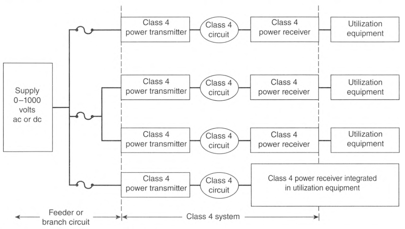
- A short circuit
- A line-to-line fault condition that presents an unacceptable risk of fire or electric shock
- A ground-fault condition that presents an unacceptable risk of fire or electric shock
- An overcurrent condition
- A malfunction of the monitoring or control system that presents an unacceptable risk of fire or electric shock
- Any other condition that presents an unacceptable risk of fire or electric shock
Informational Note: See UL 1400-1, Outline for Fault-Managed Power Systems - Part 1: General Requirements, for information on determining applicable requirements for the listing of Class 4 power systems, including safe operation and limiting the risk of fire and electric shock.
Informational Note Figure 726.121 Class 4 Circuits.
726.122 Class 4 Loads.
Outputs of a Class 4 receiver and power outputs of Class 4 utilization equipment shall be considered a separately derived system if the outputs are used as a supply for a feeder or branch circuit.
Informational Note: Class 4 utilization equipment that does not provide power outputs is not subject to these requirements.
Exception: A Class 4 receiver with limited-power circuit outputs shall be permitted to meet the requirements of Part II of Article 725.
726.124 Class 4 Marking.
(A) Class 4 Transmitter Marking.
The equipment supplying the Class 4 circuits shall be durably marked where plainly visible to indicate each circuit that is a Class 4 circuit. The marking shall also include the maximum voltage and current output for each connection point. Where multiple connection points have the same rating, a single label shall be permitted to be used.
Informational Note: An example of marking is "Class 4: +/- 190V, 5A" for a Class 4 transmitter capable of delivering 1.9 kW from 380 volts line to line.
(B) Class 4 Receiver Marking.
(1) Class 4 Circuits.
A Class 4 receiver or Class 4 utilization equipment shall be durably marked where plainly visible to indicate each circuit that is a Class 4 circuit. The marking shall include the maximum input voltage and current for each connection point.
(2) Output Terminals and Socket Outlets.
Where the Class 4 receiver or Class 4 utilization equipment has outputs, terminals, or socket outlets for providing power to other equipment, each output shall be durably marked where plainly visible. The marking shall include the maximum output voltage and current for each connection point. Where multiple connection points have the same rating, a single label shall be permitted to be used. Class 1, Class 2, and Class 3 circuits shall be identified in accordance with 724.30 or Part II of Article 725.
726.130 Terminals and Connectors.
(A) Listing.
Connecting hardware used on Class 4 distribution systems shall be listed.
(B) Noninterchangeability.
Connectors for Class 4 circuits shall be designed such that they are not interchangeable with non—power-limited sources located on the same premises.
(C) Guarding.
Any junctions and mating connectors shall be constructed and installed to guard against inadvertent contact with live parts by persons.
726.136 Separation From Electric Light, Power, Class 1, Non-Power-Limited Fire Alarm Circuit, and Medium-Power Network-Powered Broadband Communications Cables.
(A) General.
Cables and conductors of Class 4 circuits shall not be placed in any cable, cable tray, compartment, enclosure, manhole, outlet box, device box, raceway, or similar fitting with conductors of electric light, power, Class 1, non—power-limited fire alarm, and medium-power network-powered broadband communications circuits unless permitted by 726.136(B) through (H).
(B) Separated by Barriers.
Class 4 circuits shall be permitted to be installed together with the conductors of electric light, power, Class 1, non—power-limited fire alarm, and medium-power network-powered broadband communications circuits where they are separated by a barrier.
(C) Raceways Within Enclosures.
In enclosures, Class 4 circuits shall be permitted to be installed in a raceway to separate them from Class 1, non—power-limited fire alarm, and medium-power network-powered broadband communications circuits.
(D) Associated Systems Within Enclosures.
Class 4 circuit conductors in compartments, enclosures, device boxes, outlet boxes, or similar fittings shall be permitted to be installed with electric light, power, Class 1, non—power-limited fire alarm, and medium-power network-powered broadband communications circuits where they are introduced solely to connect the equipment connected to Class 4 circuits, and where either of the following applies:
- The electric light, power, Class 1, non—power-limited fire alarm, and medium-power network-powered broadband communications circuit conductors are routed to maintain a minimum of 6 mm (0.25 in.) separation from the conductors and cables of Class 4 circuits.
- The non-Class 4 circuit conductors operate at 150 volts or less to ground and the Class 4 circuits are installed using Type CL4, Type CL4R, or Type CL4P cables if any CL4 cable conductors extending beyond the jacket are separated by a minimum of 6 mm (0.25 in.) or by a nonconductive sleeve or nonconductive barrier from all other conductors.
(E) Enclosures With Single Openings.
Class 4 circuit conductors entering compartments, enclosures, device boxes, outlet boxes, or similar fittings shall be permitted to be installed with Class 1, non—power-limited fire alarm, and medium-power network-powered broadband communications circuits where they are introduced solely to connect the equipment connected to Class 4 circuits. Where Class 4 circuit conductors must enter an enclosure that is provided with a single opening, they shall be permitted to enter through a single fitting (such as a tee) if the conductors are separated from the conductors of the other circuits by a continuous and firmly fixed nonconductor, such as flexible tubing.
(F) Manholes.
Underground Class 4 circuit conductors in a manhole shall be permitted to be installed with Class 1, non-power-limited fire alarm, and medium-power network-powered broadband communications circuits where one of the following conditions is met:
- The electric light, power, Class 1, non—power-limited fire alarm, and medium-power network-powered broadband communications circuit conductors are in a metal-enclosed cable or Type UF cable.
- The Class 4 circuit conductors are permanently and effectively separated from the conductors of other circuits by a continuous and firmly fixed nonconductor, such as flexible tubing, in addition to the insulation or covering on the wire.
- The Class 4 circuit conductors are permanently and effectively separated from conductors of the other circuits and securely fastened to racks, insulators, or other approved supports.
(G) Cable Trays.
Class 4 circuit conductors shall be permitted to be installed in cable trays where the conductors of the electric light. Class 1, and non—power-limited fire alarm circuits are separated by a solid fixed barrier of a material compatible with the cable tray or where the Class 4 circuits are installed in Type MC cable.
(H) Other Applications.
For other applications, conductors of Class 4 circuits shall be separated by at least 50 mm (2 in.) from conductors of any electric light, power. Class 1, non—power-limited fire alarm, or medium-power network-powered broadband communications circuits unless one of the following conditions is met:
- Either all of the electric light, power, Class 1, non—power-limited fire alarm, and medium-power network-powered broadband communications circuit conductors or all of the Class 4 circuit conductors are in a raceway or in metal-sheathed, metal-clad, non-metallic-sheathed, Type TC, or Type UF cables
- All of the electric light, power, Class 1, non—power-limited fire alarm, and medium-power network-powered broadband communications circuit conductors are permanently separated from all of the Class 4 circuit conductors by a continuous and firmly fixed nonconductor, such as porcelain tubes or flexible tubing, in addition to the insulation on the conductors
726.139 Installation of Conductors of Different Circuits in the Same Cable, Enclosure, Cable Tray, Raceway, or Cable Routing Assembly.
(A) Two or More Class 4 Circuits.
Conductors of two or more Class 4 circuits shall be permitted within the same cable, enclosure, raceway, or cable routing assembly.
(B) Class 4 Circuits With Class 2, Class 3, or Communications Circuits.
Conductors of one or more Class 4 circuits shall be permitted within the same cable assembly as conductors of Class 2, Class 3, or communications circuits if the insulation of the Class 2, Class 3, or communications circuit conductors in the cable is at least that required for Class 4 circuits. Class 4 cables shall be permitted within the same enclosure, raceway, or cable routing assembly as Class 2, Class 3, or communications circuits.
(C) Class 4 Cables With Other Circuit Cables.
Jacketed cables of Class 4 circuits shall be permitted in the same enclosure, cable tray, raceway, or cable routing assembly with jacketed cables of any of the following:
- Power-limited fire alarm systems in compliance with Parts I and III of Article 760
- Nonconductive and conductive optical fiber cables in compliance with Parts I and IV of Article 770
- Communications circuits in compliance with Parts I and IV of Article 805
- Community antenna television and radio distribution systems in compliance with Parts I and IV of Article 820
- Low-power, network-powered broadband communications in compliance with Parts I and IV of Article 830
726.144 Ampacity.
The ampacity of Class 4 cables shall comply with 310.15 based on the temperature rating of the Class 4 cable for conductors sized 16 AWG to 6 AWG. For conductors sized 24 AWG to 17 AWG, the Class 4 cable shall be rated for the intended ampacity as evidenced by the marking FMP-XXA, where XX is the maximum allowable ampacity permitted.
Informational Note No. 1: See 722.179(A) (16) for additional Class 4 cable requirements.
Informational Note No. 2: See UL 1400-1, Outline of Investigation for Fault-Managed Power Systems - Part 1: General Requirements, and UL 1400-2, Outline of Fault-Managed Power Systems - Part 2: Requirements for Class 4 Cables, for information on determining maximum allowable ampacities.
726.170 Listing of Equipment for Class 4 Systems.
The active components of a Class 4 system shall be listed as a Class 4 device. The listing information shall include compatible devices if a listed Class 4 device depends on specific system devices for interoperability, monitoring, or control.
Informational Note No. 1: See UL 1400-1, Outline for Fault-Managed Power Systems - Part I: General Requirements, for information on determining applicable requirements for the listing of Class 4 power systems.
Informational Note No. 2: An example of a dependent active device in a Class 4 system is a transmitter that relies on a particular receiver or receivers as part of the monitoring and control system.
Article 728
Fire-Resistive Cable Systems
728.1 Scope.
This article covers the installation of fire-resistive cables, fire-resistive conductors, and other system components used for survivability of critical circuits to ensure continued operation during a specified time under fire conditions as required in this Code.
728.3 Other Articles.
Wherever the requirements of other articles of this Code and Article 728 differ, the requirements of Article 728 shall apply.
728.4 General.
Fire-resistive cables and conductors and their components shall be tested and listed as a complete system, shall be designated for use in a specific system, and shall not be interchangeable between systems.
Informational Note: One method of defining the fire rating is by testing the system in accordance with UL 2196, Fire Test for Circuit Integrity of Fire-Resistive Power, Instrumentation, Control and Data Cables.
728.5 Installations.
Fire-resistive cable systems installed outside the fire-rated rooms that they serve, such as the electrical room or the fire pump room, shall comply with the requirements of 728.5(A) through (H) and all other installation instructions provided in the listing.
(A) Mounting.
The fire-resistive cable system shall be secured to the building structure in accordance with the listing and the manufacturer's installation instructions.
(B) Supports.
The fire-resistive cable system shall be supported in accordance with the listing and the manufacturer's installation instructions.
Informational Note: The supports are critical for survivability of the system. Each system has its specific support requirements.
(C) Raceways and Couplings.
Where fire-resistive cable is listed to be installed in a raceway, the raceway enclosing the cable, any couplings, and any connectors shall be listed as part of the fire-resistive cable system.
(D) Cable Trays.
Cable trays used as part of a fire-resistive cable system shall be listed as part of the fire-resistive cable system.
(E) Boxes.
Boxes or enclosures used as part of a fire-resistive cable system shall be listed as part of the fire-resistive cable system and shall be secured to the building structure independently of the raceways or cables listed in the system.
(F) Pulling Lubricants.
Fire-resistive cable installed in a raceway shall only use pulling lubricants listed as part of the fire-resistive cable system.
(G) Vertical Supports.
Cables and conductors installed in vertical raceways shall be supported in accordance with the listing of the fire-resistive cable system and in accordance with 300.19.
(H) Splices.
Only splices that are part of the listing for the fire-resistive cable system shall be used. Splices shall have manufacturer's installation instructions.
728.60 Equipment Grounding Conductor.
Fire-resistive cables installed in a raceway requiring an equipment grounding conductor shall use the same fire-resistive cable described in the system unless alternative equipment grounding conductors are listed with the system. Any alternative equipment grounding conductors shall be marked with the system number. The system shall specify a permissible equipment grounding conductor. If not specified, the equipment grounding conductor shall be the same as the fire-resistive cable described in the system.
728.120 Marking.
In addition to the marking required in 310.8, system cables and conductors shall be surface marked with the suffix "FRR" (fire-resistive rating), along with the circuit integrity duration in hours, and with the system identifier.
Article 750
Energy Management Systems
750.1 Scope.
This article applies to the installation and operation of energy management systems.
Informational Note: Performance provisions in other codes establish prescriptive requirements that may further restrict the requirements contained in this article.
750.6 Listing.
Energy management systems shall be one of the following:
- Listed as a complete energy management system
- Listed as a kit for field installation in switch or overcurrent device enclosures
- Listed individual components assembled as a system
750.20 Alternate Power Sources.
An energy management system shall not override any control necessary to ensure continuity of an alternate power source for the following:
750.30 Load Management.
Energy management systems shall be permitted to monitor and control electrical loads and sources in accordance with 750.30(A) through (C).
(A) Load Shedding Controls.
An energy management system shall not override the load shedding controls put in place to ensure the minimum electrical capacity for the following:
(B) Disconnection of Power.
An energy management system shall not cause disconnection of power to the following:
- Elevators, escalators, moving walks, or stairway lift chairs
- Positive mechanical ventilation for hazardous (classified) locations
- Ventilation used to exhaust hazardous gas or reclassify an area
- Circuits supplying emergency lighting
- Essential electrical systems in health care facilities
(C) Capacity of Branch Circuit, Feeder, or Service.
An energy management system shall not cause a branch circuit, feeder, or service to be overloaded. If an EMS is used to limit the current on a conductor, 750.30(C)(1) through (C)(4) shall apply:
(3) Settings.
Adjustable settings shall be permitted if access to the settings is accomplished by at least one of the following:
- Located behind removable and sealable covers over the adjustment means
- Located behind a cover or door that requires the use of a tool to open
- Located behind locked doors accessible only to qualified personnel
- Password protected with password accessible only to qualified personnel
- Software that has password protected access to the adjusting means accessible to qualified personnel only
(4) Marking.
The equipment that supplies the branch circuit, feeder, or service shall be field marked with the following information:
- Maximum current setting
- Date of calculation and setting
- Identification of loads and sources associated with the current limiting feature
- The following or equivalent wording: "The setting for the EMS current limiting feature shall not be bypassed"
750.50 Directory.
Where an energy management system is employed to control electrical power through the use of a remote means, a directory identifying the controlled device(s) and circuit(s) shall be posted on the enclosure of the controller. disconnect, or branch-circuit overcurrent device.
Article 760
Fire Alarm Systems
760.1 Scope.
This article covers the installation of wiring and equipment of fire alarm systems, including all circuits controlled and powered by the fire alarm system.
Informational Note No. 1: Fire alarm systems include fire detection and alarm notification, guard's tour, sprinkler waterflow, and sprinkler supervisory systems. Circuits controlled and powered by the fire alarm system include circuits for the control of building systems safety functions, elevator capture, elevator shutdown, door release, smoke doors and damper control, fire doors and damper control, and fan shutdown, but only where these circuits are powered by and controlled by the fire alarm system.
Informational Note No. 2: See NFPA 72, National Fire Alarm and Signaling Code, for further information on the installation and monitoring for integrity requirements for fire alarm systems.
760.3 Other Articles.
Circuits and equipment shall comply with 760.3(A) through (O). Only those sections of Article 300 referenced in this article shall apply to fire alarm systems.
(B) Ducts, Plenums, and Other Air-Handling Spaces.
Power-limited and non-power-limited fire alarm cables installed in ducts, plenums, or other spaces used for environmental air shall comply with 300.22.
Exception No. 1: Power-limited fire alarm cables selected in accordance with Table 760.154 and installed in accordance with 722.135 and 300.22(B), Exception, shall be permitted to be installed in ducts specifically fabricated for environmental air.
Exception No. 2: Power-limited fire alarm cables selected in accordance with Table 760.154 and installed in accordance with 722.135 shall be permitted to be installed in other spaces used for environmental air (plenums).
(D) Building Control Circuits.
Building control systems (e.g., elevator capture, fan shutdown) associated with the fire alarm system shall comply with Article 725.
(E) Optical Fiber Cables.
Where optical fiber cables are utilized for fire alarm circuits, the cables shall be installed in accordance with Article 770.
(H) Vertical Support for Fire-Resistive Cables and Conductors.
Vertical installations of circuit integrity (CI) cables and conductors installed in a raceway or conductors and cables of fire-resistive cable systems shall be installed in accordance with 300.19.
(K) Cable Routing Assemblies.
Power-limited fire alarm cables shall be permitted to be installed in plenum cable routing assemblies, riser cable routing assemblies, and general-purpose cable routing assemblies selected in accordance with Table 800.154(c), listed in accordance with 800.182, and installed in accordance with 800.110(C) and 800.113.
(L) Communications Raceways.
Power-limited fire alarm cables shall be permitted to be installed in plenum communications raceways, riser communications raceways, and general-purpose communications raceways selected in accordance with Table 800.154(b), listed in accordance with 800.182, and installed in accordance with 800.113 and 362.24 through 362.56, where the requirements applicable to electrical nonmetallic tubing apply.
(M) Temperature Limitations of Power-Limited and Non-Power-Limited Fire Alarm Cables.
The requirements of 310.14(A)(3) on the temperature limitation of conductors shall apply to power-limited fire alarm cables and non—power-limited fire alarms cables.
(N) Identification of Equipment Grounding Conductors.
Equipment grounding conductors shall be identified in accordance with 250.119.
Exception: Conductors with green insulation shall be permitted to be used as ungrounded signal conductors for Types FPLP, FPLR, FPL, and substitute cables installed in accordance with 760.154(A).
(O) Cables for Power-Limited Fire Alarm (PLFA) Circuits.
The listing and installation of cables for power-limited fire alarm circuits shall comply with Part III of this article and Parts I and II of Article 722.
760.21 Access to Electrical Equipment Behind Panels Designed to Allow Access.
Access to electrical equipment shall not be denied by an accumulation of conductors and cables that prevents removal of panels, including suspended ceiling panels.
760.24 Mechanical Execution of Work.
(A) General.
Fire alarm circuits shall be installed in a neat and workmanlike manner. Cables and conductors installed exposed on the surface of ceilings and sidewalls shall be supported by the building structure in such a manner that the cable will not be damaged by normal building use. Such cables shall be supported by hardware, including straps, staples, hangers, listed cable ties identified for securement and support, or similar fittings designed and installed so as not to damage the cable. The installation shall also comply with 300.4 and 300.11.
Informational Note: Paint, plaster, cleaners, abrasives, corrosive residues, or other contaminants might result in an undetermined alteration of PLFA and NPLFA cable properties.
(B) Circuit Integrity (CI) Cable.
Circuit integrity (CI) cables shall be supported at a distance not exceeding 610 mm (24 in.). Where located within 2.1 m (7 ft) of the floor in accordance with 760.53(A)(1) and 760.130(B)(1), as applicable, the cable shall be fastened in an approved manner at intervals of not more than 450 mm (18 in.). Cable supports and fasteners shall be steel.
760.25 Abandoned Cables.
The accessible portion of abandoned fire alarm cables shall be removed. Where cables are identified for future use with a tag, the tag shall be of sufficient durability to withstand the environment involved.
760.30 Fire Alarm Circuit Identification.
Fire alarm circuits shall be identified at terminal and junction locations in a manner that helps to prevent unintentional signals on fire alarm system circuit(s) during testing and servicing of other systems.
760.32 Fire Alarm Circuits Extending Beyond One Building.
Non-power-limited fire alarm circuits and power-limited fire alarm circuits that extend beyond one building and run outdoors shall meet the installation requirements of Parts II, III, and IV of Article 805 and shall meet the installation requirements of Part I of Article 300.
760.33 Supply-Side Overvoltage Protection.
A listed surge-protective device (SPD) shall be installed on the supply side of a fire alarm control panel in accordance with Part II of Article 242.
760.35 Fire Alarm Circuit Requirements.
(A) Non-Power-Limited Fire Alarm (NPLFA) Circuits.
See Parts I and II.
(B) Power-Limited Fire Alarm (PLFA) Circuits.
See Parts I and III.
760.41 NPLFA Circuit Power Source Requirements.
(A) Power Source.
The power source of non—power-limited fire alarm circuits shall comply with Chapters 1 through 4, and the output voltage shall be not more than 600 volts, nominal. The fire alarm circuit disconnect shall be permitted to be secured in the "on" position.
(B) Branch Circuit.
The branch circuit supplying the fire alarm equipment(s) shall supply no other loads. The location of the branch-circuit overcurrent protective device shall be permanently identified at the fire alarm control unit. The circuit disconnecting means shall have red identification, shall be accessible only to qualified personnel, and shall be identified as "FIRE ALARM CIRCUIT." The red identification shall not damage the overcurrent protective devices or obscure the manufacturer's markings. This branch circuit shall not be supplied through ground-fault circuit interrupters or arc-fault circuit-interrupters.
760.43 NPLFA Circuit Overcurrent Protection.
Overcurrent protection for conductors 14 AWG and larger shall be provided in accordance with the conductor ampacity without applying the ampacity adjustment and correction factors of 310.14 to the ampacity calculation. Overcurrent protection shall not exceed 7 amperes for 18 AWG conductors and 10 amperes for 16 AWG conductors.
Exception: Where other articles of this Code permit or require other overcurrent protection.
760.45 NPLFA Circuit Overcurrent Device Location.
Overcurrent devices shall be located at the point where the conductor to be protected receives its supply.
Exception No. 1: Where the overcurrent device protecting the larger conductor also protects the smaller conductor.
Exception No. 2: Transformer secondary conductors. Non-power-limited fire alarm circuit conductors supplied by the secondary of a single-phase transformer that has only a 2-wire (single-voltage) secondary shall be permitted to be protected by overcurrent protection provided by the primary (supply) side of the transformer, provided the protection is in accordance with 450.3 and does not exceed the value determined by multiplying the secondary conductor ampacity by the secondary-to-primary transformer voltage ratio. Transformer secondary conductors other than 2-wire shall not be considered to be protected by the primary overcurrent protection.
Exception No. 3: Electronic power source output conductors. Non—power-limited circuit conductors supplied by the output of a single-phase, listed electronic power source, other than a transformer, having only a 2-wire (single-voltage) output for connection to non—power-limited circuits shall be permitted to be protected by overcurrent protection provided on the input side of the electronic power source, provided this protection does not exceed the value determined by multiplying the non—power-limited circuit conductor ampacity by the output-to-input voltage ratio. Electronic power source outputs, other than 2-wire (single voltage), connected to non—power-limited circuits shall not be considered to be protected by overcurrent protection on the input of the electronic power source.
Informational Note: A single-phase, listed electronic power supply whose output supplies a 2-wire (single-voltage) circuit is an example of a non—power-limited power source that meets the requirements of 760.41.
760.46 NPLFA Circuit Wiring.
760.48 Conductors of Different Circuits in Same Cable, Enclosure, or Raceway.
(A) Class 1 With NPLFA Circuits.
Class 1 and non—power-limited fire alarm circuits shall be permitted to occupy the same cable, enclosure, or raceway without regard to whether the individual circuits are alternating current or direct current, provided all conductors are insulated for the maximum voltage of any conductor in the enclosure or raceway.
(B) Fire Alarm With Power-Supply Circuits.
Power-supply and fire alarm circuit conductors shall be permitted in the same cable, enclosure, or raceway only where connected to the same equipment.
760.49 NPLFA Circuit Conductors.
(A) Sizes and Use.
Only copper conductors shall be permitted to be used for fire alarm systems. Size 18 AWG and 16 AWG conductors shall be permitted to be used, provided they supply loads that do not exceed the ampacities given in Table 402.5 and are installed in a raceway, an approved enclosure, or a listed cable. Conductors larger than 16 AWG shall not supply loads greater than the ampacities given in 310.14, as applicable.
(B) Insulation.
Insulation on conductors shall be rated for the system voltage and not less than 600 volts. Conductors larger than 16 AWG shall comply with Article 310. Conductors 18 AWG and 16 AWG shall be Type KF-2, KFF-2, PAFF, PTFF, PF, PFF, PGF, PGFF, RFH-2, RFHH-2, RFHH-3, SF-2, SFF-2, TF, TFF, TFN, TFFN, ZF, or ZFF. Conductors with other types and thickness of insulation shall be permitted if listed for non—power-limited fire alarm circuit use.
Informational Note: See Table 402.3 for application provisions.
(C) Conductor Materials.
Conductors shall be solid or stranded copper.
Exception to (B) and (C): Wire Types PAF and PTF shall be permitted only for high-temperature applications between 90°C (194°F) and 250°C (482°F).
760.51 Number of Conductors in Cable Trays and Raceways, and Ampacity Adjustment Factors.
(A) NPLFA Circuits and Class 1 Circuits.
Where only non-power-limited fire alarm circuit and Class 1 circuit conductors are in a raceway, the number of conductors shall be determined in accordance with 300.17. The ampacity adjustment factors given in 310.15(C)(1) shall apply if such conductors carry continuous load in excess of 10 percent of the ampacity of each conductor.
(B) Power-Supply Conductors and NPLFA Circuit Conductors.
Where power-supply conductors and non—power-limited fire alarm circuit conductors are permitted in a raceway in accordance with 760.48, the number of conductors shall be determined in accordance with 300.17. The ampacity adjustment factors given in 310.15(C)(1) shall apply as follows:
- To all conductors where the fire alarm circuit conductors carry continuous loads in excess of 10 percent of the ampacity of each conductor and where the total number of conductors is more than three
- To the power-supply conductors only, where the fire alarm circuit conductors do not carry continuous loads in excess of 10 percent of the ampacity of each conductor and where the number of power-supply conductors is more than three
(C) Cable Trays.
Where fire alarm circuit conductors are installed in cable trays, they shall comply with 392.22 and 392.80(A).
760.53 Multiconductor NPLFA Cables.
Multiconductor non-power-limited fire alarm cables that meet the requirements of 760.176 shall be permitted to be used on fire alarm circuits operating at 150 volts or less and shall be installed in accordance with 760.53(A) and (B).
(A) NPLFA Wiring Method.
Multiconductor non-power-limited fire alarm circuit cables shall be installed in accordance with 760.53(A)(1), (A)(2), and (A)(3).
(1) In Raceways, Exposed on Ceilings or Sidewalls, or Fished in Concealed Spaces.
Cable splices or terminations shall be made in listed fittings, boxes, enclosures, fire alarm devices, or utilization equipment. Where installed exposed, cables shall be adequately supported and installed in such a way that maximum protection against physical damage is afforded by building construction such as baseboards, door frames, ledges, and so forth. Where located within 2.1 m (7 ft) of the floor, cables shall be securely fastened in an approved manner at intervals of not more than 450 mm (18 in.).
(2) Passing Through a Floor or Wall.
Cables shall be installed in metal raceway or rigid nonmetallic conduit where passing through a floor or wall to a height of 2.1 m (7 ft) above the floor, unless adequate protection can be afforded by building construction such as detailed in 760.53(A)(1), or unless an equivalent solid guard is provided.
(B) Applications of Listed NPLFA Cables.
The use of non-power-limited fire alarm circuit cables shall comply with 760.53(B)(1) through (B)(4).
(1) Ducts Specifically Fabricated for Environmental Air.
Multiconductor non—power-limited fire alarm circuit cables, Types NPLFP, NPLFR, and NPLF, shall not be installed exposed in ducts specifically fabricated for environmental air.
Informational Note: See 300.22(B).
(2) Other Spaces Used for Environmental Air (Plenums).
(3) Riser.
Cables installed in vertical runs and penetrating one or more floors, or cables installed in vertical runs in a shaft, shall be Type NPLFR. Floor penetrations requiring Type NPLFR shall contain only cables suitable for riser or plenum use.
Exception No. 1: Type NPLF or other cables that are specified in Chapter 3 and are in compliance with 760.49(C) and encased in metal raceway.
Exception No. 2: Type NPLF cables located in a fireproof shaft having firestops at each floor.
Informational Note: See 300.21 for firestop requirements for floor penetrations.
(4) Other Wiring Within Buildings.
Cables installed in building locations other than the locations covered in 760.53(B)(1), (B)(2), and (B)(3) shall be Type NPLF.
Exception No. 2: Type NPLFP or Type NPLFR cables shall be permitted.
760.121 Power Sources for PLFA Circuits.
(A) Power Source.
The power source for a power-limited fire alarm circuit shall be as specified in the following:
Informational Note No. 1: See Chapter 9, Tables 12(A) and 12(B), for the listing requirements for power-limited fire alarm circuit sources.
- A listed PLFA or Class 3 transformer
- A listed PLFA or Class 3 power supply
- Listed equipment marked to identify the PLFA power source
Informational Note No. 2: Examples of listed equipment are a fire alarm control panel with integral power source; a circuit card listed for use as a PLFA source, where used as part of a listed assembly; a current-limiting impedance, listed for the purpose or part of a listed product, used in conjunction with a non—power-limited transformer or a stored energy source, for example, storage battery, to limit the output current.
(B) Branch Circuit.
The branch circuit supplying the fire alarm equipment(s) shall comply with the following requirements:
- The branch circuit shall supply no other loads.
- The branch circuit shall not be supplied through ground-fault circuit interrupters or arc-fault circuit interrupters.
- The location of the branch-circuit overcurrent protective device shall be permanently identified at the fire alarm control unit.
- The circuit disconnecting means shall have red identification, shall be accessible only to qualified personnel, and shall be identified with the following words: "FIRE ALARM CIRCUIT." The red identification shall not damage the overcurrent protective devices or obscure the manufacturer's markings.
- The fire alarm branch-circuit disconnecting means shall be permitted to be secured in the "on" position.
Informational Note: See 210.8(A)(5), Exception, for requirements on receptacles in dwelling-unit unfinished basements that supply power for fire alarm systems.
760.124 Circuit Marking.
The equipment supplying PLFA circuits shall be durably marked where plainly visible to indicate each circuit that is a power-limited fire alarm circuit.
760.127 Wiring Methods on Supply Side of the PLFA Power Source.
Conductors and equipment on the supply side of the power source shall be installed in accordance with the appropriate requirements of Part II and Chapters 1 through 4. Transformers or other devices supplied from power-supply conductors shall be protected by an overcurrent device rated not over 20 amperes.
Exception: The input leads of a transformer or other power source supplying power-limited fire alarm circuits shall be permitted to be smaller than 14 AWG, but not smaller than 18 AWG, if they are not over 300 mm (12 in.) long and if they have insulation that complies with 760.49(B).
760.130 Wiring Methods and Materials on Load Side of the PLFA Power Source.
Fire alarm circuits on the load side of the power source shall be permitted to be installed using wiring methods and materials in accordance with 760.130(A), (B), or a combination of both. Parts I and II of Article 722 shall apply.
(A) NPLFA Wiring Methods and Materials.
NPLFA wiring methods shall be permitted when used in accordance with 760.46, 760.49, or 760.53 for PLFA circuits. Conductors shall be solid or stranded copper. Separation from electric light, power, Class 1, non—power-limited fire alarm circuit conductors, and medium-power network-powered broadband communications cables shall comply with 760.136.
Exception: The ampacity adjustment factors specified in 310.15(C)(1) shall not apply.
(B) PLFA Wiring Methods and Materials.
Power-limited fire alarm conductors and cables described in 722.179 shall be installed as detailed in 722.135 and 760.130(B)(1) through (B)(4). Devices shall be installed in accordance with 110.3(B), 300.1 1(A), and 300.15.
(1) In Raceways, Exposed on Ceilings or Sidewalls, or Fished in Concealed Spaces.
Cable splices or terminations shall be made in listed fittings, boxes, enclosures, fire alarm devices, or utilization equipment. Where installed exposed, cables shall be adequately supported and installed such that maximum protection against physical damage is afforded by building construction such as baseboards, door frames, ledges, and so forth. Where located within 2.1 m (7 ft) of the floor, cables shall be securely fastened in an approved manner at intervals of not more than 450 mm (18 in.).
(2) Passing Through a Floor or Wall.
Cables shall be installed in metal raceways or rigid nonmetallic conduit where passing through a floor or wall to a height of 2.1 m (7 ft) above the floor, unless adequate protection can be afforded by building construction such as detailed in 760.130(B)(1) or unless an equivalent solid guard is provided.
(3) Nonconcealed Spaces.
Cables specified in Chapter 3 and meeting the requirements of 722.179(A)(15)(a) and (A)(15) (b) shall be permitted to be installed in nonconcealed spaces where the exposed length of cable does not exceed 3 m (10 ft).
760.133 Installation of Conductors and Equipment in Cables, Compartments, Cable Trays, Enclosures, Manholes, Outlet Boxes, Device Boxes, Raceways, and Cable Routing Assemblies for Power-Limited Fire Alarm Circuits.
Conductors and equipment for power-limited fire alarm circuits shall be installed in accordance with Parts I and II of Article 722 and 760.136 through 760.143.
760.136 Separation From Electric Light, Power, Class 1, NPLFA, and Medium-Power Network-Powered Broadband Communications Circuit Conductors.
(A) General.
Power-limited fire alarm circuit cables and conductors shall not be placed in any cable, cable tray, compartment, enclosure, manhole, outlet box, device box, raceway, or similar fitting with conductors of electric light, power, Class 1, non—power-limited fire alarm circuits, and medium-power network-powered broadband communications circuits unless permitted by 760.136(B) through (G).
(B) Separated by Barriers.
Power-limited fire alarm circuit cables shall be permitted to be installed together with Class 1, non—power-limited fire alarm, and medium-power network-powered broadband communications circuits where they are separated by a barrier.
(C) Raceways Within Enclosures.
In enclosures, power-limited fire alarm circuits shall be permitted to be installed in a raceway within the enclosure to separate them from Class 1, non—power-limited fire alarm, and medium-power network-powered broadband communications circuits.
(D) Associated Systems Within Enclosures.
Power-limited fire alarm conductors in compartments, enclosures, device boxes, outlet boxes, or similar fittings shall be permitted to be installed with electric light, power, Class 1, non—power-limited fire alarm, and medium-power network-powered broadband communications circuits where they are introduced solely to connect the equipment connected to power-limited fire alarm circuits, and shall comply with either of the following conditions:
- The electric light, power, Class 1, non—power-limited fire alarm, and medium-power network-powered broadband communications circuit conductors are routed to maintain a minimum of 6 mm (1/4 in.) separation from the conductors and cables of power-limited fire alarm circuits.
- The circuit conductors operate at 150 volts or less to ground and also comply with one of the following conditions:
- The fire alarm power-limited circuits are installed using Type FPL. Type FPLR, Type FPLP, or permitted substitute cables if these power-limited cable conductors extending beyond the jacket are separated by a minimum of 6 mm (1/4 in.) or by a nonconductive sleeve or nonconductive barrier from all other conductors.
- The power-limited fire alarm circuit conductors are installed as non—power-limited circuits in accordance with 760.46.
(E) Enclosures With Single Opening.
Power-limited fire alarm circuit conductors entering compartments, enclosures, device boxes, outlet boxes, or similar fittings shall be permitted to be installed with electric light, power, Class 1, non—power-limited fire alarm, and medium-power network-powered broadband communications circuits where they are introduced solely to connect the equipment connected to power-limited fire alarm circuits or to other circuits controlled by the fire alarm system to which the other conductors in the enclosure are connected. Where power-limited fire alarm circuit conductors must enter an enclosure that is provided with a single opening, they shall be permitted to enter through a single fitting (such as a tee), provided the conductors are separated from the conductors of the other circuits by a continuous and firmly fixed nonconductor, such as flexible tubing.
(F) In Hoistways.
In hoistways, power-limited fire alarm circuit conductors shall be installed in rigid metal conduit, rigid nonmetallic conduit, intermediate metal conduit, liquidtight flexible nonmetallic conduit, or electrical metallic tubing. For elevators or similar equipment, these conductors shall be permitted to be installed as provided in 620.21.
(G) Where Protected.
PLFA circuits shall be permitted to be installed together with the conductors of electric light, power, Class 1, non—power-limited fire alarm, and medium-power network-powered broadband communications circuits where they are installed using NPFLA wiring methods and materials in accordance with Part II of Article 760 and are protected by an approved method.
(H) Other Applications.
For other applications, power-limited fire alarm circuit conductors shall be separated by at least 50 mm (2 in.) from conductors of any electric light, power, Class 1, non—power-limited fire alarm, or medium-power network-powered broadband communications circuits unless one of the following conditions is met:
- Either (a) all of the electric light, power, Class 1. non—power-limited fire alarm, and medium-power network-powered broadband communications circuit conductors or (b) all of the power-limited fire alarm circuit conductors are in a raceway or in metal-sheathed, metal-clad, nonmetallic-sheathed, or Type UF cables.
- All of the electric light, power, Class 1, non—power-limited fire alarm, and medium-power network-powered broadband communications circuit conductors are permanently separated from all of the power-limited fire alarm circuit conductors by a continuous and firmly fixed nonconductor, such as porcelain tubes or flexible tubing, in addition to the insulation on the conductors.
760.139 Installation of Conductors of Different PLFA Circuits, Class 2, Class 3, and Communications Circuits in the Same Cable, Enclosure, Cable Tray, Raceway, or Cable Routing Assembly.
(A) Two or More PLFA Circuits.
(Cable and conductors of two or more power-limited fire alarm circuits shall be permitted within the same cable, enclosure, cable tray, raceway, or cable routing assembly.
(B) Class 2 Circuits With PLFA Circuits.
Conductors of one or more Class 2 circuits shall be permitted within the same cable, enclosure, cable tray, raceway, or cable routing assembly with conductors of power-limited fire alarm circuits if the insulation of the Class 2 circuit conductors in the cable, enclosure, raceway, or cable routing assembly is at least that required by the power-limited fire alarm circuits.
(C) Class 3 and Communications Circuits With PLFA Circuits.
Cable and conductors of Class 3 and communications circuits shall be permitted within the same cable, enclosure, cable tray, raceway, or cable routing assembly with cables and conductors of power-limited fire alarm circuits.
(D) Low-Power Network-Powered Broadband Communications Cables and PLFA Cables.
Low-power network-powered broadband communications circuits shall be permitted in the same enclosure, cable tray, raceway, or cable routing assembly with PLFA cables.
(E) Audio System Circuits and PLFA Circuits.
Audio system circuits described in 640.9(C) and installed using Class 2 or Class 3 wiring methods in compliance with 722.135 shall not be installed in the same cable, cable tray, raceway, or cable routing assembly with power-limited conductors or cables.
760.142 Conductor Size.
Conductors of 26 AWG shall be permitted only where spliced with a connector listed as suitable for 26 AWG to 24 AWG or larger conductors that are terminated on equipment or where the 26 AWG conductors are terminated on equipment listed as suitable for 26 AWG conductors. Single conductors shall not be smaller than 18 AWG.
760.143 Support of Conductors.
Power-limited fire alarm circuit conductors shall not be strapped, taped, or attached by any means to the exterior of any conduit or other raceway as a means of support.
760.145 Current-Carrying Continuous Line-Type Fire Detectors.
(A) Application.
Listed continuous line-type fire detectors, including insulated copper tubing of pneumatically operated detectors, employed for both detection and carrying signaling currents shall be permitted to be used in power-limited circuits.
760.154 Applications of Listed PLFA Cables.
PLFA cables shall comply with the requirements described in Table 760.154 or where cable substitutions are made as shown in 760.154(A). Where substitute cables are installed, the wiring requirements of Article 760, Parts 1 and III, shall apply. Types FPLP-CI, FPLR-CI, and FPL-CI cables shall be permitted to be installed to provide 2-hour circuit integrity rated cables.
(A) Fire Alarm Cable Substitutions.
The substitutions for fire alarm cables listed in Table 760.154(A) and illustrated in Figure 760.154(A) shall be permitted. Where substitute cables are installed, the wiring requirements of Article 760, Parts I and III, shall apply. 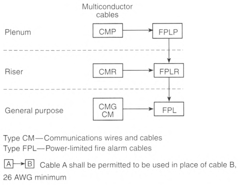
Informational Note: See 800.179 for information on communications cables (CMP, CMR, CMG, CM).
Table 760.154 Applications of Listed PLFA Cables in Buildings.
| Applications | Cable Type | |||
|---|---|---|---|---|
| FPLP & FPLP-CI | FPLR & FPLR-CI | FPL & FPL-CI | ||
| In fabricated ducts as described in 300.22(B) | In fabricated ducts | Y* | N | N |
| In metal raceway that complies with 300.22(B) | Y* | Y* | Y* | |
| In other spaces used for environmental air as described in 300.22(C) | In other spaces used for environmental air | Y* | N | N |
| In metal raceway that complies with 300.22(C) | Y* | Y* | Y* | |
| In plenum communications raceways | Y* | N | N | |
| In plenum cable routing assemblies | Y* | N | N | |
| Supported by open metal cable trays | Y* | N | N | |
| Supported by solid bottom metal cable trays with solid metal covers | Y* | Y* | Y* | |
| In risers | In vertical runs | Y* | Y* | N |
| In metal raceways | Y* | Y* | Y* | |
| In fireproof shafts | Y* | Y* | Y* | |
| In plenum communications raceways | Y* | Y* | N | |
| In plenum cable routing assemblies | Y* | Y* | N | |
| In riser communications raceways | Y* | Y* | N | |
| In riser cable routing assemblies | Y* | Y* | N | |
| In one- and two-family dwellings | Y* | Y* | Y* | |
| Within buildings in other than air-handling spaces and risers | General | Y* | Y* | Y* |
| Supported by cable trays | Y* | Y* | Y* | |
| In any raceway recognized in Chapter 3 | Y* | Y* | Y* | |
| In plenum communications raceway | Y* | Y* | Y* | |
| In plenum cable routing assemblies | Y* | Y* | Y* | |
| In riser communications raceways | Y* | Y* | Y* | |
| In riser cable routing assemblies | Y* | Y* | Y* | |
| In general-purpose communications raceways | Y* | Y* | Y* | |
| In general-purpose cable routing assemblies | Y* | Y* | Y* | |
Note:
"N" indicates that the cable type shall not be permitted to be installed in the application.
Table 760.154(A) Cable Substitutions.
| Cable Type | Permitted Substitutions |
|---|---|
| FPLP | CMP |
| FPLR | CMP, FPLP, CMR |
| FPL | CMP, FPLP, CMR, FPLR, CMG, CM |
760.176 Listing and Marking of NPLFA Cables.
Non-power-limited fire alarm cables installed as wiring within buildings shall be listed in accordance with 760.176(A) and (B), be listed as resistant to the spread of fire in accordance with 760.176(C) through (F), and be marked in accordance with 760.176(G). Cable used in a wet location shall be listed for use in wet locations or have a moisture-impervious metal sheath. Non—power-limited fire alarm cables shall have a temperature rating of not less than 60°C (140°F). Non-power-limited fire alarm cables shall be permitted to contain optical fibers.
Informational Note: See UL 1425, Standard for Cables for Non—Power-Limited Fire-Alarm Circuits, for information on non—power-limited fire alarm cables.
(A) NPLFA Conductor Materials.
Conductors shall be 18 AWG or larger solid or stranded copper.
(B) Insulated Conductors.
Insulation on conductors shall be rated for the system voltage and not less than 600 V. Insulated conductors 14 AWG and larger shall be one of the types listed in Table 310.4(1) or one that is identified for such use. Insulated conductors 18 AWG and 16 AWG shall be in accordance with 760.49.
(C) Type NPLFP.
Type NPLFP non—power-limited fire alarm cable for use in other space used for environmental air shall be listed as being suitable for use in other space used for environmental air as described in 300.22(C) and shall also be listed as having adequate fire-resistant and low smoke-producing characteristics.
Informational Note: See NFPA 262, Standard Method of Test for Flame Travel and Smoke of Wires and Cables for Use in Air-Handling Spaces, for one method of defining a cable that is low-smoke producing and fire-resistant if the cable exhibits a maximum peak optical density of 0.50 or less, an average optical density of 0.15 or less, and a maximum flame spread distance of 1.52 m (5 ft) or less when tested.
(D) Type NPLFR.
Type NPLFR non—power-limited fire alarm riser cable shall be listed as being suitable for use in a vertical run in a shaft or from floor to floor and shall also be listed as having fire-resistant characteristics capable of preventing the carrying of fire from floor to floor.
Informational Note: See UL 1666, Test for Flame Propagation Height of Electrical and Optical-Fiber Cables Installed Vertically in Shafts, for one method of defining fire-resistant characteristics capable of preventing the carrying of fire from floor to floor.
(E) Type NPLF.
Type NPLF non—power-limited fire alarm cable shall be listed as being suitable for general-purpose fire alarm use, with the exception of use in risers, ducts, plenums, and other space used for environmental air, and shall also be listed as being resistant to the spread of fire.
Informational Note: See UL 2556, Wire and Cable Test Methods, for one method of defining resistant to the spread of fire. One method is to demonstrate that the cables do not spread fire to the top of the tray in the "UL Flame Exposure, Vertical Tray Flame Test." The smoke measurements in the test method are not applicable.
Another method of defining resistant to the spread of fire is for the damage (char length) not to exceed 1.5 m (4 ft 11 in.) when performing the FT4 "Vertical Flame Test."
(F) Circuit Integrity (CI) Cable, Fire-Resistive Cable System, or Electrical Circuit Protective System.
Cables that are used for survivability of critical circuits under fire conditions shall be listed and meet the requirements of 760.176(F)(1), (F)(2), or (F)(3).
Informational Note: See NFPA 72, National Fire Alarm and Signaling Code, 12.4.3 and 12.4.4, for additional information on circuit integrity (CI) cable, fire-resistive cable systems, or electrical circuit protective systems used for fire alarm circuits to comply with the survivability requirements to maintain the circuit's electrical function during fire conditions for a defined period of time.
(1) Circuit Integrity (CI) Cables.
Circuit integrity (CI) cables specified in 760.176(C), (D), and (E) and used for survivability of critical circuits shall be marked for an additional classification using the suffix "-CI." In order to maintain its listed fire-resistive rating, CI cables shall only be installed in free air in accordance with 760.24(B). CI cables shall only be permitted to be installed in a raceway where specifically listed and marked as part of an electrical circuit protective fire-resistive cable system as covered in 760.176(F)(2). CI cables shall only be permitted to be installed in a raceway where specifically listed and marked as part of an electrical circuit protective system as covered in 760.176(F)(2).
Informational Note: See UL 2196, Fire Test for Circuit Integrity of Fire-Resistive Power, Instrumentation, Control and Data Cables, and UL 1425, Cables for Non-Power-Limited Fire-Alarm Circuits, for information on establishing a rating for CI cable. The UL Guide Information for Nonpower-limited Fire Alarm Circuits (HNHT) contains information for identifying the cable and its installation limitations to maintain the fire-resistive rating.
(2) Fire-Resistive Cable Systems.
Cables specified in 760.176(C), (D), (E), and (F)(1) that are part of a fire-resistive cable system shall be identified with the system identifier and hourly rating marked on the protectant or the smallest unit container and installed in accordance with the listing of the system.
Informational Note: See UL 2196, Fire Test for Circuit Integrity of Fire-Resistive Power, Instrumentation, Control and Data Cables, for information on establishing a rating for a fire-resistive cable system. The UL Guide Information for Electrical Circuit Integrity Systems (FHIT) contains information for identifying the system and its installation limitations to maintain a minimum fire-resistive rating.
(3) Electrical Circuit Protective System.
Protectants for cables specified in 760.176(C), (D), and (E) that are part of an electrical circuit protective system shall be identified with the protective system identifier and hourly rating marked on the protectant or the smallest unit container and installed in accordance with the listing of the protective system.
Informational Note: See UL 1724, Fire Tests for Electrical Circuit Protective Systems, for information on establishing a rating for an electrical circuit protective system. The UL Guide Information for Electrical Circuit Integrity Systems (FHIT) contains information for identifying the system and its installation limitations to maintain the fire-resistive rating.
(G) NPLFA Cable Markings.
Multiconductor non—power-limited fire alarm cables shall be marked in accordance with Table 760.176(G). Non—power-limited fire alarm circuit cables shall be permitted to be marked with a maximum usage voltage rating of 150 volts. Cables that are listed for circuit integrity shall be identified with the suffix "-CI" as defined in 760.176(F). The temperature rating shall be marked on the jacket of NPLFA cables that have a temperature rating exceeding 60°C (140°F). The jacket of NPLFA cables shall be marked with the conductor size.
Informational Note: Cable types are listed in descending order of fire performance.
Table 760.176(G) NPLFA Cable Markings.
| Cable Marking | Type | Reference |
|---|---|---|
| NPLFP | Non-power-limited fire alarm circuit cable for use in other space used for environmental air | 760.176(C) and (G) |
| NPLFR | Non-power-limited fire alarm circuit riser cable | 760.176(D) and (G) |
| NPLF | Non-power-limited fire alarm circuit cable | 760.176(E) and (G) |
Notes:
- Cables identified in 760.176(C), (D), and (E) and meeting the requirements for circuit integrity shall have the additional classification using the suffix "-CI" (for example, NPLFP-CI, NPLFR-CI, and NPLF-CI).
- Cables containing optical fibers shall be provided with the suffix "-OF".
760.179 Listing and Marking of Insulated Continuous Line-Type Fire Detectors.
Insulated continuous line-type fire detectors shall be listed in accordance with 760.179(A) through (D). Cable used in a wet location shall be listed for use in wet locations or have a moisture-impervious metal sheath.
(A) Listing.
The cable shall be listed as being resistant to the spread of fire in accordance with 722.179(A)(1), (A)(2), and (A)(3).
(C) Markings.
The cable shall be marked as fire resistance Type FPLP, Type FPLR, or Type FPL in accordance with 722.179(B). The voltage rating shall not be marked on the cable. The temperature rating shall be marked on the jacket of cables that have a temperature rating exceeding 60°C (140°F). The jacket of PLFA cables shall be marked with the conductor size.
Informational Note: Voltage ratings on cables might be misinterpreted to suggest that the cables could be suitable for Class 1, electric light, and power applications.
Exception: Voltage markings shall be permitted where the cable has multiple listings and voltage marking is required for one or more of the listings.
Article 770
Optical Fiber Cables
770.1 Scope.
This article covers the installation of optical fiber cables. This article does not cover the construction of optical fiber cables.
770.3 Other Articles.
Installations of optical fiber cables shall comply with 770.3(A) through (D). Only those sections of Chapter 2 and Article 300 referenced in this article shall apply to optical fiber cables.
(C) Hybrid Cables.
Hybrid optical fiber cables shall be classified as electrical cables in accordance with the type of electrical conductors. They shall be constructed, listed, and marked in accordance with the appropriate article for each type of electrical cable.
770.21 Access to Electrical Equipment Behind Panels Designed to Allow Access.
Access to electrical equipment shall not be denied by an accumulation of optical fiber cables that prevents removal of panels, including suspended ceiling panels.
770.24 Mechanical Execution of Work.
(A) General.
Optical fiber cables shall be installed in a neat and workmanlike manner. Cables installed exposed on the surface of ceilings and sidewalls shall be supported by the building structure in such a manner that the cable will not be damaged by normal building use. Such cables shall be secured by hardware, including straps; staples; cable ties listed and identified for securement and support; and hangers, or similar fittings, designed and installed so as not to damage the cable. The installation shall also conform to 300.4 and 300.11. Plenum cable ties and other nonmetallic cable accessories used to secure and support cables in other spaces used for environmental air (plenums) shall be listed as having low smoke and heat release properties in accordance with 800.170.
Informational Note No. 1: See ANSI/NECA/FOA 301-2016, Standard for Installing and Testing Fiber Optic Cables, ANSI/ TIA-568.0-D-2015, Generic Telecommunications Cabling for Customer Premises, and ANSI/TIA 568.3-D-2016, Optical Fiber Cabling and Components Standard, for accepted industry practices.
Informational Note No. 2: See NFPA 90A-2021, Standard for the Installation of Air-Conditioning and Ventilating Systems, for discrete combustible components installed in accordance with 300.22(C).
Informational Note No. 3: Paint, plaster, cleaners, abrasives, corrosive residues, or other contaminants may result in an undetermined alteration of optical fiber cable properties.
770.25 Abandoned Cables.
The accessible portion of abandoned optical fiber cables shall be removed. Where cables are identified for future use with a tag, the tag shall be of sufficient durability to withstand the environment involved.
770.26 Spread of Fire or Products of Combustion.
Installations of optical fiber cables and communications raceways in hollow spaces, vertical shafts, and ventilation or air-handling ducts shall be made so that the possible spread of fire or products of combustion will not be substantially increased. Openings around penetrations of optical fiber cables and communications raceways through fire-resistant-rated walls, partitions, floors, or ceilings shall be fire-stopped using approved methods to maintain the fire resistance rating.
Informational Note: Directories of electrical construction materials published by qualified testing laboratories contain many listing installation restrictions necessary to maintain the fire-resistive rating of assemblies where penetrations or openings are made. Building codes also contain restrictions on membrane penetrations on opposite sides of a fire resistance—rated wall assembly. An example is the 600-mm (24-in.) minimum horizontal separation that usually applies between boxes installed on opposite sides of the wall. Assistance in complying with 770.26 can be found in building codes, fire resistance directories, and product listings.
770.27 Temperature Limitation of Optical Fiber Cables.
Optical fiber cable shall not be used in such a manner that its operating temperature exceeds that of its rating.
770.44 Overhead (Aerial) Optical Fiber Cables.
Overhead optical fiber cables containing a non-current-carrying metallic member entering buildings shall comply with 800.44(A) and (B).
(A) On Poles and In-Span.
Where outside plant optical fiber cables and electric light or power conductors are supported by the same pole or are run parallel to each other in-span, the conditions described in 770.44(A)(1) through (A)(4) shall be met.
(1) Relative Location.
Where practicable, the outside plant optical fiber cables shall be located below the electric light or power conductors.
(2) Attachment to Cross-Arms.
Attachment of outside plant optical fiber cables to a cross-arm that carries electric light or power conductors shall not be permitted.
(4) Clearance.
Supply service drops and sets of overhead service conductors of 0 to 750 volts running above and parallel to optical fiber cable service drops shall have a minimum separation of 300 mm (12 in.) at any point in the span, including the point of their attachment to the building. Clearance of not less than 1.0 m (40 in.) shall be maintained between the two services at the pole.
(B) Above Roofs.
Outside plant optical fiber cables shall have a vertical clearance of not less than 2.5 m (8 ft) from all points of roofs above which they pass.
Exception No. 1: The requirement of 770.44(B) shall not apply to auxiliary buildings such as garages and the like.
Exception No. 2: A reduction in clearance above only the overhanging portion of the roof to not less than 450 mm (18 in.) shall be permitted if (1) not more than 1.2 m (4 ft) of optical fiber cable service drop cable passes above the roof overhang, and (2) the cable is terminated at a through- or above-the-roof raceway or approved support.
Exception No. 3: Where the roof has a slope of not less than 100 mm in 300 mm (4 in. in 12 in.), a reduction in clearance to not less than 900 mm (3 ft) shall be permitted.
Informational Note: See ANSI/IEEE C2-2017, National Electric Safety Code, Part 2, Safety Rules for Overhead Lines, for additional information regarding overhead wires and cables.
770.47 Underground Optical Fiber Cables Entering Buildings.
(A) Underground Systems With Electric Light, Power, Class 1, or Non—Power-Limited Fire Alarm Circuit Conductors.
Underground conductive optical fiber cables entering buildings with electric light, power, Class 1, or non—power-limited fire alarm circuit conductors in a raceway, handhole enclosure, or manhole shall be located in a section separated from such conductors by means of brick, concrete, or tile partitions or by means of a suitable barrier.
(B) Direct-Buried Cables and Raceways.
Direct-buried conductive optical fiber cables shall be separated by at least 300 mm (12 in.) from conductors of any electric light, power, non-power-limited fire alarm circuit conductors, or Class 1 circuit.
Exception No. 1: Separation shall not be required where the electric service conductors are installed in raceways or have metal cable armor.
Exception No. 2: Separation shall not be required where electric light or power branch-circuit or feeder conductors, non—power-limited fire alarm circuit conductors, or Class 1 circuit conductors are installed in a raceway or in metal-sheathed, metal-clad, or Type UF or Type USE cables.
770.48 Unlisted Cables Entering Buildings.
(A) Conductive and Nonconductive Cables.
Unlisted conductive and nonconductive outside plant optical fiber cables shall be permitted to be installed in building spaces, other than risers, ducts used for environmental air, plenums used for environmental air, and other spaces used for environmental air, where the length of the cable within the building, measured from its point of entrance, does not exceed 15 m (50 ft) and the cable enters the building from the outside and is terminated in an enclosure.
The point of entrance shall be permitted to be extended from the penetration of the external wall, roof, or floor slab by continuously enclosing the entrance optical fiber cables in rigid metal conduit (RMC) or intermediate metal conduit (IMC) to the point of emergence.
Informational Note: Splice cases or terminal boxes, both metallic and plastic types, typically are used as enclosures for splicing or terminating optical fiber cables.
(B) Nonconductive Cables in Raceway.
Unlisted nonconductive outside plant optical fiber cables shall be permitted to enter the building from the outside and shall be permitted to be installed in any of the following raceways:
770.49 Metal Entrance Conduit Grounding.
Metal conduit containing optical fiber entrance cable shall be connected by a bonding conductor or grounding electrode conductor to a grounding electrode or, where present, the building grounding electrode system in accordance with 770.100(B).
770.93 Grounding, Bonding, or Interruption of Non-Current-Carrying Metallic Members of Optical Fiber Cables.
Optical fiber cables entering the building or terminating on the outside of the building shall comply with 770.93(A) or (B).
(A) Entering Buildings.
In installations where an optical fiber cable is exposed to contact with electric light or power conductors and the cable enters the building, the non-current-carrying metallic members shall be either grounded or bonded as specified in 770.100 or interrupted by an insulating joint or equivalent device. The grounding or interruption shall be as close as practicable to the point of entrance.
(B) Terminating on the Outside of Buildings.
In installations where an optical fiber cable is exposed to contact with electric light or power conductors and the cable is terminated on the outside of the building, the non-current-carrying metallic members shall be either grounded or bonded as specified in 770.100 or interrupted by an insulating joint or equivalent device. The grounding, bonding, or interruption shall be as close as practicable to the point of termination of the cable.
770.100 Entrance Cable Bonding and Grounding.
If required, the non-current-carrying metallic members of optical fiber cables entering buildings shall be bonded or grounded as specified in 770.100(A) through (D).
(A) Bonding Conductor or Grounding Electrode Conductor.
(1) Insulation.
The bonding conductor or grounding electrode conductor shall be listed and shall be permitted to be insulated, covered, or bare.
(2) Material.
The bonding conductor or grounding electrode conductor shall be copper or other corrosion-resistant conductive material, stranded or solid.
(3) Size.
The bonding conductor or grounding electrode conductor shall not be smaller than 14 AWG. It shall have a current-carrying capacity not less than that of the grounded metallic member(s). The bonding conductor or grounding electrode conductor shall not be required to exceed 6 AWG.
(4) Length.
The bonding conductor or grounding electrode conductor shall be as short as practicable. In one- and two- family dwellings, the bonding conductor or grounding electrode conductor shall be as short as practicable not to exceed 6.0 m (20 ft) in length.
Informational Note: Similar bonding conductor or grounding electrode conductor length limitations applied at apartment buildings and commercial buildings help to reduce voltages that may develop between the building's power and communications systems during lightning events.
Exception: In one- and two-family dwellings if it is not practicable to achieve an overall maximum bonding conductor or grounding electrode conductor length of 6.0 m (20 ft), a separate ground rod meeting the minimum dimensional criteria of 770.100(B)(3)(2) shall be driven, the grounding electrode conductor shall be connected to the separate ground rod in accordance with 770.100(C), and the separate ground rod shall be bonded to the power grounding electrode system in accordance with 770.100(D).
(5) Run in Straight Line.
The bonding conductor or grounding electrode conductor shall be run in as straight a line as practicable.
(6) Physical Protection.
Bonding conductors and grounding electrode conductors shall be protected where exposed to physical damage. Where the bonding conductor or grounding electrode conductor is installed in a metal raceway, both ends of the raceway shall be bonded to the contained conductor or to the same terminal or electrode to which the bonding conductor or grounding electrode conductor is connected.
(B) Electrode.
The bonding conductor and grounding electrode conductor shall be connected in accordance with 770.100(B)(1), (B)(2), or (B)(3).
(1) In Buildings or Structures With an Intersystem Bonding Termination.
If the building or structure served has an intersystem bonding termination as required by 250.94, the bonding conductor shall be connected to the intersystem bonding termination.
Informational Note: See Informational Note Figure 800.100(B)(1) for an illustration of the application of the bonding conductor in buildings or structures equipped with an intersystem bonding termination.
(2) In Buildings or Structures With Grounding Means.
If an intersystem bonding termination is established, 250.94(A) shall apply.
If the building or structure served has no intersystem bonding termination, the bonding conductor or grounding electrode conductor shall be connected to the nearest accessible location on one of the following:
- The building or structure grounding electrode system as covered in 250.50
- The power service accessible means external to enclosures using the options identified in 250.94(A), Exception
- The nonflexible metal power service raceway
- The service equipment enclosure
- The grounding electrode conductor or the grounding electrode conductor metal enclosure of the power service
- The grounding electrode conductor or the grounding electrode of a building or structure disconnecting means that is connected to a grounding electrode as covered in 250.32
- The grounded interior metal water piping system, within 1.5 m (5 ft) from its point of entrance to the building, as covered in 250.52
Informational Note: See Informational Note Figure 800.100(B)(2) for an illustration of the application of the bonding conductor in buildings or structures not equipped with an intersystem bonding termination or terminal block providing access to the building grounding electrode system.
(3) In Buildings or Structures Without Intersystem Bonding Termination or Grounding Means.
If the building or structure served has no intersystem bonding termination or grounding means, as described in 770.100(B)(2), the grounding electrode conductor shall be connected to either of the following:
- To any one of the individual grounding electrodes described in 250.52(A)(1), (A)(2), (A)(3), or (A)(4).
- If the building or structure served has no grounding means, as described in 770.100(B)(2) or (B)(3)(l), to any one of the individual grounding electrodes described in 250.52(A)(7) and (A)(8) or to a ground rod or pipe not less than 1.5 m (5 ft) in length and 12.7 mm (1/2 in.) in diameter, driven, where practicable, into permanently damp earth and separated from lightning protection system conductors as covered in 800.53 and at least 1.8 m (6 ft) from electrodes of other systems. Steam, hot water pipes, or lightning protection system conductors shall not be employed as electrodes for non-current-carrying metallic members.
(D) Bonding of Electrodes.
A bonding jumper not smaller than 6 AWG copper or equivalent shall be connected between the grounding electrode and power grounding electrode system at the building or structure served where separate electrodes are used.
Exception: At mobile homes as covered in 770.106.
Informational Note No. 1: See 250.60 for connection to a lightning protection system.
Informational Note No. 2: Bonding together of all separate electrodes limits potential differences between them and between their associated wiring systems.
770.106 Grounding and Bonding of Entrance Cables at Mobile Homes.
(A) Grounding.
Grounding shall comply with 770.106(A)(1) and (A)(2).
- Installations Without Mobile Home Service Equipment. If there is no mobile home service equipment located within 9.0 m (30 ft) of the exterior wall of the mobile home it serves, the non-current-carrying metallic members of optical fiber cables entering the mobile home shall be grounded in accordance with 770.100(B)(3).
- Installations Without Mobile Home Disconnecting Means. If there is no mobile home disconnecting means grounded in accordance with 250.32 and located within 9.0 m (30 ft) of the exterior wall of the mobile home it serves, the non-current-carrying metallic members of optical fiber cables entering the mobile home shall be grounded in accordance with 770.100(B)(3).
(B) Bonding.
The grounding electrode shall be bonded to the metal frame or available grounding terminal of the mobile home with a copper conductor or other equivalent corrosion-resistant material not smaller than 12 AWG under either of the following conditions:
- If there is no mobile home service equipment or disconnecting means as in 770.106(A)
- If the mobile home is supplied by cord and plug
770.110 Raceways, Cable Routing Assemblies, and Cable Trays for Optical Fiber Cables.
(A) Types of Raceways.
Optical fiber cables shall be permitted to be installed in any raceway that complies with either 770.110(A)(1) or (A)(2).
(2) Communications Raceways.
Optical fiber cables shall be permitted to be installed in listed communications raceways selected in accordance with Table 800.154(b).
(B) Raceway Fill for Optical Fiber Cables.
(2) Nonconductive Optical Fiber Cables With Electric Light or Power Conductors.
Where nonconductive optical fiber cables are installed with electric light or power conductors in a raceway, the raceway fill requirements of Chapters 3 and 9 shall apply.
(C) Cable Routing Assemblies.
Optical fiber cables shall be permitted to be installed in listed cable routing assemblies selected in accordance with Table 800.154(c).
(D) Cable Trays.
Optical fiber cables shall be permitted to be installed in metal or listed nonmetallic cable tray systems.
770.113 Installation of Optical Fiber Cables.
Installation of optical fiber cables shall comply with 770.113(A) through (J). Installation of raceways and cable routing assemblies shall comply with 770.110.
(B) Ducts Specifically Fabricated for Environmental Air.
Installations of optical fiber cables in ducts specifically fabricated for environmental air shall be in accordance with 770.113(B)(1) and (B)(2).
(1) Uses Permitted.
The following cables shall be permitted in ducts specifically fabricated for environmental air as described in 300.22(B) if they are directly associated with the air distribution system:
- Up to 1.22 m (4 ft) of Types OFNP and OFGP
- Types OFNP, OFCP, OFNR, OFCR, OFNG, OFCG, OFN, and OFC installed in raceways that are installed in compliance with 300.22(B)
Informational Note: For information on fire protection of wiring installed in fabricated ducts, see NFPA 90A-2018, Standard for the Installation of Air-Conditioning and Ventilating Systems.
(2) Uses Not Permitted.
Types OFNR, OFCR, OFNG, OFCG, OFN, and OFC shall not be permitted to be installed in ducts specifically fabricated for environmental air as described in 300.22(B).
Informational Note: See NFPA 90A-2021, Standard for the Installation of Air-Conditioning and Ventilating Systems, for information on fire protection of wiring installed in fabricated ducts.
(C) Other Spaces Used for Environmental Air (Plenums).
Installations of optical fiber cables in other spaces used for environmental air shall be in accordance with 770.113(C)(1) and (C)(2).
(1) Uses Permitted.
The following cables shall be permitted in other spaces used for environmental air as described in 300.22(C):
- Types OFNP and OFCP
- Types OFNP and OFCP installed in plenum communications raceways
- Types OFNP and OFCP installed in plenum cable routing assemblies
- Types OFNP and OFCP supported by open metal cable tray systems
- Types OFNP, OFCP, OFNR, OFCR, OFNG, OFCG, OFN, and OFC installed in raceways that are installed in compliance with 300.22(C)
- Types OFNP, OFCP, OFNR, OFCR, OFNG, OFCG, OFN, and OFC supported by solid bottom metal cable trays with solid metal covers in other spaces used for environmental air (plenums), as described in 300.22(C)
- Types OFNP, OFCP, OFNR, OFCR, OFNG, OFCG, OFN, and OFC installed in plenum riser and general-purpose communications raceways supported by solid bottom metal cable trays with solid metal covers in other spaces used for environmental air (plenums), as described in 300.22(C)
(2) Uses Not Permitted.
Types OFNR, OFCR, OFNG, OFCG, OFN, and OFC shall not be permitted to be installed in other spaces used for environmental air (plenums).
Informational Note: See NFPA 90A-2018, Standard for the Installation of Air-Conditioning and Ventilating Systems, for information on fire protection of wiring installed in other spaces used for environmental air.
(D) Risers - Cables in Vertical Runs.
Installations of optical fiber cables in vertical runs shall be in accordance with 770.113(D)(1) and (D)(2).
(l) Uses Permitted. The following cables shall be permitted in vertical runs penetrating one or more floors and in vertical runs in a shaft:.
- Types OFNP, OFCP, OFNR, and OFCR
- Types OFNP, OFCP, OFNR, and OFCR installed in the following:
- Plenum communications raceways
- Plenum cable routing assemblies
- Riser communications raceways
- Riser cable routing assemblies
(2) Uses Not Permitted.
Types OFNG, OFCG, OFN, and OFC shall not be permitted to be installed in vertical runs.
Informational Note: See 770.26 for firestop requirements for floor penetrations.
(E) Risers - Cables Permitted in Metal Raceways.
The following cables and innerducts shall be permitted in metal raceways in a riser having firestops at each floor:
- Types OFNP, OFCP, OFNR, OFCR, OFNG, OFCG, OFN, and OFC
- Types OFNP, OFCP, OFNR, OFCR, OFNG, OFCG, OFN, and OFC installed in the following:
Informational Note: See 770.26 for firestop requirements for floor penetrations.
(F) Risers - Cables Permitted in Fireproof Shafts.
The following cables shall be permitted to be installed in fireproof riser shafts having firestops at each floor:
- Types OFNP, OFCP, OFNR, OFCR, OFNG, OFCG, OFN, and OFC
- Types OFNP, OFCP, OFNR, OFCR, OFNG, OFCG, OFN, and OFC installed in the following:
- Plenum communications raceways
- Plenum cable routing assemblies
- Riser communications raceways
- Riser cable routing assemblies
- General-purpose communications raceways
- General-purpose cable routing assemblies
Informational Note: See 770.26 for firestop requirements for floor penetrations.
(G) Risers - Cables Permitted in One- And Two-Family Dwellings.
The following cables shall be permitted in one- and two- family dwellings:
- Types OFNP, OFCP, OFNR, OFCR, OFNG, OFCG, OFN, and OFC
- Types OFNP, OFCP, OFNR, OFCR, OFNG, OFCG, OFN, and OFC installed in the following:
- Plenum communications raceways
- Plenum cable routing assemblies
- Riser communications raceways
- Riser cable routing assemblies
- General-purpose communications raceways
- General-purpose cable routing assemblies
(H) Cable Trays - Cables Permitted.
(I) Distributing Frames and Cross-Connect Arrays - Cables Permitted.
The following cables shall be permitted to be installed in distributing frames and cross-connect arrays:
(2) Types OFNP, OFCP, OFNR, OFCR, OFNG, OFCG, OFN, and OFC
(3) Types OFNP, OFCP, OFNR, OFCR, OFNG, OFCG, OFN, and OFC installed in the following:
- Plenum communications raceways
- Plenum cable routing assemblies
- Riser communications raceways
- Riser cable routing assemblies
- General-purpose communications raceways
- General-purpose cable routing assemblies
(J) Other Building Locations - Cables Permitted.
The following cables shall be permitted to be installed in building locations other than the locations covered in 770.113(B) through (I):
- Types OFNP, OFCP, OFNR, OFCR, OFNG, OFCG, OFN, and OFC
- Types OFNP, OFCP, OFNR, OFCR, OFNG, OFCG, OFN, and OFC installed in:
- Plenum communications raceways
- Plenum cable routing assemblies
- Riser communications raceways
- Riser cable routing assemblies
- General-purpose communications raceways
- General-purpose cable routing assemblies
- Types OFNP, OFCP, OFNR, OFCR, OFNG, OFCG, OFN, and OFC installed in a raceway of a type recognized in Chapter 3
770.114 Grounding.
Non-current-carrying conductive members of optical fiber cables shall be bonded to a grounded equipment rack or enclosure, or grounded in accordance with the grounding methods specified by 770.100(B) using a conductor specified in 770.100(A).
770.133 Installation of Optical Fibers and Electrical Conductors.
(A) In Cable Trays and Raceways.
Conductive optical fiber cables contained in an armored or metal-clad-type sheath and nonconductive optical fiber cables shall be permitted to occupy the same cable tray or raceway with conductors for electric light, power, Class 1, non-power-limited fire alarm, Type ITC, or medium-power network-powered broadband communications circuits operating at 1000 volts or less. Conductive optical fiber cables without an armored or metal-clad-type sheath shall not be permitted to occupy the same cable tray or raceway with conductors for electric light, power, Class 1, non-power-limited fire alarm, Type ITC, or medium-power network-powered broadband communications circuits, unless all of the conductors of electric light, power, Class 1, non—power-limited fire alarm, and medium-power network-powered broadband communications circuits are separated from all of the optical fiber cables by a permanent barrier or listed divider.
(B) In Cabinets, Outlet Boxes, and Similar Enclosures.
Nonconductive optical fiber cables shall not be permitted to occupy the same cabinet, outlet box, panel, or similar enclosure housing the electrical terminations of an electric light, power, Class 1, non—power-limited fire alarm, or medium-power network-powered broadband communications circuit unless one or more of the following conditions exist:
- The nonconductive optical fiber cables are functionally associated with the electric light, power, Class 1, non-power-limited fire alarm, or medium-power network-powered broadband communications circuit.
- The conductors for electric light, power, Class 1, non-power-limited fire alarm, Type ITC, or medium-power network-powered broadband communications circuits operate at 1000 volts or less.
- The nonconductive optical fiber cables and the electrical terminations of electric light, power, Class 1, non—power-limited fire alarm, or medium-power network-powered broadband communications circuit are installed in factory- or field-assembled control centers.
- The nonconductive optical fiber cables are installed in an industrial establishment where conditions of maintenance and supervision ensure that only qualified persons service the installation.
(C) With Other Circuits. Conductive and nonconductive optical fiber cables shall be permitted in the same raceway, cable tray, box, enclosure, or cable routing assembly, with conductors of any of the following:.
When optical fibers are within the same hybrid cable for electric light, power, Class 1, non—power-limited fire alarm, or medium-power network-powered broadband communications circuits operating at 1000 volts or less, they shall be permitted to be installed only where the functions of the optical fibers and the electrical conductors are associated.
Optical fibers in hybrid optical fiber cables containing only current-carrying conductors for electric light, power, or Class 1 circuits rated 1000 volts or less shall be permitted to occupy the same cabinet, cable tray, outlet box, panel, raceway, or other termination enclosure with conductors for electric light, power, or Class 1 circuits operating at 1000 volts or less.
Optical fibers in hybrid optical fiber cables containing current-carrying conductors for electric light, power, or Class 1 circuits rated over 1000 volts shall be permitted to occupy the same cabinet, cable tray, outlet box, panel, raceway, or other termination enclosure with conductors for electric light, power, or Class 1 circuits in industrial establishments, where conditions of maintenance and supervision ensure that only qualified persons service the installation.
- Class 2 and Class 3 remote-control, signaling, and power-limited circuits in compliance with 645.5(E)(2) or Parts I and II of Article 725
- Power-limited fire alarm systems in compliance with Parts I and III of Article 760
- Communications circuits in compliance with Parts I and V of Article 805
- Community antenna television and radio distribution systems in compliance with Parts I and V of Article 820
- Low-power network-powered broadband communications circuits in compliance with Parts I and V of Article 830
(D) Support of Optical Fiber Cables.
Raceways shall be used for their intended purpose. Optical fiber cables shall not be strapped, taped, or attached by any means to the exterior of any conduit or raceway as a means of support.
Exception: Overhead (aerial) spans of optical fiber cables shall be permitted to be attached to the exterior of a raceway-type mast intended for the attachment and support of such cables.
770.154 Applications of Listed Optical Fiber Cables.
Permitted and nonpermitted applications of listed optical fiber cables shall be as indicated in Table 770.154(a). The permitted applications shall be subject to the installation requirements of 770.110 and 770.113. The substitutions for optical fiber cables in Table 770.154(b) and illustrated in Figure 770.154 shall be permitted.
Table 770.154(a) Applications of Listed Optical Fiber Cables in Buildings.
| Applications | Listed Optical Fiber | |||
|---|---|---|---|---|
| Cable Type | ||||
| OFNP, OFCP | OFNR, OFCR | OFNG, OFCG, OFN, OFC | ||
| In ducts specifically fabricated for environmental air as described in 300.22(B) | In fabricated ducts | Y* | N | N |
| In metal raceway that complies with 300.22(B) | Y* | Y* | Y* | |
| In other spaces used for environmental air (plenums) as described in 300.22(C) | In other spaces used for environmental air | Y* | N | N |
| In metal raceway that complies with 300.22(C) | Y* | Y* | Y* | |
| In plenum communications raceways | Y* | N | N | |
| In plenum cable routing assemblies | Y* | N | N | |
| Supported by open metal cable trays | Y* | N | N | |
| Supported by solid bottom metal cable trays with solid metal covers | Y* | Y* | Y* | |
| In risers | In vertical runs | Y* | Y* | N |
| In metal raceways | Y* | Y* | Y* | |
| In fireproof shafts | Y* | Y* | Y* | |
| In plenum communications raceways | Y* | Y* | N | |
| In plenum cable routing assemblies | Y* | Y* | N | |
| In riser communications raceways | Y* | Y* | N | |
| In riser cable routing assemblies | Y* | Y* | N | |
| In one- and two-family dwellings | Y* | Y* | Y* | |
| Within buildings in other than air-handling spaces and risers | General | Y* | Y* | Y* |
| Supported by cable trays | Y* | Y* | Y* | |
| In distributing frames and cross-connect arrays | Y* | Y* | Y* | |
| In any raceway recognized in Chapter 3 | Y* | Y* | Y* | |
| In plenum communications raceway | Y* | Y* | Y* | |
| In plenum cable routing assemblies | Y* | Y* | Y* | |
| In riser communications raceways | Y* | Y* | Y* | |
| In riser cable routing assemblies | Y* | Y* | Y* | |
| In general-purpose communications raceways | Y* | Y* | Y* | |
| In general-purpose cable routing assemblies | Y* | Y* | Y* | |
Note: "N" indicates that the cable type shall not be permitted to be installed in the application. "Y*" indicates that the cable type shall be permitted to be installed in the application subject to the limitations described in 770.110 and 770.113.
Informational Note No. 1: Part V of Article 770 covers installation methods within buildings. This table covers the applications of listed optical fiber cables in buildings. The definition of Point of Entrance is in 770.2.
Informational Note No. 2: For information on the restrictions to the installation of optical fiber cables in ducts specifically fabricated for environmental air, see 770.113(B).
Table 770.154(b) Cable Substitutions.
| Cable Type | Permitted Substitutions |
|---|---|
| OFNP | None |
| OFCP | OFNP |
| OFNR | OFNP |
| OFCR | OFNP, OFCP, OFNR |
| OFNG, OFN | OFNP, OFNR |
| OFCG, OFC | OFNP, OFCP, OFNR, OFCR, OFNG, OFN |
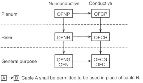
FIGURE 770.154 Cable Substitution Hierarchy.
770.179 Optical Fiber Cables.
Optical fiber cables shall be listed and identified in accordance with 770.179(A) through (G) and shall be marked in accordance with Table 770.179. Optical fiber cables shall have a temperature rating of not less than 60°C (140°F). The temperature rating shall be marked on the jacket of optical fiber cables that have a temperature rating exceeding 60°C (140°F).
Informational Note: See UL 1651-2015, Standard for Optical Fiber Cable, for information on optical fiber cables.
(A) Types OFNP and OFCP.
Types OFNP and OFCP nonconductive and conductive optical fiber plenum cables shall be suitable for use in ducts, plenums, and other space used for environmental air and shall also have adequate fire-resistant and low-smoke-producing characteristics.
Informational Note: See NFPA 262-2019, Standard Method of Test for Flame Travel and Smoke of Wires and Cables for Use in Air-Handling Spaces, for one method of defining that a cable has adequate fire-resistant and low-smoke-producing characteristics where the cable exhibits a maximum peak optical density of 0.50 or less, an average optical density of 0.15 or less, and a maximum flame spread distance of 1.52 m (5 ft) or less.
(B) Types OFNR and OFCR.
Types OFNR and OFCR nonconductive and conductive optical fiber riser cables shall be suitable for use in a vertical run in a shaft or from floor to floor and shall also have the fire-resistant characteristics capable of preventing the carrying of fire from floor to floor.
Informational Note: See ANSI/UL 1666-2017, Standard Test for Flame Propagation Height of Electrical and Optical-Fiber Cable Installed Vertically in Shafts, for one method of defining fire-resistant characteristics capable of preventing the carrying of fire from floor to floor.
(C) Types OFNG and OFCG.
Types OFNG and OFCG nonconductive and conductive general-purpose optical fiber cables shall be suitable for general-purpose use, with the exception of risers and plenums, and shall also be resistant to the spread of fire
Informational Note No. 1: See CSA Vertical Flame Test - Cables in Cable Trays, as described in CSA C22.2 No. 0.3-2009 (R2019), Test Methods for Electrical Wires and Cables, for one method of defining resistant to the spread of fire for the damage (char length) not to exceed 1.5 m (4 ft 11 in.) when performing the test.
Informational Note No. 2: See ANSI/UL 1685-2015, Standard for Safety for Vertical-Tray Fire-Propagation and Smoke-Release Test for Electrical and Optical-Fiber Cables, for another method of defining resistant to the spread of fire where the cables do not spread fire to the top of the tray in the UL flame exposure, vertical tray flame test. The smoke measurements in the test method are not applicable.
(D) Types OFN and OFC.
Types OFN and OFC nonconductive and conductive optical fiber cables shall be suitable for general-purpose use, with the exception of risers, plenums, and other spaces used for environmental air, and shall also be resistant to the spread of fire.
Informational Note No. 1: See ANSI/UL 1685-2015, Standard for Safety for Vertical-Tray Fire-Propagation and Smoke-Release Test for Electrical and Optical-Fiber Cables, for one method of defining resistant to the spread of fire where the cables do not spread fire to the top of the tray in the UL flame exposure, vertical tray flame test. The smoke measurements in the test method are not applicable.
Informational Note No. 2: See CSA Vertical Flame Test - Cables in Cables Trays, as described in CSA C22.2 No. 0.3-2009 (R2019), Test Methods for Electrical Wires and Cables, for another method of defining resistant to the spread of fire where the damage (char length) does not exceed 1.5 m (4 ft 11 in.).
(E) Circuit Integrity (CI), Fire-Resistive Cable System, or Electrical Circuit Protective System.
Cables that are used for survivability of critical circuits under fire conditions shall meet either 770.179(E)(1), (E)(2), or (E)(3).
(1) Circuit Integrity (CI) Cables.
Cables specified in 770.179(A) through (D), and used for survivability of critical circuits, shall be marked with the additional classification using the suffix "CI" In order to maintain its listed fire rating, CI cable shall only be installed in free air in accordance with 770.24. CI cables shall only be permitted to be installed in a raceway where specifically listed and marked as part of a fire-resistive cable system as covered in 770.179(E)(2).
Informational Note: See UL 2196, Standard for Fire Test for Circuit Integrity of Fire-Resistive Power, Instrumentation, Control and Data Cables, for one method of defining CI cable for establishing a minimum 2-hour fire resistance rating for the cable as specified in UL 1651, Optical Fiber Cable. UL Guide Information for Optical Cable Fiber (QAYK) contains information to identify the cable and its installation limitations to maintain the fire-resistive rating.
(2) Fire-Resistive Cables.
Cables specified in 770.179(A) through (D) and 770.179(E)(1) that are part of an electrical circuit protective system shall be fire-resistive cable and identified with the protective system number on the product or on the smallest unit container in which the product is packaged and installed in accordance with the listing of the protective system.
Informational Note: See UL 2196, Standard for Fire Test for Circuit Integrity of Fire-Resistive Power, Instrumentation, Control and Data Cables, for one method of defining an electrical circuit protective system for establishing a rating for the system. UL Guide Information for Electrical Circuit Integrity Systems (FHIT) contains information to identify the system and its installation limitations to maintain a minimum fire-resistive rating.
(F) Field-Assembled Optical Fiber Cables.
Field-assembled optical fiber cable shall comply with the following:
- The specific combination of jacket and optical fibers intended to be installed as a field-assembled optical fiber cable shall be one of the types in 770.179(A), (B), or (D) and shall be marked in accordance with Table 770.179.
- The jacket of a field-assembled optical fiber cable shall have a surface marking indicating the specific optical fibers with which it is identified for use.
- The optical fibers shall have a permanent marking, such as a marker tape, indicating the jacket with which they are identified for use.
- The jacket without fibers shall meet the listing requirements for communications raceways in 800.182(A), (B), or (C) in accordance with the cable marking.
(G) Optional Markings.
Cables shall be permitted to be surface marked to indicate special characteristics of the cable materials.
Informational Note: These markings can include, but are not limited to, markings for limited-smoke halogen-free, low-smoke halogen-free, and sunlight resistance.
Table 770.179 Cable Markings.
| Cable Marking | Type |
|---|---|
| OFNP | Nonconductive optical fiber plenum cable |
| OFCP | Conductive optical fiber plenum cable |
| OFNR | Nonconductive optical fiber riser cable |
| OFCR | Conductive optical fiber riser cable |
| OFNG | Nonconductive optical fiber general-purpose cable |
| OFCG | Conductive optical fiber general-purpose cable |
| OFN | Nonconductive optical fiber general-purpose cable |
| OFC | Conductive optical fiber general-purpose cable |
770.180 Grounding Devices.
Where bonding or grounding is required, devices used to connect a shield, a sheath, or noncurrent-carrying metallic members of a cable to a bonding conductor or grounding electrode conductor shall be listed or be part of listed equipment.