Article 500
Hazardous (Classified) Locations, Classes I, II, and III, Divisions 1 and 2
500.1 Scope.
(A) Covered.
This article covers area classification and general requirements for electrical and electronic equipment and wiring rated at all voltages where fire or explosion hazards might exist due to flammable gases, flammable liquid—produced vapors, combustible liquid—produced vapors, combustible dusts, combustible fibers/flyings, or ignitible fibers/flyings in the following:
- Class I, Division 1 or Class I, Division 2 hazardous (classified) locations
- Class II, Division 1 or Class II, Division 2 hazardous (classified) locations
- Class III, Division 1 or Class III, Division 2 hazardous (classified) locations
Informational Note No. 1: See NFPA 497, Recommended Practice for the Classification of Flammable Liquids, Gases, or Vapors and of Hazardous (Classified) Locations for Electrical Installations in Chemical Process Areas, and NFPA 499, Recommended Practice for the Classification of Combustible Dusts and of Hazardous (Classified) Locations for Electrical Installations in Chemical Process Areas, for extracted information referenced in brackets. Only editorial changes were made to the extracted text to make it consistent with this Code.
Informational Note No. 2: See Article 100 for the definition of restricted industrial establishment [as applied to hazardous (classified) locations].
(B) Not Covered.
This article does not cover electrical and electronic equipment and wiring rated at all voltages for the following:
- Zone 0, Zone 1, or Zone 2 hazardous (classified) locations
- Zone 20, Zone 21, or Zone 22 hazardous (classified) locations
- Locations subject to the unique risk and explosion hazards associated with explosives, pyrotechnics, and blasting agents
- Locations where pyrophoric materials are the only materials used or handled
- Features of equipment that involve nonelectrical potential sources of ignition (e.g., couplings, pumps, gearboxes, brakes, hydraulic and pneumatic motors, fans, engines, compressors)
Informational Note No. 1: Common nonelectrical potential sources of ignition include hot surfaces and mechanically generated sparks.
Informational Note No. 2: See ANSI/UL 80079-36, Explosive Atmospheres - Part 36: Non-Electrical Equipment for Explosive Atmospheres - Basic Method and Requirements, and ANSI/UL 80079-37, Explosive Atmospheres - Part 37: Non-Electrical Equipment for Explosive Atmospheres - Non-Electrical Type of Protection Constructional Safety "c" Control of Ignition Source "b", Liquid Immersion "k", for additional information.
500.4 Documentation.
Areas designated as hazardous (classified) locations or determined to be unclassified shall be documented on an area classification drawing and other associated documentation. This documentation shall be available to the authority having jurisdiction (AHJ) and those authorized to design, install, inspect, maintain, or operate electrical equipment at the location.
Informational Note No. 1: See the following standards for additional information on the classification of locations:
- NFPA 30, Flammable and Combustible Liquids Code
- NFPA 32, Standard for Drycleaning Facilities
- NFPA 33, Standard for Spray Application Using Flammable or Combustible Materials
- NFPA 34, Standard for Dipping, Coating, and Printing Processes Using Flammable or Combustible Liquids
- NFPA 35, Standard for the Manufacture of Organic Coatings
- NFPA 36, Standard for Solvent Extraction Plants
- NFPA 45, Standard on Fire Protection for Laboratories Using Chemicals
- NFPA 55, Compressed Gases and Cryogenic Fluids Code
- NFPA 58, Liquefied Petroleum Gas Code
- NFPA 59, Utility LP-Gas Plant Code
- NFPA 497, Recommended Practice for the Classification of Flammable Liquids, Gases, or Vapors and of Hazardous (Classified) Locations for Electrical Installations in Chemical Process Areas
- NFPA 499, Recommended Practice for the Classification of Combustible Dusts and of Hazardous (Classified) Locations for Electrical Installations in Chemical Process Areas
- NFPA 820, Standard for Fire Protection in Wastewater Treatment and Collection Facilities
- ANSI/API RP 500, Recommended Practice for Classification of Locations for Electrical Installations at Petroleum Facilities Classified as Class I, Division 1 and Division 2
- ISA-12.10, Area Classification in Hazardous (Classified) Dust Locations
Informational Note No. 2: See NFPA 77, Recommended Practice on Static Electricity, NFPA 780, Standard for the Installation of Lightning Protection Systems; and API RP 2003, Protection Against Ignitions Arising Out of Static, Lightning, and Stray Currents, for information on protection against static electricity and lightning hazards in hazardous (classified) locations.
Informational Note No. 3: See NFPA 30, Flammable and Combustible Liquids Code; and ANSI/API RP 500, Recommended Practice for Classification of Locations for Electrical Installations at Petroleum Facilities Classified as Class I, Division 1 and Division 2, for information on ventilation.
Informational Note No. 4: See ANSI/API RP 14F, Recommended Practice for Design, Installation, and Maintenance of Electrical Systems for Fixed and Floating Offshore Petroleum Facilities for Unclassified and Class I, Division 1, and Division 2 Locations, for information on electrical systems for hazardous (classified) locations on offshore oil- and gas-producing platforms, drilling rigs, and workover rigs.
Informational Note No. 5: See ANSI/UL 121203, Portable/Personal Electronic Products Suitable for Use in Class I, Division 2, Class I, Zone 2, Class II, Division 2, Class III, Division 1, Class III, Division 2, Zone 21 and Zone 22 Hazardous (Classified) Locations, for information on portable or transportable equipment having self-contained power supplies, such as battery-operated equipment, which could potentially become an ignition source in hazardous (classified) locations.
Informational Note No. 6: See IEC/IEEE 60079-30-2, Explosive atmospheres - Part 30-2: Electrical resistance trace heating - Application guide for design, installation and maintenance, for information on electrical resistance trace heating for hazardous (classified) locations.
Informational Note No. 7: See IEEE 844.2/CSA C293.2, IEEE/CSA Standard for Skin Effect Trace Heating of Pipelines, Vessels, Equipment, and Structures - Application Guide for Design, Installation, Testing, Commissioning, and Maintenance, for information on electric skin effect trace heating for hazardous (classified) locations.
Informational Note No. 8: See IEEE 844.4/CSA C293.4, IEEE/CSA Standard for Impedance Heating of Pipelines and Equipment - Application Guide for Design, Installation, Testing, Commissioning, and Maintenance, for information on electric impedance heating for hazardous (classified) locations.
500.5 Classifications of Locations.
(A) General.
(1) Hazardous (Classified) Locations.
Locations shall be classified depending on the properties of the flammable gas, flammable liquid—produced vapor, combustible liquid—produced vapors, combustible dusts, or fibers/flyings that could be present, and the likelihood that a flammable or combustible concentration or quantity is present. Each room, section, or area shall be considered individually in determining its classification.
Informational Note: Through the exercise of ingenuity in the layout of electrical installations for hazardous (classified) locations, it is frequently possible to locate much of the equipment in a reduced level of classification or in an unclassified location to reduce the amount of special equipment required.
(2) Refrigerant Machinery Rooms Using Ammonia.
Refrigerant machinery rooms that contain ammonia refrigeration systems and are equipped with adequate mechanical ventilation that operates continuously or is initiated by a detection system at a concentration not exceeding 150 ppm shall be permitted to be classified as "unclassified" locations.
Informational Note: See ANSI/IIAR 2, Standard for Design of Safe Closed-Circuit Ammonia Refrigeration Systems, for information on classification and ventilation of areas involving closed-circuit ammonia refrigeration systems.
(B) Class I Locations.
Class I locations are those in which flammable gases, flammable liquid—produced vapors, or combustible liquid—produced vapors are or may be present in the air in quantities sufficient to produce explosive or ignitible mixtures. Class I locations shall include those specified in 500.5(B)(1) and (B)(2).
(1) Class I, Division 1.
A Class I, Division 1 location is a location:
- In which ignitible concentrations of flammable gases, flammable liquid—produced vapors, or combustible liquid—produced vapors can exist under normal operating conditions, or
- In which ignitible concentrations of such flammable gases, flammable liquid—produced vapors, or combustible liquids above their flash points might exist frequently because of repair or maintenance operations or because of leakage, or
- In which breakdown or faulty operation of equipment or processes might release ignitible concentrations of flammable gases, flammable liquid—produced vapors, or combustible liquid—produced vapors and might also cause simultaneous failure of electrical equipment in such a way as to directly cause the electrical equipment to become a source of ignition
Informational Note: This classification usually includes the following locations:
- Where volatile flammable liquids or liquefied flammable gases are transferred from one container to another
- Interiors of spray booths and areas in the vicinity of spraying and painting operations where volatile flammable solvents are used
- Locations containing open tanks or vats of volatile flammable liquids
- Drying rooms or compartments for the evaporation of flammable solvents
- Locations containing fat- and oil-extraction equipment using volatile flammable solvents
- Portions of cleaning and dyeing plants where flammable liquids are used
- Gas generator rooms and other portions of gas manufacturing plants where flammable gas might escape
- Inadequately ventilated pump rooms for flammable gas or for volatile flammable liquids
- Interiors of refrigerators and freezers in which volatile flammable materials are stored in open, lightly stoppered, or easily ruptured containers
- Inside of inadequately vented enclosures containing instruments normally venting flammable gases or vapors to the interior of the enclosure
- Inside of vented tanks containing volatile flammable liquids
- Area between inner and outer roof sections of floating roof tanks containing volatile flammable fluids
- Inadequately ventilated areas within spraying or coating operations using volatile flammable fluids
- Interior of exhaust ducts used to vent ignitible concentrations of gases or vapors
- All other locations where ignitible concentrations of flammable vapors or gases are likely to occur during normal operations
Experience has demonstrated the prudence of avoiding the installation of instrumentation or other electrical equipment in the areas covered in list items (11) through (15). Where it cannot be avoided because it is essential to the process and other locations are not feasible electrical equipment or instrumentation approved for the specific application or consisting of intrinsically safe systems might be considered.
(2) Class I, Division 2.
A Class I, Division 2 location is a location:
- In which volatile flammable gases, flammable liquid-produced vapors, or combustible liquid—produced vapors are handled, processed, or used, but in which the liquids, vapors, or gases will normally be confined within closed containers or closed systems from which they can escape only in case of accidental rupture or breakdown of such containers or systems or in case of abnormal operation of equipment, or
- In which ignitible concentrations of flammable gases, flammable liquid—produced vapors, or combustible liquid—produced vapors are normally prevented by positive mechanical ventilation and which might become hazardous through failure or abnormal operation of the ventilating equipment, or
- That is adjacent to a Class I, Division 1 location, and to which ignitible concentrations of flammable gases, flammable liquid—produced vapors, or combustible liquid-produced vapors above their flash points might occasionally be communicated unless such communication is prevented by adequate positive-pressure ventilation from a source of clean air and effective safeguards against ventilation failure are provided.
Informational Note No. 1: This classification usually includes locations where volatile flammable liquids or flammable gases or vapors are used but that, in the judgment of the authority having jurisdiction, would become hazardous only in case of an accident or of some unusual operating condition. The quantity of flammable material that might escape in case of accident, the adequacy of ventilating equipment, the total area involved, and the record of the industry or business with respect to explosions or fires are all factors that merit consideration in determining the classification and extent of each location.
Informational Note No. 2: See NFPA 30, Flammable and Combustible Liquids Code, and NFPA 58, Liquefied Petroleum Gas Code. Piping without valves, checks, meters, and similar devices would not ordinarily introduce a hazardous condition even if used for flammable liquids or gases. Depending on factors such as the quantity and size of the containers and ventilation, locations used for the storage of flammable liquids or liquefied or compressed gases in sealed containers might be considered either hazardous (classified) or unclassified locations.
(C) Class II Locations.
Class II locations are those that are hazardous because of the presence of combustible dust. Class II locations shall include those specified in 500.5(C)(1) and (C)(2).
(1) Class II, Division 1.
A Class II, Division 1 location is a location:
- In which combustible dust is in the air under normal operating conditions in quantities sufficient to produce explosive or ignitible mixtures, or
- Where mechanical failure or abnormal operation of machinery or equipment might cause such explosive or ignitible mixtures to be produced, and might also provide a source of ignition through simultaneous failure of electrical equipment, through operation of protection devices, or from other causes, or
- In which Group E combustible dusts may be present in quantities sufficient to be hazardous in normal or abnormal operating conditions.
Informational Note: Dusts containing magnesium or aluminum are particularly hazardous, and the use of extreme precaution is necessary to avoid ignition and explosion.
(2) Class II, Division 2.
A Class II, Division 2 location is a location:
- In which combustible dust due to abnormal operations may be present in the air in quantities sufficient to produce explosive or ignitible mixtures; or
- Where combustible dust accumulations are present but are normally insufficient to interfere with the normal operation of electrical equipment or other apparatus, but could as a result of infrequent malfunctioning of handling or processing equipment become suspended in the air; or
- In which combustible dust accumulations on, in, or in the vicinity of the electrical equipment could be sufficient to interfere with the safe dissipation of heat from electrical equipment, or could be ignitible by abnormal operation or failure of electrical equipment.
Informational Note No. 1: The quantity of combustible dust that may be present and the adequacy of dust removal systems are factors that merit consideration in determining the classification and may result in an unclassified area.
Informational Note No. 2: Where products such as seed are handled in a manner that produces low quantities of dust, the amount of dust deposited may not warrant classification.
(D) Class III Locations.
(1) Class III, Division 1.
Class III, Division 1 locations shall include those locations specified in 500.5(D)(1)(a) and (D)(1)(b).
-
Combustible Fibers/Flyings. Locations where nonmetal combustible fibers/flyings are in the air under normal operating conditions in quantities sufficient to produce explosible mixtures or where mechanical failure or abnormal operation of machinery or equipment might cause combustible fibers/flyings to be produced and might also provide a source of ignition through simultaneous failure of electrical equipment, through operation of protection devices, or from other causes shall be classified as Class III, Division 1. Locations where metal combustible fibers/flyings are present shall be classified as Class II, Division 1, Group E.Informational Note No. 1: Such locations usually include some parts of rayon, cotton, and other textile mills; associated manufacturing and processing plants; cotton gins and cottonseed mills; flax-processing plants; clothing manufacturing plants; woodworking plants; and establishments and industries involving similar hazardous processes or conditions.Informational Note No. 2: Combustible fibers/flyings include flat platelet-shaped particulates, such as metal flakes, and fibrous board, such as particle board.
- Ignitible Fibers/Flyings. Locations where ignitible fibers/flyings are handled, manufactured, or used shall be classified as Class III, Division 1.
Informational Note No. 1: Such locations usually include some parts of rayon, cotton, and other textile mills; associated manufacturing and processing plants; cotton gins and cotton-seed mills; flax-processing plants; clothing manufacturing plants; woodworking plants; and establishments and industries involving similar hazardous processes or conditions.
Informational Note No. 2: Ignitible fibers/flyings can include rayon, cotton (including cotton linters and cotton waste), sisal or henequen, istle, jute, hemp, tow, cocoa fiber, oakum, baled waste kapok, Spanish moss, excelsior, and other materials of similar nature.
(2) Class III, Division 2.
Class III, Division 2 locations shall include those locations specified in 500.5(D)(2)(a) and (D)(2)(b).
- Combustible Fibers/Flyings. Locations where nonmetal combustible fibers/flyings might be present in the air in quantities sufficient to produce explosible mixtures due to abnormal operations or where accumulations of nonmetal combustible fibers/flyings accumulations are present but are insufficient to interfere with the normal operation of electrical equipment or other apparatus but could, as a result of infrequent malfunctioning of handling or processing equipment, become suspended in the air shall be classified as Class III, Division 2.
- Ignitible Fibers/Flyings. Locations where ignitible fibers/flyings are stored or handled, other than in the process of manufacture, shall be classified as Class III, Division 2.
500.6 Materials.
(A) Class I Group Classifications.
Class I groups shall be in accordance with 500.6(A)(1) through (A)(4).
Informational Note No. 1: The explosion characteristics of air mixtures of gases or vapors vary with the specific material involved. For Class I locations, Groups A, B, C, and D, the classification involves determinations of maximum explosion pressure and maximum safe clearance between parts of a clamped joint in an enclosure. It is necessary, therefore, that equipment be identified not only for class but also for the specific group of the gas or vapor that will be present.
Informational Note No. 2: Certain chemical atmospheres may have characteristics that require safeguards beyond those required for any of the Class I groups. Carbon disulfide is one of these chemicals because of its low autoignition temperature (90°C) and the small joint clearance permitted to arrest its flame.
(1) Group A.
Acetylene. [497:3.3.5.1.1]
(2) Group B.
Flammable gas, flammable liquid—produced vapor, or combustible liquid—produced vapor mixed with air that may burn or explode, having either a maximum experimental safe gap (MESG) value less than or equal to 0.45 mm or a minimum igniting current ratio (MIC ratio) less than or equal to 0.40. [497:3.3.5.1.2]
Informational Note: A typical Class I, Group B material is hydrogen.
(3) Group C.
Flammable gas, flammable liquid—produced vapor, or combustible liquid—produced vapor mixed with air that may burn or explode, having either a maximum experimental safe gap (MESG) value greater than 0.45 mm and less than or equal to 0.75 mm, or a minimum igniting current (MIC) ratio greater than 0.40 and less than or equal to 0.80. [497:3.3.5.1.3]
Informational Note: A typical Class I, Group C material is ethylene.
(4) Group D.
Flammable gas, flammable liquid—produced vapor, or combustible liquid—produced vapor mixed with air that may burn or explode, having either a maximum experimental safe gap (MESG) value greater than 0.75 mm or a minimum igniting current (MIC) ratio greater than 0.80. [497:3.3.5.1.4]
Informational Note No. 1: A typical Class I, Group D material is propane. [497:3.3.5.1.4].
Informational Note No. 2: See ANSI/ASHRAE 15, Safety Standard for Refrigeration Systems, for information on the classification of areas involving ammonia atmospheres.
(B) Class II Combustible Dust Group Classifications.
(1) Group E.
Atmospheres containing combustible metal dusts, including aluminum, magnesium, and their commercial alloys, or other combustible dusts whose particle size, abrasiveness, and conductivity present similar hazards in the use of electrical equipment. [499:3.3.8.1.1]
Informational Note: Certain metal dusts may have characteristics that require safeguards beyond those required for atmospheres containing the dusts of aluminum, magnesium, and their commercial alloys. For example, zirconium, thorium, and uranium dusts have extremely low ignition temperatures [as low as 20°C (68°F)] and minimum ignition energies lower than any material classified in any of the Class I or Class II groups.
(2) Group F.
Atmospheres containing combustible carbonaceous dusts that have more than 8 percent total entrapped volatiles (see ASTM D3175-2017, Standard Test Method for Volatile Matter in the Analysis Sample of Coal and Coke, for coal and coke dusts) or that have been sensitized by other materials so that they present an explosion hazard. [499:3.3.8.1.2] Coal, carbon black, charcoal, and coke dusts are examples of carbonaceous dusts. [499:A.3.3.8.1.2]
Informational Note: Testing of specific dust samples, following established ASTM testing procedures, is a method used to identify the combustibility of a specific dust and the need to classify those locations containing that material as Group F.
(3) Group G.
Atmospheres containing combustible dusts not included in Group E or Group F, including flour, grain, wood, plastic, and chemicals. [499:3.3.8.1.3]
Informational Note No. 1: See NFPA 499, Recommended Practice for the Classification of Combustible Dusts and of Hazardous (Classified) Locations for Electrical Installations in Chemical Process Areas, for information on group classification of Class II materials.
Informational Note No. 2: The explosion characteristics of air mixtures of dust vary with the materials involved. For Class II locations, Groups E, F, and G, the classification involves the tightness of the joints of assembly and shaft openings to prevent the entrance of dust in the dust-ignitionproof enclosure, the blanketing effect of layers of dust on the equipment that may cause overheating, and the ignition temperature of the dust. It is necessary, therefore, that equipment be identified not only for the class but also for the specific group of dust that will be present.
Informational Note No. 3: See ANSI/IEEE C2, National Electrical Safety Code, Section 127A, Coal Handling Areas. Certain dusts might require additional precautions due to chemical phenomena that can result in the generation of ignitible gases.
500.7 Protection Techniques.
Electrical and electronic equipment in hazardous (classified) locations shall be protected by one or more of the techniques in 500.7(A) through (P). Suitability of the protection techniques for specific hazardous locations is shown in Chapter 9, Table 13.
(I) Oil Immersion.
This protection technique shall be permitted for current-interrupting contacts in Class I, Division 2 locations as described in 501.115(B)(1)(2).
(K) Detection System for Flammable Gases.
A detection system for flammable gases shall be permitted as a means of protection in restricted industrial establishments.
(1) General.
Any gas detection system used as a protection technique shall meet all of the requirements in 500.7(K)(1)(a) through (K)(1)(e).
- The gas detection equipment used shall be listed for Class I, Division 1 and listed for the detection of the specific gas or vapor to be encountered.
- The gas detection system shall not use portable or transportable equipment or temporary wiring methods.
- The gas detection system shall only use point-type sensors. The system shall be permitted to be augmented with open-path (line-of-sight)-type sensors, but open-path—type sensors shall not be the basis for this protection technique.
- The type of detection equipment and its listing, installation location(s), alarm and shutdown criteria, and calibration frequency shall be documented where gas detectors are used as a protection technique.
- The applications for the use of gas detection systems as a protection technique shall be limited to 500.7(K)(2), (K)(3), or (K)(4).
Informational Note No. 1: See ANSI/UL 121303, Guide for Use of Detectors for Flammable Gases, or ANSI/FM 121303, Guide for Use of Detectors for Flammable Gases, for additional information.
Informational Note No. 2: See ANSI/UL 60079-29-1, Explosive Atmospheres - Part 29-1: Gas Detectors - Performance Requirements of Detectors for Flammable Gases, or ANSI/FM 60079-29-1, Explosive Atmospheres - Part 29-1: Gas Detectors - Performance Requirements of Detectors for Flammable Gases, for additional information.
Informational Note No. 3: See ANSI/API RP 500, Recommended Practice for Classification of Locations for Electrical Installations at Petroleum Facilities Classified as Class I, Division 1 and Division 2, for additional information.
Informational Note No. 4: See ANSI/UL 60079-29-2, Explosive Atmospheres - Part 29-2: Gas Detectors - Selection, Installation, Use and Maintenance of Detectors for Flammable Gases and Oxygen, or ANSI/FM-60079-29-2, Explosive atmospheres - Part 29-2: Gas Detectors - Selection, Installation, Use and Maintenance of Detectors for Flammable Gases and Oxygen, for additional information.
(2) Inadequate Ventilation.
A location, enclosed space, or building that is classified as a Class I, Division 1 location due to inadequate ventilation and is provided with a detection system for flammable gases shall be permitted to use electrical equipment, installation methods, and wiring practices suitable for Class I, Division 2 installations. Sensing a gas concentration of not more than 40 percent of the lower flammable limit or a gas detector system malfunction shall activate an alarm (audible or visual, or both, as most appropriate for the area).
(3) Interior of a Building or Enclosed Space.
Any building or enclosed space that does not contain a source of flammable gases or vapors that is located in, or has an opening into, a Class I, Division 2 hazardous (classified) location and is provided with a detection system for flammable gases shall be permitted to use electrical equipment, installation methods, and wiring practices suitable for unclassified installations under all of the following conditions:
- An alarm (audible or visual, or both) shall be sounded at not more than 20 percent of the lower flammable limit.
- Sensing a gas concentration of not more than 40 percent of the lower flammable limit or a gas detector system malfunction shall activate an alarm (audible or visual, or both, as most appropriate for the area) and initiate automatic disconnection of power from all electrical devices in the area that are not suitable for Class I, Division 2.
- The power disconnecting device(s) shall be suitable for Class I, Division 1 if located inside the building or enclosed space. If the disconnecting device(s) is located outside the building or enclosed space, it shall be suitable for the location in which it is installed.
Redundant or duplicate equipment (such as sensors) shall be permitted to be installed to avoid disconnecting electrical power when equipment malfunctions are indicated.
When automatic shutdown could introduce additional or increased hazard, this technique shall not be permitted.
(4) Interior of a Control Panel.
Inside the interior of a control panel containing instrumentation or other equipment using or measuring flammable liquids, gases, or vapors which is provided with a detection system for flammable gases shall be permitted to use electrical equipment, installation methods, and wiring practices suitable for Class I, Division 2 installations.
An alarm (audible or visual, or both) shall be sounded at not more than 40 percent of the lower flammable limit.
(L) Inherently Safe Optical Radiation "op is.".
This protection technique shall be permitted for equipment in Class I or II, Division 1 or 2 locations for which the equipment is identified.
Informational Note: The identified class and division depends on the intended explosive atmosphere and the number of faults applied as part of the protection technique evaluation.
(N) Optical System With Interlock "op sh.".
This protection technique shall be permitted for equipment in Class I or II, Division 1 or 2 locations for which the equipment is identified.
Informational Note: The identified class and division depends on the intended explosive atmosphere and the number of faults applied as part of the protection technique evaluation.
(O) Protection by Skin Effect Trace Heating "IEEE 844.1".
This protection technique shall be permitted for skin effect trace heating equipment in Class I, Division 2; Class II, Division 2; or Class III, Division 2 locations for which it is listed.
(P) Protection by Electrical Resistance Trace Heating "60079-30-1".
This protection technique shall be permitted for electrical resistance trace heating equipment in Class I, Division 1; Class I, Division 2; Class II, Division 1; Class II, Division 2; Class III, Division 1; or Class III, Division 2 locations for which it is listed.
(Q) Protection by Impedance Heating "IEEE 844.3".
This protection technique shall be permitted for impedance heating equipment in Class I, Division 2; Class II, Division 2; or Class III, Division 2 locations for which it is listed.
(U) Special Protection Techniques.
Protection techniques not specified in 500.7(A) through (T) shall be permitted for use in equipment listed for use in hazardous (classified) locations.
Informational Note: See ANSI/UL 60079-33, Explosive Atmospheres - Part 33: Equipment Protection by Special Protection "s", for additional information.
500.8 Equipment.
Explosionproof or dust-ignitionproof equipment shall not be permitted for use at temperatures lower than -25°C (-13°F) unless they are identified for low-temperature service.
Informational Note: At low ambient temperatures, flammable concentrations of vapors might not exist in a location classified as Class I, Division 1 at normal ambient temperature.
(A) Suitability.
Suitability of identified equipment shall be determined by one of the following:
- Equipment listing or labeling
- Evidence of equipment evaluation from a qualified testing laboratory or inspection agency concerned with product evaluation
- Evidence acceptable to the authority having jurisdiction such as a manufacturer's self-evaluation or an owner's engineering judgment
(B) Approval for Class and Properties.
(1) Equipment Identification.
Equipment shall be identified not only for the class of location but also for the explosive, combustible, or ignitible properties of the specific gas, vapor, dust, or fibers/flyings that will be present. In addition, Class I equipment shall not have any exposed surface that operates at a temperature in excess of the autoignition temperature of the specific gas or vapor. Class II equipment shall not have an external temperature higher than that specified in 500.8(D)
Exception No. 1: Group D equipment shall be permitted to be used for atmospheres containing butadiene if all conduit runs into explosion-proof equipment are provided with explosionproof seals installed within 450 mm (18 in.) of the enclosure.
Exception No. 2: Group C equipment shall be permitted to be used for atmospheres containing allyl glycidyl ether, n-butyl glycidyl ether, ethylene oxide, propylene oxide, and acrolein if all conduit runs into explosionproof equipment are provided with explosionproof seals installed within 450 mm (18 in.) of the enclosure.
Informational Note: See 500.8(C)(6)(a) regarding general-purpose equipment. Luminaires and other heat-producing apparatus, switches, circuit breakers, and plugs and receptacles are potential sources of ignition and are investigated for suitability in classified locations. Such types of equipment, as well as cable terminations for entry into explosionproof enclosures, are available as listed for Class I, Division 2 locations. Fixed wiring, however, might use wiring methods that are not evaluated with respect to classified locations. Therefore, wiring products such as cable, raceways, boxes, and fittings are not marked as being suitable for Class I, Division 2 locations.
(2) Equipment Application.
Equipment identified for a Division 1 location shall be permitted in a Division 2 location of the same class, group, and temperature class and shall comply with the requirements of 500.8(B)(2)(a) or (B)(2)(b) as applicable.
- Intrinsically safe apparatus having a control drawing requiring the installation of associated apparatus for a Division 1 installation shall be permitted to be installed in a Division 2 location if the same associated apparatus is used for the Division 2 installation.
- Equipment required to be explosionproof shall incorporate seals in accordance with 501.15(A) or (D) when the wiring methods of 501.10(B) are employed.
(4) Process Seals.
Equipment that depends on a single compression seal, diaphragm, or tube to prevent flammable or combustible fluids from entering the equipment shall be identified for a Class I, Division 2 location even if installed in an unclassified location. Equipment installed in a Class I, Division 1 location shall be identified for the Class I, Division 1 location.
(5) Motors.
Unless otherwise specified, normal operating conditions for motors shall be assumed to be rated full-load steady conditions.
(6) Simultaneous Classifications.
Where flammable gases, flammable liquid—produced vapors, or combustible liquid-produced vapors and combustible dusts are or might be present at the same time, the simultaneous presence of the specific materials shall be considered when determining the safe operating temperature of the electrical equipment.
(C) Marking.
Equipment shall be marked to show the environment for which it has been evaluated. Unless otherwise specified or allowed in 500.8(C)(6), the marking shall include the information specified in 500.8(C)(1) through (C)(5).
(2) Division.
The marking shall specify the division if the equipment is suitable for Division 2 only. Equipment suitable for Division 1 shall be permitted to omit the division marking.
Informational Note: See 500.8(B)(2). Equipment not marked to indicate a division, or marked "Division 1" or "Div. 1," is suitable for both Division 1 and Division 2 locations. Equipment marked "Division 2" or "Div. 2" is suitable for Division 2 locations only.
(3) Material Classification Group.
The marking shall specify the applicable material classification group(s) or specific gas, vapor, dust, or fiber/flying in accordance with 500.6.
Exception: Fixed luminaires marked for use only in Class I, Division 2 or Class II, Division 2 locations shall not be required to indicate the group.
Informational Note: A specific gas, vapor, dust, or fiber/flying is typically identified by the generic name, chemical formula, CAS number, or combination thereof.
(4) Equipment Temperature.
The marking shall specify the temperature class or operating temperature at a 40°C ambient temperature, or at the higher ambient temperature if the equipment is rated and marked for an ambient temperature of greater than 40°C. For equipment installed in a Class II, Division 1 location, the temperature class or operating temperature shall be based on operation of the equipment when blanketed with the maximum amount of dust that can accumulate on the equipment. The temperature class, if provided, shall be indicated using the temperature class (T codes) shown in Table 500.8(C)(4). Equipment for Class I and Class II shall be marked with the maximum safe operating temperature, as determined by simultaneous exposure to the combinations of Class I and Class II conditions.
Exception: Equipment of the non-heat-producing type, such as junction boxes, conduit, and fittings, and equipment of the heat-producing type having a maximum temperature not more than 100°C shall not be required to have a marked operating temperature or temperature class.
Informational Note: More than one marked temperature class or operating temperature, for gases and vapors, dusts, and different ambient temperatures, may appear.
Table 500.8(C)(4) Classification of Maximum Surface Temperature.
| Maximum Temperature | Temperature Class (T Code) |
|
|---|---|---|
| °C | °F | |
| 450 | 842 | T1 |
| 300 | 572 | T2 |
| 280 | 536 | T2A |
| 260 | 500 | T2B |
| 230 | 446 | T2C |
| 215 | 419 | T2D |
| 200 | 392 | T3 |
| 180 | 356 | T3A |
| 165 | 329 | T3B |
| 160 | 320 | T3C |
| 135 | 275 | T4 |
| 120 | 248 | T4A |
| 100 | 212 | T5 |
| 85 | 185 | T6 |
(5) Ambient Temperature Range.
Electrical equipment designed for use in the ambient temperature range between —25°C to +40°C shall require no ambient temperature marking. For equipment rated for a temperature range other than —25°C to +40°C, the marking shall specify the special range of ambient temperatures in degrees Celsius. The marking shall include either the symbol "Ta" or "Tamb."
Informational Note: As an example, such a marking might be "—30°C ≤ Ta ≤ +40°C."
(6) Special Allowances.
- General-Purpose Equipment. Fixed general-purpose equipment in Class I locations, other than fixed luminaires, that is acceptable for use in Class I, Division 2 locations shall not be required to be marked with the class, division, group, temperature class, or ambient temperature range.
- Dusttight Equipment, Fixed dusttight equipment, other than fixed luminaires, that is acceptable for use in Class II, Division 2 and Class III locations shall not be required to be marked with the class, division, group, temperature class, or ambient temperature range.
- Associated Apparatus. Associated intrinsically safe apparatus and associated nonincendive field wiring apparatus that are not protected by an alternative type of protection shall not be marked with the class, division, group, or temperature class. Associated intrinsically safe apparatus and associated nonincendive field wiring apparatus shall be marked with the class, division, and group of the apparatus to which it is to be connected.
- Simple Apparatus. "Simple apparatus" as defined in Article 100 Part III, shall not be required to be marked with class, division, group, temperature class, or ambient temperature range.
(D) Temperature.
(1) Class I Temperature.
The temperature marking specified in 500.8(C) shall not exceed the autoignition temperature of the specific gas or vapor to be encountered.
Informational Note: See NFPA 497, Recommended Practice for the Classification of Flammable Liquids, Gases, or Vapors and of Hazardous (Classified) Locations for Electrical Installations in Chemical Process Areas, for information on autoignition temperatures of gases and vapors.
(2) Class II Temperature.
The temperature marking specified in 500.8(C) shall be less than the ignition temperature of the specific dust or metal fiber/flying to be encountered. For organic dusts that might dehydrate or carbonize, the temperature marking shall not exceed the lower of either the ignition temperature or 165°C (329°F).
Informational Note: See NFPA 499, Recommended Practice for the Classification of Combustible Dusts and of Hazardous (Classified) Locations for Electrical Installations in Chemical Process Areas, for minimum ignition temperatures of specific dusts.
(3) Class III Temperature.
The temperature marking specified in 500.8(C) shall be less than the ignition temperature of the specific fiber/flying to be encountered, except as specified in 500.8(D)(3)(a) or (D)(3)(b).
- For nonmetal combustible fibers/flyings that might dehydrate or carbonize, the temperature marking shall not exceed the lower of either the ignition temperature or 165°C (329°F).
- When ignitible fibers/flyings are present, the maximum surface temperatures under operating conditions shall not exceed 165°C (329°F) for equipment that is not subject to overloading, and 120°C (248°F) for equipment (such as motors or power transformers) that might be overloaded.
(E) Threading.
The supply connection entry thread form shall be NPT or metric. Conduit and fittings shall be made wrench-tight to prevent sparking when fault current flows through the conduit system, and to ensure the explosionproof integrity of the conduit system where applicable. Equipment provided with threaded entries for field wiring connections shall be installed in accordance with 500.8(E)(1) or (E)(2) and with (E)(3).
(1) Equipment Provided With Threaded Entries for NPT-Threaded Conduit or Fittings.
For equipment provided with threaded entries for NPT-threaded conduit or fittings, listed conduit, listed conduit fittings, or listed cable fittings shall be used. All NPT-threaded conduit and fittings shall be threaded with a National (American) Standard Pipe Taper (NPT) thread.
NPT-threaded entries into explosionproof equipment shall be made up with at least five threads fully engaged.
Exception: For listed explosionproof equipment, joints with factory-threaded NPT entries shall be made up with at least four and one-half threads fully engaged.
Informational Note No. 1: See ASME B1.20.1, Pipe Threads, General Purpose (Inch), for thread specifications for male NPT threads.
Informational Note No. 2: See ASME B1.20.1, Pipe Threads, General Purpose (Inch), and ANSI/UL 1203, Explosion-Proof and Dust-Ignition-Proof Electrical Equipment for Use in Hazardous (Classified) Locations, for information on female NPT-threaded entries using modified National Standard Pipe Taper (NPT) threads.
(2) Equipment Provided With Threaded Entries for Metric-Threaded Fittings.
For equipment with metric-threaded entries, listed conduit fittings or listed cable fittings shall be used. Such entries shall be identified as being metric, or listed adapters to permit connection to conduit or NPT-threaded fittings shall be provided with the equipment and shall be used for connection to conduit or NPT-threaded fittings.
Metric-threaded fittings installed into explosionproof equipment shall have a class of fit of at least 6g/6H and shall be made up with at least five threads fully engaged.
Informational Note: See ISO 965-1, ISO general purpose metric screw threads - Tolerances - Part 1: Principles and basic data, and ISO 965-3, ISO general purpose metric screw threads - Tolerances - Part 3: Deviations for constructional screw threads, for threading specifications for metric-threaded entries.
(3) Unused Openings.
All unused openings shall be closed with blanking elements or close-up plugs that are listed for the location. The thread engagement shall comply with the requirements of 500.8(E)(1) or (E)(2).
(G) Equipment Involving Optical Radiation.
The risk of ignition from optical radiation shall be evaluated for laser equipment, optical fiber equipment, and any other convergent light sources or beams where light is focused in one single point within a hazardous area with a wavelength range of 380 nm to 10 pm. This requirement shall include optical equipment that is located outside the explosive atmosphere, but whose emitted optical radiation enters such atmospheres.
Informational Note: See ANSI/UL 60079-28, Explosive Atmospheres - Part 28: Protection of Equipment and Transmission Systems Using Optical Radiation, for information on types of protection that can be applied to minimize the risk of ignition in explosive atmospheres from optical radiation.
Article 501
Class I Locations
501.1 Scope.
This article covers the requirements for electrical and electronic equipment and wiring for all voltages in Class I, Division 1 and Division 2 locations where flammable gases, flammable liquid—produced vapors, or combustible liquid—produced vapors are or might be present in the air in quantities sufficient to produce explosive or ignitible mixtures.
501.5 Zone Equipment.
Equipment listed and marked in accordance with 505.9(C)(2) for use in Zone 0, 1, or 2 locations shall be permitted in Class I, Division 2 locations for the same gas and with a suitable temperature class. Equipment listed and marked in accordance with 505.9(C)(2) for use in Zone 0 locations shall be permitted in Class I, Division 1 or Division 2 locations for the same gas and with a suitable temperature class.
501.10 Wiring Methods.
(A) Class I, Division 1.
(1) General.
In Class I, Division 1 locations, the following wiring methods shall be permitted:
Informational Note No. 1: See Article 100 for the definition of restricted industrial establishment [as applied to hazardous (classified) locations].
- Threaded rigid metal conduit (RMC) or threaded intermediate metal conduit (IMC), including RMC or IMC conduit systems with supplemental corrosion protection coatings.
- PVC conduit, RTRC conduit, or HDPE conduit, where encased in a concrete envelope a minimum of 50 mm (2 in.) thick and provided with not less than 600 mm (24 in.) of cover measured from the top of the conduit to grade. The concrete encasement shall be permitted to be omitted where it is in accordance with 514.8(C) or 515.8(A). RMC or IMC conduit shall be used for the last 600 mm (24 in.) of the underground run to emergence or to the point of connection to the aboveground raceway. An equipment grounding conductor shall be included to provide for electrical continuity of the raceway system and for grounding of non—current-carrying metal parts.
- Type MI cable terminated with fittings listed for the location. Type MI cable shall be installed and supported to avoid tensile stress at the termination fittings.
- In restricted industrial establishments, Type MC-HL cable listed for use in Class I, Zone 1 or Division 1 locations, with a gas/vaportight continuous corrugated metallic sheath, an overall jacket of suitable polymeric material, and a separate equipment grounding conductor(s) in accordance with 250.122, and terminated with fittings listed for the application. If installed in a ladder, ventilated trough, or ventilated channel cable tray, the cable shall be installed in accordance with 392.22. Type MC-HL cable shall be installed in accordance with Part II of Article 330.
- In restricted industrial establishments, Type ITC-HL cable listed for use in Class I, Division 1 or Zone 1 locations, with a gas/vaportight continuous corrugated metallic sheath and an overall jacket of suitable polymeric material, terminated with fittings listed for the application, and installed in accordance with 335.4.
- Optical fiber cable Type OFNP, Type OFCP, Type OFNR, Type OFCR, Type OFNG, Type OFCG, Type OFN, or Type OFC installed in raceways in accordance with 501.10(A). These optical fiber cables shall be sealed in accordance with 501.15.
- In restricted industrial establishments for applications limited to 600 volts nominal or less, and where the cable is not subject to physical damage and is terminated with fittings listed for the location, Type TC-ER-HL cable. If installed in a ladder, ventilated trough, or ventilated channel cable tray, the cable shall be installed in accordance with 392.22. Type TC-ER-HL cable shall be listed for use in Class I, Division 1 or Zone 1 locations and shall be installed in accordance with 336.10.
- In restricted industrial establishments, listed Type P cable with metal braid armor and an overall jacket, terminated with fittings listed for the location, and installed in accordance with Part II of Article 337. If installed in a ladder, ventilated trough, or ventilated channel cable tray, the cable shall be installed in accordance with 392.22.
Informational Note No. 3: See UL 1309A, Outline of Investigation for Cable for Use in Mobile Installations, for information on construction, testing, and marking of Type P cable.
(2) Flexible Connections.
If flexibility is necessary to minimize the transmission of vibration from equipment during operation or to allow for movement after installation during maintenance, one of the following shall be permitted:
- Flexible fittings listed for the location.
- Flexible cord in accordance with 501.140, terminated with cord connectors listed for the location.
- In restricted industrial establishments, for applications limited to 600 volts nominal or less where the cable is not subject to physical damage and is terminated with fittings listed for the location, Type TC-ER-HL cable. The cable shall be listed for use in Class I, Division 1 or Zone 1 locations and shall be installed in accordance with 336.10.
- In restricted industrial establishments, listed Type P cable with metal braid armor and an overall jacket where the cable is terminated with fittings listed for the location and installed in accordance with Part II of Article 337.
Informational Note No. 2: See UL 1309A, Outline of Investigation for Cable for Use in Mobile Installations, for information on construction, testing, and marking of Type P cable fittings.
(3) Boxes and Fittings.
All boxes and fittings shall be identified for Class I, Division 1.
Informational Note No. 1: See ANSI/UL 2225, Cables and Cable-Fittings for Use in Hazardous (Classified) Locations, for information on construction, testing, and marking of cables, explosionproof cable fittings, and explosionproof cord connectors for entry into enclosures required to be explosionproof.
Informational Note No. 2: See ANSI/UL 1203, Explosion-Proof and Dust-Ignition-Proof Electrical Equipment for Use in Hazardous (Classified) Locations, for information on construction, testing, and marking of explosionproof conduit fittings for entry into enclosures required to be explosionproof.
(B) Class I, Division 2.
(1) General.
In Class I, Division 2 locations, all wiring methods in accordance with 501.10(A) and the following wiring methods shall be permitted:
Informational Note No. 1: See Article 100 for the definition of restricted industrial establishment [as applied to hazardous (classified) locations].
- Rigid metal conduit (RMC) or intermediate metal conduit (IMC) with listed threaded or threadless fittings, including RMC or IMC conduit systems with supplemental corrosion protection coatings.
- Enclosed gasketed busways and enclosed gasketed wire-ways.
- Type PLTC cable or Type PLTC-ER cable used for Class 2 and Class 3 circuits, including installation in cable tray systems. The cable shall be terminated with listed fittings. Type PLTC-ER cable shall include an equipment grounding conductor in addition to a drain wire that might be present.
- Type ITC cable or Type ITC-ER cable as permitted in 335.4 and terminated with listed fittings. Type ITC-ER cable shall include an equipment grounding conductor in addition to a drain wire.
- Type MC, Type MV, Type TC, or Type TC-ER cable, including installation in cable tray systems. Type TC-ER cable shall include an equipment grounding conductor in addition to a drain wire that might be present. All cable types shall be terminated with listed fittings.
- Where metal conduit will not provide the corrosion resistance needed for the installation environment, any of the following shall be permitted:
- Listed reinforced thermosetting resin conduit (RTRC), factory elbows, and associated fittings, all marked with the suffix -XW
- PVC-coated RMC, factory elbows, and associated fittings
- PVC-coated IMC, factory elbows, and associated fittings
- In restricted industrial establishments, Schedule 80 PVC conduit, factory elbows, and associated fittings
- Optical fiber cable Type OFNP, Type OFCP, Type OFNR, Type OFCR, Type OFNG, Type OFCG, Type OFN, or Type OFC installed in cable trays or any other raceway in accordance with 501.10(B). Optical fiber cables shall be sealed in accordance with 501.15.
- Cablebus.
- In restricted industrial establishments, listed Type P cable with or without metal braid armor, with an overall jacket, and terminated with fittings listed for the location when entering explosionproof, flameproof, or pressurized equipment. The cable shall be installed in accordance with Part II of Article 337.
Informational Note No. 2: See ANSI/UL 1309A, Outline of Investigation for Cable for Use in Mobile Installations, for information on construction, testing, and marking of Type P cable.
(2) Flexible Connections.
If flexibility is necessary to minimize the transmission of vibration from equipment during operation or to allow for movement after installation during maintenance, one or more of the following shall be permitted:
- Listed flexible metal fittings
- Flexible metal conduit with listed fittings and bonded in accordance with 501.30(B)
- Interlocked armor Type MC cable with listed fittings
- Liquidtight flexible metal conduit with listed fittings and bonded in accordance with 501.30(B)
- Liquidtight flexible nonmetallic conduit with listed fittings
- Flexible cord listed for extra-hard usage and terminated with listed fittings, with a conductor for use as an equipment grounding conductor
- For elevator use, an identified elevator cable of Type EO, Type ETP, or Type ETT, shown under the "use" column in Table 400.4 for "hazardous (classified) locations" and terminated with listed fittings
- In restricted industrial establishments, listed Type P cable with or without metal braid armor, with an overall jacket, terminated with listed fittings and installed in accordance with Part II of Article 337
(3) Nonincendive Field Wiring.
Nonincendive field wiring shall be permitted using any of the wiring methods permitted for unclassified locations. Nonincendive field wiring systems shall be installed in accordance with the control drawing(s). Simple apparatus, not shown on the control drawing, shall be permitted in a nonincendive field wiring circuit if the simple apparatus does not interconnect the nonincendive field wiring circuit to any other circuit.
Informational Note: See Article 100 for the definition of simple apparatus.
Separate nonincendive field wiring circuits shall be installed in accordance with one of the following:
- In separate cables
- In multiconductor cables where the conductors of each circuit are within a grounded metal shield
- In multiconductor cables or in raceways, where the conductors of each circuit have insulation with a minimum thickness of 0.25 mm (0.01 in.)
(4) Boxes and Fittings.
Boxes and fittings shall be explosion-proof if required by 501.105(B)(2), 501.115(B)(1), or 501.150(B)(1).
Informational Note No. 1: See ANSI/UL 2225, Cables and Cable-Fittings for Use in Hazardous (Classified) Locations, for information on construction, testing, and marking of cable for entry into enclosures required to be explosionproof.
Informational Note No. 2: See ANSI/UL 1203, Explosion-Proof and Dust-Ignition-Proof Electrical Equipment for Use in Hazardous (Classified) Locations, for information on construction, testing, and marking of explosionproof conduit fittings for entry into enclosures required to be explosionproof.
501.15 Sealing and Drainage.
Seals in conduit and cable systems shall comply with 501.15(A) through (F). Sealing compound shall be used in Type MI cable termination fittings to exclude moisture and other fluids from the cable insulation.
Informational Note No. 1: Seals are provided in conduit and cable systems to minimize the passage of gases and vapors and prevent the passage of flames from one portion of the electrical installation to another through the conduit. Such communication through Type MI cable is inherently prevented by construction of the cable. Unless specifically designed and tested for the purpose, conduit and cable seals are not intended to prevent the passage of liquids, gases, or vapors at a continuous pressure differential across the seal. Even at differences in pressure across the seal equivalent to a few inches of water, there may be a slow passage of gas or vapor through a seal and through conductors passing through the seal. Temperature extremes and highly corrosive liquids and vapors can affect the ability of seals to perform their intended function.
Informational Note No. 2: Gas or vapor leakage and propagation of flames may occur through the interstices between the strands of standard stranded conductors larger than 2 AWG. Special conductor constructions, such as compacted strands or sealing of the individual strands, are means of reducing leakage and preventing the propagation of flames.
(A) Conduit Seals, Class I, Division 1.
In Class I, Division 1 locations, conduit seals shall be located in accordance with 501.15(A)(1) through (A)(4).
(1) Entering Enclosures.
Each conduit entry into an explosionproof enclosure shall have a conduit seal where either of the following conditions apply:
- The enclosure contains apparatus, such as switches, circuit breakers, fuses, relays, or resistors that may produce arcs, sparks, or temperatures that exceed 80 percent of the autoignition temperature, in degrees Celsius, of the gas or vapor involved in normal operation.Exception: Seals shall not be required for conduit entering an enclosure under any one of the following conditions:
- The switch, circuit breaker, fuse, relay, or resistor is enclosed within a chamber hermetically sealed against the entrance of gases or vapors.
- The switch, circuit breaker, fuse, relay, or resistor is immersed in oil in accordance with 501.115(B)(1)(2).
- The switch, circuit breaker, fuse, relay, or resistor is enclosed within an enclosure, identified for the location, and marked "Leads Factory Sealed," or "Factory Sealed," "Seal not Required," or equivalent.
- The switch, circuit breaker, fuse, relay, or resistor is part of a nonincendive circuit.
- The entry is metric designator 53 (trade size 2) or larger, and the enclosure contains terminals, splices, or taps.
An enclosure, identified for the location, and marked "Leads Factory Sealed", or "Factory Sealed," or "Seal not Required," or equivalent shall not be considered to serve as a seal for another adjacent enclosure that is required to have a conduit seal.
Conduit seals shall be installed within 450 mm (18 in.) from the enclosure or as required by the enclosure marking. Only threaded couplings, or explosionproof fittings such as unions, reducers, elbows, and capped elbows that are not larger than the trade size of the conduit, shall be permitted between the sealing fitting and the explosionproof enclosure.
(2) Pressurized Enclosures.
Conduit seals shall be installed within 450 mm (18 in.) of the enclosure in each conduit entry into a pressurized enclosure where the conduit is not pressurized as part of the protection system.
Informational Note No. 1: Installing the seal as close as possible to the enclosure will reduce problems with purging the dead airspace in the pressurized conduit.
Informational Note No. 2: See NFPA 496, Standard for Purged and Pressurized Enclosures for Electrical Equipment, for information regarding pressurized enclosures.
(3) Two or More Explosionproof Enclosures.
Where two or more explosionproof enclosures that require conduit seals are connected by nipples or runs of conduit not more than 900 mm (36 in.) long, a single conduit seal in each such nipple connection or run of conduit shall be considered sufficient if the seal is located not more than 450 mm (18 in.) from either enclosure.
(4) Class I, Division 1 Boundary.
A conduit seal shall be required in each conduit run leaving a Division 1 location. The sealing fitting shall be permitted to be installed on either side of the boundary within 3.05 m (10 ft) of the boundary, and it shall be designed and installed to minimize the amount of gas or vapor within the portion of the conduit installed in the Division 1 location that can be communicated beyond the seal. The conduit run between the conduit seal and the point at which the conduit leaves the Division 1 location shall contain no union, coupling, box, or other fitting except for a listed explosionproof reducer installed at the conduit seal.
Where the seal is located on the Division 2 side of the boundary, the Division 1 wiring method shall extend into the Division 2 area to the seal.
Exception No. 1: Metal conduit that contains no unions, couplings, boxes, or fittings, that passes completely through a Division 1 location with no fittings installed within 300 mm (12 in.) of either side of the boundary, shall not require a conduit seal if the termination points of the unbroken conduit are located in unclassified locations.
Exception No. 2: For underground conduit installed in accordance with 300.5 where the boundary is below grade, the sealing fitting shall be permitted to be installed after the conduit emerges from below grade, but there shall be no union, coupling, box, or fitting, other than listed explosionproof reducers at the sealing fitting, in the conduit between the sealing fitting and the point at which the conduit emerges from below grade.
(B) Conduit Seals, Class I, Division 2.
In Class I, Division 2 locations, conduit seals shall be located in accordance with 501.15(B)(1) and (B)(2).
(1) Entering Enclosures.
For connections to enclosures that are required to be explosionproof, a conduit seal shall be provided in accordance with 501.15(A)(1)(1) and (A)(3). All portions of the conduit run or nipple between the seal and enclosure shall comply with 501.10(A).
(2) Class I, Division 2 Boundary.
A conduit seal shall be required in each conduit run leaving a Class I. Division 2 location. The sealing fitting shall be permitted to be installed on either side of the boundary within 3.05 m (10 ft) of the boundary and it shall be designed and installed to minimize the amount of gas or vapor within the portion of the conduit installed in the Division 2 location that can be communicated beyond the seal. Wiring methods permitted in 501.10(B)(1)(1) or (B)(1)(6) shall be used between the sealing fitting and the point at which the conduit leaves the Division 2 location, and a threaded connection shall be used at the sealing fitting. The conduit run between the conduit seal and the point at which the conduit leaves the Division 2 location shall contain no union, coupling, box, or other fitting except for a listed explosionproof reducer installed at the conduit seal. Such seals shall not be required to be explosionproof but shall be identified for the purpose of minimizing the passage of gases permitted under normal operating conditions and shall be accessible.
Informational Note No. 1: See ANSI/UL 514B, Conduit, Tubing, and Cable Fittings, for additional information.
Exception No. 1: Metal conduit that contains no unions, couplings, boxes, or fittings and that passes completely through a Division 2 location with no fittings installed within 300 mm (12 in.) of either side of the boundary shall not require a seal if the termination points of the unbroken conduit are located in unclassified locations.
Exception No. 2: Conduit terminating in an unclassified location where the metal conduit transitions to cable tray, cablebus, ventilated busway, or Type MI cable, or to cable not installed in any cable tray or raceway system, shall not require a seal where passing from the Division 2 location into the unclassified location under the following conditions:
(1) The unclassified location is outdoors, or the unclassified location is indoors and the conduit system is entirely in one room.
(2) The conduits do not terminate at an enclosure containing an ignition source in normal operation.
Exception No. 3: Conduit passing from an enclosure or a room permitted to use general-purpose equipment as a result of pressurization into a Division 2 location shall not require a seal at the boundary.
Informational Note No. 2: See NFPA 496, Standard for Purged and Pressurized Enclosures for Electrical Equipment, for further information.
Exception No. 4: Aboveground conduit shall not require a seal where passing from a Division 2 location into an unclassified location if all of the following conditions are met:
(1) No part of the conduit passes through a Division 1 location where the conduit contains unions, couplings, boxes, or fittings that are located within 300 mm (12 in.) of the Division 1 location.
(2) The conduit is located entirely outdoors.
(3) The conduit is not directly connected to canned pumps, process or service connections for flow, pressure, or analysis measurement, and so forth, that depend on a single compression seal, diaphragm, or tube to prevent flammable or combustible fluids from entering the conduit system.
(4) The conduit contains only threaded metal conduit, unions, couplings, conduit bodies, and fillings in the unclassified location.
(C) Class I, Divisions 1 and 2.
Seals installed in Class I, Division 1 and Division 2 locations shall comply with 501.15(C)(1) through (C)(6).
Exception: Seals that are not required to be explosionproof by 501.15(B)(2) or 504. 70 shall not be required to comply with 501.15(C).
(1) Fittings.
Enclosures that contain connections or equipment shall be provided with an integral sealing means, or sealing fittings listed for the location shall be used. Sealing fittings shall be listed for use with one or more specific compounds and shall be accessible.
(2) Compound.
The compound shall provide a seal to minimize the passage of gas and/or vapors through the sealing fitting and shall not be affected by the surrounding atmosphere or liquids. The melting point of the compound shall not be less than 93°C (200°F).
(3) Thickness of Compounds.
The thickness of the sealing compound installed in completed seals, other than listed cable sealing fittings, shall not be less than the metric designator (trade size) of the sealing fitting expressed in the units of measurement employed; however, in no case shall the thickness of the compound be less than 16 mm (5/8 in.).
(5) Assemblies.
An entire assembly shall be identified for the location where the equipment that may produce arcs, sparks, or high temperatures is located in a compartment that is separate from the compartment containing splices or taps, and an integral seal is provided where conductors pass from one compartment to the other. In Division 1 locations, seals shall be provided in conduit connecting to the compartment containing splices or taps where required by 501.15(A)(1)(2).
(6) Conductor or Optical Fiber Fill.
The cross-sectional area of the conductors or optical fiber tubes (metallic or nonmetallic) permitted in a seal shall not exceed 25 percent of the cross-sectional area of a rigid metal conduit of the same trade size unless the seal is specifically identified for a higher percentage of fill.
(D) Cable Seals, Class I, Division 1.
(1) At Terminations.
Cables shall be sealed at all terminations with sealing fittings. The seals at all terminations shall be in accordance with 501.15(C) and shall be installed within 450 mm (18 in.) of the enclosure or as required by the enclosure marking. Only threaded couplings or explosionproof fittings such as unions, reducers, elbows, and capped elbows not larger than the trade size of the conduit shall be permitted between the sealing fitting and the enclosure.
Type MC-HL cable with a gas/vaportight continuous corrugated metallic sheath and an overall jacket of suitable polymeric material, Type TC-ER-HL cable, and Type P cable shall be sealed with a listed fitting after the jacket and any other covering have been removed so that the sealing compound can surround each individual insulated conductor to minimize the passage of gases and vapors.
Shielded cables and twisted pair cables that have their conductors sealed in accordance with the instructions provided with their listed fitting to minimize the entrance of gases or vapors and prevent propagation of flame into the cable core shall not be required to have the shielding material removed or the twisted pairs separated.
(2) Cables Capable of Transmitting Gases or Vapors.
Cables with a gas/vaportight continuous sheath capable of transmitting gases or vapors through the cable core, installed in conduit, shall be sealed in the Class I, Division 1 location after the jacket and any other coverings have been removed such that the sealing compound can surround each individual insulated conductor or optical fiber tube and the outer jacket.
Exception: Multiconductor cables with a gas/vaportight continuous sheath capable of transmitting gases or vapors through the cable core shall be permitted to be considered a single conductor if the cable is sealed in the conduit within 450 mm (18 in.) of the enclosure and the cable end is sealed within the enclosure, by an approved means to minimize the. entrance of gases or vapors and prevent the propagation of flame into the cable core, or by other approved methods. If both requirements are met, the shielding material shall not be required to be removed and the twisted pairs of shielded cables and twisted pair cables shall not be required to be separated.
(E) Cable Seals, Class I, Division 2.
In Division 2 locations, cable seals shall be located in accordance with 501.15(E)(1) through (E)(4).
Exception: Cables with an unbroken gas/vaportight, continuous sheath shall be permitted to pass through a Division 2 location without seals.
(1) Terminations.
Cables entering enclosures that are required to be explosionproof shall be sealed at the point of entrance into the enclosure. The sealing fitting shall comply with 501.15(B)(1) or be explosionproof. Multiconductor or optical multifiber cables with a gas/vaportight continuous sheath capable of transmitting gases or vapors through the cable core that are installed in a Division 2 location shall be sealed with a listed fitting after the jacket and any other coverings have been removed so that the sealing compound surrounds each individual insulated conductor or optical fiber tube to minimize the passage of gases and vapors. Multiconductor or optical multifiber cables installed in conduit shall be sealed in accordance with 501.15(D).
Exception No. 1: Cables leaving art enclosure or room that is permitted to use general-purpose equipment as a result of Type Z pressurization and entering a Division 2 location shall not require a seal at the boundary.
Exception No. 2: Removal of shielding material from shielded cables and separation of twisted pair cables shall not be required if the conductors are sealed in accordance with instructions provided with the listed fitting to minimize the entrance of gases or vapors and prevent propagation of flame into the cable core.
(2) Cables That Do Not Transmit Gases or Vapors.
Cables that have a gas/vaportight continuous sheath and do not transmit gases or vapors through the cable core in excess of the quantity permitted for seal fittings shall not be required to be sealed except as required in 501.15(E)(1). The minimum length of such a cable run shall not be less than the length needed to limit gas or vapor flow through the cable core, excluding the interstices of the conductor strands, to the rate permitted for seal fittings [200 cm3/hr (0.007 ft3/hr) of air at a pressure of 1500 pascals (6 in. of water)].
(3) Cables Capable of Transmitting Gases or Vapors.
Cables with a gas/vaportight continuous sheath capable of transmitting gases or vapors through the cable core shall not be required to be sealed except as required in 501.15(E)(1), unless the cable is attached to process equipment or devices that may cause a pressure in excess of 1500 pascals (6 in. of water) to be exerted at a cable end, in which case a seal, a barrier, or other means shall be provided to prevent migration of flammables into an unclassified location.
(4) Cables Without Gas/Vaportight Sheath.
Cables that do not have a gas/vaportight continuous sheath shall be sealed at the boundary of the Division 2 and unclassified location in such a manner as to minimize the passage of gases or vapors into an unclassified location.
(F) Drainage.
(1) Control Equipment.
Where there is a probability that liquid or other condensed vapor may be trapped within enclosures for control equipment or at any point in the raceway system, approved means shall be provided to prevent accumulation or to permit periodic draining of such liquid or condensed vapor.
(2) Motors and Generators.
Where liquid or condensed vapor may accumulate within motors or generators, joints and conduit systems shall be arranged to minimize the entrance of liquid. If means to prevent accumulation or to permit periodic draining are necessary, such means shall be provided at the time of manufacture and shall be considered an integral part of the machine.
501.17 Process Sealing.
Process-connected equipment, including, but not limited to, canned pumps, submersible pumps, and flow, pressure, temperature, or analysis measurement instruments, shall be sealed with process seals. A process seal shall be a device that prevents the migration of process fluids from the designed containment into the external electrical system. Process-connected electrical equipment that incorporates a single process seal, such as a single compression seal, diaphragm, or tube to prevent flammable or combustible fluids from entering a conduit or cable system capable of transmitting fluids, shall be provided with an additional means to mitigate a single process seal failure. The additional means might include, but are not limited to, the following:
- A suitable barrier meeting the process temperature and pressure conditions that the barrier will be subjected to upon failure of the single process seal. There shall be a vent or drain between the single process seal and the suitable barrier. Indication of the single process seal failure shall be provided by visible leakage, an audible whistle, or other means of monitoring.
- A listed Type MI cable assembly, rated at not less than 125 percent of the process pressure and not less than 125 percent of the maximum process temperature (in degrees Celsius), installed between the cable or conduit and the single process seal.
- A drain or vent located between the single process seal and a conduit or cable seal. The drain or vent shall be sufficiently sized to prevent overpressuring the conduit or cable seal above 6 in. water column (1493 Pa). Indication of the single process seal failure shall be provided by visible leakage, an audible whistle, or other means of monitoring.
- An add-on secondary seal marked "secondary seal" and rated for the pressure and temperature conditions to which it will be subjected upon failure of the single process seal.
Process-connected electrical equipment that does not rely on a single process seal or is listed and marked "single seal", "dual seal", or "dual seal without annunciation" shall not be required to be provided with an additional means of sealing.
Process-connected electrical equipment marked "single seal - install conduit or cable seal" shall be sealed in accordance with 501.15.
Informational Note: See ANSI/UL 122701, Requirements for Process Sealing Between Electrical Systems and Flammable or Combustible Process Fluids, for construction and testing requirements for process sealing of listed and marked single seal, dual seal, or secondary seal equipment.
501.20 Conductor Insulation, Class I, Divisions 1 and 2.
Where condensed vapors or liquids may collect on, or come in contact with, the insulation on conductors, such insulation shall be of a type identified for use under such conditions; or the insulation shall be protected by a sheath of lead or by other approved means.
501.25 Uninsulated Exposed Parts, Class I, Divisions 1 and 2.
There shall be no uninsulated exposed parts, such as electrical conductors, buses, terminals, or components, that operate at more than 30 volts (15 volts in wet locations). These parts shall additionally be protected by a protection technique according to 500.7(E), (F), or (G) that is suitable for the location.
501.30 Grounding and Bonding.
Regardless of the voltage of the electrical system, wiring systems and equipment shall comply with 501.30(A) and (B).
(A) Grounding.
Wiring systems and equipment shall be grounded in accordance with Part I and Part VI of Article 250, as applicable.
(B) Bonding.
Bonding shall comply with Part I and Part V of Article 250, as applicable, and 501.30(B)(1) and (B)(2).
(1) Specific Bonding Means.
Bonding shall comply with 501.30(B)(1)(a) and (B)(1)(b).
- The locknut-bushing and double-locknut types of contacts shall not be depended on for bonding purposes, but bonding jumpers with identified fittings or other approved means of bonding shall be used. These bonding means shall apply to all metal raceways, fittings, boxes, cable trays, and enclosures, and other parts of raceway systems between Class I locations and the point of grounding for service equipment or point of grounding for a separately derived system. Metal struts, angles, or channels provided for support and mechanical or physical protection as permitted in 335.4(5), 336.10(7)(c), or 722.135(C) shall be bonded in accordance with 250.102.
- Where the branch-circuit overcurrent protection is located on the load side of the disconnecting means, the specific bonding means shall be permitted to end at the nearest point where the grounded circuit conductor and the grounding electrode conductor are connected together on the line side of the building or structure disconnecting means as specified in 250.32(B).
(2) Flexible Metal Conduit and Liquidtight Flexible Metal Conduit.
Flexible metal conduit and liquidtight flexible metal conduit shall comply with 501.30(B)(2)(a) and (B)(2)(b).
- Flexible metal conduit and liquidtight flexible metal conduit shall include an equipment bonding jumper of the wire type in accordance with 250.102.
- In Class I, Division 2 locations, the bonding jumper shall not be required where all of the following conditions are met:
- Listed liquidtight flexible metal conduit 1.8 m (6 ft) or less in length, with fittings listed for grounding, is used.
- Overcurrent protection in the circuit is limited to 10 amperes or less.
- The load is part of a meter, instrument, or relay circuit.
501.35 Surge Protection.
(A) Class I, Division 1.
Surge arresters, surge-protective devices, and capacitors shall be installed in enclosures identified for Class I, Division 1 locations. Surge-protective capacitors shall be of a type designed for specific duty.
(B) Class I, Division 2.
Surge arresters and surge-protective devices shall be nonarcing, such as metal-oxide varistor (MOV) sealed type, and surge-protective capacitors shall be of a type designed for specific duty. Enclosures shall be permitted to be of the general-purpose type. Surge protection of types other than described in this paragraph shall be installed in enclosures identified for Class I, Division 1 locations.
501.100 Transformers and Capacitors.
(A) Class I, Division 1.
In Class I, Division 1 locations, transformers and capacitors shall comply with 501.100(A)(1) and (A)(2).
(1) Containing Liquid That Will Burn.
Transformers and capacitors containing a liquid that will burn shall be installed only in vaults that comply with 450.41 through 450.48 and with (1) through (4) as follows:
- There shall be no door or other communicating opening between the vault and the Division 1 location.
- Ample ventilation shall be provided for the continuous removal of flammable gases or vapors.
- Vent openings or ducts shall lead to a safe location outside of buildings.
- Vent ducts and openings shall be of sufficient area to relieve explosion pressures within the vault, and all portions of vent ducts within the buildings shall be of reinforced concrete construction.
(2) Not Containing Liquid That Will Burn.
Transformers and capacitors that do not contain a liquid that will burn shall be installed in vaults complying with 501.100(A)(1) or be identified for Class I locations.
501.105 Meters, Instruments, and Relays.
(A) Class I, Division 1.
In Class I, Division 1 locations, meters, instruments, and relays, including kilowatt-hour meters, instrument transformers, resistors, rectifiers, and thermionic tubes, shall be provided with enclosures identified for Class I, Division 1 locations. Enclosures for Class I, Division 1 locations include explosionproof enclosures and purged and pressurized enclosures.
Informational Note: See NFPA 496, Standard for Purged and Pressurized Enclosures for Electrical Equipment.
(B) Class I, Division 2.
In Class I, Division 2 locations, meters, instruments, and relays shall comply with 501.105(B)(2) through (B)(6).
(1) General-Purpose Assemblies.
Where an assembly is made up of components for which general-purpose enclosures are acceptable as provided in 501.105(B)(1), (B)(2), and (B)(3), a single general-purpose enclosure shall be acceptable for the assembly. Where such an assembly includes any of the equipment described in 501.105(B)(1), 501.105(B)(2), and 501.105(B)(3), the maximum obtainable surface temperature of any component of the assembly that exceeds 100°C shall be clearly and permanently indicated on the outside of the enclosure. Alternatively, equipment shall be permitted to be marked to indicate the temperature class for which it is suitable, using the temperature class (T Code) of Table 500.8(C)(4).
(2) Contacts.
Switches, circuit breakers, and make-and-break contacts of pushbuttons, relays, alarm bells, and horns shall have enclosures identified for Class I, Division 1 locations in accordance with 501.105(A).
Exception: General-purpose enclosures shall be permitted if current-interrupting contacts comply with one of the following:
(1) Are immersed in oil
(2) Are enclosed within a chamber that is hermetically sealed against the entrance of gases or vapors
(3) Are in nonincendive circuits
(4) Are listed for Division 2 locations
(3) Resistors and Similar Equipment.
Resistors, resistance devices, thermionic tubes, rectifiers, and similar equipment that are used in or in connection with meters, instruments, and relays shall comply with 501.105(A).
Exception: General-purpose-type enclosures shall be permitted if such equipment is without make-and-break or sliding contacts [other than as provided in 501.105(B)(2)] and if the marked maximum operating temperature of any exposed surface will not exceed 80 percent of the autoignition temperature in degrees Celsius of the gas or vapor involved or has been tested and found incapable of igniting the gas or vapor. This exception shall not apply to thermionic tubes.
(4) Without Make-or-Break Contacts.
Transformer windings, impedance coils, solenoids, and other windings that do not incorporate sliding or make-or-break contacts shall be provided with enclosures. General-purpose-type enclosures shall be permitted.
(5) Fuses.
Where general-purpose enclosures are permitted in 501.105(B)(2) through (B)(4), fuses for overcurrent protection of instrument circuits not subject to overloading in normal use shall be permitted to be mounted in general-purpose enclosures if each such fuse is preceded by a switch complying with 501.105(B)(2).
(6) Connections.
To facilitate replacements, process control instruments shall be permitted to be connected through flexible cord and attachment plug and receptacle if all of the following conditions apply:
- The attachment plug and receptacle are listed for use in Class I, Division 2 locations and listed for use with flexible cords.Exception No. 1 to (1): A Class I, Division 2 listing shall not be required if the circuit involves only nonincendive field wiring.Exception No. 2 to (1): In restricted industrial establishments, the Class I, Division 2 listing shall not be required if the requirements of 501.105(B)(6)(2), (B)(6)(3), and (B)(6)(4) are satisfied and the receptacle carries a label warning against plugging or unplugging when energized.
- The flexible cord does not exceed 900 mm (3 ft), is of a type listed for extra-hard usage, or is listed for hard usage and protected by location.
- Only necessary receptacles are provided.
- Unless the attachment plug and receptacle are interlocked mechanically or electrically, or otherwise designed so that they cannot be separated when the contacts are energized and the contacts cannot be energized when the plug and socket outlet are separated, a switch complying with 501.105(B)(2) is provided so that the attachment plug or receptacle is not necessary to interrupt current.
Exception to (4): The switch shall not be required if the circuit is nonincendive field wiring.
501.115 Switches, Circuit Breakers, Motor Controllers, and Fuses.
(A) Class I, Division 1.
In Class I, Division 1 locations, switches, circuit breakers, motor controllers, and fuses, including pushbuttons, relays, and similar devices, shall be provided with enclosures, and the enclosure in each case, together with the enclosed apparatus, shall be identified as a complete assembly for use in Class I locations.
(B) Class I, Division 2.
Switches, circuit breakers, motor controllers, and fuses in Class I, Division 2 locations shall comply with 501.115(B)(1) through (B)(4).
(1) Type Required.
Circuit breakers, motor controllers, and switches intended to interrupt current in the normal performance of the function for which they are installed shall be provided with enclosures identified for Class I, Division 1 locations in accordance with 501.105(A), unless general-purpose enclosures are provided and any of the following apply:
- The interruption of current occurs within a chamber hermetically sealed against the entrance of gases and vapors.
- The current make-and-break contacts are oil-immersed and of the general-purpose type having a 50-mm (2-in.) minimum immersion for power contacts and a 25-mm (1-in.) minimum immersion for control contacts.
- The interruption of current occurs within an enclosure, identified for the location, and marked "Leads Factory Sealed", or "Factory Sealed", or "Seal not Required", or equivalent.
- The device is a solid state, switching control without contacts, where the surface temperature does not exceed 80 percent of the autoignition temperature in degrees Celsius of the gas or vapor involved.
(2) Isolating Switches.
Fused or unfused disconnect and isolating switches for transformers or capacitor banks that are not intended to interrupt current in the normal performance of the function for which they are installed shall be permitted to be installed in general-purpose enclosures.
(3) Fuses.
For the protection of motors, appliances, and lamps, other than as provided in 501.115(B)(4), standard plug or cartridge fuses shall be permitted, provided they are placed within enclosures identified for the location; or fuses shall be permitted if they are within general-purpose enclosures, and if they are of a type in which the operating element is immersed in oil or other approved liquid, or the operating element is enclosed within a chamber hermetically sealed against the entrance of gases and vapors, or the fuse is a nonindicating, filled, current-limiting type.
501.120 Control Transformers and Resistors.
Transformers, impedance coils, and resistors used as, or in conjunction with, control equipment for motors, generators, and appliances shall comply with 501.120(A) and (B).
(A) Class I, Division 1.
In Class I, Division 1 locations, transformers, impedance coils, and resistors, together with any switching mechanism associated with them, shall be provided with enclosures identified for Class I, Division 1 locations in accordance with 501.105(A).
(B) Class I, Division 2.
In Class I, Division 2 locations, control transformers and resistors shall comply with 501.120(B)(1) through (B)(3).
(1) Switching Mechanisms.
Switching mechanisms used in conjunction with transformers, impedance coils, and resistors shall comply with 501.115(B).
(2) Coils and Windings.
Enclosures for windings of transformers, solenoids, or impedance coils shall be permitted to be of the general-purpose type.
(3) Resistors.
Resistors shall be provided with enclosures; and the assembly shall be identified for Class I locations, unless resistance is nonvariable and maximum operating temperature, in degrees Celsius, will not exceed 80 percent of the autoignition temperature of the gas or vapor involved or the resistor has been tested and found incapable of igniting the gas or vapor.
501.125 Motors and Generators.
(A) Class I, Division 1.
In Class I, Division 1 locations, motors, generators, and other rotating electrical machinery shall be one of the following:
- Identified for Class I, Division 1 locations
- Of the totally enclosed type supplied with positive-pressure ventilation from a source of clean air with discharge to a safe area, so arranged to prevent energizing of the machine until ventilation has been established and the enclosure has been purged with at least 10 volumes of air, and so arranged to automatically deenergize the equipment when the air supply fails
- Of the totally enclosed inert gas—filled type supplied with a suitable reliable source of inert gas for pressurizing the enclosure, with devices provided to ensure a positive pressure in the enclosure and arranged to automatically de-energize the equipment when the gas supply fails
- For machines that are for use only in restricted industrial establishments, the machine is permitted to be of a type designed to be submerged in a liquid that is flammable only when vaporized and mixed with air. or in a gas or vapor at a pressure greater than atmospheric and that is flammable only when mixed with air; and the machine is so arranged to prevent energizing it until it has been purged with the liquid or gas to exclude air, and so arranged to automatically de-energize the equipment when the supply of liquid or gas or vapor fails or the pressure is reduced to atmospheric
Totally enclosed motors of the types specified in 501.125(A)(2) or (A)(3) shall have no external surface with an operating temperature in degrees Celsius in excess of 80 percent of the autoignition temperature of the gas or vapor involved. Appropriate devices shall be provided to detect and automatically de-energize the motor or provide an adequate alarm if there is any increase in temperature of the motor beyond designed limits. Auxiliary equipment shall be of a type identified for the location in which it is installed.
(B) Class I, Division 2.
In Class I, Division 2 locations, motors, generators, and other rotating electrical machinery shall comply with (1), (2), or (3). They shall also comply with (4) and (5), if applicable.
- Be identified for Class I, Division 2 locations, or
- Be identified for Class I, Division 1 locations where sliding contacts, centrifugal or other types of switching mechanism (including motor overcurrent, overloading, and overtemperature devices), or integral resistance devices, either while starting or while running, are employed, or
- Be open or nonexplosionproof enclosed motors, such as squirrel-cage induction motors without brushes, switching mechanisms, or similar arc-producing devices that are not identified for use in a Class I, Division 2 location.
- The exposed surface of space heaters used to prevent condensation of moisture during shutdown periods shall not exceed 80 percent of the autoignition temperature in degrees Celsius of the gas or vapor involved when operated at rated voltage, and the maximum space heater surface temperature [based on a 40°C or higher marked ambient] shall be permanently marked on a visible name-plate mounted on the motor. Otherwise, space heaters shall be identified for Class I, Division 2 locations.
- A sliding contact shaft bonding device used for the purpose of maintaining the rotor at ground potential, shall be permitted where the potential discharge energy is determined to be nonincendive for the application. The shaft bonding device shall be permitted to be installed on the inside or the outside of the motor.
Informational Note No. 1: It is important to consider the temperature of internal and external surfaces that might be exposed to the flammable atmosphere.
Informational Note No. 2: It is important to consider the risk of ignition due to currents arcing across discontinuities and overheating of parts in multisection enclosures of large motors and generators. Such motors and generators might need equipotential bonding jumpers across joints in the enclosure and from enclosure to ground. Where the presence of ignitible gases or vapors is suspected, clean-air purging might be needed immediately prior to and during start-up periods.
Informational Note No. 3: See IEEE 1349, IEEE Guide for the Application of Electric Machines in Zone 2 and Class I, Division 2 Hazardous (Classified) Locations, for information on the application of rotating electric machines including shaft bonding devices and potential discharge energy calculations.
Informational Note No. 4: See ANSI/UL 122001, General Requirements for Electrical Ignition Systems for Internal Combustion Engines in Class I, Division 2 or Zone 2, Hazardous (Classified) Locations, for reciprocating engine—driven generators, compressors, and other equipment installed in Class I, Division 2 locations. Reciprocating engine—driven generators, compressors, and other equipment installed in Class I, Division 2 locations might present a risk of ignition of flammable materials associated with fuel, starting, and compression due to inadvertent release or equipment malfunction by the engine ignition system and controls.
Informational Note No. 5: See UL 1836, Outline of Investigation for Electric Motors and Generators for Use in Class I, Division 2, Class I, Zone 2, Class II, Division 2 and Zone 22 Hazardous (Classified) Locations, for details of the evaluation process to determine incendivity. Refer to Annex A and Figure A1.
501.130 Luminaires.
(A) Class I, Division 1.
(1) Luminaires.
Each luminaire shall be identified as a complete assembly for the Class I, Division 1 location and shall be clearly marked to indicate the maximum wattage of lamps for which it is identified. Luminaires intended for portable use shall be specifically listed as a complete assembly for that use.
(3) Pendant Luminaires.
Pendant luminaires shall be suspended by and supplied through threaded rigid metal conduit stems or threaded steel intermediate conduit stems, and threaded joints shall be provided with set-screws or other effective means to prevent loosening. For stems longer than 300 mm (12 in.), permanent and effective bracing against lateral displacement shall be provided at a level not more than 300 mm (12 in.) above the lower end of the stem, or flexibility in the form of a fitting or flexible connector identified for the Class I, Division 1 location shall be provided not more than 300 mm (12 in.) from the point of attachment to the supporting box or fitting.
(4) Supports.
Boxes, box assemblies, or fittings used for the support of luminaires shall be identified for Class I locations.
(B) Class I, Division 2.
(1) Luminaires.
Where lamps are of a size or type that may, under normal operating conditions, reach surface temperatures exceeding 80 percent of the autoignition temperature in degrees Celsius of the gas or vapor involved, luminaires shall comply with 501.130(A)(1) or shall be of a type that has been tested in order to determine the marked operating temperature or temperature class (T code).
(2) Physical Damage.
Luminaires shall be protected from physical damage by suitable guards or by location. Where there is danger that falling sparks or hot metal from lamps or luminaires might ignite localized concentrations of flammable vapors or gases, suitable enclosures or other effective protective means shall be provided.
(3) Pendant Luminaires.
Pendant luminaires shall be suspended by threaded rigid metal conduit stems, threaded steel intermediate metal conduit stems, or other approved means. For rigid stems longer than 300 mm (12 in.), permanent and effective bracing against lateral displacement shall be provided at a level not more than 300 mm (12 in.) above the lower end of the stem, or flexibility in the form of an identified fitting or flexible connector shall be provided not more than 300 mm (12 in.) from the point of attachment to the supporting box or fitting.
(4) Portable Lighting Equipment.
Portable lighting equipment shall comply with 501.130(B)(4)(a) or (B)(4)(b).
- Portable lighting equipment shall comply with 501.130(B)(1).
- Portable lighting equipment mounted on movable stands and connected by flexible cords in accordance with 501.140 shall be permitted to comply with 501.130(B)(1), where mounted in any position, if it is protected from physical damage in accordance with 501.130(B)(2).
(5) Switches.
Switches that are a part of a luminaire or of an individual lampholder shall comply with 501.115(B)(1).
(6) Starting Equipment.
Starting and control equipment for electric-discharge lamps shall comply with 501.120(B).
Exception: A thermal protector potted into a thermally protected fluorescent lamp ballast if the luminaire is identified for the location.
501.135 Utilization Equipment.
(A) Class I, Division 1.
In Class I, Division 1 locations, all utilization equipment shall be identified for Class I, Division 1 locations.
(B) Class I, Division.
2. In Class I, Division 2 locations, all utilization equipment shall comply with 501.135(B)(1) through (B)(4).
(1) Heaters.
Electrically heated utilization equipment shall meet one of the following requirements:
- The heater shall not exceed 80 percent of the autoignition temperature in degrees Celsius of the gas or vapor involved on any surface that is exposed to the gas or vapor when continuously energized at the maximum rated ambient temperature. If a temperature controller is not provided, these conditions shall apply when the heater is operated at 120 percent of rated voltage.Exception No. 2 to (1): Where a current-limiting device is applied to the circuit serving the heater to limit the current in the heater to a value less than that required to raise the heater surface temperature to 80 percent of the autoignition temperature.
- The heater shall be identified for Class I, Division 1 locations.
Exception to (2): Electrical resistance and skin effect heat tracing identified for Class I, Division 2 locations shall be permitted.
Informational Note No. 1: See ANSI/UL 60079-30-1, Explosive Atmospheres - Part 30-1: Electrical Resistance Trace Heating - General and Testing Requirements, for information on electric resistance heat tracing.
501.140 Flexible Cords. Class I, Divisions 1 and 2.
(A) Permitted Uses.
Flexible cord shall be permitted as follows:
- For connection between portable lighting equipment or other portable utilization equipment and the fixed portion of their supply circuit. The flexible cord shall be attached to the utilization equipment with a cord connector listed for the protection technique of the equipment wiring compartment. An attachment plug in accordance with 501.140(B)(4) shall be employed.
- For that portion of the circuit where the fixed wiring methods of 501.10(A) cannot provide the necessary degree of movement for fixed and mobile electrical utilization equipment, and the flexible cord is protected by location or by a suitable guard from damage and only in a restricted industrial establishment.
- For electric submersible pumps with means for removal without entering the wet-pit. The extension of the flexible cord within a suitable raceway between the wet-pit and the power source shall be permitted.
- For electric mixers intended for travel into and out of open-type mixing tanks or vats.
- For temporary portable assemblies consisting of receptacles, switches, and other devices that are not considered portable utilization equipment but are individually listed for the location.
(B) Installation.
Where flexible cords are used, the cords shall comply with all of the following:
- Be of a type listed for extra-hard usage
- Contain, in addition to the conductors of the circuit, an equipment grounding conductor complying with 400.23
- Be supported by clamps or by other suitable means in such a manner that there is no tension on the terminal connections
- In Division 1 locations or in Division 2 locations where the boxes, fittings, or enclosures are required to be explosionproof, the cord shall be terminated with a cord connector or attachment plug listed for the location or a listed cord connector installed with a seal listed for the location. In Division 2 locations where explosionproof equipment is not required, the cord shall be terminated with a listed cord connector or listed attachment plug.
- Be of continuous length. Where 501.140(A)(5) is applied, cords shall be of continuous length from the power source to the temporary portable assembly and from the temporary portable assembly to the utilization equipment.
Informational Note: See 501.20 for flexible cords exposed to liquids having a deleterious effect on the conductor insulation.
501.141 Flexible Cables, Class I, Division 2.
(A) Permitted Uses.
(1) Other Than Nonincendive Field Wiring Applications.
Flexible cables in other than nonincendive field wiring applications shall be permitted in accordance with the following:
- Flexible cables shall be permitted to connect two pieces of electrical equipment by means of a cable assembly installed in accordance with 501.141(B)(2)(a) or (B)(2)(b).
- Flexible cables shall be permitted to connect a piece of electrical equipment to the premises wiring by means of a cable assembly installed in accordance with 501.141(B)(2)(c).
(2) Nonincendive Field Wiring Applications.
Flexible cables in nonincendive field wiring applications shall be permitted to be used in accordance with 501.10(B)(3).
(B) Installation.
If flexible cables are used as permitted in 501.141(A), the associated cable assemblies shall comply with 501.141(B)(1) through (B)(3).
(1) Cable Types.
Listed Type P cables shall comply with 501.141(A)(1) and shall be installed as required in Part II of Article 337. The associated cable assemblies shall comply with the requirements of 501.141 (B)(2).
(2) Termination Means.
Terminations shall comply with 501.141(B)(2)(a), (B)(2)(b), or (B)(2)(c).
- Connecting Two Devices or Pieces of Electrical Utilization Equipment Together. The cable connectors on each end of the cable shall be listed for use in Class I, Division 2 locations and listed for the type of cable being used.
- Connecting Two Devices or Pieces of Electrical Utilization Equipment Together. A cable connector listed for Class I, Division 2 and listed for the type of cable being used shall be used on one end and a fitting listed for the type of protection and the type of cable being used shall be used on the other end.
- Connecting an Electrical Device or Utilization Equipment to Premises Wiring. The cable connectors used on both ends shall be listed for Class I, Division 2 locations and for the type of cable being used. On one end of the cable, the cable connector shall also be listed for the type of protection.
(3) Disconnection.
Flexible cable shall be installed in accordance with 501.141(B)(3)(a) through (B)(3)(c) to protect against the disconnection of the cable connectors when energized.
- Switch. A switch complying with the requirements of 501.105(B)(2) shall be provided to disconnect power so that cable connectors are not depended on as a disconnecting means.
- Cable Connectors Mechanically or Electrically Interlocked. Switches shall not be required where the cable connectors are interlocked mechanically or electrically, or are otherwise designed to ensure the cable connectors cannot be separated when energized and cannot be energized when separated.
- Warning Label. The fixed equipment and the cable assembly shall both carry a label warning against plugging or unplugging when energized, with both labels as close to the cable connector termination as possible.
501.145 Receptacles and Attachment Plugs, Class I, Division 1 and Division 2.
Receptacles and attachment plugs shall be listed for the location, except as permitted by 501.105(B)(6).
(B) Attachment Plugs.
Attachment plugs shall be of the type that provides connection to the equipment grounding conductor of a permitted flexible cord.
501.150 Signaling, Alarm, Remote-Control, and Communications Systems.
(B) Class I, Division 2.
In Class I, Division 2 locations, signaling, alarm, remote-control, and communications systems shall comply with 501.150(B)(1) through (B)(4).
(1) Contacts.
Switches, circuit breakers, and make-and-break contacts of pushbuttons, relays, alarm bells, and horns shall have enclosures identified for Class I, Division 1 locations in accordance with 501.105(A).
Exception: General-purpose enclosures shall be permitted if current-interrupting contacts are one of the following:
(1) Immersed in oil
(3) In nonincendive circuits
(4) Part of a listed nonincendive component
(2) Resistors and Similar Equipment.
Resistors, resistance devices, thermionic tubes, rectifiers, and similar equipment shall comply with 501.105(B)(3).
(3) Protectors.
Enclosures shall be provided for lightning protective devices and for fuses. Such enclosures shall be permitted to be of the general-purpose type.
Article 502
Class II Locations
502.1 Scope.
This article covers the requirements for electrical and electronic equipment and wiring for all voltages in Class II, Division 1 and 2 locations where fire or explosion hazards may exist due to combustible dust.
502.5 Explosionproof Equipment.
Explosionproof equipment and wiring shall not be required and shall not be acceptable in Class II locations unless also identified for such locations.
502.6 Zone Equipment.
Equipment listed and marked in accordance with 506.9(C)(2) for Zone 20 locations shall be permitted in Class II, Division 1 locations for the same dust atmosphere; and with a suitable temperature class.
Equipment listed and marked in accordance with 506.9(C)(2) for Zone 20, 21, or 22 locations shall be permitted in Class II, Division 2 locations for the same dust atmosphere and with a suitable temperature class.
502.10 Wiring Methods.
Wiring methods shall comply with 502.10(A) or (B).
Informational Note: See Article 100 for the definition of restricted industrial establishment [as applied to hazardous (classified) locations].
(A) Class II, Division 1.
(1) General.
In Class II, Division 1 locations, the following wiring methods shall be permitted:
- Threaded rigid metal conduit (RMC) or threaded intermediate metal conduit (IMC), including conduit systems with supplemental corrosion protection coatings.
- Type MI cable with termination fittings listed for the location. Type MI cable shall be installed and supported in a manner to avoid tensile stress at the termination fittings.
- In restricted industrial establishments, Type MC-HL. cable, listed for use in Class II, Division 1 locations, with a gas/vaportight continuous corrugated metallic sheath, an overall jacket of suitable polymeric material, a separate equipment grounding conductor(s) in accordance with 250.122, and provided with termination fittings listed for the location, shall be permitted.
- Optical fiber cable Type OFNP, Type OFCP, Type OFNR, Type OFCR, Type OFNG, Type OFCG, Type OFN, or Type OFC shall be permitted to be installed in raceways in accordance with 502.10(A). Optical fiber cables shall be sealed in accordance with 502.15.
- In restricted industrial establishments, listed Type ITC-HL cable with a gas/vaportight continuous corrugated metallic sheath and an overall jacket of suitable polymeric material, and terminated with fittings listed for the application, and installed in accordance with 335.4.
- In restricted industrial establishments, for applications limited to 600 volts nominal or less, where the cable is not subject to physical damage and is terminated with fittings listed for the location, listed Type TC-ER-HL cable. When installed in ladder, ventilated trough, or ventilated channel cable trays, cables shall be installed in a single layer, with a space not less than the larger cable diameter between the two adjacent cables unless otherwise protected against dust buildup resulting in increased heat, Type TC-ER-HL cable shall be installed in accordance with 336.10.
- In restricted industrial establishments, listed Type P cable with metal braid armor, with an overall jacket, that is terminated with fittings listed for the location and installed in accordance with 337.10. When installed in ladder, ventilated trough, or ventilated channel cable trays, cables shall be installed in a single layer, with a space not less than the larger cable diameter between the two adjacent cables, unless otherwise protected against dust buildup resulting in increased heat.
Informational Note No. 2: See ANSI/UL 1309, Marine Shipboard Cable, for information on construction, testing, and marking of Type P cable.
(2) Flexible Connections.
Where flexible connections are necessary, one or more of the following shall also be permitted:
- Dusttight flexible connectors.
- Liquidtight flexible metal conduit (LFMC) with listed fittings and bonded in accordance with 502.30(B).
- Liquidtight flexible nonmetallic conduit (LFNC) with listed fittings.
- Interlocked armor Type MC cable having an overall jacket of suitable polymeric material and provided with termination fittings listed for Class II, Division 1 locations.
- Flexible cord listed for extra-hard usage and terminated with listed dusttight cord connectors. Where used, flexible cords shall comply with 502.140.
- For elevator use, an identified elevator cable of Type EO, Type ETP, or Type ETT, shown under the "use" column in Table 400.4 for "hazardous (classified) locations" and terminated with listed dusttight fittings.
- In restricted industrial establishments, for applications limited to 600 volts nominal or less, and where the cable is not subject to physical damage and is terminated with fittings listed for the location, listed Type TC-ER-HL cable. Type TC-ER-HL cable shall be installed in accordance with 336.10.
- In restricted industrial establishments, listed Type P cable with metal braid armor, with an overall jacket, terminated with fittings listed for the location, and installed in accordance with 337.10.
Informational Note No. 2: See UL 1309A, Outline of Investigation for Cable for Use in Mobile Installations, for information on construction, testing, and marking of Type P cable.
(3) Boxes and Fittings.
Boxes and fittings shall be provided with threaded bosses for connection to conduit or cable terminations and shall be dusttight. Boxes and fittings in which taps, joints, or terminal connections are made, or that are used in Group E locations, shall be identified for Class II locations.
Informational Note: See ANSI/UL 2225, Cables and Cable-Fittings for Use in Hazardous (Classified) Locations, for information on construction, testing, and marking of cables, dust-ignitionproof cable fittings, and dust-ignitionproof cord connectors for entry into enclosures required to be dust-ignitionproof.
(B) Class II, Division 2.
Wiring methods installed in Class II, Division 2 locations shall be in accordance with 502.10(B)(1) through (B)(4).
(1) General.
In Class II, Division 2 locations, the following wiring methods shall be permitted:
- All wiring methods permitted in 502.10(A).
- Rigid metal conduit (RMC) or intermediate metal conduit (IMC) with listed threaded or threadless fittings, including conduit systems with supplemental corrosion protection coatings.
- Dusttight wireways or electrical metallic tubing (EMT) with listed compression-type connectors or listed compression-type couplings.
- Type MC, Type MV, Type TC, or Type TC-ER cable, including installation in cable tray systems. Type TC-ER cable shall include an equipment grounding conductor in addition to a drain wire that might be present. The cable shall be terminated with listed fittings.
- Type PLTC cable or Type PLTC-ER cable used in Class 2 or Class 3 circuits, including installation in cable tray systems. The cable shall be terminated with listed fittings. Type PLTC-ER cable shall include an equipment grounding conductor in addition to a drain wire that might be present.
- Type ITC cable or Type ITC-ER cable as permitted in 335.4 and terminated with listed fittings. Type ITC-ER cable shall include an equipment grounding conductor in addition to a drain wire.
- In restricted industrial establishments where wiring methods in 502.10(B)(1)(1)(2) will not provide the corrosion resistance required for the installation environment, either of the following:
- Optical fiber cable Type OFNP, Type OFCP, Type OFNR, Type OFCR, Type OFNG, Type OFCG, Type OFN, or Type OFC, installed in cable trays or any other raceway in accordance with 502.10(B). Optical fiber cables shall be sealed in accordance with 502.15.
- Cablebus.
- In restricted industrial establishments, listed Type P cable with or without metal braid armor, with an overall jacket, that is terminated with listed fittings and installed in accordance with 337.10.
Informational Note: See UL 1309A, Outline of Investigation for Cable for Use in Mobile Installations, for information on construction, testing, and marking of Type P cable.
(3) Nonincendive Field Wiring.
Nonincendive field wiring shall be permitted using any of the wiring methods permitted for unclassified locations. Nonincendive field wiring systems shall be installed in accordance with the control drawing(s). Simple apparatus, not shown on the control drawing, shall be permitted in a nonincendive field wiring circuit if the simple apparatus does not interconnect the nonincendive field wiring circuit to any other circuit.
Informational Note: See Article 100 for the definition of simple apparatus.
Separate nonincendive field wiring circuits shall be installed in accordance with one of the following:
- In separate cables
- In multiconductor cables where the conductors of each circuit are within a grounded metal shield
- In multiconductor cables or in raceways where the conductors of each circuit have insulation with a minimum thickness of 0.25 mm (0.01 in.)
502.15 Sealing, Class II. Divisions 1 and 2.
If a raceway provides communication between an enclosure that is required to be dust-ignitionproof and one that is not, suitable means shall be provided to prevent the entrance of dust into the dust-ignitionproof enclosure through the raceway. One of the following means shall be permitted:
- A permanent and effective seal
- A horizontal raceway not less than 3.05 m (10 ft) long
- A vertical raceway not less than 1.5 m (5 ft) long and extending downward from the dust-ignitionproof enclosure
- A raceway installed in a manner equivalent to 502.15(2) or (3) that extends only horizontally and downward from the dust-ignition proof enclosures
- Electrical sealing putty
If a raceway provides communication between an enclosure that is required to be dust-ignitionproof and an enclosure in an unclassified location, seals shall not be required.
Sealing fittings shall be accessible and shall not be required to be explosionproof.
502.25 Uninsulated Exposed Parts, Class II, Divisions 1 and 2.
There shall be no uninsulated exposed parts, such as electrical conductors, buses, terminals, or components, that operate at more than 30 volts (15 volts in wet locations). These parts shall additionally be protected by a protection technique according to 500.7(E), (F), or (G) that is suitable for the location.
502.30 Grounding and Bonding.
Regardless of the voltage of the electrical system, wiring systems and equipment shall comply with 502.30(A) and (B).
(A) Grounding.
Wiring systems and equipment shall be grounded in accordance with Part I and Part VI of Article 250, as applicable.
(B) Bonding.
Bonding shall comply with Part I and Part V of Article 250, as applicable, and 502.30(B)(1) and (B)(2).
(1) Specific Bonding Means.
Bonding shall comply with 502.30(B)(1)(a) and (B)(1)(b).
- The locknut-bushing and double-locknut types of contacts shall not be depended on for bonding purposes, but bonding jumpers with identified fittings or other approved means of bonding shall be used. These bonding means shall apply to all metal raceways, fittings, boxes, cable trays, and enclosures, and other parts of raceway systems between hazardous (classified) locations and the point of grounding for service equipment or point of grounding for a separately derived system. Metal struts, angles, or channels provided for support and mechanical or physical protection as permitted in 335.4(5), 336.10(7)(c), or 722.135(C) shall be bonded in accordance with 250.102.
- Where the branch-circuit overcurrent protection is located on the load side of the disconnecting means, the specific bonding means shall be permitted to end at the nearest point where the grounded circuit conductor and the grounding electrode conductor are connected together on the line side of the building or structure disconnecting means as specified in 250.32(B).
(2) Liquidtight Flexible Metal Conduit.
Liquidtight flexible metal conduit shall comply with 502.30(B)(2)(a) and (B)(2)(b).
- Liquidtight flexible metal conduit shall include an equipment bonding jumper of the wire type in accordance with 250.102.
- In Class II, Division 2 locations, the bonding jumper shall not be required where all of the following conditions are met:
- Listed liquidtight flexible metal conduit 1.8 m (6 ft) or less in length, with fittings listed for grounding, is used.
- Overcurrent protection in the circuit is limited to 10 amperes or less.
- The load is part of a meter, instrument, or relay circuit.
502.35 Surge Protection - Class II, Divisions 1 and 2.
Surge arresters and surge-protective devices installed in a Class II, Division 1 location shall be in suitable enclosures. Surge-protective capacitors shall be of a type designed for specific duty.
502.100 Transformers and Capacitors.
(A) Class II, Division 1.
In Class II, Division 1 locations, transformers and capacitors shall comply with 502.100(A)(1) through (A)(3).
(1) Containing Liquid That Will Burn.
Transformers and capacitors containing a liquid that will burn shall be installed only in vaults complying with 450.41 through 450.48, and, in addition, (1), (2), and (3) shall apply.
- Doors or other openings communicating with the Division 1 location shall have self-closing fire doors on both sides of the wall, and the doors shall be carefully fitted and provided with suitable seals (such as weather stripping) to minimize the entrance of dust into the vault.
- Vent openings and ducts shall communicate only with the outside air.
- Suitable pressure-relief openings communicating with the outside air shall be provided.
(2) Not Containing Liquid That Will Burn.
Transformers and capacitors that do not contain a liquid that will burn shall be installed in vaults complying with 450.41 through 450.48 or be identified as a complete assembly, including terminal connections.
(B) Class II, Division 2.
In Class II, Division 2 locations, transformers and capacitors shall comply with 502.100(B)(1) through (B)(3).
(1) Containing Liquid That Will Burn.
Transformers and capacitors containing a liquid that will burn shall be installed in vaults that comply with 450.41 through 450.48.
(2) Containing Askarel.
Transformers containing askarel and rated in excess of 25 kVA shall be as follows:
- Provided with pressure-relief vents
- Provided with a means for absorbing any gases generated by arcing inside the case, or the pressure-relief vents shall be connected to a chimney or flue that will carry such gases outside the building
- Have an airspace of not less than 150 mm (6 in.) between the transformer cases and any adjacent combustible material
(3) Dry-Type Transformers.
Dry-type transformers shall be installed in vaults or shall have their windings and terminal connections enclosed in tight metal housings without ventilating or other openings and shall operate at not over 600 volts, nominal.
502.115 Switches, Circuit Breakers, Motor Controllers, and Fuses.
(A) Class II, Division 1.
In Class II, Division 1 locations, switches, circuit breakers, motor controllers, fuses, pushbuttons, relays, and similar devices shall be provided with enclosures identified for the location.
(B) Class II, Division 2.
In Class IL Division 2 locations, enclosures for fuses, switches, circuit breakers, and motor controllers, including push buttons, relays, and similar devices, shall be dusttight or otherwise identified for the location.
502.120 Control Transformers and Resistors.
(A) Class II, Division 1.
In Class II Division 1 locations, control transformers, solenoids, impedance coils, resistors, and any overcurrent devices or switching mechanisms associated with them shall be provided with enclosures identified for the location.
(B) Class II, Division 2.
In Class II, Division 2 locations, transformers and resistors shall comply with 502.120(B)(1) through (B)(3).
(1) Switching Mechanisms.
Switching mechanisms (including overcurrent devices) associated with control transformers, solenoids, impedance coils, and resistors shall be provided with enclosures that are dusttight or otherwise identified for the location.
(2) Coils and Windings.
Where not located in the same enclosure with switching mechanisms, control transformers, solenoids, and impedance coils shall be provided with enclosures that are dusttight or otherwise identified for the location.
(3) Resistors.
Resistors and resistance devices shall have dust-ignitionproof enclosures that are dusttight or otherwise identified for the location.
502.125 Motors and Generators.
(A) Class II, Division 1.
In Class II, Division 1 locations, motors, generators, and other rotating electrical machinery shall be in conformance with either of the following:
- Identified for the location
- Totally enclosed pipe-ventilated
(B) Class II, Division 2.
In Class II, Division 2 locations, motors, generators, and other rotating electrical equipment shall be totally enclosed nonventilated, totally enclosed pipe-ventilated, totally enclosed water-air-cooled, totally enclosed fan-cooled, or dust-ignitionproof, for which maximum full-load external temperature shall be in accordance with 500.8(D)(2) for normal operation when operating in free air (not dust blanketed) and shall have no external openings.
Exception: If the authority having jurisdiction believes accumulations of nonconductive, nonabrasive dust will be moderate and if machines can be easily reached for routine cleaning and maintenance, the following shall be permitted to be installed:
(1) Standard open-type machines without sliding contacts, centrifugal or other types of switching mechanism (including motor over-current, overloading, and overtemperature devices), or integral resistance devices
(2) Standard open-type machines with such contacts, switching mechanisms, or resistance devices enclosed within dusttight housings without ventilating or other openings
(3) Self-cleaning textile motors of the squirrel-cage type
(4) Machines with sealed bearings, bearing isolators, and seals
502.128 Ventilating Piping.
Ventilating pipes for motors, generators, or other rotating electrical machinery, or for enclosures for electrical equipment, shall be of metal not less than 0.53 mm (0.021 in.) in thickness or of equally substantial noncombustible material and shall comply with all of the following:
- Lead directly to a source of clean air outside of buildings
- Be screened at the outer ends to prevent the entrance of small animals or birds
- Be protected against physical damage and against rusting or other corrosive influences
Ventilating pipes shall also comply with 502.128(A) and (B).
(A) Class II, Division 1.
In Class II, Division 1 locations, ventilating pipes, including their connections to motors or to the dust-ignitionproof enclosures for other equipment, shall be dusttight throughout their length. For metal pipes, seams and joints shall comply with one of the following:
- Be riveted and soldered
- Be bolted and soldered
- Be welded
- Be rendered dusttight by some other equally effective means
(B) Class II, Division 2.
In Class II, Division 2 locations, ventilating pipes and their connections shall be sufficiently tight to prevent the entrance of appreciable quantities of dust into the ventilated equipment or enclosure and to prevent the escape of sparks, flame, or burning material that might ignite dust accumulations or combustible material in the vicinity. For metal pipes, lock seams and riveted or welded joints shall be permitted; and tight-fitting slip joints shall be permitted where some flexibility is necessary, as at connections to motors.
502.130 Luminaires.
(A) Class II, Division 1.
In Class II, Division 1 locations, luminaires for fixed and portable lighting shall comply with 502.130(A)(1) through (A)(4).
(1) Marking.
Each luminaire shall be identified for the location and shall be clearly marked to indicate the type and maximum wattage of the lamp for which it is designed.
(3) Pendant Luminaires.
Pendant luminaires shall be suspended by threaded rigid metal conduit stems, by threaded steel intermediate metal conduit stems, by chains with approved fittings, or by other approved means. For rigid stems longer than 300 mm (12 in.), permanent and effective bracing against lateral displacement shall be provided at a level not more than 300 mm (12 in.) above the lower end of the stem, or flexibility in the form of a fitting or a flexible connector listed for the location shall be provided not more than 300 mm (12 in.) from the point of attachment to the supporting box or fitting. Threaded joints shall be provided with set screws or other effective means to prevent loosening. Where wiring between an outlet box or fitting and a pendant luminaire is not enclosed in conduit, flexible cord listed for hard usage shall be permitted to be used in accordance with 502.10(A)(2)(5). Flexible cord shall not serve as the supporting means for a luminaire.
(4) Supports.
Boxes, box assemblies, or fittings used for the support of luminaires shall be identified for Class II locations.
(B) Class II, Division 2.
(2) Fixed Lighting.
Luminaires for fixed lighting shall be provided with enclosures that are dusttight or otherwise identified for the location. Each luminaire shall be clearly marked to indicate the maximum wattage of the lamp that shall be permitted without exceeding an exposed surface temperature in accordance with 500.8(D)(2) under normal conditions of use.
(3) Physical Damage.
Luminaires for fixed lighting shall be protected from physical damage by suitable guards or by location.
(4) Pendant Luminaires.
Pendant luminaires shall be suspended by threaded rigid metal conduit stems, by threaded steel intermediate metal conduit stems, by chains with approved fittings, or by other approved means. For rigid stems longer than 300 mm (12 in.), permanent and effective bracing against lateral displacement shall be provided at a level not more than 300 mm (12 in.) above the lower end of the stem, or flexibility in the form of an identified fitting or a flexible connector shall be provided not more than 300 mm (12 in.) from the point of attachment to the supporting box or fitting. Where wiring between an outlet box or fitting and a pendant luminaire is not enclosed in conduit, flexible cord listed for hard usage shall be permitted if terminated with a listed cord connector that maintains the protection technique. Flexible cord shall not serve as the supporting means for a luminaire.
(5) Electric-Discharge Lamps.
Starting and control equipment for electric-discharge lamps shall comply with the requirements of 502.120(B).
502.135 Utilization Equipment.
(B) Class II, Division 2.
In Class II, Division 2 locations, all utilization equipment shall comply with 502.135(B)(1) through (B)(4).
(1) Heaters.
Electrically heated utilization equipment shall be identified for the location.
Exception: Metal-enclosed radiant heating panel equipment shall be permitted to be dusttight and marked in accordance with 500.8(C).
502.140 Flexible Cords - Class II, Divisions 1 and 2.
(A) Permitted Uses.
Flexible cords used in Class II locations shall be permitted as follows:
- For connection between portable lighting equipment or other portable utilization equipment and the fixed portion of its supply circuit. The flexible cord shall be attached to the utilization equipment with a cord connector listed for the protection technique of the equipment wiring compartment. An attachment plug in accordance with 502.145 shall be employed.
- Where flexible cord is permitted by 502.10(A)(2) for fixed and mobile electrical utilization equipment; where the flexible cord is protected by location or by a suitable guard from damage; and only in a restricted industrial establishment.
- For electric submersible pumps with means for removal without entering the wet-pit. The extension of the flexible cord within a suitable raceway between the wet-pit and the power source shall be permitted.
- For electric mixers intended for travel into and out of open-type mixing tanks or vats.
- For temporary portable assemblies consisting of receptacles, switches, and other devices that are not considered portable utilization equipment but are individually listed for the location.
(B) Installation.
Where flexible cords are used, the cords shall comply with all of the following:
- Be of a type listed for extra-hard usage.Exception to (1): Flexible cord listed for hard usage as permitted by 502.130(A)(3) and (B)(4).
- Contain, in addition to the conductors of the circuit, an equipment grounding conductor complying with 400.23.
- Be supported by clamps or by other suitable means in such a manner that there will be no tension on the terminal connections.
- In Division 1 locations, the cord shall be terminated with a cord connector listed for the location or a listed cord connector installed with a seal listed for the location. In Division 2 locations, the cord shall be terminated with a listed dusttight cord connector.
- Be of continuous length. Where 502.140(A)(5) is applied, cords shall be of continuous length from the power source to the temporary portable assembly and from the temporary portable assembly to the utilization equipment.
502.145 Receptacles and Attachment Plugs.
Receptacles and attachment plugs shall be identified for the location.
(A) Class II, Division 1.
(2) Attachment Plugs.
Attachment plugs shall be of the type that provides for connection to the equipment grounding conductor of the flexible cord.
(B) Class II, Division 2.
(2) Attachment Plugs.
Attachment plugs shall be of the type that provides for connection to the equipment grounding conductor of the flexible cord.
502.150 Signaling, Alarm, Remote-Control, and Communications Systems; And Meters, Instruments, and Relays.
(A) Class II, Division 1.
In Class II, Division 1 locations, signaling, alarm, remote-control, and communications systems; and meters, instruments, and relays shall comply with 502.150(A)(1) through (A)(3).
(1) Contacts.
Enclosures containing contacts shall comply with the requirements of 502.150(A)(1)(a) or (A)(1)(b).
- Switches, circuit breakers, relays, contactors, fuses, and current-breaking contacts for bells, horns, howlers, sirens, and other devices in which sparks or arcs might be produced shall be provided with enclosures identified for the location.
- Where current-breaking contacts are immersed in oil or where the interruption of current occurs within a chamber sealed against the entrance of dust, enclosures shall be permitted to be of the general-purpose type.
(2) Resistors and Similar Equipment.
Enclosures containing resistors shall comply with the requirements of 502.150(A)(2)(a) or (A)(2)(b).
- Resistors, transformers, choke coils, rectifiers, thermionic tubes, and other heat-generating equipment shall be provided with enclosures identified for the location.
- Where resistors or similar equipment are immersed in oil or enclosed in a chamber sealed against the entrance of dust, enclosures shall be permitted to be of the general-purpose type.
(B) Class II, Division 2.
In Class II, Division 2 locations, signaling, alarm, remote-control, and communications systems; and meters, instruments, and relays shall comply with 502.150(B)(1) through (B)(4).
(1) Contacts.
Enclosures for contacts shall comply with the requirements of 502.150(B)(1)(a) or (B)(1)(b).
- Contacts shall comply with the requirements of 502.150(A)(1) or be installed in enclosures that are dusttight or otherwise identified for the location.
- Enclosures in nonincendive circuits shall be permitted to be of the general-purpose type.
(2) Transformers and Similar Equipment.
The windings and terminal connections of transformers, choke coils, and similar equipment shall comply with 502.120(B)(2).
(3) Resistors and Similar Equipment.
Resistors, resistance devices, thermionic tubes, rectifiers, and similar equipment shall comply with 502.120(B)(3).
(5) Connections.
To facilitate replacements, process control instruments shall be permitted to be connected through flexible cord, attachment plug, and receptacle if all of the following conditions apply;
- Attachment plug and receptacle are listed for use in Class II, Division 2 locations, and listed for use with flexible cords.Exception No. 1 to (1): A Class II, Division 2 listing shall not be required if the circuit involves only nonincendive field wiring.Exception No. 2 to (1): In restricted industrial establishments, the Class II, Division 2 listing shall not be required when the requirements of 502.150(B)(5)(2), (B)(5)(3), and (B)(5)(4) are satisfied and the receptacle carries a label warning against plugging or unplugging when energized.
- The flexible cord does not exceed 900 mm (3 ft), is of a type listed for extra-hard usage, or, if listed for hard usage, is protected by location.
- Only necessary receptacles are provided.
- Unless the attachment plug and receptacle are interlocked mechanically or electrically, or otherwise designed so that they cannot be separated when the contacts are energized, and the contacts cannot be energized when the plug and socket outlet are separated, a switch complying with 502.115(B) is provided so that the attachment plug or receptacle is not depended on to interrupt current.
Exception to (4): The switch shall not be required if the circuit is nonincendive field wiring.
Article 503
Class III Locations
503.1 Scope.
This article covers the requirements for electrical and electronic equipment and wiring for all voltages in Class III, Division 1 and Division 2 locations where fire or explosion hazards might exist due to nonmetal combustible fibers/flyings or ignitible fibers/flyings.
503.5 General.
Equipment installed in Class III locations shall be able to function at full rating without developing surface temperatures high enough to cause excessive dehydration or gradual carbonization of accumulated fibers/flyings.
Informational Note No. 1: See NFPA 505, Fire Safety Standard for Powered Industrial Trucks Including Type Designations, Areas of Use, Conversions, Maintenance, and Operations, for information on electric trucks.
Informational Note No. 2: Organic material that is carbonized or excessively dry is highly susceptible to spontaneous ignition.
503.6 Zone Equipment.
Equipment listed and marked in accordance with 506.9(C)(2) for Zone 20 locations and with a temperature marking in accordance with 500.8(D)(3) shall be permitted in Class III, Division 1 locations.
Equipment listed and marked in accordance with 506.9(C)(2) for Zone 20, Zone 21, or Zone 22 locations and with a temperature marking in accordance with 500.8(D)(3) shall be permitted in Class III, Division 2 locations.
503.10 Wiring Methods.
Wiring methods shall comply with 503.10(A) or (B).
Informational Note: See Article 100 for the definition of restricted industrial establishment [as applied to hazardous (classified) locations].
(A) Class III, Division 1.
(1) General.
In Class III, Division 1 locations, the following wiring methods shall be permitted:
- Rigid metal conduit (RMC), PVC conduit, RTRC conduit, intermediate metal conduit (IMC), electrical metallic tubing (EMT), dusttight wireways, or Type MC or Type MI cable with listed termination fittings.
- Type PLTC cable or Type PLTC-ER cable used in Class 2 and Class 3 circuits, including installation in cable tray systems. The cable shall be terminated with listed fittings. Type PLTC-ER cable shall include an equipment grounding conductor in addition to a drain wire that might be present.
- Type ITC cable or Type ITC-ER cable as permitted in 335.4 and terminated with listed fittings. Type ITC-ER cable shall include an equipment grounding conductor in addition to a drain wire.
- Type MV, Type TC, or Type TC-ER cable, including installation in cable tray systems. Type TC-ER cable shall include an equipment grounding conductor in addition to a drain wire that might be present. The cable shall be terminated with listed fittings.
- Cablebus.
- In restricted industrial establishments, listed Type P cable with metal braid armor, with an overall jacket, that is terminated with fittings listed for the location, and installed in accordance with Part II of Article 337. If installed in ladder, ventilated trough, or ventilated channel cable trays, cables shall be installed in a single layer, with a space not less than the larger cable diameter between the two adjacent cables unless otherwise protected against dust buildup resulting in increased heat.
Informational Note No. 1: See UL 1309A, Outline of Investigation for Cable for Use in Mobile Installations, for information on construction, testing, and marking of Type P cable.
(3) Flexible Connections.
Where flexible connections are necessary, one or more of the following shall be permitted:
- Dusttight flexible connectors
- Liquidtight flexible metal conduit (LFMC) with listed fittings
- Liquidtight flexible nonmetallic conduit (LFNC) with listed fittings and bonded in accordance with 503.30(B)
- Interlocked armor Type MC cable having an overall jacket of suitable polymeric material and installed with listed dusttight termination fittings
- Flexible cord in accordance with 503.140
- For elevator use, an identified elevator cable of Type EO, Type ETP, or Type ETT, shown under the "use" column in Table 400.4 for "hazardous (classified) locations" and terminated with listed dusttight fittings
- In restricted industrial establishments, listed Type P cable with metal braid armor, with an overall jacket, that is terminated with fittings listed for the location and installed in accordance with Part II of Article 337
Informational Note: See UL 1309A, Outline of Investigation for Cable for Use in Mobile Installations, for information on construction, testing, and marking of Type P cable.
(4) Nonincendive Field Wiring.
Nonincendive field wiring shall be permitted using any of the wiring methods permitted for unclassified locations. Nonincendive field wiring systems shall be installed in accordance with the control drawing(s). Simple apparatus, not shown on the control drawing, shall be permitted in a nonincendive field wiring circuit if the simple apparatus does not interconnect the nonincendive field wiring circuit to any other circuit.
Informational Note: See Article 100 for the definition of simple apparatus.
Separate nonincendive field wiring circuits shall be installed in accordance with one of the following:
- In separate cables
- In multiconductor cables where the conductors of each circuit are within a grounded metal shield
- In multiconductor cables where the conductors of each circuit have insulation with a minimum thickness of 0.25 mm (0.01 in.)
(B) Class III, Division 2.
Wiring methods in Class III. Division 2 locations shall be in accordance with the following:
- The wiring shall comply with 503.10(A).
- In sections, compartments, or areas that do not contain machinery and are used solely for storage, open wiring on insulators shall be permitted where installed in accordance with Part II of Article 398, including the condition required by 398.15(C) that protection be provided where conductors are not run in roof spaces and are well out of reach of sources of physical damage.
503.25 Uninsulated Exposed Parts, Class III, Divisions 1 and 2.
There shall be no uninsulated exposed parts, such as electrical conductors, buses, terminals, or components, that operate at more than 30 volts (15 volts in wet locations). These parts shall additionally be protected by a protection technique according to 500.7(E), (F), or (G) that is suitable for the location.
Exception: As provided in 503.155.
503.30 Grounding and Bonding.
Regardless of the voltage of the electrical system, wiring systems and equipment shall comply with 503.30(A) and (B).
(A) Grounding.
Wiring systems and equipment shall be grounded in accordance with Part I and Part VI of Article 250, as applicable.
(B) Bonding.
Bonding shall comply with Part I and Part V of Article 250, as applicable, and 503.30(B)(1) and (B)(2).
(1) Specific Bonding Means.
Bonding shall comply with 503.30(B)(1)(a) and (B)(2)(b).
- The locknut-bushing and double-locknut types of contacts shall not be depended on for bonding purposes, but bonding jumpers with identified fittings or other approved means of bonding shall be used. These bonding means shall apply to all metal raceways, fittings, boxes, cable trays, and enclosures, and other parts of raceway systems between hazardous (classified) locations and the point of grounding for service equipment or point of grounding for a separately derived system. Metal struts, angles, or channels provided for support and mechanical or physical protection as permitted in 335.4(5), 336.10(7)(c), or 722.135(C) shall be bonded in accordance with 250.102.
- Where the branch-circuit overcurrent protection is located on the load side of the disconnecting means, the specific bonding means shall be permitted to end at the nearest point where the grounded circuit conductor and the grounding electrode conductor are connected together on the line side of the building or structure disconnecting means as specified in 250.32(B).
(2) Liquidtight Flexible Metal Conduit.
Liquidtight flexible metal conduit shall comply with 503.30(B)(2)(a) and (B)(2)(b).
- Liquidtight flexible metal conduit shall include an equipment bonding jumper of the wire type in accordance with 250.102.
- In Class III locations, the bonding jumper shall not be required where all of the following conditions are met:
- Listed liquidtight flexible metal conduit 1.8 m (6 ft) or less in length, with fittings listed for grounding, is used.
- Overcurrent protection in the circuit is limited to 10 amperes or less.
- The load is part of a meter, instrument, or relay circuit.
503.115 Switches, Circuit Breakers, Motor Controllers, and Fuses - Class III, Divisions 1 and 2.
Switches, circuit breakers, motor controllers, and fuses, including pushbuttons, relays, and similar devices, shall be provided with dusttight enclosures.
503.120 Control Transformers and Resistors - Class III, Divisions 1 and 2.
Transformers, impedance coils, and resistors used as, or in conjunction with, control equipment for motors, generators, and appliances shall be provided with dusttight enclosures complying with the temperature limitations in 503.5.
503.125 Motors and Generators - Class III, Division 1 and Division 2.
In Class III, Division 1 and Division 2 locations, motors, generators, and other rotating machinery shall be totally enclosed nonventilated, totally enclosed pipe ventilated, or totally enclosed fan cooled.
Exception: In locations where, in the judgment of the authority having jurisdiction, only moderate accumulations of ignitible fibers/flyings are likely to collect on, in, or in the vicinity of a rotating electrical machine and where such machine is readily accessible for routine cleaning and maintenance, one of the following shall be permitted:
(1) Self-cleaning textile motors of the squirrel-cage type
503.128 Ventilating Piping - Class III, Divisions 1 and 2.
Ventilating pipes for motors, generators, or other rotating electrical machinery, or for enclosures for electric equipment, shall be of metal not less than 0.53 mm (0.021 in.) in thickness, or of equally substantial noncombustible material, and shall comply with the following:
- Lead directly to a source of clean air outside of buildings
- Be screened at the outer ends to prevent the entrance of small animals or birds
- Be protected against physical damage and against rusting or other corrosive influences
Ventilating pipes shall be sufficiently tight, including their connections, to prevent the entrance of appreciable quantities of fibers/flyings into the ventilated equipment or enclosure and to prevent the escape of sparks, flame, or burning material that might ignite accumulations of fibers/flyings or combustible material in the vicinity. For metal pipes, lock seams and riveted or welded joints shall be permitted; and tight-fitting slip joints shall be permitted where some flexibility is necessary, as at connections to motors.
503.130 Luminaires - Class III, Divisions 1 and 2.
(A) Fixed Lighting.
Luminaires for fixed lighting shall provide enclosures for lamps and lampholders that are designed to minimize entrance of fibers/flyings and to prevent the escape of sparks, burning material, or hot metal. Each luminaire shall be clearly marked to show the maximum wattage of the lamps that shall be permitted without exceeding an exposed surface temperature of 165°C (329°F) under normal conditions of use.
(C) Pendant Luminaires.
Pendant luminaires shall be suspended by stems of threaded rigid metal conduit, threaded intermediate metal conduit, threaded metal tubing of equivalent thickness, or by chains with approved fittings. For stems longer than 300 mm (12 in.), permanent and effective bracing against lateral displacement shall be provided at a level not more than 300 mm (12 in.) above the lower end of the stem, or flexibility in the form of an identified fitting or a flexible connector shall be provided not more than 300 mm (12 in.) from the point of attachment to the supporting box or fitting.
(D) Portable Lighting Equipment.
Portable lighting equipment shall be equipped with handles and protected with substantial guards. Lampholders shall be of the unswitched type with no provision for receiving attachment plugs. There shall be no exposed current-carrying metal parts, and all exposed non—current-carrying metal parts shall be grounded. In all other respects, portable lighting equipment shall comply with 503.130(A).
503.135 Utilization Equipment - Class III, Divisions 1 and 2.
503.140 Flexible Cords - Class III, Divisions 1 and 2.
Flexible cords shall comply with the following:
- Be of a type listed for extra-hard usage
- Contain, in addition to the conductors of the circuit, an equipment grounding conductor complying with 400.23
- Be supported by clamps or other suitable means in such a manner that there will be no tension on the terminal connections
- Be terminated with a listed dusttight cord connector
503.145 Receptacles and Attachment Plugs - Class III, Division 1 and Division 2.
Receptacles and attachment plugs shall be of the grounding type, shall be designed to minimize the accumulation or the entry of fibers/flyings, and shall prevent the escape of sparks or molten particles.
Exception: In locations where, in the judgment of the authority having jurisdiction, only moderate accumulations of ignitible fibers/flyings are likely to collect in the vicinity of a receptacle, and where such receptacle is readily accessible for routine cleaning and mounted to minimize the entry of fibers/flyings, general-purpose grounding-type receptacles shall be permitted.
503.150 Signaling, Alarm, Remote-Control, and Local Loudspeaker Intercommunications Systems - Class III, Division 1 and Division 2.
Signaling, alarm, remote-control, and local loudspeaker intercommunications systems shall comply with the requirements of this article regarding wiring methods, switches, transformers, resistors, motors, luminaires, and related components.
503.155 Electric Cranes, Hoists, and Similar Equipment - Class III, Divisions 1 and 2.
Where installed for operation over combustible fibers or accumulations of flyings, traveling cranes and hoists for material handling, traveling cleaners for textile machinery, and similar equipment shall comply with 503.155(A) through (D).
(A) Power Supply.
The power supply to contact conductors shall be electrically isolated from all other systems, ungrounded, and shall be equipped with an acceptable ground detector that gives an alarm and automatically de-energizes the contact conductors in case of a fault to ground or gives a visual and audible alarm as long as power is supplied to the contact conductors and the ground fault remains.
(B) Contact Conductors.
Contact conductors shall be located or guarded so as to be inaccessible to other than authorized persons and shall be protected against accidental contact with foreign objects.
(C) Current Collectors.
Current collectors shall be arranged or guarded so as to confine normal sparking and prevent escape of sparks or hot particles. To reduce sparking, two or more separate surfaces of contact shall be provided for each contact conductor. Reliable means shall be provided to keep contact conductors and current collectors free of accumulations of lint or flyings.
503.160 Storage Battery Charging Equipment - Class III, Divisions 1 and 2.
Storage battery charging equipment shall be located in separate rooms built or lined with substantial noncombustible materials. The rooms shall be constructed to prevent the entrance of ignitible amounts of flyings or lint and shall be well ventilated.
Article 504
Intrinsically Safe Systems
504.1 Scope.
This article covers the installation of intrinsically safe (I.S.) apparatus, wiring, and systems for hazardous (classified) locations.
Informational Note: See ANSI/ISA RP 12.06.01, Recommended Practice for Wiring Methods for Hazardous (Classified) locations Instrumentation - Part 1: Intrinsic Safely, for additional information.
504.3 Application of Other Articles.
Except as modified by this article, all applicable articles of this Code shall apply.
504.4 Equipment.
All intrinsically safe apparatus and associated apparatus shall be listed.
Exception: Simple apparatus, as described on the control drawing, shall not be required to be listed.
504.10 Equipment Installation.
(A) Control Drawing.
Intrinsically safe apparatus, associated apparatus, and other equipment shall be installed in accordance with the control drawing(s).
A simple apparatus, whether or not shown on the control drawing(s), shall be permitted to be installed provided the simple apparatus does not interconnect intrinsically safe circuits.
Informational Note No. 1: The control drawing identification is marked on the apparatus.
Informational Note No. 2: Associated apparatus with a marked Um of less than 250 V may require additional overvoltage protection at the inputs to limit any possible fault voltages to less than the Um marked on the product.
(B) Location.
Intrinsically safe apparatus shall be permitted to be installed in any hazardous (classified) location for which it has been identified.
Associated apparatus shall be permitted to be installed in any hazardous (classified) location for which it has been identified.
Simple apparatus shall be permitted to be installed in any hazardous (classified) location in accordance with 504.10(D).
(C) Enclosures.
General-purpose enclosures shall be permitted for intrinsically safe apparatus and associated apparatus unless otherwise specified in the manufacturer's documentation.
(D) Simple Apparatus.
Simple apparatus shall be permitted to be installed in any hazardous (classified) location in which the maximum surface temperature of the simple apparatus does not exceed the ignition temperature of the flammable gases or vapors, flammable liquids, combustible dusts, or ignitible fibers/flyings present. The maximum surface temperature can be determined from the values of the output power from the associated apparatus or apparatus to which it is connected to obtain the temperature class. The temperature class can be determined by:
- Reference to Table 504.10(D)
- Calculation using the following equation:
| [504.10(D)] |
| T = PoRth + Tamb |
where:
| T | = | surface temperature |
| Po | = | output power marked on the associated apparatus or intrinsically safe apparatus |
| Rth | = | thermal resistance of the simple apparatus |
| Tamb | = | ambient temperature (normally 40°C) and reference Table 500.8(C)(4) |
In addition, components with a surface area smaller than 10 cm2 (excluding lead wires) may be classified as T5 if their surface temperature does not exceed 150°C.
Table 504.10(D) Assessment for T4 Classification According to Component Size and Temperature.
| Total Surface Area Excluding Lead Wires | Requirement for T4 Classification |
|---|---|
| <20 mm2 | Surface temperature ≤275°C |
| ≥20 mm2 ≤10 cm2 | Surface temperature ≤200°C |
| ≥20 mm2 | Power not exceeding 1.3 W* |
*Based on 40°C ambient temperature. Reduce to 1.2 W with an ambient of 60°C or 1.0 W with 80°C ambient temperature.
504.20 Wiring Methods.
Any of the wiring methods suitable for unclassified locations, including those covered by Chapter 7 and Chapter 8, shall be permitted for installing intrinsically safe apparatus. Sealing shall be as provided in 504.70, and separation shall be as provided in 504.30.
504.30 Separation of Intrinsically Safe Conductors.
(A) From Nonintrinsically Safe Circuit Conductors.
(1) In Raceways, Cable Trays, and Cables.
Conductors of intrinsically safe circuits shall not be placed in any raceway, cable tray, or cable with conductors of any nonintrinsically safe circuit, unless they meet the requirements of one of the following methods:
- Separated from conductors of nonintrinsically safe circuits in accordance with one of the following:
- By a distance of at least 50 mm (2 in.) and secured
- By a grounded metal partition that is 0.91 mm (0.0359 in) or thicker
- An approved insulating partition
- All of the intrinsically safe circuit conductors or nonintrinsically safe circuit conductors are in Type MC cable, Type MI cable, or other approved grounded metal-sheathed or metal-clad cables where the sheathing or cladding is capable of carrying fault current to ground
- In a Division 2 or Zone 2 location, installed in a raceway, cable tray, or cable along with nonincendive field wiring circuits when installed in accordance with 504.30(B)
- Where passing through a Division 2 or Zone 2 location to supply apparatus that is located in a Division 1, Zone 0 or Zone 1 location, installed in a raceway, cable tray, or cable along with nonincendive field wiring circuits when installed in accordance with 504.30(B)
(2) Within Enclosures.
Conductors of intrinsically safe circuits shall be secured so that any conductor that might come loose from a terminal is unlikely to come into contact with another terminal. The conductors shall be separated from conductors of nonintrinsically safe circuits by one of the following methods:
- Separation by at least 50 mm (2 in.) from conductors of any nonintrinsically safe circuits, and secured
- Separation from conductors of nonintrinsically safe circuits by use of a grounded metal partition 0.91 mm (0.0359 in.) or thicker or approved restricted access wiring ducts separated from other wiring ducts by a minimum of 19 mm (3/4 in.)
- Separation from conductors of nonintrinsically safe circuits by use of rigid insulating partition 0.91 mm (0.0359 in,) or thicker that extends to within 1.5 mm (0.0625 in.) of the enclosure walls
- Use of separate wiring compartments for intrinsically safe and nonintrinsically safe terminals
- Either all intrinsically safe circuit conductors or all nonintrinsically safe circuit conductors are installed in grounded metal-sheathed or metal-clad cables, where the sheathing or cladding is capable of carrying fault current to ground
(3) Other (Not in Raceway or Cable Tray Systems).
Conductors and cables of intrinsically safe circuits run in other than raceway or cable tray systems shall be separated by at least 50 mm (2 in.) and secured from conductors and cables of any nonintrinsically safe circuits unless one of the following applies:
- All of the intrinsically safe circuit conductors are in Type MI or MC cables.
- All of the nonintrinsically safe circuit conductors are in raceways or Type MI or Type MC cables where the sheathing or cladding is capable of carrying fault current to ground.
(B) From Different Intrinsically Safe Circuit Conductors.
The clearance between two terminals for connection of field wiring of different intrinsically safe circuits shall be at least 6 mm (0.25 in.), unless this clearance is permitted to be reduced by the control drawing. Different intrinsically safe circuits shall be separated from each other by one of the following means:
- The conductors of each circuit are within a grounded metal shield.
- The conductors of each circuit have insulation with a minimum thickness of 0.25 mm (0.01 in.).
Exception: Unless otherwise identified.
(C) From Grounded Metal.
The clearance between the uninsulated parts of field wiring conductors connected to terminals and grounded metal or other conducting parts shall be at least 3 mm (0.125 in.).
504.50 Grounding.
(A) Intrinsically Safe Apparatus, Enclosures, and Raceways.
Intrinsically safe apparatus, enclosures, and raceways, if of metal, shall be connected to the equipment grounding conductor.
Informational Note: See ANSI/ISA RP 12.06.01, Recommended Practice for Wiring Methods for Hazardous (Classified) Locations Instrumentation - Part 1: Intrinsic Safety. In addition to an equipment grounding conductor connection, a connection to a grounding electrode might be needed for some associated apparatus, such as zener diode barriers, if specified in the control drawing.
(B) Associated Apparatus and Cable Shields.
Associated apparatus and cable shields shall be grounded in accordance with the required control drawing. See 504.10(A).
Informational Note: See ANSI/ISA RP 12.06.01, Recommended Practice for Wiring Methods for Hazardous (Classified) Locations Instrumentation - Part 1: Intrinsic Safety. In addition to an equipment grounding conductor connection, a connection to a grounding electrode might be needed for some associated apparatus, such as zener diode barriers, if specified in the control drawing.
(C) Connection to Grounding Electrodes.
Where connection to a grounding electrode is required, the grounding electrode shall be as specified in 250.52(A)(1), (A)(2), (A)(3), and (A)(4) and shall comply with 250.30(A)(4). Sections 250.52(A)(5), (A)(7), and (A)(8) shall not be used if any of the electrodes specified in 250.52(A)(1), (A)(2), (A)(3), or (A)(4) are present.
504.70 Sealing.
Conduits and cables that are required to be sealed by 501.15, 502.15, 505.16, and 506.16 shall be sealed to minimize the passage of gases, vapors, or dusts. Such seals shall not be required to be explosionproof or flameproof but shall be identified for the purpose of minimizing passage of gases, vapors, or dusts under normal operating conditions and shall be accessible.
Exception: Seals shall not be required for enclosures that contain only intrinsically safe apparatus, except as required by 501.17.
504.80 Identification.
Labels required by this section shall be suitable for the environment where they are installed, with consideration given to exposure to chemicals and sunlight.
(A) Terminals.
Intrinsically safe circuits shall be identified at terminal and junction locations in a manner that is intended to prevent unintentional interference with the circuits during testing and servicing.
(B) Wiring.
Raceways, cable trays, and other wiring methods for intrinsically safe system wiring shall be identified with permanently affixed labels with the wording "Intrinsic Safety Wiring" or equivalent. The labels shall be located so as to be visible after installation and placed so that they may be readily traced through the entire length of the installation. Intrinsic safety circuit labels shall appear in every section of the wiring system that is separated by enclosures, walls, partitions, or floors. Spacing between labels shall not be more than 7.5 m (25 ft).
Exception: Circuits run underground shall be permitted to be identified where they become accessible after emergence from the ground.
Informational Note No. 1: Wiring methods permitted in unclassified locations may be used for intrinsically safe systems in hazardous (classified) locations. Without labels to identify the application of the wiring, enforcement authorities cannot determine that an installation is in compliance with this Code.
(C) Color Coding.
Color coding shall be permitted to identify intrinsically safe conductors where they are colored light blue and where no other conductors colored light blue are used. Likewise, color coding shall be permitted to identify raceways, cable trays, and junction boxes where they are colored light blue and contain only intrinsically safe wiring.
Article 505
Zone 0, 1, and 2 Locations
505.1 Scope.
(A) Covered.
This article covers the requirements for the zone classification system as an alternative to the division classification system covered in 500.1 for electrical and electronic equipment and wiring for all voltages where fire or explosion hazards might exist due to flammable gases, vapors, or liquids for the following:
- Zone 0 hazardous (classified) locations
- Zone 1 hazardous (classified) locations
- Zone 2 hazardous (classified) locations
Informational Note No. 1: The term "Class I" was originally included as a prefix to Zone 0, Zone 1, and Zone 2 locations and references as an identifier for flammable gases, vapors, or liquids to differentiate from Class II and Class III locations. Zone 0, Zone 1, and Zone 2 only apply to flammable gases, vapors, or liquids, so the "Class I" prefix is redundant and has been deleted. However, the marking of "Class I" is left as an optional marking within this Article.
Informational Note No. 2: See NFPA 497-2021, Recommended Practice for the Classification of Flammable Liquids, Gases, or Vapors and of Hazardous (Classified) Locations for Electrical Installations in Chemical Process Areas, for extracted text that is followed by a reference in brackets. Only editorial changes were made to the extracted text to make it consistent with this Code.
Informational Note No. 3: See Article 100 for the definition of restricted industrial establishment [as applied to hazardous (classified) locations].
(B) Not Covered.
This article does not cover electrical and electronic equipment and wiring in the following:
- Class I, Class II, or Class III, Division 1 or Division 2 hazardous (classified) locations
- Zone 20, Zone 21, or Zone 22 hazardous (classified) locations
- Locations subject to the unique risk and explosion hazards associated with explosives, pyrotechnics, and blasting agents
- Locations where pyrophoric materials are the only materials used or handled
- Features of equipment that involve nonelectrical potential sources of ignition (e.g., couplings, pumps, gearboxes, brakes, hydraulic and pneumatic motors, fans, engines, compressors)
Informational Note No. 1: Common nonelectrical potential sources of ignition include hot surfaces and mechanically generated sparks.
Informational Note No. 2: See ANSI/UL 80079-36, Explosive Atmospheres - Part 36: Non-Electrical Equipment for Explosive Atmospheres - Basic Method and Requirements, and ANSI/UL, 80079-37, Explosive Atmospheres - Part 3 7: Non-Electrical Equipment for Explosive Atmospheres - Non-Electrical Type of Protection Constructional Safety "c" Control of Ignition Source "b", Liquid Immersion "k", for additional information.
505.4 Documentation.
Areas designated as hazardous (classified) locations or as unclassified shall be documented on an area classification drawing and other associated documentation. This documentation shall be made available to the AHJ and those authorized to design, install, inspect, maintain, or operate electrical equipment at the location.
Informational Note No. 1: See ANSI/API RP 505, Recommended Practice for Classification of Locations for Electrical Installations at Petroleum Facilities Classified as Class I, Zone 0, Zone 1, and Zone 2; ANSI/ISA 60079-10-1 (12.24.01), Explosive Atmospheres - Part 10-1: Classification of areas - Explosive gas atmospheres; and EI 15, Model Code of Safe Practice, Part 15: Area Classification for Installations Handling Flammable Fluids, for examples of area classification drawings.
Informational Note No. 2: See 505.8(1)(2), (1)(3), or (1)(4) for information on where gas detection equipment is used as a means of protection. The documentation typically includes the type of detection equipment, its listing, the installation location(s), the alarm and shutdown criteria, and the calibration frequency.
Informational Note No. 3: See NFPA 497, Recommended Practice for the Classification of Flammable Liquids, Gases, or Vapors and of Hazardous (Classified) Locations for Electrical Installations in Chemical Process Areas; ANSI/API RP 505, Recommended Practice for Classification of Locations for Electrical Installations at Petroleum Facilities Classified as Class I, Zone 0, Zone 1, and Zone 2; ANSI/ISA 60079-10-1 (12.24.01), Explosive Atmospheres - Part 10-1: Classification of areas - Explosive gas atmospheres; and EI 15, Model Code of Safe Practice, Part 15: Area Classification for Installations Handling Flammable Fluids, for information on the classification of locations.
Informational Note No. 4: See NFPA 77, Recommended Practice on Static Electricity, NFPA 780, Standard for the Installation of Lightning Protection Systems, and API RP 2003, Protection Against Ignitions Arising Out of Static, Lightning, and Stray Currents, for information on protection against static electricity and lightning hazards in hazardous (classified) locations.
Informational Note No. 5: See NFPA 30, Flammable and Combustible Liquids Code, and ANSI/API RP 505, Recommended Practice for Classification of Locations for Electrical Installations at Petroleum Facilities Classified as Class I, Zone 0, Zone 1, and Zone 2, for information on ventilation.
Informational Note No. 6: See ANSI/API RP 14FZ, Recommended Practice for Design, Installation, and Maintenance of Electrical Systems for Fixed and Floating Offshore Petroleum Facilities for Unclassified and Class I, Zone 0, Zone 1, and Zone 2 Locations, for information on electrical systems for hazardous (classified) locations on offshore oil and gas producing platforms, drilling rigs, and workover rigs.
Informational Note No. 7: See UL 120101, Definitions and Information Pertaining to Electrical Apparatus in Hazardous Locations, and ANSI/UL 60079-0, Explosive Atmospheres - Part 0: Equipment - General Requirements, for further information on the general application of electrical equipment in hazardous (classified) locations.
Informational Note No. 8: See ANSI/UL 121203, Portable/Personal Electronic Products Suitable for Use in Class I, Division 2, Class I, Zone 2, Class II, Division 2, Class III, Division 1, Class III, Division 2, Zone 21 and Zone 22 Hazardous (Classified) Locations, for information on whether portable or transportable equipment having self-contained power supplies, such as battery-operated equipment, could potentially become an ignition source in hazardous (classified) locations.
Informational Note No. 9: See ANSI/UL 60079-28, Explosive Atmospheres - Part 28: Protection of Equipment and Transmission Systems Using Optical Radiation, for information concerning the installation of equipment utilizing optical emissions technology (such as laser equipment) that could potentially become an ignition source in hazardous (classified) locations.
Informational Note No. 10: See IEC/IEEE 60079-30-2, Explosive Atmospheres - Part 30-2: Electrical Resistance Trace Heating - Application Guide for Design, Installation and Maintenance, for information on electrical resistance trace heating for hazardous (classified) locations.
Informational Note No. 11: See IEEE 844.2/CSA C293.2, IEEE/CSA Standard for Skin Effect Trace Heating of Pipelines, Vessels, Equipment, and Structures - , for information on electric skin effect trace heating for hazardous (classified) locations.
Informational Note No. 12: See IEEE 844.4/CSA C293.4, IEEE/CSA Standard for Impedance Heating of Pipelines and Equipment - Application Guide for Design, Installation, Testing, Commissioning and Maintenance, for information on electric impedance heating for hazardous (classified) locations.
505.5 Classifications of Locations.
(A) General.
(1) Hazardous (Classified) Locations.
Locations shall be classified depending on the properties of the flammable gases, flammable liquid—produced vapors, combustible liquid—produced vapors, combustible dusts, or fibers/flyings that could be present and the likelihood that a flammable or combustible concentration or quantity is present. Each room, section, or area shall be considered individually in determining its classification.
Informational Note No. 1: See 505.7 for restrictions on area classification.
Informational Note No. 2: Through the exercise of ingenuity in the layout of electrical installations for hazardous (classified) locations, it is frequently possible to locate much of the equipment in a reduced level of classification or in an unclassified location to reduce the amount of special equipment required.
(2) Refrigerant Machinery Rooms Using Ammonia.
Refrigerant machinery rooms that contain ammonia refrigeration systems and are equipped with adequate mechanical ventilation that operates continuously or is initiated by a detection system at a concentration not exceeding 150 ppm shall be permitted to be classified as "unclassified" locations.
Informational Note: See ANSI/IIAR 2, Standard for Safe Design of Closed-Circuit Ammonia Refrigeration Systems, for information on the classification and ventilation of areas involving closed-circuit ammonia refrigeration systems.
(B) Zone 0, 1, and 2 Locations.
Zone 0, 1, and 2 locations are those in which flammable gases or vapors are or may be present in the air in quantities sufficient to produce explosive or ignitible mixtures. Zone 0, 1, and 2 locations shall include those specified in 505.5(B)(1), (B)(2), and (B)(3).
(1) Zone 0.
A Zone 0 location is a location in which one of the following conditions exists:
- Ignitible concentrations of flammable gases or vapors are present continuously
- Ignitible concentrations of flammable gases or vapors are present for long periods of time
Informational Note No. 1: See ANSI/API RP 505, Recommended Practice for Classification of Locations for Electrical Installations at Petroleum Facilities Classified as Class I, Zone 0, Zone 1, and Zone 2, and ANSI/ISA 60079-10-1 (12.24.01), Explosive Atmospheres - Part 10-1: Classification of Areas - explosive gas atmospheres, for information for when flammable gases or vapors are present continuously or for long periods of time.
Informational Note No. 2: This classification includes the following locations:
- Inside vented tanks or vessels that contain volatile flammable liquids
- Inside inadequately vented spraying or coating enclosures where volatile flammable solvents are used
- Between the inner and outer roof sections of a floating roof tank containing volatile flammable liquids
- Inside open vessels, tanks, and pits containing volatile flammable liquids
- Interior of an exhaust duct used to vent ignitible concentrations of gases or vapors
- Inside inadequately ventilated enclosures that contain normally venting instruments using or analyzing flammable fluids and venting to the inside of the enclosures
(2) Zone 1.
A Zone 1 location is a location
- In which ignitible concentrations of flammable gases or vapors are likely to exist under normal operating conditions; or
- In which ignitible concentrations of flammable gases or vapors may exist frequently because of repair or maintenance operations or because of leakage; or
- In which equipment is operated or processes are carried on, of such a nature that equipment breakdown or faulty operations could result in the release of ignitible concentrations of flammable gases or vapors and also cause simultaneous failure of electrical equipment in a mode to cause the electrical equipment to become a source of ignition; or
- That is adjacent to a Zone 0 location from which ignitible concentrations of vapors could be communicated, unless communication is prevented by adequate positive pressure ventilation from a source of clean air and effective safeguards against ventilation failure are provided.
Informational Note No. 1: Normal operation is considered the situation when plant equipment is operating within its design parameters. Minor releases of flammable material may be part of normal operations. Minor releases include the releases from mechanical packings on pumps. Failures that involve repair or shutdown (such as the breakdown of pump seals and flange gaskets, and spillage caused by accidents) are not considered normal operation.
Informational Note No. 2: This classification usually includes the following locations:
- Where volatile flammable liquids or liquefied flammable gases are transferred from one container to another
- Areas in the vicinity of spraying and painting operations where flammable solvents are used
- Adequately ventilated drying rooms or compartments for evaporation of flammable solvents
- Adequately ventilated locations containing fat and oil extraction equipment using volatile flammable solvents
- Portions of cleaning and dyeing plants where volatile flammable liquids are used
- Adequately ventilated gas generator rooms and other portions of gas manufacturing plants where flammable gas might escape
- Inadequately ventilated pump rooms for flammable gas or for volatile flammable liquids
- Interiors of refrigerators and freezers in which volatile flammable materials are stored in the open, lightly stoppered, or in easily ruptured containers
- Other locations where ignitible concentrations of flammable vapors or gases are likely to occur in the course of normal operation but are not classified Zone 0
(3) Zone 2.
A Zone 2 location is a location
- In which ignitible concentrations of flammable gases or vapors are not likely to occur in normal operation and, if they do occur, will exist only for a short period; or
- In which volatile flammable liquids, flammable gases, or flammable vapors are handled, processed, or used but in which the liquids, gases, or vapors normally are confined within closed containers of closed systems from which they can escape, only as a result of accidental rupture or breakdown of the containers or system, or as a result of the abnormal operation of the equipment with which the liquids or gases are handled, processed, or used; or
- In which ignitible concentrations of flammable gases or vapors normally are prevented by positive mechanical ventilation but which may become hazardous as a result of failure or abnormal operation of the ventilation equipment; or
- That is adjacent to a Zone 1 location, from which ignitible concentrations of flammable gases or vapors could be communicated, unless such communication is prevented by adequate positive-pressure ventilation from a source of clean air and effective safeguards against ventilation failure are provided.
Informational Note: The Zone 2 classification usually includes locations where volatile flammable liquids or flammable gases or vapors are used but which would become hazardous only in case of an accident or of some unusual operating condition.
505.6 Material Groups.
For purposes of testing, approval, and area classification, various air mixtures (not oxygen enriched) shall be grouped as required in 505.6(A), (B), and (C).
Informational Note No. 1: See 90.2(D). This Code does not apply to installations underground in mines. Group I is intended for use in describing atmospheres that contain firedamp: a mixture of gases, composed mostly of methane, found underground, usually in mines.
Informational Note No. 2: See ANSI/UL 60079-11, Explosive Atmospheres - Part 11: Equipment Protection by Intrinsic Safety "i". The gas and vapor subdivision is based on the maximum experimental safe gap (MESG), minimum igniting current (MIC), or both.
Informational Note No. 3: See ISO/IEC 80079-20-1, Explosive atmospheres - Part 20-1: Material characteristics for gas and vapour classification - Test methods and data, for information on the test equipment for determining MIC in the classification of gases or vapors according to their maximum experimental safe gaps and minimum igniting currents.
Informational Note No. 4: Group II is currently subdivided into Group IIA, Group IIB, and Group IIC. Prior marking requirements permitted some types of protection to be marked without a subdivision, showing only Group II.
Informational Note No. 5: It is necessary that the meanings of the different equipment markings and Group II classifications be carefully observed to avoid confusion with Class I, Division 1 and Division 2, Groups A, B, C, and D.
Zone 0, 1, and 2, groups shall be as follows:
(A) Group IIC.
Atmospheres containing acetylene, hydrogen, or flammable gas, flammable liquid—produced vapor, or combustible liquid—produced vapor mixed with air that may burn or explode, having either a maximum experimental safe gap (MESG) value less than or equal to 0.50 mm or minimum igniting current (MIC) ratio less than or equal to 0.45. [497:3.3.5.2.3]
Informational Note: See 500.6(A)(1) and (A)(2) for Class I, Group A and Class I, Group B classifications. Group IIC is equivalent to a combination of Class I, Group A and Class I, Group B.
(B) Group IIB.
Atmospheres containing acetaldehyde, ethylene, or flammable gas, flammable liquid—produced vapor, or combustible liquid—produced vapor mixed with air that may burn or explode, having either maximum experimental safe gap (MESG) values greater than 0.50 mm and less than or equal to 0.90 mm or minimum igniting current ratio (MIC ratio) greater than 0.45 and less than or equal to 0.80. [497:3.3.5.2.2]
Informational Note No. 1: See 500.6(A)(3). Class I, Group C is equivalent to Group IIB.
Informational Note No. 2: Class I, Group B is equivalent to Group IIB + H2.
(C) Group IIA.
Atmospheres containing acetone, ammonia, ethyl alcohol, gasoline, methane, propane, or flammable gas, flammable liquid—produced vapor, or combustible liquid-produced vapor mixed with air that may burn or explode, having either a maximum experimental safe gap (MESG) value greater than 0.90 mm or minimum igniting current (MIC) ratio greater than 0.80. [497:3.3.5.2.1]
Informational Note: See 500.6(A)(4). Class I, Group D is equivalent to Group IIA.
505.7 Special Precaution.
This article requires equipment construction and installation that ensures safe performance under conditions of proper use and maintenance.
Informational Note No. 1: It is important that inspection authorities and users exercise more than ordinary care regarding the installation and maintenance of electrical equipment in hazardous (classified) locations.
Informational Note No. 2: Electrical equipment that is dependent on the protection technique permitted by 505.8(A) might not be suitable for use at temperatures lower than -20°C (-4°F) unless they are identified for use at lower temperatures. Low ambient conditions require special consideration. At low ambient temperatures, flammable concentrations of vapors might not exist in a location classified at normal ambient temperature.
(A) Implementation of Zone Classification System.
Classification of areas, engineering and design, selection of equipment and wiring methods, installation, and inspection shall be performed by qualified persons.
(D) Solid Obstacles.
Flameproof equipment with flanged joints shall not be installed such that the flange openings are closer than the distances shown in Table 505.7(D) to any solid obstacle that is not a part of the equipment (such as steelworks, walls, weather guards, mounting brackets, pipes, or other electrical equipment) unless the equipment is listed for a smaller distance of separation.
Table 505.7(D) Minimum Distance of Obstructions from Flameproof "d" Flange Openings.
| Gas Group | Minimum Distance | |
|---|---|---|
| mm | in. | |
| IIC | 40 | 137/64 |
| IIB | 30 | 13/16 |
| IIA | 10 | 25/64 |
(E) Simultaneous Presence of Flammable Gases and Combustible Dusts or Fibers/Flyings.
Where flammable gases, combustible dusts, or fibers/flyings are or may be present at the same time, the simultaneous presence shall be considered during the selection and installation of the electrical equipment and the wiring methods, including the determination of the safe operating temperature of the electrical equipment.
(F) Available Fault Current for Type of Protection "e".
Unless listed and marked for connection to circuits with higher available fault current, the available fault current for electrical equipment using type of protection "e" for the field wiring connections in Zone 1 locations shall be limited to 10,000 ruts symmetrical amperes to reduce the likelihood of ignition of a flammable atmosphere by an arc during a short-circuit event.
Informational Note: Limitation of the available fault current to this level may require the application of current-limiting fuses or current-limiting circuit breakers.
505.8 Protection Techniques.
Acceptable protection techniques for electrical and electronic equipment in hazardous (classified) locations shall be as described in 505.8(A) through (Q).
Informational Note No. 1: See ANSI/UL 120101, Definitions and Information Pertaining to Electrical Equipment in Hazardous Locations, and ANSI/UL 60079-0, Explosive Atmospheres - Part 0: Equipment - General Requirements, for additional information.
Informational Note No. 2: See Chapter 9, Table 13 for descriptions of subdivisions of protection techniques.
(C) Intrinsic Safety "i".
This protection technique shall be permitted for apparatus and associated apparatus for Zone 0, Zone 1, or Zone 2 locations for which it is listed.
(D) Type of Protection "n".
This protection technique shall be permitted for equipment in Zone 2 locations. Type of protection "n" is further subdivided into nA, nC, and nR.
(I) Detection Systems for Flammable Gases.
A detection system for flammable gases shall be permitted as a means of protection in restricted industrial establishments.
(1) General.
Any gas detection system used as a protection technique shall meet all of the requirements in 505.8(I)(1)(a) through (I)(1)(e).
- The gas detection equipment used shall be listed for Zone 1 and listed for the detection of the specific gas or vapor to be encountered.
- The gas detection system shall not use portable or transportable equipment, or temporary wiring methods.
- The gas detection system shall only use point-type sensors. The system shall be permitted to be augmented with open-path (line-of-sight)—type sensors, but open-path—type sensors shall not be the basis for this protection technique.
- The type of detection equipment, its listing, the installation location(s), the alarm and shutdown criteria, and the calibration frequency shall be documented where gas detectors are used as a protection technique.
- The applications for the use of gas detection systems as a protection technique shall be limited to 505.8(1)(2), (I)(3), or (I)(4).
Informational Note No. 1: See ANSI/UL 121303, Guide for Use of Detectors for Flammable Gases, or ANSI/FM 121303, Guide for Use of Detectors for Flammable Gases, for additional information.
Informational Note No. 2: See ANSI/UL 60079-29-1, Explosive Atmospheres - Part 29-1: Gas Detectors - Performance Requirements of Detectors for Flammable Gases, or ANSI/FM 60079-29-1, Explosive Atmospheres - Part 29-1: Gas Detectors - Performance Requirements of Detectors for Flammable Gases, for additional information.
Informational Note No. 3: See ANSI/API RP 505, Recommended Practice for Classification of Locations for Electrical Installations at Petroleum Facilities Classified as Class I, Zone 0, Zone 1, and Zone 2, for additional information.
Informational Note No. 4: See ANSI/UL 60079-29-2, Explosive Atmospheres - Part 29-2: Gas Detectors - Selection, Installation, Use and Maintenance of Detectors for Flammable Gases and Oxygen, or ANSI/FM 60079-29-2, Explosive Atmospheres - Part 29-2: Gas Detectors - Selection, Installation, Use and Maintenance of Detectors for Flammable Gases and Oxygen, for additional information.
(2) Inadequate Ventilation.
A location, enclosed space, or building that is classified as a Zone 1 location due to inadequate ventilation and that is provided with a detection system for flammable gases shall be permitted to use electrical equipment, installation methods, and wiring practices suitable for Zone 2 installations. Sensing a gas concentration of not more than 40 percent of the lower flammable limit or a gas detector system malfunction shall activate an alarm (audible or visual, or both, as most appropriate for the area).
(3) Interior of a Building or Enclosed Space.
Any building or enclosed space that does not contain a source of flammable gas or vapors that is located in, or with an opening into, a Zone 2 hazardous (classified) location that is provided with a detection system for flammable gases shall be permitted to use electrical equipment, installation methods, and wiring practices suitable for unclassified installations under all of the following conditions:
- An alarm (audible or visual, or both) shall be sounded at not more than 20 percent of the lower flammable limit.
- Sensing a gas concentration of not more than 40 percent of the lower flammable limit or a gas detector system malfunction shall activate an alarm (audible or visual, or both, as most appropriate for the area) and initiate automatic disconnection of power from all electrical devices in the area that are not suitable for Zone 2.
- The power disconnecting device(s) shall be suitable for Zone 1 if located inside the building or enclosed space. If the disconnecting device(s) is located outside the building or enclosed space, it shall be suitable for the location in which it is installed.
Redundant or duplicate equipment (such as sensors) shall be permitted to be installed to avoid disconnecting electrical power when equipment malfunctions are indicated.
When automatic shutdown could introduce additional or increased hazard, this technique shall not be permitted.
(4) Interior of a Control Panel.
Inside the interior of a control panel containing instrumentation or other equipment using or measuring flammable liquids, gases, or vapors and that is provided with a detection system for flammable gases equipment shall be allowed to use electrical equipment, installation methods, and wiring practices suitable for Zone 2 installations.
An alarm (audible or visual, or both) shall be sounded at not more than 40 percent of the lower flammable limit.
(J) Protection by Electrical Resistance Trace Heating.
"60079-30-1". This protection technique shall be permitted for electrical resistance trace heating equipment in Zone 1 or Zone 2 for which it is listed.
(N) Protection by Skin Effect Trace Heating "IEEE 844.1".
This protection technique shall be permitted for skin effect trace heating equipment in Zone 1 or Zone 2 locations for which it is listed.
505.9 Equipment.
(A) Suitability.
Suitability of identified equipment shall be determined by one of the following:
- Equipment listing or labeling
- Evidence of equipment evaluation from a qualified testing laboratory or inspection agency concerned with product evaluation
- Evidence acceptable to the authority having jurisdiction such as a manufacturer's self-evaluation or an owner's engineering judgment
(B) Listing.
- Equipment that is listed for a Zone 0 location shall be permitted in a Zone 1 or Zone 2 location of the same gas or vapor, provided that it is installed in accordance with the requirements for the marked type of protection. Equipment that is listed for a Zone 1 location shall be permitted in a Zone 2 location of the same gas or vapor, provided that it is installed in accordance with the requirements for the marked type of protection.
- Equipment shall be permitted to be listed for a specific gas or vapor, specific mixtures of gases or vapors, or any specific combination of gases or vapors.
Informational Note: One common example is equipment marked for "IIB. + H2."
(C) Marking.
(1) Division Equipment.
Equipment identified for Class I, Division 1 or Class I, Division 2 shall, in addition to being marked in accordance with 500.8(C), be permitted to be marked with all of the following:
(2) Zone Equipment.
Equipment meeting one or more of the protection techniques described in 505.8 shall be marked with all of the following in the order shown:
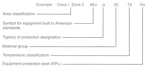
- Class I shall be an optional marking. If it is included in the equipment marking, the Class I marking shall precede the zone marking.
- Zone in accordance with Chapter 9, Table 13.
- Symbol "AEx".
- Protection technique(s) in accordance with Chapter 9, Table 13.
- Applicable material group in accordance with Table 505.9(C)(1) or a specific gas or vapor.
- Temperature classification in accordance with 505.9(D).
- Equipment protection level (EPL).
Exception No. 1: Associated apparatus NOT suitable for installation in a hazardous (classified) location shall be required to be marked only with 505.9(C)(2)(3), (C)(2)(4), and (C)(2)(5), but BOTH the symbol AEx (3) and the symbol for the type of protection (4) shall be enclosed within the same square brackets, for example, [AEx ia Ga] IIC.
Exception No. 2: Simple apparatus as defined in Article 100 shall not be required to have a marked operating temperature or temperature class.
Exception No. 3: Fittings for the termination of cables shall not be required to have a marked operating temperature or temperature class.
Informational Note No. 1: See Informational Note Figure 505.9(C)(2), for an explanation of the marking that is required. An example of the required marking for intrinsically safe apparatus for installation in Zone 0 is "Class I, Zone 0, AEx ia IIC T6 Ga" or "Zone 0, AEx, ia, IIC T6 Gb."
Informational Note No. 2: An example of the required marking for intrinsically safe associated apparatus mounted in a flameproof enclosure for installation in Zone 1 is "Class I, Zone 1 AEx db[ia] IIC T4 Gb" or "Zone 1, AEx, db[ia Ga] IIC T4 Gb."
Informational Note No. 3: An example of the required marking for intrinsically safe associated apparatus NOT for installation in a hazardous (classified) location is "[AEx ia Ga] IIC."
Informational Note No. 4: EPLs are designated as G for gas, or D for dust, and are then followed by a letter (a, b, or c) to give the user a better understanding as to whether the equipment provides (a) a "very high," (b) a "high," or (c) an "enhanced" level of protection against ignition of an explosive atmosphere. For example, a Zone 1, AEx db IIC T4 Gb motor (which is suitable by protection concept for application in Zone 1) is marked with an EPL of "Gb" to indicate that it was provided with a high level of protection.
Informational Note No. 5: See ANSI/UL 60079-26, Explosive Atmospheres - Part 26: Equipment with Equipment Protection Level (EPL) Ga, for additional information. Equipment installed outside a Zone 0 location and electrically connected to equipment located inside a Zone 0 location might be marked Zone 0/1. The "/" indicates that equipment contains a separation element and can be installed at the boundary between a Zone 0 and a Zone 1 location.
(D) Temperature Classification Marking.
The temperature marking shall not exceed the autoignition temperature of the specific gas or vapor to be encountered.
Informational Note No. 1: See ANSI/UL 60079-26, Explosive Atmospheres - Part 26: Equipment with Equipment Protection Level (EPL) Ga, for more information. Equipment installed outside a Zone 0 location and electrically connected to equipment located inside a Zone 0 location might be marked Zone 0/1. The "/'' indicates that equipment contains a separation element and can be installed at the boundary between a Zone 0 and a Zone 1 location.
Equipment shall be marked to show the operating temperature or temperature class referenced to a 40°C ambient, or at the higher ambient temperature if the equipment is rated and marked for an ambient temperature of greater than 40°C. The temperature class, if provided, shall be indicated using the temperature class (T code) shown in Table 505.9(D).
Electrical equipment designed for use in the ambient temperature range between —20°C and +40°C shall require no ambient temperature marking.
Electrical equipment that is designed for use in a range of ambient temperatures other than —20°C to +40°C is considered to be special; and the ambient temperature range shall then be marked on the equipment, including either the symbol "Ta" or "Tamb" together with the special range of ambient temperatures, in degrees Celsius.
Informational Note No. 2: For example, such a marking might be "—30°C to +40°C."
Exception No. 1: Equipment of the non-heat-producing type, such as conduit fittings, and equipment of the heat-producing type having a maximum temperature of not more than 100°C (212°F) shall not be required to have a marked operating temperature or temperature class.
Exception No. 2: Equipment identified for Class I, Division 1 or Division 2 locations as permitted by 505.20(A), (B), and (C) shall be permitted to be marked in accordance with 505.8(C) and Table 500.8(C)(4).
Table 505.9(D) Temperature Classification Marking of Maximum Surface Temperature for Group II Electrical Equipment.
| Temperature Class (T Code) |
Maximum Surface Temperature (°C) |
|---|---|
| T1 | ≤450 |
| T2 | ≤300 |
| T3 | ≤200 |
| T4 | ≤135 |
| T5 | ≤100 |
| T6 | ≤85 |
(E) Threading.
The supply connection entry thread form shall be NPT or metric. Conduit and fittings shall be made wrench-tight to prevent sparking when fault current flows through the conduit system, and to ensure the explosionproof or flameproof integrity of the conduit system where applicable. Equipment provided with threaded entries for field wiring connections shall be installed in accordance with 505.9(E)(1) or (E)(2) and with (E)(3).
(1) Equipment Provided With Threaded Entries for NPT Threaded Conduit or Fittings.
For equipment provided with threaded entries for NPT threaded conduit or fittings, listed conduit, listed conduit fittings, or listed cable fittings shall be used.
All NPT threaded conduit and fittings shall be threaded with a National (American) Standard Pipe Taper (NPT) thread.
NPT threaded entries into explosionproof or flameproof equipment shall be made up with at least five threads fully engaged.
Exception: For listed explosionproof or flameproof equipment, factory-threaded NPT entries shall be made up with at least 41/2 threads fully engaged.
Informational Note No. 1: See ASME B1.20.1, Pipe Threads, General Purpose (Inch), for thread specifications for male NPT threads.
Informational Note No. 2: See ANSI/UL 60079-1, Explosive Atmospheres - Part 1: Equipment Protection by Flameproof Enclosures"d", and ASME B1.20.1, Pipe Threads, General Purpose (Inch), for information on female NPT threaded entries using modified National Standard Pipe Taper (NPT) thread.
(2) Equipment Provided With Threaded Entries for Metric Threaded Conduit or Fittings.
For equipment with metric threaded entries, listed conduit fittings or listed cable fittings shall be used. Such entries shall be identified as being metric, or listed adapters to permit connection to conduit or NPT threaded fittings shall be provided with the equipment and shall be used for connection to conduit or NPT threaded fittings.
Metric threaded fittings installed into explosionproof or flameproof equipment entries shall have a class of fit of at least 6g/6H and be made up with at least five threads fully engaged.
Informational Note: See ISO 965-1, ISO general purpose metric screw threads - Tolerances - Part 1: Principles and basic data, and ISO 965-3, ISO general purpose metric screw threads - Tolerances - Part 3: Deviations for constructional screw threads, for threading specifications for metric threaded entries.
(3) Unused Openings.
All unused openings shall be closed with blanking elements or close-up plugs that are listed for the location and will maintain the type of protection. Thread engagement shall comply with 505.9(E)(1) or (E)(2).
(G) Equipment Involving Optical Radiation.
For equipment involving sources of optical radiation (such as laser or LED sources) in the wavelength range from 380 nm to 10 pm, the risk of ignition from optical radiation shall be considered for all electrical parts and circuits that may be exposed to the radiation, both inside and outside the optical equipment. This includes optical equipment, which itself is located outside the explosive atmosphere, but its emitted optical radiation enters such atmospheres.
Informational Note: See ANSI/UL 60079-28, Explosive Atmospheres - Part 28: Protection of Equipment and Transmission Systems Using Optical Radiation, for information on types of protection to minimize the risk of ignition in explosive atmospheres from optical radiation.
Exception: All luminaires (fixed, portable, or transportable) and hand lights, intended to be supplied by mains (with or without galvanic isolation) or powered by batteries, with any continuous divergent light source, including LEDs, shall be excluded from this requirement.
505.15 Wiring Methods.
Wiring methods shall maintain the integrity of protection techniques and shall comply with 505.15(A) through (C).
(B) Zone 1.
(1) General.
In Zone 1 locations, the following wiring methods shall be permitted:
Informational Note No. 1: See Article 100 for the definition of restricted industrial establishment [as applied to hazardous (classified) locations].
- All wiring methods permitted by 505.15(A).
- In restricted industrial establishments where the cable is not subject to physical damage, Type MC-HL cable listed for use in Zone 1 or Class I, Division 1 locations, with a gas/vaportight continuous corrugated metallic sheath, an overall jacket of suitable polymeric material, and a separate equipment grounding conductor(s) in accordance with 250.122. Type MC-HL cable shall be terminated with fittings listed for the application and installed in accordance with Part II of Article 330.
- In restricted industrial establishments where the cable is not subject to physical damage, Type ITC-HL cable listed for use in Zone 1 or Class I, Division 1 locations, with a gas/vaportight continuous corrugated metallic sheath and an overall jacket of suitable polymeric material. Type ITC-HL cable shall be terminated with fittings listed for the application and installed in accordance with 335.4
- Type MI cable terminated with fittings listed for Zone 1 or Class I, Division 1 locations. Type MI cable shall be installed and supported in a manner to avoid tensile stress at the termination fittings.
- Threaded rigid metal conduit (RMC) or threaded intermediate metal conduit (IMC), including RMC or IMC conduit systems with supplemental corrosion protection coatings.
- Where encased in a concrete envelope a minimum of 50 mm (2 in.) thick and provided with not less than 600 mm (24 in.) of cover measured from the top of the conduit to grade, PVC or RTRC conduit. RMC or IMC conduit shall be used for the last 600 mm (24 in.) of the underground run to emergence or to the point of connection to the aboveground raceway. An equipment grounding conductor shall be included to provide for electrical continuity of the raceway system and for grounding of non—current-carrying metal parts.
- Intrinsic safety type of protection "ib" using the wiring methods in accordance with 504.20.
- Optical fiber cable Type OFNP, Type OFCP, Type OFNR, Type OFCR, Type OFNG, Type OFCG, Type OFN, or Type OFC installed in raceways in accordance with 505.15(B). Optical fiber cable shall be sealed in accordance with 505.16.
- In restricted industrial establishments for applications limited to 600 volts nominal or less where the cable is not subject to physical damage, Type TC-ER-HL shall be terminated with fittings listed for the location and installed in accordance with 336.10.
- In restricted industrial establishments, listed Type P cable with metal braid armor and an overall jacket. Type P cable shall be terminated with fittings listed for the location and installed in accordance with Part II of Article 337.
Informational Note No. 3: See UL 1309A, Outline of Investigation for Cable for use in Mobile Installations, for information on construction, testing, and marking of Type P cable.
(2) Flexible Connections.
If flexibility is necessary to minimize the transmission of vibration from equipment during operation or to allow for movement after installation during maintenance, one of the following shall be permitted:
- Flexible fittings listed for the location.
- Flexible cord in accordance with 505.17(A), terminated with cord connectors listed for the location.
- In restricted industrial establishments for applications limited to 600 volts nominal or less, where the cable is not subject to physical damage and is terminated with fittings listed for the location, Type TC-ER-HL cable. Type TC-ER-HL cable shall be listed for use in Class I, Division 1 or Zone 1 locations and shall be installed in accordance with 336.10.
- In restricted industrial establishments listed Type P cable with metal braid armor and an overall jacket. Type P cable shall be terminated with fittings listed for the location and installed in accordance with Part II of Article 337.
Informational Note No. 2: See UL 1309A, Outline of Investigation for Cable for Use in Mobile Installations, for information on construction, testing, and marking of Type P cable.
(C) Zone 2.
(1) General.
In Zone 2 locations, the following wiring methods shall be permitted:
Informational Note No. 1: See Article 100 for the definition of restricted industrial establishment [as applied to hazardous (classified) locations].
- All wiring methods permitted by 505.15(B).
- Type MCI, Type MV, Type TC, or Type TC-ER cable, including installation in cable tray systems. Type TC-ER shall include a separate equipment grounding conductor in addition to a drain wire that might be present. The cable shall be terminated with listed fittings. Single conductor Type MV cables shall be shielded or metallic-armored.
- Type ITC cable or Type ITC-ER cable as permitted in 335.4 and terminated with listed fittings. Type ITC-ER shall include a separate insulated equipment grounding conductor in addition to a drain wire.
- Type PLTC cable or Type PLTC-ER cable used for Class 2 or Class 3 circuits, including installation in cable tray systems. The cable shall be terminated with listed fittings. Type PLTC-ER shall include a separate insulated equipment grounding conductor in addition to a drain wire that might be present.
- Enclosed gasketed busways or enclosed gasketed wire-ways.
- In restricted industrial establishments and where metal conduit does not provide the corrosion resistance needed for the environment where it is installed, listed reinforced thermosetting resin conduit (RTRC), factory elbows, and associated fittings, all marked with the suffix -XW, and Schedule 80 PVC conduit, factory elbows, and associated fittings. Where seals are required for boundary conditions as defined in 505.16(C)(1)(b), the Zone 1 wiring method shall extend into the Zone 2 area to the seal, which shall be located on the Zone 2 side of the Zone 1/Zone 2 boundary.
- Intrinsic safety type of protection "ic" using any of the wiring methods permitted for unclassified locations. Intrinsic safety type of protection "ic" systems shall be installed in accordance with the control drawing(s). Simple apparatus, not shown on the control drawing, shall be permitted in an intrinsic safety type of protection "ic" circuit if the simple apparatus does not interconnect the intrinsic safety type of protection "ic" systems to any other circuit. Separate intrinsic safety type of protection "ic" systems shall be installed in accordance with one of the following:
- In separate cables
- In multiconductor cables where the conductors of each circuit are within a grounded metal shield
- In multiconductor cables where the conductors of each circuit have insulation with a minimum thickness of 0.25 mm (0.01 in.)Informational Note No. 2: See Article 100 for the definition of simple apparatus.
- Optical fiber cable of Type OFNP, Type OFCP, Type OFNR, Type OFCR, Type OFNG, Type OFCG, Type OFN, or Type OFC installed in cable trays or any other raceway in accordance with 505.15(C). Optical fiber cable shall be sealed in accordance with 505.16.
- Cablebus.
- In restricted industrial establishments, listed Type P cable with or without metal braid armor and an overall jacket. Type P cable shall be terminated with fittings listed for the location and installed in accordance with Part II of Article 337.
Informational Note No. 3: See UL 1309A, Outline of Investigation for Cable for Use in Mobile Installations, for information on construction, testing, and marking of Type P cable.
(2) Flexible Connections.
Where flexibility is necessary to minimize the transmission of vibration from equipment during operation or to allow for movement after installation during maintenance, one or more of the following wiring methods shall be permitted:
- Listed flexible metal fittings
- Flexible metal conduit with listed fittings
- Interlocked armor Type MC cable with listed fittings
- Type P cable
- Type TC-ER or Type TC-ER-HL cable
- Type ITC-ER or Type ITC-HL cable
- Type PLTC-ER cable
- Liquidtight flexible metal conduit with listed fittings
- Liquidtight flexible nonmetallic conduit with listed fittings
- Flexible cord in accordance with 505.17, terminated with a listed cord connector that maintains the type of protection of the terminal compartment
- For elevator use, an identified elevator cable of Type EO, Type ETP, or Type ETT, shown under the "use" column in Table 400.4 for "hazardous (classified) locations" and terminated with listed fittings
505.16 Sealing and Drainage.
Seals in conduit and cable systems shall comply with 505.16(A) through (E). Sealing compound shall be used in Type MI cable termination fittings to exclude moisture and other fluids from the cable insulation.
Informational Note No. 1: See 505.16(C)(2)(c). Seals are provided in conduit and cable systems to minimize the passage of gases and vapors and prevent the passage of flames from one portion of the electrical installation to another through the conduit. Such communication through Type VII cable is inherently prevented by construction of the cable. Unless specifically designed and tested for the purpose, conduit and cable seals are not intended to prevent the passage of liquids, gases, or vapors at a continuous pressure differential across the seal. Even at differences in pressure across the seal equivalent to a few inches of water, there might be a slow passage of gas or vapor through a seal and through conductors passing through the seal.
Informational Note No. 2: See 505.16(D)(2). Temperature extremes and highly corrosive liquids and vapors can affect the ability of seals to perform their intended function.
Informational Note No. 3: Gas or vapor leakage and propagation of flames might occur through the interstices between the strands of standard stranded conductors larger than 2 AWG. Special conductor constructions, for example, compacted strands or sealing of the individual strands, are means of reducing leakage and preventing the propagation of flames.
(A) Zone 0.
(1) Conduit Seals.
(2) Cable Seals.
Seals shall be provided on cables at the first point of termination after entry into the Zone 0 location.
(3) Not Required to Be Explosionproof or Flameproof.
Seals shall not be required to be explosionproof or flameproof.
(B) Zone 1.
(1) Type of Protection "d", "db", "e", or "eb" Enclosures.
Conduit seals shall be provided within 50 mm (2 in.) for each conduit entering enclosures having type of protection "d", "db", "e", or "eb".
Exception No. 1: Where the enclosure having type of protection "d" or "db" is marked to indicate that a seal is not required.
Exception No. 2: For type of protection "e" or "eb", conduit and fittings employing only NPT to NPT raceway joints or fittings listed for type of protection "e" or "eb" shall be permitted between the enclosure and the seal, and the seal shall not be required to be within 50 mm (2 in.) of the entry.
Informational Note: Examples of fittings employing other than NPT threads include conduit couplings, capped elbows, unions, and breather drains.
Exception No. 3: For conduit installed between type of protection "e" or "eb" enclosures employing only NPT to NPT raceway joints or conduit fittings listed for type of protection "e" or "eb", a seal shall not be required.
(2) Explosionproof Equipment.
Conduit seals shall be provided for each conduit entering explosionproof equipment according to 505.16(B)(2)(a), (B)(2)(b), and (B)(2)(c).
-
In each conduit entry into an explosionproof enclosure where either of the following conditions apply:
-
The enclosure contains apparatus, such as switches, circuit breakers, fuses, relays, or resistors that may produce arcs, sparks, or high temperatures that are considered to be an ignition source in normal operation. For the purposes of this section, high temperatures shall be considered to be any temperatures exceeding 80 percent of the autoignition temperature in degrees Celsius of the gas or vapor involved.Exception: Seals shall not be required for conduit entering an enclosure where such switches, circuit breakers, fuses, relays, or resistors comply with one of the following:
-
The entry is metric designator 53 (trade size 2) or larger and the enclosure contains terminals, splices, or taps.
-
- Conduit seals shall be installed within 450 mm (18 in.) from the enclosure. Only threaded couplings, or explosionproof fittings such as unions, reducers, elbows, and capped elbows that are not larger than the trade size of the conduit, shall be permitted between the sealing fitting and the explosionproof enclosure.
- Where two or more explosionproof enclosures for which conduit seals are required under 505.16(B)(2) are connected by nipples or by runs of conduit not more than 900 mm (36 in.) long, a single conduit seal in each such nipple connection or run of conduit shall be considered sufficient if located not more than 450 mm (18 in.) from either enclosure.
(3) Pressurized Enclosures and Pressurized Rooms.
Conduit seals shall be provided in each conduit entry into a pressurized enclosure or pressurized room where the conduit is not pressurized as part of the protection system. Conduit seals shall be installed within 450 mm (18 in.) from the pressurized enclosure or pressurized room.
Informational Note No. 1: Installing the seal as close as possible to the enclosure reduces problems with purging the dead airspace in the pressurized conduit.
Informational Note No. 2: See NFPA 496, Standard for Purged and Pressurized Enclosures for Electrical Equipment, for information on pressurized equipment.
Informational Note No. 3: See UL 60079-13, Explosive Atmospheres - Part 13: Equipment Protection by Pressurized Room "p" and Artificially Ventilated Room "v", for additional information.
(4) Zone 1 Boundary.
Conduit seals shall be provided in each conduit run leaving a Zone 1 location. The sealing fitting shall be permitted on either side of the boundary of such location within 3.05 m (10 ft) of the boundary and shall be designed and installed so as to minimize the amount of gas or vapor within the Zone 1 portion of the conduit from being communicated to the conduit beyond the seal. Except for listed explosionproof reducers at the conduit seal, there shall be no union, coupling, box, or fitting between the conduit seal and the point at which the conduit leaves the Zone 1 location.
Exception: Metal conduit containing no unions, couplings, boxes, or fittings and passing completely through a Zone 1 location with no fittings less than 300 mm (12 in.) beyond each boundary shall not require a conduit seal if the termination points of the unbroken conduit are in unclassified locations.
(5) Cables Capable of Transmitting Gases or Vapors.
Conduits containing cables with a gas/vaportight continuous sheath capable of transmitting gases or vapors through the cable core shall be sealed in the Zone 1 location after removing the jacket and any other coverings so that the sealing compound surrounds each individual insulated conductor or optical fiber tube and the outer jacket.
Exception: Multiconductor cables with a gas/vaportight continuous sheath capable of transmitting gases or vapors through the cable core shall be permitted to be considered as a single conductor by sealing the cable in the conduit within 450 mm (18 in.) of the enclosure and the cable end within the enclosure by an approved means to minimize the entrance of gases or vapors and prevent the propagation of flame into the cable core, or by other approved methods. For shielded cables and twisted pair cables, it shall not be required to remove the shielding material or separate the twisted pair.
(7) Cables Entering Enclosures.
Cable seals shall be provided for each cable entering flameproof or explosionproof enclosures. The seal shall comply with 505.16(D).
(C) Zone 2.
(1) Conduit Seals.
Conduit seals shall be provided in accordance with 505.16(C)(1)(a) through (C)(1)(f).
- Flameproof and Explosionproof Enclosures. Conduit seals shall be required for connections to enclosures that are required to be flameproof or explosionproof, in accordance with 505.16(B)(1) and (B)(2). All portions of the conduit run or nipple between the seal and enclosure shall comply with 505.16(B).
- Conduits Between Zone 2 and Unclassified Locations. Conduit seals shall be required in each conduit run passing from a Zone 2 location into an unclassified location. The conduit seals and conduit run shall comply with all the following:
- The sealing fitting shall be permitted on either side of the boundary of the location within 3.05 m (10 ft) of the boundary.
- The sealing fitting shall be designed and installed to minimize the amount of gas or vapor within the Zone 2 portion of the conduit from being communicated to the conduit beyond the seal.
- Threaded rigid metal conduit (RMC) or threaded intermediate metal conduit (IMC) shall be used between the sealing fitting and the point at which the conduit leaves the Zone 2 location, and a threaded connection shall be used at the sealing fitting.
- There shall be no union, coupling, box, or fitting between the conduit seal and the point at which the conduit leaves the Zone 2 location except for listed explosionproof reducers at the conduit seal.
- Conduits shall be sealed to minimize the amount of gas or vapor within the Zone 2 portion of the conduit from being communicated to the conduit beyond the seal.
- Such seals shall not be required to be flameproof or explosionproof but shall be identified for the purpose of minimizing passage of gases under normal operating conditions and shall be accessible.
- Conduits Passing Through a Zone 2 Location. Metal conduit containing no unions, couplings, boxes, or fittings and passing completely through a Zone 2 location with no fittings less than 300 mm (12 in.) beyond each boundary shall not be required to be sealed if the termination points of the unbroken conduit are in unclassified locations.
- Conduit Systems Ending in an Unclassified Location. Conduit systems terminating in an unclassified location where a wiring method transition is made to cable tray, cablebus, ventilated busway, Type MI cable, or cable that is not installed in a raceway or cable tray system shall not be required to be sealed where passing from the Zone 2 location into the unclassified location. The unclassified location shall be outdoors or, if the conduit system is all in one room, it shall be permitted to be indoors. The conduits shall not terminate at an enclosure containing an ignition source in normal operation.
- Pressurized Enclosures or Pressurized Rooms. Conduit systems passing from enclosures or rooms that permit general-purpose equipment as a result of pressurization into a Zone 2 location shall not require a seal at the boundary.Informational Note: See NFPA 496, Standard for Purged and Pressurized Enclosures for Electrical Equipment, for information on purged and pressurized equipment.
- Outdoor Conduit System Segments. Segments of above-ground conduit systems shall not be required to be sealed where passing from a Zone 2 location into an unclassified location if all the following conditions are met:
- The conduit system segment shall not pass through a Zone 0 or Zone 1 location where the conduit contains unions, couplings, boxes, or fittings within 300 mm (12 in.) of the Zone 0 or Zone 1 location.
- The conduit system segment shall be located entirely in an outdoor location.
- The conduit system segment shall not be directly connected to canned pumps, process or service connections for flow, pressure, or analysis measurement, and so forth, that depend on a single compression seal, diaphragm, or tube to prevent flammable or combustible fluids from entering the conduit system.
- The conduit system segment shall only have threaded rigid metal conduit (RMC) and threaded intermediate metal conduit (IMC) with threaded unions, couplings, conduit bodies, and fittings in the unclassified location.
- The conduit system segment shall be sealed at its entry to each enclosure or fitting housing terminals, splices, or taps in Zone 2 locations.
(2) Cable Seals.
Cable seals shall be installed in accordance with 505.16(C)(2)(a) through (C)(2)(c).
- Explosionproof and Flameproof Enclosures. Cables entering enclosures required to be flameproof or explosionproof shall be sealed at the point of entrance. The seal shall comply with 505.16(D). Multiconductor or optical multifiber cables with a gas/vaportight continuous sheath capable of transmitting gases or vapors through the cable core shall be sealed in the Zone 2 location after removing the jacket and any other coverings so that the sealing compound surrounds each individual insulated conductor or optical fiber tube to minimize the passage of gases and vapors. Multiconductor or optical multifiber cables in conduit shall be sealed as described in 505.16(B)(4).
- Restricted Breathing Enclosures "nR". Cables entering restricted breathing enclosures required to be restricted breathing shall be sealed at the point of entrance into the enclosure. These seals shall be installed in accordance with 505.16(D). Multiconductor cables or multifiber optical fiber cables with a gas/vaportight continuous sheath capable of transmitting gases or vapors through the cable core shall be sealed in the Zone 2 location. The jacket and any other coverings shall be removed to allow the sealing compound to surround each individual insulated conductor or optical fiber tube to minimize the passage of gases and vapors. Multiconductor cables or optical fiber cables in conduit shall be sealed as described in 505.16(C)(1)(b).Exception No. 1: Cables passing from an enclosure or room that is unclassified as a result of Type Z pressurization into a Zone 2 location shall not require a seal at the boundary.Exception No. 2: Shielded cables and twisted pair cables terminated with fittings listed for the location shall not require removal of the shielding material or separation of the twisted pairs.
- Cables That Will Not Transmit Gases or Vapors. Cables with a gas/vaportight continuous sheath that will not transmit gases or vapors through the cable core in excess of the quantity permitted for seal fittings shall not be required to be sealed except as required in 505.16(C)(2)(b). The minimum length of such cable run shall not be less than the length that limits gas or vapor flow through the cable core to the rate permitted for seal fittings [200 cm3/hr (0.007 ft3/hr) of air at a pressure of 1500 pascals (6 in. of water)].Informational Note No. 1: See ANSI/UL 2225, Cables and Cable-Fittings for Use in Hazardous (Classified) Locations, for further information on construction, testing, and marking of cables, cable fittings, and cord connectors.Informational Note No. 2: The cable core does not include the interstices of the conductor strands.
- Cables Capable of Transmitting Gases or Vapors. Cables with a gas/vaportight continuous sheath capable of transmitting gases or vapors through the cable core shall not be required to be sealed except as required in 505.16(C)(2)(b), unless the cable is attached to process equipment or devices that might cause a pressure in excess of 1500 pascals (6 in. of water) to be exerted at a cable end, in which case a seal, barrier, or other means shall be provided to prevent migration of flammables into an unclassified area.Exception: Cables with an unbroken gas/vaportight continuous sheath shall be permitted to pass through a Zone 2 location without seals.
- Cables Without a Gas/Vaportight Continuous Sheath. Cables that do not have a gas/vaportight continuous sheath shall be sealed at the boundary of the Zone 2 and unclassified location to minimize the passage of gases or vapors into an unclassified location.
Informational Note: The cable sheath can be either metal or a nonmetallic material.
(D) Zones 0, 1, and 2.
(1) Fittings.
Enclosures for connections or equipment shall be provided with an integral means for sealing, or sealing fittings listed for the location shall be used. Sealing fittings shall be listed for use with one or more specific compounds and shall be accessible.
(2) Compound.
The compound shall provide a seal against passage of gas or vapors through the seal fitting, shall not be affected by the surrounding atmosphere or liquids, and shall not have a melting point less than 93°C (200°F).
(3) Thickness of Compounds.
In a completed seal, the minimum thickness of the sealing compound shall not be less than the trade size of the sealing fitting and, in no case, less than 16 mm (5/8 in.).
(5) Conductor or Optical Fiber Fill.
The cross-sectional area of the conductors or optical fiber tubes (metallic or nonmetallic) permitted in a seal shall not exceed 25 percent of the cross-sectional area of a rigid metal conduit of the same trade size unless it is specifically listed for a higher percentage of fill.
(E) Drainage.
(1) Control Equipment.
Where there is a probability that liquid or other condensed vapor may be trapped within enclosures for control equipment or at any point in the raceway system, approved means shall be provided to prevent accumulation or to permit periodic draining of such liquid or condensed vapor.
(2) Motors and Generators.
Where liquid or condensed vapor may accumulate within motors or generators, joints and conduit systems shall be arranged to minimize entrance of liquid. If means to prevent accumulation or to permit periodic draining are necessary, such means shall be provided at the time of manufacture and shall be considered an integral part of the machine.
505.17 Flexible Cables, Cords and Connections.
(A) Flexible Cords, Zone 1 and Zone 2.
A flexible cord shall be permitted for connection between portable lighting equipment or other portable utilization equipment and the fixed portion of their supply circuit. Flexible cord shall also be permitted in restricted industrial establishments for any segment of the circuit where installation of one of the fixed wiring methods of 505.15(B) and (C) will not provide the flexibility needed to minimize the transmission of vibration from equipment during operation or to allow for movement after installation during maintenance operations. The flexible cord shall be protected against physical damage and be continuous for the entire length of the cord from equipment connection to equipment connection. Where flexible cords are used, the cords shall comply with the following:
- Be of a type listed for extra-hard usage
- Contain, in addition to the conductors of the circuit, an equipment grounding conductor complying with 400.23
- Be connected to terminals or to supply conductors in an approved manner
- Be supported by clamps or by other suitable means in such a manner that there will be no tension on the terminal connections
- Where the flexible cord enters boxes, fittings, or enclosures that are required to be explosionproof or flameproof, be terminated with a listed cord connector that maintains the type of protection
- Where entering an increased safety "e" enclosure, be terminated with a listed increased safety "e" cord connector
Informational Note No. 1: See 400.10 for permitted uses of flexible cords.
Informational Note No. 2: See Article 100 for the definition of restricted industrial establishment [as applied to hazardous (classified) locations].
Electric submersible pumps with means for removal without entering the wet-pit shall be considered portable utilization equipment. The extension of the flexible cord within a suitable raceway between the wet-pit and the power source shall be permitted.
Electric mixers intended for travel into and out of open-type mixing tanks or vats shall be considered portable utilization equipment.
Informational Note No. 3: See 505.18 for flexible cords exposed to liquids having a deleterious effect on the conductor insulation.
(B) Instrumentation Connections for Zone 2.
To facilitate replacements, process control instruments shall be permitted to be connected through flexible cords, attachment plugs, and receptacles, provided that all of the following conditions apply:
- A switch listed for Zone 2 is provided so that the attachment plug is not depended on to interrupt current, unless the circuit is type "ia," "ib," or "ic" protection, in which case the switch is not required.
- The current does not exceed 3 amperes at 120 volts, nominal.
- The power-supply cord does not exceed 900 mm (3 ft), is of a type listed for extra-hard usage or for hard usage if protected by location, and is supplied through an attachment plug and receptacle of the locking and grounding type.
- Only necessary receptacles are provided.
- The receptacle carries a label warning against unplugging under load.
505.18 Conductors and Conductor Insulation.
(B) Conductor Insulation.
Where condensed vapors or liquids may collect on, or come in contact with, the insulation on conductors, such insulation shall be of a type identified for use under such conditions, or the insulation shall be protected by a sheath of lead or by other approved means.
505.19 Uninsulated Exposed Parts.
There shall be no uninsulated exposed parts, such as electrical conductors, buses, terminals, or components, that operate at more than 30 volts (15 volts in wet locations). These parts shall additionally be protected by type of protection "ia", "ib", or "ic" that is suitable for the location.
505.20 Equipment Requirements.
(A) Zone 0.
In Zone 0 locations, only equipment specifically listed and marked as suitable for the location shall be permitted.
Exception: Intrinsically safe apparatus listed for use in Class I, Division 1 locations for the same gas, or as permitted by 505.9(B)(2), and with a suitable temperature class shall be permitted.
(B) Zone 1.
In Zone 1 locations, only equipment specifically listed and marked as suitable for the location shall be permitted.
Exception No. 1: Equipment identified for use in Class I, Division 1 or listed for use in Zone 0 locations for the same gas, or as permitted by 505.9(B)(2), and with a suitable temperature class shall be permitted.
(C) Zone 2.
In Zone 2 locations, only equipment specifically listed and marked as suitable for the location shall be permitted.
Exception No. 1: Equipment listed for use in Zone 0 or Zone 1 locations for the same gas, or as permitted by 505.9(B)(2), and with a suitable temperature class shall be permitted.
Exception No. 2: Equipment identified for Zone 1 or Zone 2 type of protection "p" shall be permitted.
Exception No. 3: Equipment identified for use in Class I, Division 1 or Division 2 locations for the same gas, or as permitted by 505.9(B)(2), and with a suitable temperature class shall be permitted.
Exception No. 4: In Zone 2 locations, the installation of open or nonexplosionproof or nonflameproof enclosed motors such as squirrel-cage induction motors without brushes, switching mechanisms, or similar arc-producing devices that are not identified for use in a Zone 2 location shall be permitted.
Exception No. 5: The exposed surface of space heaters used to reduce condensation of moisture during shutdown periods shall not exceed 80 percent of the autoignition temperature in degrees Celsius of the gas or vapor involved when operated at rated voltage, and the maximum space heater surface temperature [based on a 40°C or higher marked ambient] shall be permanently marked on a visible nameplate mounted on the motor. Otherwise, space heaters shall be identified for Class I, Division 2 or Zone 2 locations.
Exception No. 6: A sliding contact shaft bonding device used for the purpose of maintaining the rotor at ground potential shall be permitted where the potential discharge energy is determined to be nonincendive for the application. The shaft bonding device shall be permitted to be installed on the inside or the outside of the motor.
Informational Note No. 1: It is important to consider the temperature of internal and external surfaces that might be exposed to the flammable atmosphere.
Informational Note No. 2: It is important to consider the risk of ignition due to currents arcing across discontinuities and overheating of parts in multi-section enclosures of large motors and generators. Such motors and generators might need equipotential bonding jumpers across joints in the enclosure and from enclosure to ground. Where the presence of ignitible gases or vapors is suspected, clean air purging might be needed immediately prior to and during start-up periods.
Informational Note No. 3: See IEEE STD 1349, IEEE Guide for the Application of Electric Machines in Zone 2 and Class I, Division 2 Hazardous (Classified) Locations, for information on the application of rotating electric machines including shaft bonding devices and potential discharge energy calculations.
(D) Materials.
Equipment marked Group IIC shall be permitted for applications requiring Group IIA or Group IIB equipment. Similarly, equipment marked Group IIB shall be permitted for applications requiring Group IIA equipment.
Equipment marked for a specific gas or vapor shall be permitted for applications where the specific gas or vapor may be encountered.
505.22 Increased Safety "e" Motors and Generators.
In Zone 1 locations, increased safety "e" motors and generators of all voltage ratings shall be listed for Zone 1 locations, and shall comply with all of the following:
- Motors shall be marked with the current ratio, IA/IN, and time, tE.
- Motors shall have controllers marked with the model or identification number, output rating (horsepower or kilowatt), full-load amperes, starting current ratio (IA/IN), and time (tE) of the motors that they are intended to protect; the controller marking shall also include the specific overload protection type (and setting, if applicable) that is listed with the motor or generator.
- Connections shall be made with the specific terminals listed with the motor or generator.
- Terminal housings shall be permitted to be of substantial, nonmetallic, nonburning material, provided an internal grounding means between the motor frame and the equipment grounding connection is incorporated within the housing.
- The provisions of Part III of Article 430 shall apply regardless of the voltage rating of the motor.
- The motors shall be protected against overload by a separate overload device that is responsive to motor current. This device shall be selected to trip or shall be rated in accordance with the listing of the motor and its overload protection.
- Sections 430.32(C) and 430.44 shall not apply to such motors.
- The motor overload protection shall not be shunted or cut out during the starting period.
Informational Note: See ANSI/UL 122001, General Requirements for Electrical Ignition Systems for Internal Combustion Engines in Class I, Division 2 or Zone 2, Hazardous (Classified) Locations, for information on ignition systems for reciprocating engines installed in Zone 2 hazardous (classified) locations. Reciprocating engine—driven generators, compressors, and other equipment installed in Zone 2 locations might present a risk of ignition of flammable materials associated with fuel, starting, and compression due to inadvertent release or equipment malfunction by the engine ignition system and controls.
505.26 Process Sealing.
Process-connected equipment including, but not limited to, canned pumps, submersible pumps, and flow, pressure, temperature, or analysis measurement instruments shall be sealed with a process seal to prevent the migration of process fluids from the designed containment into the external electrical system. Process-connected electrical equipment that incorporates a single process seal, such as a single compression seal, diaphragm, or tube to prevent flammable or combustible fluids from entering a conduit or cable system capable of transmitting fluids, shall be provided with an additional means to mitigate a single process seal failure. The additional means might include, but is not limited to, the following:
- A suitable barrier meeting the process temperature and pressure conditions to which the barrier is subjected upon failure of the single process seal. There shall be a vent or drain between the single process seal and the suitable barrier. Indication of the single process seal failure shall be provided by visible leakage, an audible whistle, or other means of monitoring.
- A listed Type MI cable assembly, rated at not less than 125 percent of the process pressure and not less than 125 percent of the maximum process temperature (in degrees Celsius), installed between the cable or conduit and the single process seal.
- A drain or vent located between the single process seal and a conduit or cable seal. The drain or vent shall be sufficiently sized to prevent overpressuring the conduit or cable seal above 6 in. water column (1493 Pa). Indication of the single process seal failure shall be provided by visible leakage, an audible whistle, or other means of monitoring.
- An add-on secondary seal marked "secondary seal" and rated for the pressure and temperature conditions to which it will be subjected upon failure of the single process seal.
Process-connected electrical equipment that does not rely on a single process seal or is listed and marked "single seal", "dual seal", or "dual seal without annunciation" shall not be required to be provided with an additional means of sealing.
Process-connected electrical equipment marked "single seal - install conduit or cable seal" shall be sealed in accordance with 505.16.
Informational Note: See ANSI/UL 122701, Requirements for Process Sealing Between Electrical Systems and Flammable or Combustible Process Fluids, for construction and testing requirements for process sealing of listed and marked single seal, dual seal, or secondary seal equipment.
505.30 Grounding and Bonding.
Regardless of the voltage of the electrical system, wiring systems and equipment shall comply with 505.30(A) and (B).
(A) Grounding.
Wiring systems and equipment shall be grounded in accordance with Part I and Part VI of Article 250, as applicable.
(B) Bonding.
Wiring systems and equipment shall be bonded in accordance with Part I and Part V of Article 250, as applicable, and 505.30(B)(1) and (B)(2).
(1) Specific Bonding Means.
Bonding shall comply with 505.30(B)(1)(a) and (B)(1)(b).
- The locknut-bushing and double-locknut types of contacts shall not be depended on for bonding purposes, but bonding jumpers with identified fittings or other approved means of bonding shall be used. These bonding means shall apply to all metal raceways, fittings, boxes, cable trays, and enclosures, and other parts of raceway systems between hazardous (classified) locations and the point of grounding for service equipment or point of grounding for a separately derived system. Metal struts, angles, or channels provided for support and mechanical or physical protection as permitted in 335.4(5), 336.10(7)(c), or 722.135(C) shall be bonded in accordance with 250.102.
- Where the branch-circuit overcurrent protection is located on the load side of the disconnecting means, the specific bonding means shall be permitted to end at the nearest point where the grounded circuit conductor and the grounding electrode conductor are connected together on the line side of the building or structure disconnecting means as specified in 250.32(B).
(2) Flexible Metal Conduit and Liquidtight Flexible Metal Conduit.
Flexible metal conduit and liquidtight flexible metal conduit shall comply with 505.30(B)(2)(a) and (B)(2)(b).
- Flexible metal conduit and liquidtight flexible metal conduit shall include an equipment bonding jumper of the wire type in accordance with 250.102.
- In Zone 2 locations, the bonding jumper shall not be required where all of the following conditions are met:
- Listed liquidtight flexible metal conduit 1.8 m (6 ft) or less in length, with fittings listed for grounding, is used.
- Overcurrent protection in the circuit is limited to 10 amperes or less.
- The load is part of a meter, instrument, or relay circuit.
Article 506
Zone 20, 21, and 22 Locations for Combustible Dusts or Ignitible Fibers/Flyings
506.1 Scope.
(A) Covered.
This article covers the requirements for the zone classification system for electrical and electronic equipment and wiring for all voltages where fire and explosion hazards might exist due to combustible dusts, combustible fibers/flyings, or ignitible fibers/flyings for the following:
- Zone 20 hazardous (classified) locations
- Zone 21 hazardous (classified) locations
- Zone 22 hazardous (classified) locations
Informational Note No. 1: See 505.20 or 505.22 for Zone 0, Zone 1, or Zone 2 hazardous (classified) locations where fire or explosion hazards might exist due to flammable gases, flammable vapors, or flammable liquids.
Informational Note No. 2: Zone 20, Zone 21, and Zone 22 area classifications are based on the modified IEC area classification system as defined in ANSI/ISA 60079-10-2 (12.10.05), Explosive Atmospheres - Part 10-2: Classification of Areas - Combustible Dust Atmospheres.
Informational Note No. 3: See NFPA 499, Recommended Practice for the Classification of Combustible Dusts and of Hazardous (Classified) Locations for Electrical Installations in Chemical Process Areas, for information regarding classification of hazardous (classified) locations using Zone methodology.
(B) Not Covered.
This article does not cover electrical and electronic equipment and wiring of all voltages in the following:
- Class I, Class II, or Class III, Division 1 or Division 2 hazardous (classified) locations.
- Zone 0, Zone 1, or Zone 2 hazardous (classified) locations.
- Locations subject to the unique risk and explosion hazards associated with explosives, pyrotechnics, or blasting agents.
- Locations where pyrophoric materials are the only materials used or handled.
- Features of equipment that involve nonelectrical potential sources of ignition (e.g., couplings, pumps, gearboxes, brakes, hydraulic and pneumatic motors, fan, engine, compressor).
Informational Note No. 1: Common nonelectrical potential sources of ignition include hot surfaces and mechanically generated sparks.
Informational Note No. 2: See ANSI/UL 80079-36, Explosive Atmospheres - Part 36: Non-Electrical Equipment for Explosive Atmospheres - Basic Method and Requirements, and ANSI/UL 80079-37, Explosive Atmospheres - Part 37: Non-Electrical Equipment for Explosive Atmospheres - Non-Electrical Type of Protection Constructional Safety "c" Control of Ignition Source "b", Liquid Immersion "k", for additional information.
506.4 Documentation.
Areas designated as hazardous (classified) or unclassified locations shall be documented on an area classification drawing and other associated documentation. This documentation shall be made available to the AHJ and to those authorized to design, install, inspect, maintain, or operate electrical equipment.
Informational Note No. 1: See ANSI/UL 60079-28, Explosive Atmospheres - Part 28: Protection of equipment and transmission systems using optical radiation, for information concerning the installation of equipment using optical emissions technology (such as laser equipment) that could potentially become an ignition source in hazardous (classified) locations.
Informational Note No. 2: See IEC/IEEE 60079-30-2, Explosive atmospheres - Part 30-2: Electrical Resistance Trace Heating - Application Guide for Design, Installation and Maintenance, for information on electrical resistance trace heating for hazardous (classified) locations.
Informational Note No. 3: See IEEE 844.2/CSA C293.2, IEEE/CSA Standard for Skin Effect Trace Heating of Pipelines, Vessels, Equipment, and Structures - Application Guide for Design, Installation, Testing, Commissioning, and Maintenance, for information on electric skin effect trace heating for hazardous (classified) locations.
Informational Note No. 4: See IEEE 844.4/CSA C293.4, IEEE/CSA Standard for Impedance Heating of Pipelines and Equipment - Application Guide for Design, Installation, Testing, Commissioning, and Maintenance, for information on electric impedance heating for hazardous (classified) locations.
506.5 Classification of Locations.
(A) Classifications of Locations.
Locations shall be classified on the basis of the properties of the combustible dust, combustible fibers/flyings, or ignitible fibers/flyings that might be present, and the likelihood that a combustible or ignitible concentration or quantity is present. Each room, section, or area shall be considered individually in determining its classification.
(B) Zone 20, Zone 21, and Zone 22 Locations.
Zone 20, Zone 21, and Zone 22 locations are those in which combustible dust, combustible fibers/flyings, or ignitible fibers/flyings are or might be present in the air or in layers, in quantities sufficient to produce explosible or ignitible mixtures. Zone 20, Zone 21, and Zone 22 locations shall include those specified in 506.5(B)(1), (B)(2), and (B)(3).
(1) Zone 20.
A Zone 20 location is a location where one of the following apply:
- Ignitible concentrations of combustible dust, combustible fibers/flyings, or ignitible fibers/flyings are present continuously or for long periods of time.
- Group IIIC combustible dusts are present in hazardous quantities continuously or for long periods of time.
(2) Zone 21.
A Zone 21 location is a location where one of the following apply:
- Ignitible concentrations of combustible dust, combustible fibers/flyings, or ignitible fibers/flyings are likely to exist occasionally under normal operating conditions.
- Ignitible concentrations of combustible dust, combustible fibers/flyings, or ignitible fibers/flyings might exist frequently because of repair or maintenance operations or because of leakage.
- Equipment is operated or processes are carried on of such a nature that equipment breakdown or faulty operations could result in the release of ignitible concentrations of combustible dust, combustible fibers/flyings, or ignitible fibers/flyings and also cause simultaneous failure of electrical equipment in a mode to cause the electrical equipment to become a source of ignition.
- The location is adjacent to a Zone 20 location from which ignitible concentrations of combustible dust, combustible fibers/flyings, or ignitible fibers/flyings could be communicated.Exception: When communication from an adjacent Zone 20 location is minimized by adequate positive pressure ventilation from a source of clean air, and effective safeguards against ventilation failure are provided.
- Group IIIC combustible dusts are present in hazardous quantities occasionally, under normal or abnormal operating conditions, or frequently because of repair or maintenance operations or because of leakage.
Informational Note No. 1: See ANSI/ISA 60079-10-2 (12.10.05), Explosive Atmospheres - Part 10-2: Classification of Areas - Combustible Dust Atmospheres, regarding the classification of Zone 21 locations.
Informational Note No. 2: This classification usually includes the following:
- Locations outside dust containment and in the immediate vicinity of access doors subject to frequent removal or opening for operation purposes when internal combustible mixtures are present
- Locations outside dust containment in the proximity of filling and emptying points, feed belts, sampling points, truck dump stations, belt dump over points, and so on, where no measures are employed to prevent the formation of combustible mixtures
- Locations outside dust containment where dust accumulates and where, due to process operations, the dust layer is likely to be disturbed and form combustible mixtures
- Locations inside dust containment where explosible dust clouds are likely to occur (but neither continuously, nor for long periods, nor frequently), for example, silos (if filled and/or emptied only occasionally) and the dirty side of filters if large self-cleaning intervals are occurring
(3) Zone 22.
A Zone 22 location is a location where one of the following apply:
- Ignitible concentrations of combustible dust, combustible fibers/flyings, or ignitible fibers/flyings are not likely to occur in normal operation and, if they do occur, will only persist for a short period.
- Combustible dust, combustible fibers/flyings, or ignitible fibers/flyings are handled, processed, or used, but the dust or fibers/flyings are normally confined within closed containers of closed systems from which they can escape only as a result of the abnormal operation of the equipment with which the dust or fibers/flyings are handled, processed, or used.
- The location is adjacent to a Zone 21 location, from which ignitible concentrations of combustible dust, combustible fibers/flyings, or ignitible fibers/flyings could be communicated.
Exception No. 1: When communication from an adjacent Zone 21 location is minimized by adequate positive pressure ventilation from a source of clean air, and effective safeguards against ventilation failure are provided.
Exception No. 2: For Group IIIC combustible dusts or metal combustible fibers/flyings, there shall only be Zone 20 or 21 locations.
Informational Note No. 1: See ANSI/ISA 60079-10-2 (12.10.05), Explosive Atmospheres - Part 10-2: Classification of Areas - Combustible Dust Atmospheres, regarding the classification of Zone 22 locations.
- Outlets from bag filter vents (in the event of a malfunction, there can be emission of combustible mixtures)
- Locations near equipment that has to be opened at infrequent intervals or equipment that from experience can easily form leaks where, due to pressure above atmospheric, dust will blow out
- Pneumatic equipment or flexible connections that can become damaged
- Storage locations for bags containing dusty product (failure of bags can occur during handling, causing dust leakage)
- Locations where controllable dust layers are formed that are likely to be raised into explosible dust-air mixtures
Only if the layer is removed by cleaning before hazardous dust-air mixtures can be formed is the area designated unclassified.
506.6 Material Groups.
For the purposes of testing, approval, and area classification, various air mixtures (not oxygen enriched) shall be grouped as follows:
- Group IIIC: Combustible metal dust, including combustible metal fibers/flyings. [499:3.3.8.2.1]
- Group IIIB: Combustible dust other than combustible metal dust. [499:3.3.8.2.2]
- Group IIIA: Combustible fibers/flyings or ignitible fibers/flyings other than metal. [499:3.3.8.2.3]
Informational Note No. 1: Group IIIA materials are larger particle-size Group IIIB materials and do not include metal dust or metal fibers/flyings. [499:A.3.3.8.2.3].
Informational Note No. 2: Examples of ignitible fibers/flyings include rayon, cotton (including cotton linters and cotton waste), sisal, jute, hemp, cocoa fiber, oakum, and baled waste kapok.
Informational Note No. 3: Combustible fibers/flyings include flat platelet-shaped particulates, such as metal flakes, and fibrous board, such as particle board.
506.7 Special Precaution.
This article shall require equipment construction and installation that ensures safe performance under conditions of proper use and maintenance.
(A) Implementation of Zone Classification System.
Classification of areas, engineering and design, selection of equipment and wiring methods, installation, and inspection shall be performed by qualified persons.
(C) Reclassification Permitted.
A Class II or Class III, Division 1 or Division 2 location shall be permitted to be reclassified as a Zone 20, Zone 21, or Zone 22 location if all of the space that is classified because of a single combustible dust, combustible fiber/flying, or ignitible fiber/flying source is reclassified under the requirements of this article.
(D) Simultaneous Presence of Flammable Gases and Combustible Dusts or Fibers/Flyings.
Where flammable gases, combustible dusts, combustible fibers/flyings, or ignitible fibers/flyings are or might be present at the same time, the simultaneous presence shall be considered during the selection and installation of the electrical equipment and the wiring methods, including the determination of the safe operating temperature of the electrical equipment.
506.8 Protection Techniques.
Acceptable protection techniques for electrical and electronic equipment in hazardous (classified) locations shall be as described in 506.8(A) through (P).
Informational Note No. 1: See ANSI/UL 120101, Definitions and Information Pertaining to Electrical Equipment in Hazardous Locations; and ANSI/UL 60079-0, Explosive Atmospheres - Part 0: Equipment - General Requirements, for additional information.
Informational Note No. 2: See Chapter 9, Table 13 for descriptions of subdivisions of protection techniques.
(J) Protection by Electrical Resistance Trace Heating "60079-30-1".
This protection technique shall be permitted for electrical resistance trace heating equipment in Zone 21 or Zone 22 for which it is listed.
(N) Protection by Skin Effect Trace Heating "IEEE 844.1".
This protection technique shall be permitted for skin effect trace heating equipment in Zone 21 or Zone 22 for which it is listed.
506.9 Equipment Requirements.
(A) Suitability.
Suitability of identified equipment shall be determined by one of the following:
- Equipment listing or labeling
- Evidence of equipment evaluation from a qualified testing laboratory or inspection agency concerned with product evaluation
- Evidence acceptable to the authority having jurisdiction such as a manufacturer's self-evaluation or an owner's engineering judgment
(B) Listing.
Equipment that is listed for Zone 20 shall be permitted in a Zone 21 or Zone 22 location of the same combustible dust, combustible fiber/flying, or ignitible fiber/flying. Equipment that is listed for Zone 21 shall be permitted in a Zone 22 location of the same combustible dust, combustible fiber/flying, or ignitible fiber/flying.
(C) Marking.
(1) Division Equipment.
(2) Zone Equipment.
Equipment meeting one or more of the protection techniques described in 506.8 shall be marked with the following in the order shown:
- Zone in accordance with Chapter 9, Table 13
- Symbol "AEx"
- Protection technique(s) in accordance with Chapter 9, Table 13
- Material group in accordance with 506.6
- Maximum surface temperature in accordance with 506.9(D), marked as a temperature value in degrees Celsius, preceded by "T" and followed by the symbol "°C"
- Ambient temperature marking in accordance with 506.9(D)
- Equipment protection level (EPL)
Informational Note: EPLs are designated as G for gas, or D for dust, and are then followed by a letter (a, b, or c) to give the user a better understanding as to whether the equipment provides (a) a "very high," (b) a "high," or (c) an "enhanced" level of protection against ignition of an explosive atmosphere. For example, a Zone 21 AEx pb IIIB T165°C Db motor is marked with an EPL of "Db".
Exception: Associated apparatus NOT suitable for installation in a hazardous (classified) location shall be required, to be marked only with 506.9(C)(2)(2) and (C)(2)(3), and where applicable (C)(2)(4), but BOTH the symbol AEx in 506.9(C)(2)(2) and the symbol for the type of protection in 506.9(C)(2)(3) shall be enclosed within the same square brackets; for example, [AEx ia] IIIC.
(D) Temperature Classifications.
Equipment shall be marked to show the maximum surface temperature referenced to a 40°C ambient, or at the higher marked ambient temperature if the equipment is rated and marked for an ambient temperature of greater than 40°C. For equipment installed in a Zone 20 or Zone 21 location, the operating temperature shall be based on operation of the equipment when blanketed with the maximum amount of dust (or with dust-simulating fibers/flyings) that can accumulate on the equipment. Electrical equipment designed for use in the ambient temperature range between -20°C and +40°C shall require no additional ambient temperature marking. Electrical equipment that is designed for use in a range of ambient temperatures other than -20°C and +40°C is considered to be special, and the ambient temperature range shall then be marked on the equipment, including either the symbol "Ta" or "Tamb" together with the special range of ambient temperatures.
Informational Note: As an example, such a marking might be 30°C < Ta < +40°C."
Exception No. 1: Equipment of the non-heat-producing type, such as conduit fittings, shall not be required to have a marked operating temperature.
Exception No. 2: Equipment identified for Class II, Division 1 or Class II, Division 2 locations as permitted by 506.20(B) and (C) shall be permitted to be marked in accordance with 500.8(C) and Table 500.8(C)(4).
(E) Threading.
The supply connection entry thread form shall be NPT or metric. Conduit and fittings shall be made wrench-tight to prevent sparking when the fault current flows through the conduit system and to ensure the integrity of the conduit system. Equipment provided with threaded entries for field wiring connections shall be installed in accordance with 506.9(E)(1) or (E)(2) and with (E)(3).
(1) Equipment Provided With Threaded Entries for NPT-Threaded Conduit or Fittings.
For equipment provided with threaded entries for NPT-threaded conduit or fittings, listed conduit fittings or listed cable fittings shall be used. All NPT-threaded conduit and fittings shall be threaded with a National (American) Standard Pipe Taper (NPT) thread.
Informational Note: See ASME B1.20.1, Pipe Threads, General Purpose (Inch), for thread specifications for NPT threads.
(2) Equipment Provided With Threaded Entries for Metric-Threaded Fittings.
For equipment with metric-threaded entries, listed conduit fittings or listed cable fittings shall be used. Such entries shall be identified as being metric, or listed adapters to permit connection to conduit or NPT-threaded fittings shall be provided with the equipment and shall be used for connection to conduit or NPT-threaded fittings. Metric-threaded fittings installed into equipment entries shall be made up with at least five threads fully engaged.
(3) Unused Openings.
All unused openings shall be closed with blanking elements or close-up plugs that are listed for the location and will maintain the type of protection. Thread engagement shall comply with the requirements of 506.9(E)(1) or (E)(2).
(G) Equipment Involving Optical Radiation.
For equipment involving sources of optical radiation (such as laser or LED sources) in the wavelength range from 380 nm to 10 pm, the risk of ignition from optical radiation shall be considered for all electrical parts and circuits that might be exposed to the radiation, both inside and outside the optical equipment. This includes optical equipment, which itself is located outside the explosive atmosphere but its emitted optical radiation enters such atmospheres.
Informational Note: See ANSI/UL 60079-28, Explosive Atmospheres - Part 28: Protection of Equipment and Transmission Systems Using Optical Radiation, for information on types of protection that can be applied to minimize the risk of ignition in explosive atmospheres from optical radiation.
Exception: All luminaires (fixed, portable, or transportable) and hand lights intended to be supplied by mains (with or without galvanic isolation) or powered by batteries, with any continuous divergent light source, including LEDs, shall be excluded from this requirement.
506.15 Wiring Methods.
Wiring methods shall maintain the integrity of the protection techniques and shall comply with 506.15(A), (B), or (C).
Informational Note: See Article 100 for the definition of restricted industrial establishment [as applied to hazardous (classified) locations].
(A) Zone 20.
In Zone 20 locations, the following wiring methods shall be permitted:
- Threaded rigid metal conduit (RMC) or threaded intermediate metal conduit (IMC).
- Type MI cable terminated with fittings listed for the location. Type MI cable shall be installed and supported in a manner to avoid tensile stress at the termination fittings.
- In restricted industrial establishments, Type MC-HL cable listed for use in Zone 20 locations, with a continuous corrugated metallic sheath, an overall jacket of suitable polymeric material, and a separate equipment grounding conductor(s) in accordance with 250.122, and terminated with fittings listed for the application. Type MC-HL cable shall be installed in accordance with Part II of Article 330.
- In restricted industrial establishments, and where the cable is not subject to physical damage, Type ITC-HL cable listed for use in Zone 1 or Class I, Division 1 locations, with a gas/vaportight continuous corrugated metallic sheath and an overall jacket of suitable polymeric material, and terminated with fittings listed for the application. Type ITC-HL cable shall be installed in accordance with 335.4.
- If flexible connections are necessary, liquidtight flexible metal conduit (LFMC) with listed fittings, liquidtight flexible nonmetallic conduit (LFNC) with listed fittings, or flexible cord listed for extra-hard usage and provided with listed fittings. Where flexible cords are used, they shall also comply with 506.17 and be terminated with a listed cord connector that maintains the type of protection of the terminal compartment. If flexible connections are subject to oil or other corrosive conditions, the insulation of the conductors shall be of a type listed for the condition or be protected by means of a suitable sheath.Exception No. 1: Liquidtight flexible conduit (LFMC or LFNC), flexible conduit fittings, and cord fittings listed for Class II, Division 1 locations shall be permitted.Exception No. 2: For elevator use, an identified elevator cable of Type EO, Type ETP, or Type ETT, shown under the "use" column in Table 400.4 for "hazardous (classified) locations," and terminated with listed connectors that maintain the type of protection of the terminal compartment shall be permitted.
- Optical fiber cable Type OFNP, Type OFCP, Type OFNR, Type OFCR, Type OFNG, Type OFCG, Type OFN, or Type OFC installed in raceways in accordance with 506.15(A). Optical fiber cables shall be sealed in accordance with 506.16.
(B) Zone 21.
In Zone 21 locations, the following wiring methods shall be permitted:
(C) Zone 22.
In Zone 22 locations, the following wiring methods shall be permitted:
- All wiring methods permitted in 506.15(B).
- Rigid metal conduit (RMC) or intermediate metal conduit (IMC) with listed threaded or threadless fittings.
- Electrical metallic tubing (EMT) or dusttight wireways.
- Type MC or Type MI cable with listed termination fittings.
- Type PLTC cable or Type PLTC-ER cable used in Class 2 or Class 3 circuits, including installation in cable tray systems. The cable shall be terminated with listed fittings. Type PLTC-ER cable shall include an equipment grounding conductor in addition to a drain wire that might be present.
- Type ITC cable or Type ITC-ER cable as permitted in 335.4 and terminated with listed fittings. Type ITC-ER cable shall include an equipment grounding conductor in addition to a drain wire.
- Type MV, Type TC, or Type TC-ER cable, including installation in cable tray systems. Type TC-ER cable shall include an equipment grounding conductor in addition to a drain wire that might be present. The cable shall be terminated with listed fittings.
- Intrinsic safety type of protection "ic" using any of the wiring methods permitted for unclassified locations. Intrinsic safety type of protection "ic" systems shall be installed in accordance with the control drawing(s). Simple apparatus, not shown on the control drawing, shall be permitted in a circuit of intrinsic safety type of protection "ic", provided that the simple apparatus does not interconnect the intrinsic safety type of protection "ic" circuit to any other circuit. Separation of circuits of intrinsic safety type of protection "ic" shall be in accordance with one of the following:
- Be in separate cables
- Be in multiconductor cables where the conductors of each circuit are within a grounded metal shield
- Be in multiconductor cables where the conductors have insulation with a minimum thickness of 0.25 mm (0.01 in.)Informational Note: See Article 100 for the definition of simple apparatus.
- Boxes and fittings shall be dusttight.
- Optical fiber cable Type OFNP, Type OFCP, Type OFNR, Type OFCR, Type OFNG, Type OFCG, Type OFN, or Type OFC installed in cable trays or any raceway in accordance with 506.15(C). Optical fiber cables shall be sealed in accordance with 506.16.
- Cablebus.
506.16 Sealing.
Where necessary to protect against the ingress of combustible dust, combustible fibers/flyings, or ignitible fibers/flyings, or to maintain the type of protection, seals shall be provided. The seal shall be identified as capable of preventing the ingress of combustible dust, combustible fiber/flying, or ignitible fiber/flying and maintaining the type of protection but need not be explosionproof or flameproof.
506.17 Flexible Cords.
Flexible cords used in Zone 20, Zone 21, and Zone 22 locations shall comply with all of the following:
- Be of a type listed for extra-hard usage
- Contain, in addition to the conductors of the circuit, an equipment grounding conductor complying with 400.23
- Be connected to terminals or to supply conductors in an approved manner
- Be supported by clamps or by other suitable means in such a manner to minimize tension on the terminal connections
- Be terminated with a listed cord connector that maintains the protection technique of the terminal compartment
506.20 Equipment Installation.
(A) Zone 20.
In Zone 20 locations, only equipment listed and marked as suitable for the location shall be permitted.
Exception No. 1: Equipment listed for use in Class II, Division 1 locations with a suitable temperature class shall be permitted.
Exception No. 2: For locations involving Group IIIA materials, equipment listed for use in Class III, Division 1 locations with a suitable temperature in accordance with 500.8(D)(3) shall be permitted.
(B) Zone 21.
In Zone 21 locations, only equipment listed and marked as suitable for the location shall be permitted.
Exception No. 1: Apparatus listed for use in Class II, Division 1 locations with a suitable temperature class shall be permitted.
Exception No. 2: Pressurized equipment identified for Class II, Division 1 shall be permitted.
Exception No. 3: For locations involving Group IIIA materials, equipment listed for use in Class III, Division 1 locations with a suitable temperature in accordance with 500.8(D)(3) shall be permitted.
(C) Zone 22.
In Zone 22 locations, only equipment listed and marked as suitable for the location shall be permitted.
Exception No. 1: Apparatus listed for use in Class II, Division 1 or Class II, Division 2 locations with a suitable temperature class shall be permitted.
Exception No. 2: Pressurized equipment identified for Class II, Division 1 or Division 2 shall be permitted.
Exception No. 3: For Group IIIA materials, equipment listed for use in Class III, Division 1 or Class III, Division 2 locations with a suitable temperature in accordance with 500.8(D)(3) shall be permitted.
(F) Temperature.
The temperature marking specified in 506.9(C)(2)(5) shall comply with 506.20(F)(1) or (F)(2):
- Combustible dusts or combustible fibers/flyings shall be less than the lower of either the layer or cloud ignition temperature of the specific combustible dust or combustible fiber/flying. For nonmetal dusts or nonmetal combustible fibers/flyings that might dehydrate or carbonize, the temperature marking shall not exceed the lower of either the ignition temperature or 165°C (329°F).
- For ignitible fibers/flyings, less than 165°C (329°F) for equipment that is not subject to overloading, or 120°C (248°F) for equipment (such as motors or power transformers) that may be overloaded.
Informational Note: See NFPA 499, Recommended Practice for the Classification of Combustible Dusts and of Hazardous (Classified) Locations for Electrical Installations in Chemical Process Areas, for minimum ignition temperatures of specific dusts.
506.30 Grounding and Bonding.
Regardless of the voltage of the electrical system, wiring systems and equipment shall comply with 506.30(A) and (B).
(A) Grounding.
Wiring systems and equipment shall be grounded in accordance with Part I and Part VI of Article 250, as applicable.
(B) Bonding.
Bonding shall comply with Part I and Part V of Article 250, as applicable, and 506.30(B)(1) and (B)(2).
(1) Specific Bonding Means.
Bonding shall comply with 506.30(B)(1)(a) and (B)(1)(b).
- The locknut-bushing and double-locknut types of contacts shall not be depended on for bonding purposes, but bonding jumpers with identified fittings or other approved means of bonding shall be used. These bonding means shall apply to all metal raceways, fittings, boxes, cable trays, and enclosures, and other parts of raceway systems between hazardous (classified) locations and the point of grounding for service equipment or point of grounding for a separately derived system. Metal struts, angles, or channels provided for support and mechanical or physical protection as permitted in 335.4(5), 336.10(7)(c), or 722.135(C) shall be bonded in accordance with 250.102.
- Where the branch-circuit overcurrent protection is located on the load side of the disconnecting means, the specific bonding means shall be permitted to end at the nearest point where the grounded circuit conductor and the grounding electrode conductor are connected together on the line side of the building or structure disconnecting means as specified in 250.32(B).
(2) Liquidtight Flexible Metal Conduit.
Liquidtight flexible metal conduit shall comply with 506.30(B)(2)(a) and (B)(2)(b).
- Liquidtight flexible metal conduit shall include an equipment bonding jumper of the wire type in accordance with 250.102.
- In Zone 22 locations, the bonding jumper shall not be required where all of the following conditions are met:
- Listed liquidtight flexible metal conduit 1.8 m (6 ft) or less in length, with fittings listed for grounding, is used.
- Overcurrent protection in the circuit is limited to 10 amperes or less.
- The load is part of a meter, instrument, or relay circuit.
Article 511
Commercial Garages, Repair and Storage
511.1 Scope.
These occupancies shall include locations used for service and repair operations in connection with self-propelled vehicles (including, but not limited to, passenger automobiles, buses, trucks, and tractors) in which volatile flammable liquids or flammable gases are used for fuel or power.
Informational Note: See NFPA 30A-2021, Code for Motor Fuel Dispensing Facilities and Repair Garages, for extracted text that is followed by a reference in brackets. Only editorial changes were made to the extracted text to make it consistent with this Code.
511.2 Other Articles.
In addition to the requirements of this article, these occupancies shall comply with Table 511.2, as applicable, except as modified by this article.
511.3 Area Classification, General.
Where Class I liquids or gaseous fuels are stored, handled, or transferred, electrical wiring and electrical utilization equipment shall be designed in accordance with the requirements for Class I, Division 1 or 2 hazardous (classified) locations as classified in accordance with 500.5 and 500.6, and this article. A Class I location shall not extend beyond an unpierced wall, roof, or other solid partition that has no openings. [30A:8.3.1, 8.3.3]
Where the term "Class I" is used with respect to Zone classifications within this article of the Code, it shall apply to Zone 0, Zone 1, and Zone 2 designations.
Informational Note: The term "Class I" was originally included as a prefix to Zone 0, Zone 1, and Zone 2 locations and references as an identifier for flammable gases, vapors, or liquids to differentiate from Class II and Class III locations. Zone 0, Zone 1, and Zone 2 only apply to flammable gases, vapors, or liquids so the "Class I" prefix is redundant and has been deleted, except for text that is extracted from other documents or to remain consistent throughout this article.
(A) Parking Garages.
Parking garages used for parking or storage shall be permitted to be unclassified.
Informational Note: See NFPA 88A, Standard for Parking Structures, and NFPA 30A, Code for Motor Fuel Dispensing Facilities and Repair Garages, for additional information.
(B) Repair Garages, With Dispensing.
Major and minor repair garages that dispense motor fuels into the fuel tanks of vehicles, including flammable liquids having a flash point below 38°C (100°F) such as gasoline, or gaseous fuels such as natural gas, hydrogen, or LPG, shall have the dispensing functions and components classified in accordance with Table 514.3(B)(1) in addition to any classification required by this section. Where Class I liquids, other than fuels, are dispensed, the area within 900 mm (3 ft) of any fill or dispensing point, extending in all directions, shall be a Class I, Division 2 location.
(C) Repair Garages, Major and Minor.
Where vehicles using Class I liquids or heavier-than-air gaseous fuels (such as LPG) are repaired, hazardous area classification shall be in accordance with Table 511.3(C).
Informational Note: See NFPA 30A, Code for Motor Fuel Dispensing Facilities and Repair Garages, Table 8.3.2, for additional information.
Table 511.3(C) Extent of Classified Locations for Major and Minor Repair Garages with Heavier-Than-Air Fuel.
| Location | Class I | Extent of Classified Location | |
|---|---|---|---|
| Division (Group D) |
Zone (Group IIA) |
||
| Repair garage, major (where Class I liquids or gaseous fuels are transferred or dispensed*) |
1 | 1 | Entire space within any pit, belowgrade work area, or subfloor work area that is not ventilated |
| 2 | 2 | Entire space within any pit, belowgrade work area, or subfloor work area that is provided with ventilation of at least 0.3 m3/min/m2 (1 ft3/min/ft2) of floor area, with suction taken from a point within 300 mm (12 in.) of floor level | |
| 2 | 2 | Up to 450 mm (18 in.) above floor level of the room, except as noted below, for entire floor area | |
| Unclassified | Unclassified | Up to 450 mm (18 in.) above floor level of the room where room is provided with ventilation of at least 0.3 m3/min/m2(1 ft3/min/ft2) of floor area, with suction taken from a point within 300 mm (12 in.) of floor level | |
| 2 | 2 | Within 0.9 m (3 ft) of any fill or dispensing point, extending in all directions | |
| Specific areas adjacent to classified locations | Unclassified | Unclassified | Areas adjacent to classified locations where flammable vapors are not likely to be released, such as stock rooms, switchboard rooms, and other similar locations, where mechanically ventilated at a rate of four or more air changes per hour or designed with positive air pressure or where effectively separated by walls or partitions |
| Repair garage, minor (where Class I liquids or gaseous fuels are not transferred or dispensed*) |
2 | 2 | Entire space within any pit, belowgrade work area, or subfloor work area that is not ventilated |
| 2 | 2 | Up to 450 mm (18 in.) above floor level, extending 0.9 m (3 ft) horizontally in all directions from opening to any pit, belowgrade work area, or subfloor work area that is not ventilated | |
| Unclassified | Unclassified | Entire space within any pit, belowgrade work area, or subfloor work area that is provided with ventilation of at least 0.3 m3/min/m2 (1 ft3/min/ft2) of floor area, with suction taken from a point within 300 mm (12 in.) of floor level | |
| Specific areas adjacent to classified locations | Unclassified | Unclassified | Areas adjacent to classified locations where flammable vapors are not likely to be released, such as stock rooms, switchboard rooms, and other similar locations, where mechanically ventilated at a rate of four or more air changes per hour or designed with positive air pressure or where effectively separated by walls or partitions |
*Includes draining of Class I liquids from vehicles.
(D) Repair Garages, Major.
Where vehicles using lighter-than-air gaseous fuels (such as hydrogen and natural gas) are repaired or stored, hazardous area classification shall be in accordance with Table 511.3(D).
Informational Note: See NFPA 30A, Code for Motor Fuel Dispensing Facilities and Repair Garages, Table 8.3.2, for additional information.
Table 511.3(D) Extent of Classified Locations for Major Repair Garages with Lighter-than-Air Fuel.
| Location | Class I | Extent of Classified Location | |
|---|---|---|---|
| Division2 | Zone3 | ||
| Repair garage, major (where lighter-than-air gaseous fueled1 vehicles are repaired or stored) |
2 | 2 | Within 450 mm (18 in.) of ceiling, except as noted below |
| Unclassified | Unclassified | Within 450 mm (18 in.) of ceiling where ventilation of at least 0.3 m3/min/m2(1 ft3/min/ft2) of floor area is provided, with suction taken from a point within 450 mm (18 in.) of the highest point in the ceiling | |
| Specific areas adjacent to classified locations | Unclassified | Unclassified | Areas adjacent to classified locations where flammable vapors are not likely to be released, such as stock rooms, switchboard rooms, and other similar locations, where mechanically ventilated at a rate of four or more air changes per hour, designed with positive air pressure, or effectively separated by walls or partitions |
1Includes fuels such as hydrogen and natural gas, but not LPG.
2For hydrogen (lighter than air) Group B, or natural gas Group D.
3For hydrogen (lighter than air) Group IIC or IIB+H2, or natural gas Group IIA.
(E) Modifications to Classification.
(1) Specific Areas Adjacent to Classified Locations.
Areas adjacent to classified locations in which flammable vapors are not likely to be released, such as stock rooms, switchboard rooms, and other similar locations, shall be unclassified where mechanically ventilated at a rate of four or more air changes per hour, designed with positive air pressure, or separated by an unpierced wall, roof, or other solid partition.
511.4 Wiring and Equipment in Class I Locations.
(A) Wiring Located in Class I Locations.
Wiring located within Class I locations as classified in 511.3 shall conform with the requirements of Part II of Article 501 or 504.20, as applicable.
(B) Equipment Located in Class I Locations.
Within Class I locations as defined in 511.3, equipment shall conform with the requirements of Part III of Article 501 or 504.10, as applicable.
(1) Fuel-Dispensing Units.
Where fuel-dispensing units (other than liquid petroleum gas, which is prohibited) are located within buildings, 514.1 shall apply.
Where mechanical ventilation is provided in the dispensing area, the control shall be interlocked so that the dispenser cannot operate without ventilation, in accordance with 500.5(B)(2).
(2) Portable Lighting Equipment.
Portable lighting equipment shall be equipped with a handle, lampholder, hook, and substantial guard attached to the lampholder or handle. All exterior surfaces that might come in contact with battery terminals, wiring terminals, or other objects shall be of nonconducting material or shall be effectively protected with insulation. Lampholders shall be of an unswitched type and shall not provide means for plug-in of attachment plugs. The outer shell shall be of molded composition or other suitable material. Unless the lamp and its cord are supported or arranged in such a manner that they cannot be used in the locations classified in 511.3, they shall be of a type identified for Class I, Division 1 locations.
511.7 Wiring and Equipment Installed Above Hazardous (Classified) Locations.
(A) Wiring in Spaces Above Hazardous (Classified) Locations.
(1) Fixed Wiring Above Hazardous (Classified) Locations.
Fixed wiring above hazardous (classified) locations shall be permitted to be one or more of the following:
- Rigid metal conduit (RMC) or intermediate metal conduit (IMC) with listed threaded or threadless fittings, or electrical metallic conduit (EMT) with listed fittings.
- Rigid polyvinyl chloride conduit (PVC), reinforced thermosetting resin conduit (RTRC), or electrical nonmetallic tubing (ENT).
- Flexible metal conduit (FMC), liquidtight flexible metal conduit (LFMC), or liquidtight flexible nonmetallic conduit (LFNC), with listed fittings.
- Type MC cable, Type AC cable, Type TC cable, or Type TC-ER cable, including installation in cable trays. Type TC-ER cable shall include an equipment grounding conductor (EGC) in addition to any drain wire. All cable types shall have listed fittings.
- Type MI cable terminated with listed fittings and supported in a manner to avoid tensile stress.
- Manufactured wiring systems.
- Type PLTC cable or Type PLTC-ER cable in Class I, Class 2, or Class 3 circuits. Type PLTC-ER cable shall include an equipment grounding conductor (EGC) in addition to any drain wire.
- Type ITC cable or Type ITC-ER cable in accordance with 335.4 and 335.5, terminated with listed fittings. Type ITC-ER cable shall include an equipment grounding conductor (EGC) in addition to any drain wire.
- Cellular metal floor raceways or cellular concrete floor raceways only for supplying ceiling outlets or extensions to the area below the floor. Such raceways shall have no connections leading into or through any Class I location above the floor.
(B) Electrical Equipment Installed Above Hazardous (Classified) Locations.
(1) Fixed Electrical Equipment.
Electrical equipment in a fixed position shall be located above the level of any defined hazardous (classified) location or shall be identified for the location.
- Arcing Equipment. Equipment that is less than 3.7 m (12 ft) above the floor level and that might produce arcs, sparks, or particles of hot metal, such as cutouts, switches, charging panels, generators, motors, or other equipment (excluding receptacles, lamps, and lampholders) having make-and-break or sliding contacts, shall be of the totally enclosed type or constructed to prevent the escape of sparks or hot metal particles.
- Fixed Lighting. Lamps and lampholders for fixed lighting that is located over lanes through which vehicles are commonly driven or that might otherwise be exposed to physical damage shall be located not less than 3.7 m (12 ft) above floor level, unless of the totally enclosed type or constructed to prevent escape of sparks or hot metal particles.
511.8 Underground Wiring Below Hazardous (Classified) Locations.
Underground wiring shall be installed in accordance with one of the following wiring methods:
- Threaded rigid metal conduit (RMC) or threaded intermediate metal conduit (IMC) with listed threaded fittings.
- Rigid polyvinyl chloride conduit (PVC), reinforced thermosetting resin conduit (RTRC), or high-density polyethylene conduit (HDPE) where buried under not less than 600 mm (2 ft) of cover. Where PVC conduit, RTRC conduit, or HDPE conduit is used, threaded rigid metal conduit or threaded intermediate metal conduit shall be used for the last 600 mm (2 ft) of the underground run to emergence or to the point of connection to the above-ground raceway, and an equipment grounding conductor shall be included to provide electrical continuity of the raceway system and for grounding of non—current-carrying metal parts.
511.9 Sealing.
Seals complying with the requirements of 501.15 and 501.15(B)(2) shall be provided and shall apply to horizontal as well as vertical boundaries of the defined Class I locations.
511.10 Special Equipment.
(B) Electric Vehicle Charging Equipment.
(1) General.
All electrical equipment and wiring shall be installed in accordance with Part III of Article 625, except as required by 511.10(B)(2) and (B)(3). Flexible cords shall be of a type identified for extra-hard usage.
(3) Plug Connections to Vehicles.
Where the cord is suspended from overhead, it shall be arranged so that the lowest point of sag is at least 150 mm (6 in.) above the floor. Where an automatic arrangement is provided to pull both cord and plug beyond the range of physical damage, no additional connector shall be required in the cable or at the outlet.
511.12 Ground-Fault Circuit-Interrupter Protection for Personnel.
Ground-fault circuit-interrupter protection for personnel shall be provided as required in 210.8(B).
511.16 Grounding and Bonding Requirements.
(B) Supplying Circuits With Grounded and Grounding Conductors in Class I Locations.
(1) Circuits Supplying Portable Equipment or Pendants.
Where a circuit supplies portables or pendants and includes a grounded conductor in accordance with 200.3, receptacles, attachment plugs, connectors, and similar devices shall be of the grounding type and the grounded conductor of the flexible cord shall be connected to the screw shell of any lamp-holder or to the grounded terminal of any utilization equipment supplied.
(2) Approved Means.
Approved means shall be provided for maintaining continuity of the equipment grounding conductor between the fixed wiring system and the non—current-carrying metal portions of pendant luminaires, portable luminaires, and portable utilization equipment.
Article 512
Cannabis Oil Equipment and Cannabis Oil Systems Using Flammable Materials
512.1 Scope.
This article covers cannabis oil preparatory equipment, extraction equipment, booths, postprocessing equipment, and systems using flammable materials (flammable gas, flammable liquid—produced vapor, combustible liquid-produced vapor) in commercial and industrial facilities.
Informational Note No. 1: See ANSI/UL 1389, Plant Oil Extraction Equipment for Installation and Use in Ordinary (Unclassified) Locations and Hazardous (Classified) Locations, for information on cannabis oil equipment and systems for hazardous (classified) locations.
Informational Note No. 2: See NFPA 1, Fire Code, NFPA 55, Compressed Gases and Cryogenic Fluids Code, NFPA 58, Liquefied Petroleum Gas Code, and ICC IFC, International Fire Code, together with the manufacturer's installation instructions, for information on the installation of cannabis oil equipment and systems.
512.2 Other Articles.
In addition to the requirements of this article, cannabis oil equipment and cannabis oil systems using flammable materials shall comply with Table 512.2, as applicable, except as modified by this article.
512.3 Classified Locations.
Cannabis oil equipment and systems that can release flammable materials during operation shall be classified in accordance with 512.3(A) and (B).
Informational Note No. 1: Some cannabis oil applications can result in the release of heavier-than-air flammable gases or vapors into the surrounding atmosphere as a normal part of the overall extraction process (e.g., during disconnecting or opening of vessels containing flammable solvents, or during off-gassing of spent material or extracted plant oil). Cannabis oil equipment and systems can also include the connection of external containers, or other external sources, of flammable solvent.
Informational Note No. 2: See NFPA 30, Flammable and Combustible Liquids Code, NFPA 33, Standard for Spray Application Using Flammable or Combustible Materials; and NFPA 497, Recommended Practice for the Classification of Flammable Liquids, Gases, or Vapors and of Hazardous (Classified) Locations for Electrical Installations in Chemical Process Areas, for information on area classification.
Informational Note No. 3: See NFPA 36, Standard for Solvent Extraction Plants, for information on area classification in commercial-scale extraction processes.
(A) Cannabis Oil Equipment and Systems Other Than Booths.
(1) Where Flammable Gases or Vapors Are Released.
For sources of gases or vapors from a flammable material, the location shall be classified in accordance with the following and as shown in Figure 512.3(A)(1):
- The space within 915 mm (3 ft) in all directions from any such equipment or container and extending to the floor or grade level shall be classified as Class I, Division 1 or Zone 1, whichever is applicable.
- The space extending 610 mm (2 ft) beyond the Class I, Division 1 or Zone 1 location shall be classified as Class I, Division 2 or Zone 2, whichever is applicable.
- The space extending 1525 mm (5 ft) horizontally beyond the space described in 512.3(A)(1)(2) up to a height of 460 mm (18 in.) above the floor or grade level shall be classified as Class I, Division 2 or Zone 2, whichever is applicable.
- The space inside of a tank or container and the inside of equipment that contains a flammable material shall be classified as Class I, Division 1 or Zone 0, whichever is applicable.
- Sumps, pits, or belowgrade channels within 3.05 m (10 ft) horizontally of a vapor source shall be classified as Class I, Division 1 or Zone 1. If the sump, pit, or channel extends beyond 3.05 m (10 ft) horizontally from the vapor source, it shall be provided with a vapor stop or classified as Class I, Division 1 or Zone 1 for its entire length.
(2) Where Flammable Gases or Vapors Are Not Released, Except During Disconnection or Opening.
Where listed equipment is marked to indicate that the level of release during disconnection or opening is maintained below 25 percent LFL without ventilation, flammable solvents shall not be released during the extraction process except during disconnecting or opening of vessels containing flammable solvents, or during off-gassing of spent material or extracted plant oil.
For sources of gas or vapor from a flammable material, the location shall be classified in accordance with the following and as shown in Figure 512.3(A)(2):
- The space within 915 mm (3 ft) in all directions from any such equipment or container and extending to the floor or grade level shall be classified as Class I, Division 2 or Zone 2, whichever is applicable.
- The space extending beyond the Division 2 or Zone 2 area shall be unclassified.
- The space inside of a tank or container and the inside of equipment that contains a flammable material shall be classified as Class I, Division 1 or Zone 0, whichever is applicable.
- The space extending 2134 mm (7 ft) horizontally beyond the space described in 512.3(A)(2)(1) up to a height of 460 mm (18 in.) above the floor or grade level shall be classified as Class I, Division 2 or Zone 2, whichever is applicable.
- Sumps, pits, or belowgrade channels within 3.05 m (10 ft) horizontally of a vapor source shall be classified as Class I, Division 1 or Zone 1. If the sump, pit, or channel extends beyond 3.05 m (10 ft) horizontally from the vapor source, it shall be provided with a vapor stop or it shall be classified as Class I, Division 1 or Zone 1 for its entire length.
(B) Cannabis Oil Booths.
Air exhausted from the booths shall not be recirculated or exhausted from the booths into the room in which the booths are installed. Ventilation other than exhaust ventilation can be provided to the booth, but cannot be recirculated or exhausted from the booth into the room in which the booth is installed.
(1) Where Flammable Gases or Vapors Are Released.
For sources of gas or vapor from a flammable material, the location shall be classified in accordance with the following and as shown in Figure 512.3(B)(1):
- The space within the booth shall be classified as Class I, Division 1 or Zone 1, whichever is applicable.
- The space within 915 mm (3 ft) of any opening shall be classified as Class I, Division 2 or Zone 2, whichever is applicable.
- The interior of fresh air supply ducts and fresh air supply plenums shall be unclassified.
(2) Where Flammable Gases or Vapors Are Not Released, Except During Disconnection or Opening.
Where listed equipment is marked to indicate that the level of release during disconnection or opening is maintained below 25 percent LFL without ventilation, flammable solvents shall not be released during the extraction process except during disconnecting or opening of vessels containing flammable solvents, or during off-gassing of spent material or extracted plant oil. 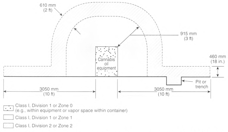
For sources of gas or vapor from a flammable material, the location shall be classified in accordance with the following and as shown in Figure 512.3(B)(2):
- The space within the booth shall be classified as Class I, Division 2 or Zone 2, whichever is applicable.
- The space outside any opening shall be unclassified.
- The interior of fresh air supply ducts and fresh air supply plenums shall be unclassified.
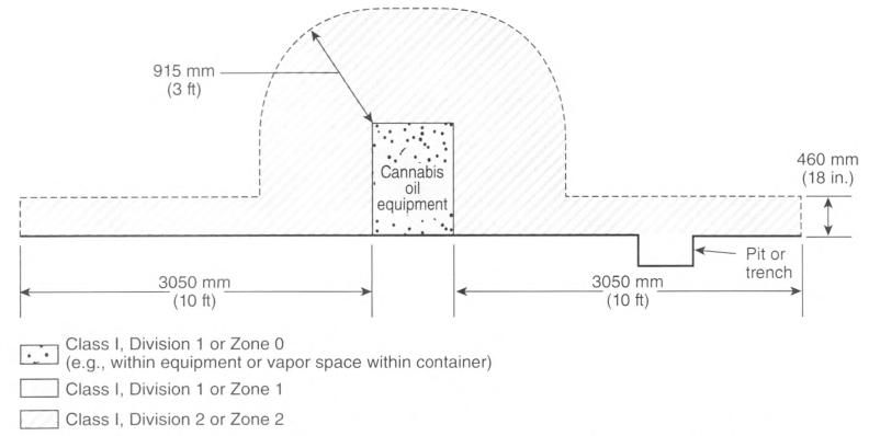
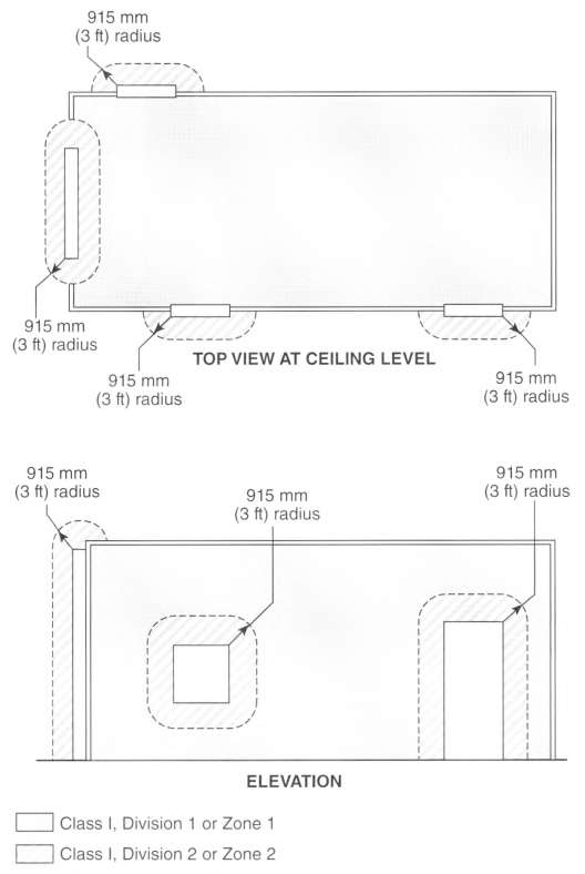
FIGURE 512.3(B)(1) Area Classification for Booths Where Flammable Gases or Vapors Are Released..
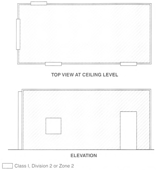
FIGURE 512.3(B)(2) Area Classification for Booths Where Flammable Gases or Vapors Are Not Released Except During Disconnection or Opening.
512.10 Wiring Installation and Operation.
All wiring installed or operated within any of the hazardous (classified) locations defined in 512.3 shall comply with the requirements of Part II of Article 501 or 505.15, as applicable, for the division or zone location in which it is installed.
512.20 Equipment and Systems.
Installation of cannabis oil equipment and systems shall be in a distinct room or area located at commercial or industrial facilities. Where all electrical equipment within cannabis oil booths is listed for Class I, Division 1 or Zone 1 locations, gas detection shall not be required to be provided within the booth. Where gas detection in accordance with 500.7(K) is provided within booths listed for Class I, Division 2 or Zone 2 locations, electrical equipment shall be permitted.
(A) Cannabis Oil Preparatory Equipment.
Equipment that is used to prepare the plant material for subsequent extraction of the plant oil (e.g., trimming, deseeding, drying/curing) shall be listed for the location.
(B) Cannabis Oil Extraction Equipment.
Equipment that uses flammable materials (solvents) in the process of extracting the plant oil from the plant material shall be listed for the location.
Informational Note: Extraction equipment can use flammable materials as solvents to extract the plant oil from the plant material by saturating the plant material in a vented container, sealed container, or pressure vessel. Typical flammable materials used in the extraction process include butane, ethanol, hexane, pentane, propane, and LPG.
(C) Cannabis Oil Booths.
Enclosed areas used to house cannabis oil equipment and systems shall be listed for the location.
Informational Note: Cannabis oil booths can be designed to house a single piece or multiple pieces of cannabis oil equipment. Booths range in size and can be large enough to permit entrance of personnel to perform the processing tasks.
(D) Cannabis Oil Post-Processing Equipment.
Equipment that is used in the final processing stages of the extracted plant oil (e.g., vacuum ovens, rotary evaporators, solvent recovery pumps) shall be listed for the location.
(E) Cannabis Oil Systems.
512.30 Equipment Installed Above Hazardous (Classified) Locations.
Equipment that could produce arcs, sparks, or hot metal particles, such as lamps and lampholders for fixed lighting, cutouts, switches, receptacles, motors, or other equipment having make-and-break or sliding contacts, where installed above a classified location other than cannabis oil booths, shall be of the totally enclosed type or be constructed to prevent the escape of sparks or hot metal particles.
512.32 Marking.
Cannabis oil preparatory equipment, extraction equipment, booths, and post-processing equipment shall be listed and marked to show the hazardous (classified) location for which it is permitted to be installed.
Article 513
Aircraft Hangars
513.1 Scope.
This article shall apply to buildings or structures in any part of which aircraft containing Class I (flammable) liquids or Class II (combustible) liquids whose temperatures are above their flash points are housed or stored and in which aircraft might undergo service, repairs, or alterations. It shall not apply to locations used exclusively for aircraft that have never contained fuel or unfueled aircraft.
Informational Note No. 1: See NFPA 409, Standard on Aircraft Hangars, for definitions of aircraft hangar and unfueled aircraft.
Informational Note No. 2: See NFPA 30, Flammable and Combustible Liquids Code, for information on fuel classification.
513.2 Other Articles.
In addition to the requirements of this article, aircraft hangars shall comply with Table 513.2, as applicable, except as modified by this article.
513.3 Classification of Locations.
Where the term "Class I" is used with respect to Zone classifications within this article of the Code, it shall apply to Zone 0, Zone 1, and Zone 2 designations.
Informational Note: The term "Class I" was originally included as a prefix to Zone 0, Zone 1, and Zone 2 locations and references as an identifier for flammable gases, vapors, or liquids to differentiate from Class II and Class III locations. Zone 0, Zone 1, and Zone 2 only apply to flammable gases, vapors, or liquids so the "Class I" prefix is redundant and has been deleted, except for text that is extracted from other documents or to remain consistent throughout this article.
(C) Vicinity of Aircraft.
(1) Aircraft Maintenance and Storage Hangars.
The area within 1.5 m (5 ft) horizontally from aircraft power plants or aircraft fuel tanks shall be classified as a Class I, Division 2 or Zone 2 location that shall extend upward from the floor to a level 1.5 m (5 ft) above the upper surface of wings and engine enclosures.
(2) Aircraft Painting Hangars.
The area within 3 m (10 ft) horizontally from aircraft surfaces from the floor to 3 m (10 ft) above the aircraft shall be classified as Class I, Division 1 or Zone 1. The area horizontally from aircraft surfaces between 3.0 m (10 ft) and 9.0 m (30 ft) from the floor to 9.0 m (30 ft) above the aircraft surface shall be classified as Class I, Division 2 or Zone 2.
Informational Note: See NFPA 33, Standard for Spray Application Using Flammable or Combustible Materials, for information on ventilation and grounding for static protection in spray painting areas.
(D) Areas Suitably Separated and Ventilated.
Adjacent areas in which flammable liquids or vapors are not likely to be released, such as stock rooms, electrical control rooms, and other similar locations, shall be unclassified where mechanically ventilated at a rate of four or more air changes per hour, designed with positive air pressure, or effectively separated from the hangar itself by walls or partitions.
513.4 Wiring and Equipment in Class I Locations.
(A) General.
All wiring and equipment that is installed or operated within any of the hazardous (classified) locations defined in 513.3 shall comply with the applicable requirements of the hazardous (classified) locations.
Attachment plugs and receptacles shall be identified for the location or shall be designed so they cannot be energized while the connections are being made or broken.
(B) Stanchions, Rostrums, and Docks.
Electrical wiring, outlets, and equipment (including lamps) on or attached to stanchions, rostrums, or docks that are located in a hazardous (classified) location as defined in 513.3(C) shall comply with the applicable requirements of Parts II and III of Article 501 or 505.17 through 505.30. as applicable.
513.7 Wiring and Equipment Not Installed in Class I Locations.
(A) Fixed Wiring.
(B) Pendants.
For pendants, flexible cord suitable for the type of service and identified for hard usage or extra-hard usage shall be used. Each such cord shall include a separate equipment grounding conductor.
(C) Arcing Equipment.
In locations above those described in 513.3, equipment that is less than 3.0 m (10 ft) above wings and engine enclosures of aircraft and that may produce arcs, sparks, or particles of hot metal, such as lamps and lampholders for fixed lighting, cutouts, switches, receptacles, charging panels, generators, motors, or other equipment having make-and-break or sliding contacts, shall be of the totally enclosed type or constructed so as to prevent the escape of sparks or hot metal particles.
(D) Lampholders.
Lampholders of metal-shell, fiber-lined types shall not be used for fixed incandescent lighting.
(E) Stanchions, Rostrums, or Docks.
Where stanchions, rostrums, or docks are not located or likely to be located in a Class I location, as defined in 513.3(C), wiring and equipment shall comply with 513.7, except that such wiring and equipment not more than 457 mm (18 in.) above the floor in any position shall comply with 513.4(B). Receptacles and attachment plugs shall be of a locking type that will not readily disconnect.
(F) Mobile Stanchions.
Mobile stanchions with electrical equipment complying with 513.7(E) shall carry at least one permanently affixed warning sign with the following words or equivalent:
WARNING
KEEP 5 FT CLEAR OF AIRCRAFT ENGINES AND FUEL
TANK AREAS.
or
WARNING
KEEP 1.5 METERS CLEAR OF AIRCRAFT ENGINES AND FUEL
TANK AREAS
KEEP 1.5 METERS CLEAR OF AIRCRAFT ENGINES AND FUEL
TANK AREAS
513.8 Underground Wiring.
(A) Wiring and Equipment Embedded, Under Slab, or Underground.
All wiring installed in or under the hangar floor shall comply with the requirements for Class I, Division 1 locations. Where such wiring is located in vaults, pits, or ducts, adequate drainage shall be provided.
513.10 Special Equipment.
(A) Aircraft Electrical Systems.
(1) De-Energizing Aircraft Electrical Systems.
Aircraft electrical systems shall be de-energized when the aircraft is stored in a hangar and, whenever possible, while the aircraft is undergoing maintenance.
(2) Aircraft Batteries.
Aircraft batteries shall not be charged where installed in an aircraft located inside or partially inside a hangar.
(B) Aircraft Battery Charging and Equipment.
Battery chargers and their control equipment shall not be located or operated within any of the Class I locations defined in 513.3 and shall be located in a separate building or in an area defined in 513.3(D). Mobile chargers shall carry at least one permanently affixed warning sign with the following words or equivalent:
(C) External Power Sources for Energizing Aircraft.
(2) Marking for Mobile Units.
Mobile energizers shall carry at least one permanently affixed warning sign with the following words or equivalent:
WARNING
KEEP 5 FT CLEAR OF AIRCRAFT ENGINES AND FUEL
TANK AREAS.
or
WARNING
KEEP 1.5 METERS CLEAR OF AIRCRAFT ENGINES AND FUEL
TANK AREAS
KEEP 1.5 METERS CLEAR OF AIRCRAFT ENGINES AND FUEL
TANK AREAS
(3) Cords.
Flexible cords for aircraft energizers and ground support equipment shall be identified for the type of service and extra-hard usage and shall include an equipment grounding conductor.
(D) Mobile Servicing Equipment With Electrical Components.
(1) General.
Mobile servicing equipment (such as vacuum cleaners, air compressors, air movers) having electrical wiring and equipment not suitable for Class I, Division 2 or Zone 2 locations shall be so designed and mounted that all such fixed wiring and equipment will be at least 450 mm (18 in.) above the floor. Such mobile equipment shall not be operated within the Class I location defined in 513.3(C) and shall carry at least one permanently affixed warning sign with the following words or equivalent:
(2) Cords and Connectors.
Flexible cords for mobile equipment shall be suitable for the type of service and identified for extra-hard usage and shall include an equipment grounding conductor. Attachment plugs and receptacles shall be identified for the location in which they are installed and shall provide for connection of the equipment grounding conductor.
(3) Restricted Use.
Equipment that is not identified as suitable for Class I, Division 2 locations shall not be operated in locations where maintenance operations likely to release flammable liquids or vapors are in progress.
(E) Portable Equipment.
(1) Portable Lighting Equipment.
Portable lighting equipment that is used within a hangar shall be identified for the location in which they are used. For portable luminaires, flexible cord suitable for the type of service and identified for extra-hard usage shall be used. Each such cord shall include a separate equipment grounding conductor.
(2) Portable Utilization Equipment.
Portable utilization equipment that is or may be used within a hangar shall be of a type suitable for use in Class I, Division 2 or Zone 2 locations. For portable utilization equipment, flexible cord suitable for the type of service and approved for extra-hard usage shall be used. Each such cord shall include a separate equipment grounding conductor.
513.12 Ground-Fault Circuit-Interrupter Protection for Personnel.
Ground-fault circuit-interrupter protection for personnel shall be provided as required in 210.8(B).
513.16 Grounding and Bonding Requirements.
(A) General Grounding Requirements.
All metal raceways, the metal armor or metallic sheath on cables, and all non—current-carrying metal parts of fixed or portable electrical equipment, regardless of voltage, shall be grounded. Grounding in Class I locations shall comply with 501.30 for Class I, Division 1 and 2 locations and 505.30 for Zone 0, 1, and 2 locations.
(B) Supplying Circuits With Grounded and Equipment Grounding Conductors in Class I Locations.
(1) Circuits Supplying Portable Equipment or Pendants.
Where a circuit supplies portables or pendants and includes a grounded conductor, receptacles, attachment plugs, connectors, and similar devices shall be of the grounding type, and the grounded conductor of the flexible cord shall be connected to the screw shell of any lampholder or to the grounded terminal of any utilization equipment supplied.
(2) Approved Means.
Approved means shall be provided for maintaining continuity of the equipment grounding conductor between the fixed wiring system and the non—current-carrying metal portions of pendant luminaires, portable luminaires, and portable utilization equipment.
Article 514
Motor Fuel Dispensing Facilities
514.1 Scope.
This article shall apply to motor fuel dispensing facilities, marine/motor fuel dispensing facilities, motor fuel dispensing facilities located inside buildings, and fleet vehicle motor fuel dispensing facilities.
Informational Note: See NFPA 30A-2021, Code for Motor Fuel Dispensing Facilities and Repair Garages, for information regarding safeguards for motor fuel dispensing facilities and for extracted text that is followed by a reference in brackets. Only editorial changes were made to the extracted text to make it consistent with this Code.
514.2 Other Articles.
In addition to the requirements of this article, motor fuel dispensing facilities shall comply with Table 514.2, as applicable, except as modified by this article.
514.3 Classification of Locations.
Where the term "Class I" is used with respect to Zone classifications within this article of the Code, it shall apply to Zone 0, Zone 1, and Zone 2 designations.
Informational Note: The term "Class I" was originally included as a prefix to Zone 0, Zone 1, and Zone 2 locations and references as an identifier for flammable gases, vapors, or liquids to differentiate from Class II and Class III locations. Zone 0, Zone 1, and Zone 2 only apply to flammable gases, vapors, or liquids so the "Class I" prefix is redundant and has been deleted, except for text that is extracted from other documents or to remain consistent throughout this article.
[See Figure 514.3.]
(A) Unclassified Locations.
Where the authority having jurisdiction can satisfactorily determine that flammable liquids having a flash point below 38°C (100°F), such as gasoline, will not be handled, such location shall not be required to be classified.
(B) Classified Locations.
[See Figure 514.3(B).]
(1) Class I Locations.
Table 514.3(B)(1) shall be applied where Class I liquids are stored, handled, or dispensed and shall be used to delineate and classify motor fuel dispensing facilities and commercial garages as defined in Article 100. Table 515.3 shall be used for the purpose of delineating and classifying aboveground tanks. A Class I location shall not extend beyond an unpierced wall, roof, or other solid partition. [30A:8.1, 8.2, 8.3]
(2) Compressed Natural Gas, Liquefied Natural Gas, and Liquefied Petroleum Gas Areas.
Table 514.3(B)(2) shall be used to delineate and classify areas where CNG, LNG, compressed or liquefied hydrogen, LP-Gas, or combinations of these, are dispensed as motor vehicle fuels along with Class I or Class II liquids that are also dispensed as motor vehicle fuels. [30A:12.1]
Where CNG or LNG dispensers are installed beneath a canopy or enclosure, either the canopy or enclosure shall be designed to prevent accumulation or entrapment of ignitible vapors or all electrical equipment installed beneath the canopy or enclosure shall be suitable for Class I, Division 2 hazardous (classified) locations. [30A:12.4].
Dispensing devices for LP-Gas shall be located as follows:
- At least 3 m (10 ft) from any dispensing device for Class I liquids
-
At least 1.5 m (5 ft) from any dispensing device for Class I liquids where the following conditions exist:
- The LP-Gas deliver nozzle and filler valve release no more than 4 cm3 (0.1 oz) of liquid upon disconnection.
- The fixed maximum liquid level gauge remains closed during the entire refueling process.
Informational Note No. 1: See NFPA 58, Liquefied Petroleum Gas Code, for requirements on dispensing devices for LP-Gas.
Informational Note No. 2: See NFPA 58, Liquefied Petroleum Gas Code, and NFPA 59, Utility LP-Gas Plant Code, for information on classified areas pertaining to LP-Gas systems other than residential or commercial.
(3) Fuel Storage.
- Aboveground tanks storing CNG, LNG, or LP-Gas shall be separated from each other by at least 6 m (20 ft) and from dispensing devices that dispense liquid or gaseous motor vehicle fuels by at least 6 m (20 ft). [30A:12.3.3]Exception No. 1: The required separation shall not apply to tanks or dispensers storing or handling fuels of the same chemical composition.Exception No. 2: The required separation shall not apply when both the gaseous fuel storage and dispensing equipment are at least 15 m (50 ft) from any other aboveground motor fuel storage or dispensing equipment.Informational Note: See NFPA 52, Vehicular Natural Gas Fuel Systems Code, or NFPA 58, Liquefied Petroleum Gas Code, for additional information.
- Dispenser Installations Beneath Canopies. Where CNG or LNG dispensers are installed beneath a canopy or enclosure, either the canopy or enclosure shall be designed to prevent accumulation or entrapment of ignitible vapors or all electrical equipment installed beneath the canopy or enclosure shall be suitable for Class I, Division 2 hazardous (classified) locations. [30A:12.4]
Table 514.3(B)(2) shall be used to delineate and classify areas for the purpose of installation of electrical wiring and electrical utilization equipment.
Aboveground tanks storing CNG or LNG shall be separated from any adjacent property line that is or can be built upon, any public way, and the nearest important building on the same property. [30A:12.3.1].
Informational Note: See NFPA 52, Vehicular Natural Gas Fuel Systems Code, Section 8.4, for the relevant distances for CNG and LNG.
Aboveground tanks storing hydrogen shall be separated from any adjacent property line that is or can be built upon, any public way, and the nearest important building on the same property. [30A:12.3.2].
Informational Note: See NFPA 2, Hydrogen Technologies Code, for the relevant distances for hydrogen.
Aboveground tanks storing LP-Gas shall be separated from any adjacent property line that is or can be built upon, any public way, and the nearest important building on the same property. [30A:12.3.3].
Informational Note: See NFPA 58, Liquefied Petroleum Gas Code, Section 6.3, for the relevant distances for LP-Gas.
Specific Requirements for LP-Gas Dispensing Devices. [30A:12.5] Dispensing devices for LP-Gas shall be located as follows:.
- At least 3 m (10 ft) from any dispensing device for Class I liquids
- At least 1.5 m (5 ft) from any dispensing device for Class I liquids where the following conditions exist:
- The LP-Gas deliver nozzle and filler valve release no more than 4 cm3 (0.1 oz) of liquid upon disconnection.
- The fixed maximum liquid level gauge remains closed during the entire refueling process. [30A:12.5.2]
(C) Motor Fuel Dispensing Stations in Boatyards and Marinas.
Informational Note: See NFPA 303, Fire Protection Standard for Marinas and Boatyards, and NFPA 30A, Code for Motor Fuel Dispensing Facilities and Repair Garages, for additional information.
(2) Classification of Class I, Division 1 and 2 Areas.
The criteria provided in 514.3(C)(2)(a) and (C)(2)(b) shall be used for the purposes of applying Table 514.3(B)(1) and Table 514.3(B)(2) to motor fuel dispensing equipment on floating or fixed piers, wharfs, or docks. 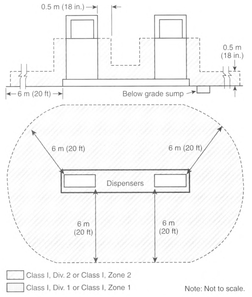
- Closed Construction. Where the construction of floating docks, piers, or wharfs is closed so that there is no space between the bottom of the dock, pier, or wharf and the water, as in the case of concrete-enclosed expanded foam or similar construction, and the construction includes integral service boxes with supply chases, the following shall apply:
- The space above the surface of the floating dock, pier, or wharf shall be a Class I, Division 2 location with distances in accordance with Table 514.3(B)(1) for dispenser and outdoor locations.
- Spaces below the surface of the floating dock, pier, or wharf that have areas or enclosures, such as tubs, voids, pits, vaults, boxes, depressions, fuel piping chases, or similar spaces, where flammable liquid or vapor can accumulate shall be a Class I, Division 1 location.Exception No. 1: Dock, pier, or wharf sections that do not support fuel dispensers and abut, but are located 6.0 m (20 ft) or more from, dock sections that support a fuel dispenser(s) shall be permitted to be Class I, Division 2 locations where documented air space is provided between dock sections to allow flammable liquids or vapors to dissipate without traveling to such dock sections. The documentation shall comply with the requirements of 500.4.Exception No. 2: Dock, pier, or wharf sections that do not support fuel dispensers and do not directly abut sections that support fuel dispensers shall be permitted to be unclassified where documented air space is provided and where flammable liquids or vapors cannot travel to such dock sections. The documentation shall comply with the requirements of 500.4.
- Open Construction. Where the construction of piers, wharfs, or docks is open, as in the case of decks built on stringers supported by pilings, floats, pontoons, or similar construction, the following shall apply:
- The area 450 mm (18 in.) above the surface of the dock, pier, or wharf and extending 6.0 m (20 ft) horizontally in all directions from the outside edge of the dispenser and down to the water level shall be a Class I, Division 2 location.
- Enclosures such as tubs, voids, pits, vaults, boxes, depressions, piping chases, or similar spaces where flammable liquids or vapors can accumulate within 6.0 m (20 ft) of the dispenser shall be a Class I, Division 1 location.
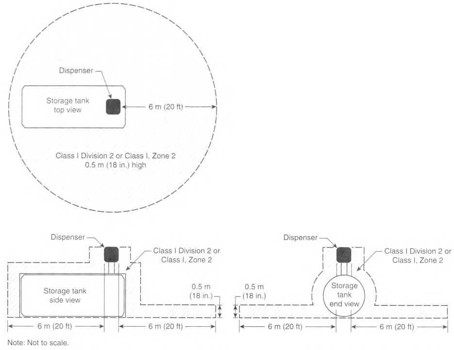
Table 514.3(B)(1) Class I Locations - Motor Fuel Dispensing Facilities.
| Location | Division (Group D) | Zone (Group IIA) | Extent of Classified Location1 |
|---|---|---|---|
| Dispensing Device (except Overhead Type)2, 3 | |||
| Under dispenser containment | 1 | 1 | Entire space within and under dispenser pit or containment |
| Dispenser | 2 | 2 | Within 450 mm (18 in.) of dispenser enclosure or that portion of dispenser enclosure containing liquid-handling components, extending horizontally in all directions and down to grade level |
| Outdoor | 2 | 2 | Up to 450 mm (18 in.) above grade level, extending 6 m (20 ft) horizontally in all directions from dispenser enclosure |
| Indoor | |||
| - with mechanical ventilation | 2 | 2 | Up to 450 mm (18 in.) above floor level, extending 6 m (20 ft) horizontally in all directions from dispenser enclosure |
| - with gravity ventilation | 2 | 2 | Up to 450 mm (18 in.) above floor level, extending 7.5 m (25 ft) horizontally in all directions from dispenser enclosure |
| Dispensing Device - Overhead Type4 | 1 | 1 | Space within dispenser enclosure and all electrical equipment integral with dispensing hose or nozzle |
| 2 | 2 | Within 450 mm (18 in.) of dispenser enclosure, extending horizontally in all directions and down to grade level | |
| 2 | 2 | Up to 450 mm (18 in.) above grade level, extending 6 m (20 ft) horizontally in all directions from a point vertically below edge of dispenser enclosure | |
| Remote Pump - | |||
| Outdoor | 1 | 1 | Entire space within any pit or box below grade level, any part of which is within 3 m (10 ft) horizontally from any edge of pump |
| 2 | 2 | Within 900 mm (3 ft) of any edge of pump, extending horizontally in all directions | |
| 2 | 2 | Up to 450 mm (18 in.) above grade level, extending 3 m (10 ft) horizontally in all directions from any edge of pump | |
| Indoor | 1 | 1 | Entire space within any pit |
| 2 | 2 | Within 1.5 m (5 ft) of any edge of pump, extending in all directions | |
| 9 | 2 | Up to 900 mm (3 ft) above floor level, extending 7.5 m (25 ft) horizontally in all directions from any edge of pump | |
| Sales, Storage, Rest Rooms including structures (such as the attendant's kiosk) on or adjacent to dispensers | unclassified | unclassified | Except as noted below |
| 1 | 1 | Entire volume, if there is any opening to room within the extent of a Division 1 or Zone 1 location | |
| 2 | 2 | Entire volume, if there is any opening to room within the extent of a Division 2 or Zone 2 location | |
| Tank, Aboveground | |||
| Inside tank | 1 | 0 | Entire inside volume |
| Shell, ends, roof, dike area | 1 | 1 | Entire space within dike, where dike height exceeds distance from tank shell to inside of dike wall for more than 50 percent of tank circumference |
| 2 | 2 | Entire space within dike, where dike height does not exceed distance from tank shell to inside of dike wall for more than 50 percent of tank circumference | |
| Vent | 2 | 2 | Within 3 m (10 ft) of shell, ends, or roof of tank |
| 1 | 1 | Within 1.5 m (5 ft) of open end of vent, extending in all directions | |
| 2 | 2 | Between 1.5 m and 3 m (5 ft and 10 ft) from open end of vent, extending in all directions | |
| Tank, Underground | |||
| Inside tank | 1 | 0 | Entire inside volume |
| Fill Opening | 1 | 1 | Entire space within any pit or box below grade level, any part of which is within a Division 1 or Division 2 classified location or within a Zone 1 or Zone 2 classified location |
| 2 | 2 | Up to 450 mm (18 in.) above grade level, extending 1.5 m (5 ft) horizontally in all directions from any tight-fill connection and extending 3 m (10 ft) horizontally in all directions from any loose-fill connection | |
| Vent | 1 | 1 | Within 1.5 m (5 ft) of open end of vent, extending in all directions |
| 2 | 2 | Between 1.5 m and 3 m (5 ft and 10 ft) from open end of vent, extending in all directions | |
| Vapor Processing System | |||
| Pits | 1 | 1 | Entire space within any pit or box below grade level, any part of which: (1) is within a Division 1 or Division 2 classified location; (2) is within a Zone 1 or Zone 2 classified location: (3) houses any equipment used to transfer or process vapors |
| Equipment in protective enclosures | 2 | 2 | Entire space within enclosure |
| Equipment not within protective enclosure | 2 | 2 | Within 450 mm (18 in.) of equipment containing flammable vapors or liquid, extending horizontally in all directions and down to grade level |
| 2 | 2 | Up to 450 mm (18 in.) above grade level within 3 m (10 ft) horizontally of the vapor processing equipment | |
| - Equipment enclosure | 1 | 1 | Entire space within enclosure, if flammable vapor or liquid is present under normal operating conditions |
| 2 | 2 | Entire space within enclosure, if flammable vapor or liquid is not present under normal operating conditions | |
| - Vacuum assist blower | 2 | 2 | Within 450 mm (18 in.) of blower, extending horizontally in all directions and down to grade level |
| 2 | 2 | Up to 450 mm (18 in.) above grade level, extending 3 m (10 ft) horizontally in all directions | |
| Vault | 1 | 1 | Entire interior space, if Class I liquids are stored within |
1For marine application, grade level means the surface of a pier, extending down to water level.
2Refer to Figure 514.3 and Figure 514.3(B) for an illustration of classified location around dispensing devices.
Table 514.3(B)(2) Electrical Equipment Classified Areas for Dispensing Devices.
| Dispensing Device | Extent of Classified Area | ||
|---|---|---|---|
| Class I, Division 1 | Class I, Division 2 | ||
| Compressed natural gas (CNG) | Entire space within the dispenser enclosure | 1.5 m (5 ft) in all directions from dispenser enclosure | |
| Liquefied natural gas (LNG) | Entire space within the dispenser enclosure | 3 m (10 ft) in all directions from the dispenser enclosure | |
| Liquefied petroleum gas (LP-Gas) | Entire space within the dispenser enclosure; 450 mm (18 in.) from the exterior surface of the dispenser enclosure to an elevation of 1.22 m (4 ft) above the base of the dispenser; the entire pit or open space beneath the dispenser and within 6 m (20 ft) horizontally from any edge of the dispenser when the pit or trench is not mechanically ventilated | Up to 450 mm (18 in.) above ground and within 6 m (20 ft) horizontally from any edge of the dispenser enclosure, including pits or trenches within this area when provided with adequate mechanical ventilation | |
[30A:Table 12.6.2]
514.7 Wiring and Equipment Above Hazardous (Classified) Locations.
Fixed wiring and equipment above hazardous (classified) locations shall be installed in accordance with 514.3 and shall be one or more of the following:
- Rigid metal conduit (RMC) or intermediate metal conduit (IMC) with listed threaded or threadless fittings, or electrical metallic tubing (EMT) with listed fittings.
- Rigid polyvinyl chloride conduit (PVC), reinforced thermosetting resin conduit (RTRC), or electrical nonmetallic tubing (ENT).
- Flexible metal conduit (FMC), liquidtight flexible metal conduit (LFMC), or liquidtight flexible nonmetallic conduit (LFNC), with listed fittings.
- Type MC cable, Type AC cable, Type TC cable, or Type TC-ER cable, including installation in cable trays, with listed fittings. Type TC-ER cable shall include an equipment grounding conductor (EGC) in addition to any drain wire.
- Type MI cable terminated with listed fittings and supported to avoid tensile stress.
- Manufactured wiring systems.
- Type PLTC cable or Type PLTC-ER cable used in Class 2 or Class 3 circuits. Type PLTC-ER cable shall include an equipment grounding conductor (EGC) in addition to any drain wire.
- Type ITC cable or ITC-ER cable in accordance with 335.4 and 335.5 and terminated with listed fittings. Type ITC-ER cable shall include an equipment grounding conductor (EGC) in addition to any drain wire.
- Cellular metal floor raceways or cellular concrete floor raceways only for supplying ceiling outlets or extensions to the area below the floor. Such raceways shall have no connections leading into or through any Class I location above the floor.
514.8 Underground Wiring.
(A) Metal Conduit.
Threaded rigid metal conduit (RMC) or threaded intermediate metal conduit (IMC) with listed threaded fittings shall be permitted. Any portion of electrical wiring that is below the surface of a Class I, Division 1 or Division 2 location [as classified in Table 514.3(B)(1) and Table 514.3(B)(2)] shall be sealed within 3.05 m (10 ft) of the point of emergence above grade. The conduit shall not contain any unions, couplings, boxes, or fittings between the conduit seal and the point of emergence above grade.
(C) Nonmetallic Conduit.
Rigid polyvinyl chloride conduit (PVC), reinforced thermosetting resin conduit (RTRC), or high-density polyethylene conduit (HDPE) shall be permitted where buried under not less than 600 mm (2 ft) of cover. Where PVC conduit, RTRC conduit, or HDPE conduit is used, threaded rigid metal conduit (RMC) or threaded intermediate metal conduit (IMC) shall be used for the last 600 mm (2 ft) of the underground run to emergence or to the point of connection to the aboveground raceway. An equipment grounding conductor (EGC) shall be included to provide electrical continuity of the raceway system and for grounding of noncurrent-carrying metal parts.
514.9 Sealing.
(A) At Dispenser.
A listed seal shall be provided in each conduit run entering or leaving a dispenser or any cavities or enclosures in direct communication therewith. The sealing fitting or listed explosionproof reducer at the seal shall be the first fitting after the conduit emerges from the earth or concrete.
(B) At Boundary.
Additional seals shall be provided in accordance with 501.15. Sections 501.15(A)(4) and (B)(2) shall apply to horizontal as well as to vertical boundaries of the defined Class I locations.
514.11 Circuit Disconnects.
(A) Emergency Electrical Disconnects.
Fuel dispensing systems shall be provided with one or more clearly identified emergency shutoff devices or electrical disconnects. Such devices or disconnects shall be installed in approved locations but not less than 6 m (20 ft) or more than 30 m (100 ft) from the fuel dispensing devices that they serve. Emergency shutoff devices or electrical disconnects shall disconnect power to all dispensing devices; to all remote pumps serving the dispensing devices; to all associated power, control, and signal circuits; and to all other electrical equipment in the hazardous (classified) locations surrounding the fuel dispensing devices. When more than one emergency shutoff device or electrical disconnect is provided, all devices shall be interconnected. Resetting from an emergency shutoff condition shall require manual intervention and the manner of resetting shall be approved by the authority having jurisdiction. [30A:6.7] The emergency shutoff device shall disconnect simultaneously from the source of supply, all conductors of the circuits, including the grounded conductor, if any. Equipment grounding conductors shall remain connected.
Exception: Intrinsically safe systems shall not be required to meet this requirement.
(B) Attended Self-Service Motor Fuel Dispensing Facilities.
At attended motor fuel dispensing facilities, the devices or disconnects shall be readily accessible to the attendant. [30A:6.7.1]
(C) Unattended Self-Service Motor Fuel Dispensing Facilities.
At unattended motor fuel dispensing facilities, the devices or disconnects shall be readily accessible to patrons and at least one additional device or disconnect shall be readily accessible to each group of dispensing devices on an individual island. [30A:6.7.2]
514.13 Provisions for Maintenance and Service of Dispensing Equipment.
Each dispensing device shall be provided with a means to remove all external voltage sources, including power, communications, data, and video circuits and including feedback, during periods of maintenance and service of the dispensing equipment. The location of this means shall be permitted to be other than inside or adjacent to the dispensing device. The means shall be capable of being locked in the open position in accordance with 110.25.
Article 515
Bulk Storage Plants
515.1 Scope.
This article covers a property or portion of a property where flammable liquids are received by tank vessel, pipelines, tank car, or tank vehicle and are stored or blended in bulk for the purpose of distributing such liquids by tank vessel, pipeline, tank car, tank vehicle, portable tank, or container.
Informational Note: See NFPA 30-2021, Flammable and Combustible Liquids Code, for extracted text that is followed by a reference in brackets. Only editorial changes were made to the extracted text to make it consistent with this Code.
515.2 Other Articles.
In addition to the requirements of this article, bulk storage plants shall comply with Table 515.2, as applicable, except as modified by this article.
515.3 Classified Locations.
Where the term "Class I" is used with respect to Zone classifications within this article of the Code, it shall apply to Zone 0, Zone 1, and Zone 2 designations. 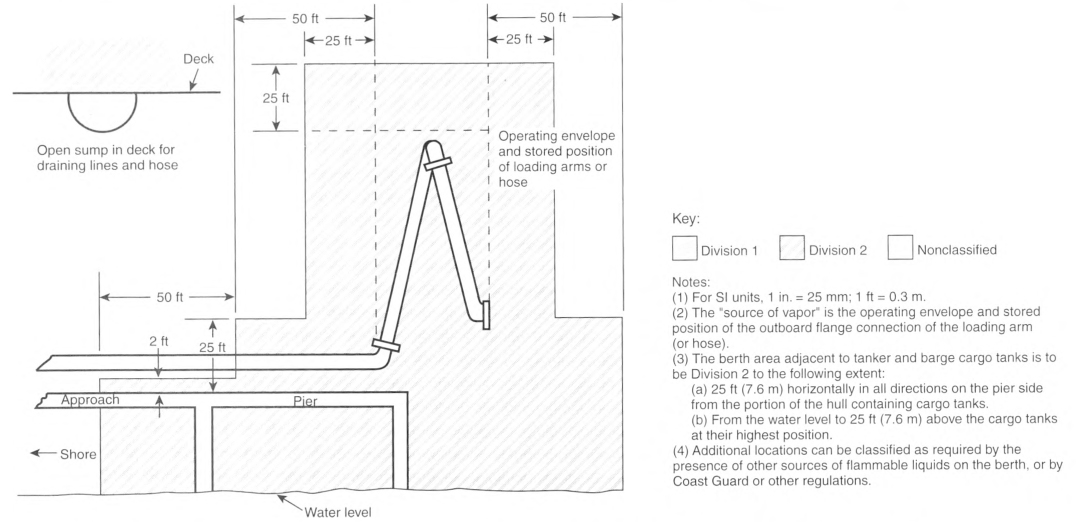
Informational Note No. 1: The term "Class I" was originally included as a prefix to Zone 0, Zone 1, and Zone 2 locations and references as an identifier for flammable gases, vapors, or liquids to differentiate from Class II and Class III locations. Zone 0, Zone 1, and Zone 2 only apply to flammable gases, vapors, or liquids so the "Class I" prefix is redundant and has been deleted, except for text that is extracted from other documents or to remain consistent throughout this article.
Table 515.3 shall be applied where Class I flammable liquids are stored, handled, or dispensed and shall be used to delineate and classify bulk storage plants. The classified location shall not extend beyond a floor, wall, roof, or other solid partition that has no communicating openings.
Where the installation does not meet the requirements found in Table 515.3, the authority having jurisdiction shall have the authority to classify the extent of the classified space.
Informational Note No. 2: See NFPA 30, Flammable and Combustible Liquids Code, Chapter 5, for the area classifications listed in Table 515.3 that are based on the premise that the installation meets all the applicable requirements.
Informational Note No. 3: See 514.3(C) through (E) for gasoline dispensing stations in marinas and boatyards.
Informational Note No. 4: See NFPA 30, Flammable and Combustible Liquids Code, Section 7.3, for additional information.
Table 515.3 Electrical Area Classifications.
| Location | Division | Zone | Extent of Classified Area |
|---|---|---|---|
| Indoor equipment installed where flammable vapor—air mixtures can exist under normal operation (see Informational Note) | 1 | 0 | The entire area associated with such equipment where flammable gases or vapors are present continuously or for long periods of time |
| 1 | 1 | Area within 1.5 m (5 ft) of any edge of such equipment, extending in all directions | |
| 2 | 2 | Area between 1.5 m and 2.5 m (5 ft and 8 ft) of any edge of such equipment, extending in all directions; also, space up to 900 mm (3 ft) above floor or grade level within 1.5 m to 7.5 m (5 ft to 25 ft) horizontally from any edge of such equipment1 | |
| Outdoor equipment installed where flammable vapor—air mixtures can exist under normal operation | 1 | 0 | The entire area associated with such equipment where flammable gases or vapors are present continuously or for long periods of time |
| 1 | 1 | Area within 900 mm (3 ft) of any edge of such equipment, extending in all directions | |
| 2 | 2 | Area between 900 mm (3 ft) and 2.5 m (8 ft) of any edge of such equipment, extending in all directions; also, space up to 900 mm (3 ft) above floor or grade level within 900 mm to 3.0 m (3 ft to 10 ft) horizontally from any edge of such equipment | |
| Tank storage installations inside buildings | 1 | 1 | All equipment located below grade level |
| 2 | 2 | Any equipment located at or above grade level | |
| Tank - aboveground, fixed roof | 1 | 0 | Inside fixed roof tank |
| 1 | 1 | Area inside dike where dike height is greater than the distance from the tank to the dike for more than 50 percent of the tank circumference | |
| 2 | 2 | Within 3.0 m (10 ft) from shell, ends, or roof of tank; also, area inside dike to level of top of dike wall | |
| 1 | 0 | Area inside of vent piping or opening | |
| 1 | 1 | Within 1.5 m (5 ft) of open end of vent, extending in all directions | |
| 2 | 2 | Area between 1.5 m and 3.0 m (5 ft and 10 ft) from open end of vent, extending in all directions | |
| Tank - aboveground, floating roof | |||
| With fixed outer roof | 1 | 0 | Area between the floating and fixed roof sections and within the shell |
| With no fixed outer roof | 1 | 1 | Area above the floating roof and within the shell |
| Tank vault - interior | 1 | 1 | Entire interior volume, if Class I liquids are stored within |
| Underground tank fill opening | 1 | 1 | Any pit, box, or space below grade level, if any part is within a Division 1 or 2, or Zone 1 or 2 classified location |
| 2 | 2 | Up to 450 mm (18 in.) above grade level within a horizontal radius of 3.0 m (10 ft) from a loose fill connection, and within a horizontal radius of 1.5 m (5 ft) from a tight fill connection | |
| Vent - discharging upward | 1 | 0 | Area inside of vent piping or opening |
| 1 | 1 | Within 900 mm (3 ft) of open end of vent, extending in all directions | |
| 2 | 2 | Area between 900 mm and 1.5 m (3 ft and 5 ft) of open end of vent, extending in all directions | |
| Drum and container filling - outdoors or indoors | 1 | 0 | Area inside the drum or container |
| 1 | 1 | Within 900 mm (3 ft) of vent and fill openings, extending in all directions | |
| 2 | 2 | Area between 900 mm and 1.5 m (3 ft and 5 ft) from vent or fill opening, extending in all directions; also, up to 450 mm (18 in.) above floor or grade level within a horizontal radius of 3.0 m (10 ft) from vent or fill opening | |
| Pumps, bleeders, withdrawal fittings | |||
| Indoor | 2 | 2 | Within 1.5 m (5 ft) of any edge of such devices, extending in all directions; also, up to 900 mm (3 ft) above floor or grade level within 7.5 m (25 ft) horizontally from any edge of such devices |
| Outdoor | 2 | 2 | Within 900 mm (3 ft) of any edge of such devices, extending in all directions. Also, up to 450 mm (18 in.) above grade level within 3.0 m (10 ft) horizontally from any edge of such devices |
| Pits and sumps | |||
| Without mechanical ventilation | 1 | 1 | Entire area within a pit or sump if any part is within a Division 1 or 2 or Zone 1 or 2 classified location |
| With adequate mechanical ventilation | 2 | 2 | Entire area within a pit or sump if any part is within a Division 1 or 2 or Zone 1 or 2 classified location |
| Containing valves, fittings, or piping, and not within a Division 1 or 2 or Zone 1 or 2 classified location | 2 | 2 | Entire pit or sump |
| Drainage ditches, separators, impounding basins | |||
| Outdoor | 2 | 2 | Area up to 450 mm (18 in.) above ditch, separator, or basin; also, area up to 450 mm (18 in.) above grade within 4.5 m (15 ft) horizontally from any edge |
| Indoor | Same as pits and sumps | ||
| Tank vehicle and tank car2 | |||
| Loading through open dome | 1 | 0 | Area inside of the tank |
| 1 | 1 | Within 900 mm (3 ft) of edge of dome, extending in all directions | |
| 2 | 2 | Area between 900 mm and 4.5 m (3 ft and 15 ft) from edge of dome, extending in all directions | |
| Loading through bottom connections with atmospheric venting | 1 | 0 | Area inside of the tank |
| 1 | 1 | Within 900 mm (3 ft) of point of venting to atmosphere, extending in all directions | |
| 2 | 2 | Area between 900 mm and 4.5 m (3 ft and 15 ft) from point of venting to atmosphere, extending in all directions; also, up to 450 mm (18 in.) above grade within a horizontal radius of 3.0 m (10 ft) from point of loading connection | |
| Loading through closed dome with atmospheric venting | 1 | 1 | Within 900 mm (3 ft) of open end of vent, extending in all directions |
| 2 | 2 | Area between 900 mm and 4.5 m (3 ft and 15 ft) from open end of vent, extending in all directions; also, within 900 mm (3 ft) of edge of dome, extending in all directions | |
| Loading through closed dome with vapor control | 2 | 2 | Within 900 mm (3 ft) of point of connection of both fill and vapor lines extending in all directions |
| Bottom loading with vapor control or any bottom unloading | 2 | 2 | Within 900 mm (3 ft) of point of connections, extending in all directions; also up to 450 mm (18 in.) above grade within a horizontal radius of 3.0 m (10 ft) from point of connections |
| Storage and repair garage for tank vehicles | 1 | 1 | All pits or spaces below floor level |
| 2 | 2 | Area up to 450 mm (18 in.) above floor or grade level for entire storage or repair garage | |
| Garages for other than tank vehicles | Unclassified | If there is any opening to these rooms within the extent of an outdoor classified location, the entire room shall be classified the same as the area classification at the point of the opening. | |
| Outdoor drum storage | Unclassified | ||
| Inside rooms or storage lockers used for the storage of Class I liquids | 2 | 2 | Entire room or locker |
| Indoor warehousing where there is no flammable liquid transfer | Unclassified | If there is any opening to these rooms within the extent of an indoor classified location, the classified location shall extend through the opening to the same extent as if the wall, curb, or partition did not exist. | |
| Office and rest rooms | Unclassified | If there is any opening to these rooms within the extent of an indoor classified location, the room shall be classified the same as if the wall, curb, or partition did not exist. | |
| Piers and wharves | See Figure 515.3. | ||
1The release of Class I liquids can generate vapors to the extent that the entire building, and possibly an area surrounding it, should be considered a Class I, Division 2 or Zone 2 location.
2When classifying extent of area, consideration shall be given to the fact that tank cars or tank vehicles can be spotted at varying points. Therefore, the extremities of the loading or unloading positions shall be used. [30:Table 7.3.3]
515.4 Wiring and Equipment Located in Hazardous (Classified) Locations.
All electrical wiring and equipment within the hazardous (classified) locations specified in 515.3 shall comply with the applicable requirements of Table 515.2.
515.7 Wiring and Equipment Above Hazardous (Classified) Locations.
(B) Fixed Equipment.
Fixed equipment that might produce arcs, sparks, or particles of hot metal, such as lamps and lamp-holders for fixed lighting, cutouts, switches, receptacles, motors, or other equipment having make-and-break or sliding contacts, shall be of the totally enclosed type or be constructed to prevent the escape of sparks or hot metal particles.
(C) Portable Luminaires or Other Utilization Equipment.
Portable luminaires or other utilization equipment and their flexible cords shall comply with Part III of Article 501 or 505.17 for the class of location above which they are connected or used.
515.8 Underground Wiring.
(A) Wiring Method.
Underground wiring shall be installed in threaded rigid metal conduit or threaded steel intermediate metal conduit or, where buried under not less than 600 mm (2 ft) of cover, shall be permitted in PVC conduit, RTRC conduit, or a listed cable. Where PVC conduit or RTRC conduit is used, threaded rigid metal conduit or threaded steel intermediate metal conduit shall be used for not less than the last 600 mm (2 ft) of the conduit run to the conduit point of emergence from the underground location or to the point of connection to an aboveground raceway. Where cable is used, it shall be enclosed in threaded rigid metal conduit or threaded steel intermediate metal conduit from the point of lowest buried cable level to the point of connection to the above-ground raceway.
515.10 Special Equipment - Motor Fuel Dispensers.
In addition to the requirements of this article, dispensers for gasoline or other volatile flammable liquids or liquified flammable gases shall comply with the requirements for motor fuel dispensing facilities, as applicable, except as modified by this article.
515.16 Grounding and Bonding.
All metal raceways, the metal armor or metallic sheath on cables, and all non—current-carrying metal parts of fixed or portable electrical equipment, regardless of voltage, shall be grounded and bonded.
Grounding and bonding in Class I locations shall comply with 501.30 for Class I, Division 1 and 2 locations and 505.30 for Zone 0, 1, and 2 locations.
Informational Note: See NFPA 30, Flammable and Combustible Liquids Code, 6.5.4, for information on grounding for static protection.
Article 516
Spray Application, Dipping, Coating, and Printing Processes Using Flammable or Combustible Materials
516.1 Scope.
This article covers the regular or frequent application of flammable liquids, combustible liquids, and combustible powders by spray operations and the application of flammable liquids or combustible liquids at temperatures above their flashpoint by spraying, dipping, coating, printing, or other means.
Informational Note No. 1: See NFPA 33-2021, Standard for Spray Application Using Flammable or Combustible Materials, or NFPA 34-2021, Standard for Dipping, Coating, and Printing Processes Using Flammable or Combustible Liquids, for extracted text that is followed by a reference in brackets. Only editorial changes were made to the extracted text to make it consistent with this Code.
Informational Note No. 2: See NFPA 91, Standard for Exhaust Systems for Air Conveying of Vapors, Gases, Mists, and Particulate Solids, for information regarding ventilation.
516.2 Other Articles.
In addition to the requirements of this article, spray application, dipping, coating, and printing processes using flammable or combustible materials shall comply with Table 516.2, as applicable, except as modified by this article.
Table 516.2 Other Articles.
| Requirement | Division Classified Locations | Zone Classified Locations |
|---|---|---|
| Area classification | 500.5, 500.6 | 505.5, 505.6, 505.7, 506.5, 506.6, 506.7 |
| Equipment | 500.7, 500.8, 501.5, 502.5, 502.6, Part III of 501, Part III of 502 | 505.8, 505.9, 505.20, 505.22, 506.8, 506.9 |
| Wiring | Part II of 501, Part II of 502 | 505.15, 505.16, 505.17, 505.18, 505.19, 505.26, 505.30, 506.15, 506.17, 506.20, 506.30 |
516.3 Class I Locations.
Where the term Class I is used with respect to Zone classifications within this article of the Code, it shall apply to Zone 0, Zone 1, and Zone 2 designations.
Informational Note: The term Class I was originally included as a prefix to Zone 0, Zone 1, and Zone 2 locations and references as an identifier for flammable gases, vapors, or liquids to differentiate from Class II and Class III locations. Zone 0, Zone 1, and Zone 2 only apply to flammable gases, vapors, or liquids so the Class I prefix is redundant and has been deleted, except for text that is extracted from other documents or to remain consistent throughout this article.
516.4 Area Classification.
Area classification for open containers, supply containers, waste containers, spray gun cleaners, and solvent distillation units that contain Class I liquids and are located in ventilated areas shall be in accordance with the following:
- The area within 915 mm (3 ft) in all directions from any such container or equipment and extending to the floor or grade level shall be classified as Class I, Division 1 or Zone 1, whichever is applicable. [33:6.5.5.1(1)]
- The area extending 610 mm (2 ft) beyond the Division 1 or Zone 1 location shall be classified as Class I, Division 2 or Zone 2, whichever is applicable. [33:6.5.5.1(2)]
- The area extending 1525 mm (5 ft) horizontally beyond the area described in 516.4(2) up to a height of 460 mm (18 in.) above the floor or grade level shall be classified as Class I, Division 2 or Zone 2, whichever is applicable. [33:6.5.5.1(3)]
- The area inside any tank or container shall be classified as Class I, Division 1 or Zone 0, whichever is applicable. [33:6.5.5.1(4)]
- Sumps, pits, or belowgrade channels within 3.05 m (10 ft) horizontally of a vapor source shall be classified as Class I, Division 1 or Zone 1. If the sump, pit, or channel extends beyond 3.05 m (10 ft) from the vapor source, it shall be provided with a vapor stop or be classified as Class I, Division 1 or Zone 1 for its entire length.
Electrical wiring and utilization equipment installed in these areas shall be suitable for the location, as shown in Figure 516.4. [33:6.5.5.2].
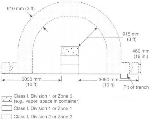
FIGURE 516.4 Electrical Area Classification for Class I Liquid Operations Around Open Containers. Supply Containers, Waste Containers, Spray Gun Cleaners, and Solvent Distillation Units. [33: Figure 6.5.5.2]
516.5 Area Classification.
For spray application processes, the area classification is based on quantities of flammable vapors, combustible mists, residues, dusts, or deposits that are present or might be present in quantities sufficient to produce ignitable or explosive mixtures with air.
(A) Zone Classification of Locations.
(1) Classification of Locations.
The Zone system of electrical area classification shall be applied as follows:
- The inside of closed containers or vessels shall be considered a Class I, Zone 0 location.
- A Class I, Division 1 location shall be permitted to be alternatively classified as a Class I, Zone 1 location.
- A Class I, Division 2 location shall be permitted to be alternatively classified as a Class I, Zone 2 location.
- A Class II, Division 1 location shall be permitted to be alternatively classified as a Zone 21 location.
- A Class II, Division 2 location shall be permitted to be alternatively classified as a Zone 22 location. [33:6.2.2]
(2) Classification Systems.
For the purposes of electrical area classification, the Division system and the Zone system shall not be intermixed for any given source of release. [33:6.2.3]
(3) Equipment.
Open flames, spark-producing equipment or processes, and equipment whose exposed surfaces exceed the autoignition temperature of the material being sprayed shall not be located in a spray area or in any surrounding area that is classified as Division 2, Zone 2, or Zone 22. [33:6.2.5]
Exception: This requirement shall not apply to drying, curing, or fusing apparatus.
Any utilization equipment or apparatus that is capable of producing sparks or particles of hot metal and that is located above or adjacent to either the spray area or the surrounding Division 2, Zone 2, or Zone 22 areas shall be of the totally enclosed type or shall be constructed to prevent the escape of sparks or particles of hot metal. [33:6.2.6]
(C) Class I, Division 1: Class I, Zone 1; Class II, Division 1; or Zone 21 Locations.
The following spaces shall be considered Class I, Division 1; Class I, Zone 1; Class II, Division 1; or Zone 21 locations, as applicable:
- The interior of spray booths and rooms except as specifically provided in 516.5(D).
- The interior of exhaust ducts.
- Any area in the direct path of spray operations.
- Sumps, pits, or below grade channels within 7620 mm (25 ft) horizontally of a vapor source. If the sump, pit, or channel extends beyond 7620 mm (25 ft) from the vapor source, it shall be provided with a vapor stop or it shall be classified as Class I, Division 1 for its entire length. [34:6.4.1]
- All space in all directions outside of but within 900 mm (3 ft) of open containers, supply containers, spray gun cleaners, and solvent distillation units containing flammable liquids.
- For limited finishing workstations, the area inside the curtains or partitions. [See Figure 516.5(D)(5).]
(D) Class I, Division 2; Class I, Zone 2; Class II, Division 2; or Zone 22 Locations.
The spaces listed in 516.5(D)(1) through (D)(5) shall be considered Class I, Division 2; Class I, Zone 2; Class II, Division 2; or Zone 22 as applicable.
(1) Unenclosed Spray Processes.
Electrical wiring and utilization equipment located outside but within 6100 mm (20 ft) horizontally and 3050 mm (10 ft) vertically of an enclosed spray area and not separated from the spray area by partitions extending to the boundaries of the area designated as Division 2, Zone 2 or Zone 22 in Figure 516.5(D)(1) shall be suitable for Class I, Division 2; Class I, Zone 2; Class II, Division 2; or Zone 22 locations, whichever is applicable. [33:6.5.1] [See Figure 516.5(D)(1).]
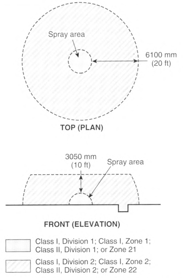
(2) Closed-Top, Open-Face, and Open-Front Spray Booths and Spray Rooms.
If spray application operations are conducted within a closed-top, open-face, or open-front booth or room, as shown in Figure 516.5(D)(2), any electrical wiring or utilization equipment located outside of the booth or room but within 915 mm (3 ft) of any opening shall be suitable for Class I, Division 2; Class I, Zone 2; Class II, Division 2; or Zone 22 locations, whichever is applicable. The Class I, Division 2; Class I, Zone 2; Class II, Division 2; or Zone 22 locations shown in Figure 516.5(D)(2) shall extend from the edges of the open face or open front of the booth or room.
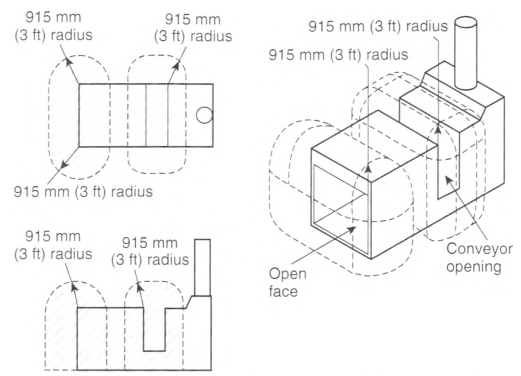
(3) Open-Top Spray Booths.
For spraying operations conducted within an open top spray booth, the space 915 mm (3 ft) vertically above the booth and within 915 mm (3 ft) of other booth openings shall be considered Class I, Division 2; Class I, Zone 2; Class I1. Division 2; or Zone 22 whichever is applicable. [33:6.5.3]
(4) Enclosed Spray Booths and Spray Rooms.
For spray application operations confined to an enclosed spray booth or room, electrical area classification shall be as follows:
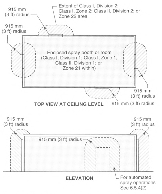
- The area within 915 mm (3 ft) of any opening shall be classified as Class I, Division 2; Class I, Zone 2; Class II. Division 2; or Zone 22 locations, whichever is applicable, as shown in Figure 516.5(D)(4).
- Where automated spray application equipment is used, the area outside the access doors shall be unclassified provided the door interlock prevents the spray application operations when the door is open.
-
Where exhaust air is permitted to be recirculated, both of the following shall apply:
- The interior of any recirculation path from the secondary particulate filters up to and including the air supply plenum shall be classified as Class I, Division 2; Class I, Zone 2; Class II, Division 2; or Zone 22 locations, whichever is applicable.
- The interior of fresh air supply ducts shall be unclassified.
- Where exhaust air is not recirculated, the interior of fresh air supply ducts and fresh air supply plenums shall be unclassified.
[33:6.5.4]
(5) Limited Finishing Workstations.
- For limited finishing workstations, the area inside the 915 mm (3 ft) space horizontally and vertically beyond the volume enclosed by the outside surface of the curtains or partitions shall be classified as Class I, Division 2; Class I, Zone 2; Class II, Division 2; or Zone 22, as shown in Figure 516.5(D)(5).
-
A limited finishing workstation shall be designed and constructed to have all of the following:
- A dedicated make-up air supply
- Curtains or partitions that are noncombustible or limited combustible
- A dedicated mechanical exhaust and filtration system
- The amount of material sprayed in a limited finishing workstation shall not exceed 3.8 L (1 gal) in any 8-hour period. [33:14.3.2]
- Curtains or partitions shall be fully closed during any spray operations. [33:14.3.4]
- The equipment within the limited finishing workstation shall be interlocked such that the spray application equipment cannot be operated unless the exhaust ventilation system is operating and functioning properly and spray application is automatically stopped if the exhaust ventilation system fails.
- Any limited finishing workstation used for spray application operations shall not be used for any operation that is capable of producing sparks or particles of hot metal or for operations that involve open flames or electrical utilization equipment capable of producing sparks or particles of hot metal. [33:14.3.6]
- Where industrial air heaters are used to elevate the air temperature for drying, curing, or fusing operations, a high limit switch shall be provided to automatically shut off the drying apparatus if the air temperature in the limited finishing workstation exceeds the maximum discharge-air temperature allowed by the standard that the heater is listed to or 93°C, (200°F), whichever is less. [33:14.3.7.1]
- A means shall be provided to show that the limited finishing workstation is in the drying or curing mode of operation and that the limited finishing workstation is to be unoccupied. [33:14.3.7.2]
- Any containers of flammable or combustible liquids shall be removed from the limited finishing workstation before the drying apparatus is energized. [33:14.3.7.3]
- Portable spot-drying, curing, or fusion apparatus shall be permitted to be used in a limited finishing workstation, provided that it is not located within the hazardous (classified) location defined in 14.3.5 of NFPA 33 when spray application operations are being conducted. [33:14.3.8]
- Recirculation of exhaust air shall be permitted when the provisions of 516.5(D)(4)(3) are both met. [33:14.3.9]
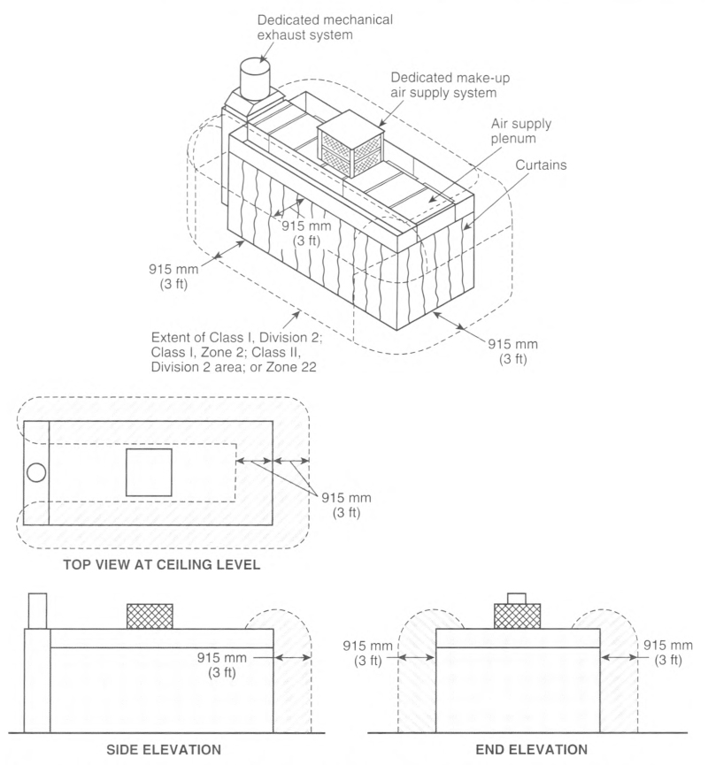
FIGURE 516.5(D)(5) Class I, Division 2; Class I, Zone 2; Class II, Division 2; or Zone 22 Locations Adjacent to a Limited Finishing Workstation. [33:Figure 14.3.6.1]
An approved automatic extinguishing system [33:14.3.1].
Informational Note: See NFPA 701, Standard Methods of Fire Tests for Flame Propagation of Textiles and Films, for information on limited combustible curtains or partitions.
516.6 Wiring and Equipment in Class I Locations.
(B) Wiring and Equipment - Vapors and Residues.
Unless specifically listed for locations containing deposits of dangerous quantities of flammable or combustible vapors, mists, residues, dusts, or deposits (as applicable), there shall be no electrical equipment in any spray area as herein defined whereon deposits of combustible residue could readily accumulate, except wiring in rigid metal conduit, intermediate metal conduit, Type MI cable, or in metal boxes or fittings containing no taps, splices, or terminal connections. [33:6.4.2]
(C) Illumination.
Luminaires shall be permitted to be installed as follows:
- Luminaires, like that shown in Figure 516.6(C)(1), that are attached to the walls or ceiling of a spray area but that are outside any classified area and are separated from the spray area by glass panels shall be suitable for use in unclassified locations. Such fixtures shall be serviced from outside the spray area. [33:6.6.1]
- Luminaires, like that shown in Figure 516.6(C)(1), that are attached to the walls or ceiling of a spray area; that are separated from the spray area by glass panels and that are located within a Class I, Division 2; a Class I, Zone 2; a Class II, Division 2; or a Zone 22 location shall be suitable for such location. Such fixtures shall be serviced from outside the spray area. [33:6.6.2]
- Luminaires, like that shown in Figure 516.6(C)(2), that are an integral part of the walls or ceiling of a spray area shall be permitted to be separated from the spray area by glass panels that are an integral part of the fixture. Such fixtures shall be listed for use in Class I, Division 2; Class I, Zone 2; Class II, Division 2; or Zone 22 locations, whichever is applicable, and also shall be listed for accumulations of deposits of combustible residues. Such fixtures shall be permitted to be serviced from inside the spray area. [33:6.6.3]
- Glass panels used to separate luminaires from the spray area or that are an integral part of the luminaire shall meet the following requirements:
- Panels for luminaires shall be separated from the luminaire to prevent the surface temperature of the panel from exceeding 93°C (200°F). [33:5.5.2]
- The panel frame and method of attachment shall be designed to not fail under fire exposure before the vision panel fails. [33:5.5.3]
Panels for luminaires or for observation shall be of heat-treated glass, laminated glass, wired glass, or hammered-wired glass and shall be sealed to confine vapors, mists, residues, dusts, and deposits to the spray area. [33:5.5.1].
Exception to a.: Listed spray booth assemblies that have vision panels constructed of other materials shall be permitted.
(D) Portable Equipment.
Portable electric luminaires or other utilization equipment shall not be used in a spray area during spray operations.
Exception No. 1: Where portable electric luminaires are required for operations in spaces not readily illuminated by fixed lighting within the spraying area, they shall be of the type identified for Class I, Division 1 or Class I, Zone 1 locations where readily ignitible residues could be present. [33:6.9 Exception].
Exception No. 2: Where portable electric drying apparatus is used in spray booths and the following requirements are met:
(1) The apparatus and its electrical connections are not located within the spray enclosure during spray operations.
(2) Electrical equipment within 450 mm (18 in.) of the floor is identified for Class I, Division 2 or Class I, Zone 2 locations.
(3) All metallic parts of the drying apparatus are electrically bonded and grounded.
(E) Electrostatic Equipment.
Electrostatic spraying or detearing equipment shall be installed and used only as provided in 516.10.
Informational Note: See NFPA 33, Standard for Spray Application Using Flammable or Combustible Materials, for additional information.
(F) Static Electric Discharges.
All persons and all electrically conductive objects, including any metal parts of the process equipment or apparatus, containers of material, exhaust ducts, and piping systems that convey flammable or combustible liquids, shall be electrically grounded. [34:6.8.1] 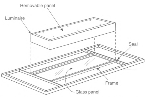
FIGURE 516.6(C)(1) Example of a Luminaire Mounted Outside the Spray Area and Serviced from Outside the Spray Area. [33:Figure 6.6.1.1].
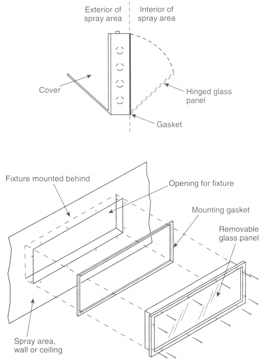
FIGURE 516.6(C)(2) Example of Luminaires That Are Integral Parts of the Spray Area and That Are Serviced from Inside the Spray Area. [33:Figure 6.6.3.1]
516.7 Wiring and Equipment Not Within Hazardous (Classified) Locations.
(A) Wiring.
All fixed wiring above hazardous (classified) locations shall be permitted to be one or more of the following:
- Rigid metal conduit (RMC) or intermediate metal conduit (IMC) with listed threaded or threadless fittings, or electrical metallic tubing (EMT) with listed fittings.
- Rigid polyvinyl chloride conduit (PVC), reinforced thermosetting resin conduit (RTRC), or electrical nonmetallic tubing (ENT).
- Type MC cable, Type TC cable, or Type TC-ER cable, including installation in cable trays, terminated with listed fittings. Type TC-ER cable shall include an equipment grounding conductor (EGC) in addition to any drain wire.
- Type MI cable terminated with listed fittings and installed and supported to avoid tensile stress.
- Type PLTC cable or Type PLTC-ER cable used in Class 2 or Class 3 circuits. Type PLTC-ER cable shall include an equipment grounding conductor (EGC) in addition to any drain wire.
- Type ITC cable or Type ITC-ER cable in accordance with 335.4 and 335.5 and terminated with listed fittings. Type ITC-ER cable shall include an EGC in addition to any drain wire.
- Cellular metal raceways supplying ceiling outlets or as extensions to the area below the floor of a hazardous (classified) location. If cellular metal raceways are used, they shall not have connections leading into or passing through the hazardous (classified) location unless suitable seals are provided.
(B) Equipment.
Equipment that could produce arcs, sparks, or particles of hot metal, such as lamps and lampholders for fixed lighting, cutouts, switches, receptacles, motors, or other equipment having make-and-break or sliding contacts, where installed above a classified location or above a location where freshly finished goods are handled, shall be of the totally enclosed type or be constructed to prevent the escape of sparks or hot metal particles.
516.10 Special Equipment.
(A) Fixed Electrostatic Equipment.
This section shall apply to any equipment using electrostatically charged elements for the atomization, charging, and/or precipitation of hazardous materials for coatings on articles or for other similar purposes in which the charging or atomizing device is attached to a mechanical support or manipulator, including robotic devices. This section shall not apply to devices that are held or manipulated by hand. Where robot or programming procedures involve manual manipulation of the robot arm while spraying with the high voltage on, the requirements of 516.10(B) shall apply. The installation of electrostatic spraying equipment shall comply with the requirements of 516.10(A)(1) through (A)(10). Spray equipment shall be listed. All automatic electrostatic equipment systems shall comply with the requirements of 516.6(B) through (D) and 516.6(F).
(1) Power and Control Equipment.
Transformers, high-voltage supplies, control apparatus, and all other electrical portions of the equipment shall be installed outside of the Class I location or be of a type identified for the location.
Exception: High-voltage grids, electrodes, electrostatic atomizing heads, and their connections shall be permitted within the Class I location.
(2) Electrostatic Equipment.
Electrodes and electrostatic atomizing heads shall be adequately supported in permanent locations and shall be effectively insulated from ground. Electrodes and electrostatic atomizing heads that are permanently attached to their bases, supports, reciprocators, or robots shall be deemed to comply with this section.
(3) High-Voltage Leads.
High-voltage leads shall be properly insulated and protected from mechanical damage or exposure to destructive chemicals. Any exposed element at high voltage shall be effectively and permanently supported on suitable insulators and shall be effectively guarded against accidental contact or grounding.
(4) Support of Goods.
Goods being coated using this process shall be supported on conveyors or hangers. The conveyors or hangers shall be arranged (1) to ensure that the parts being coated are electrically connected to ground with a resistance of 1 megohm or less and (2) to prevent parts from swinging.
(5) Automatic Controls.
Electrostatic apparatus shall be equipped with automatic means that will rapidly de-energize the high-voltage elements under any of the following conditions:
- Stoppage of ventilating fans or failure of ventilating equipment from any cause
- Stoppage of the conveyor carrying goods through the high-voltage field unless stoppage is required by the spray process
- Occurrence of excessive current leakage at any point in the high-voltage system
- De-energizing the primary voltage input to the power supply
(6) Grounding.
All electrically conductive objects in the spray area, except those objects required by the process to be at high voltage, shall be adequately grounded. This requirement shall apply to paint containers, wash cans, guards, hose connectors, brackets, and any other electrically conductive objects or devices in the area.
Informational Note: See NFPA 33, Standard for Spray Application Using Flammable nr Combustible Materials; NFPA 34, Standard for Dipping, Coating, and Printing Processes Using Flammable or Combustible Liquids, and NFPA 77, Recommended Practice on Static Electricity, for information on grounding and bonding for static electricity purposes.
(7) Isolation.
Safeguards such as adequate booths, fencing, railings, interlocks, or other means shall be placed about the equipment or incorporated therein so that they, either by their location, character, or both, ensure that a safe separation of the process is maintained.
(8) Signs.
Signs shall be conspicuously posted to convey the following:
- Designate the process zone as dangerous with regard to lire and accident
- Identify the grounding requirements for all electrically conductive objects in the spray area
- Restrict access to qualified personnel only
(9) Insulators.
All insulators shall be kept clean and dry.
Other Than Nonincendive Equipment.
Spray equipment that cannot be classified as nonincendive shall comply with 516.10(A) (10) (a) and (A) (10) (b).
- Conveyors, hangers, and application equipment shall be arranged so that a minimum separation of at least twice the sparking distance is maintained between the workpiece or material being sprayed and electrodes, electrostatic atomizing heads, or charged conductors. Warnings defining this safe distance shall be posted. [33:11.4.1]
- The equipment shall provide an automatic means of rapidly de-energizing the high-voltage elements in the event the distance between the goods being painted and the electrodes or electrostatic atomizing heads falls below that specified in 516.10(A)(10)(a). [33:11.3.8]
(B) Hand-Spraying Electrostatic Equipment.
This section shall apply to any equipment using electrostatically charged elements for the atomization, charging, or precipitation of flammable and combustible materials for coatings on articles, or for other similar purposes in which the charging or atomizing device is hand-held and manipulated during the spraying operation. Electrostatic hand-spraying equipment and devices used in connection with paint-spraying operations shall be of listed types and shall comply with 516.10(B)(1) through (B)(5).
(1) General.
The high-voltage circuits shall be designed so as not to produce a spark of sufficient intensity to ignite the most readily ignitible of those vapor—air mixtures likely to be encountered or result in appreciable shock hazard upon coming in contact with a grounded object under all normal operating conditions. The electrostatically charged exposed elements of the handgun shall be capable of being energized only by an actuator that also controls the coating material supply.
(2) Power Equipment.
Transformers, power packs, control apparatus, and all other electrical portions of the equipment shall be located outside of the Class I location or be identified for the location.
Exception: The handgun itself and its connections to the power supply shall be permitted within the Class I location.
(3) Handle.
The handle of the spraying gun shall be electrically connected to ground by a conductive material and be constructed so that the operator in normal operating position is in electrical contact with the grounded handle with a resistance of not more than 1 megohm to prevent buildup of a static charge on the operator's body. Signs indicating the necessity for grounding other persons entering the spray area shall be conspicuously posted.
(4) Electrostatic Equipment.
All electrically conductive objects in the spraying area, except those objects required by the process to be at high voltage shall be electrically connected to ground with a resistance of not more than 1 megohm. This requirement shall apply to paint containers, wash cans, and any other electrical conductive objects or devices in the area. The equipment shall carry a prominent, permanently installed warning regarding the necessity for this grounding feature.
Informational Note: See NFPA 33, Standard for Spray Application Using Flammable or Combustible Materials, NFPA 34, Standard for Dipping, Coating, and Printing Processes Using Flammable or Combustible Liquids, and NFPA 77, Recommended Practice on Static Electricity, for information on grounding and bonding for static electricity purposes.
(5) Support of Objects.
Objects being painted shall be maintained in electrical contact with the conveyor or other grounded support. Hooks shall be regularly cleaned to ensure adequate grounding of 1 megohm or less. Areas of contact shall be sharp points or knife edges where possible. Points of support of the object shall be concealed from random spray where feasible, and, where the objects being sprayed are supported from a conveyor, the point of attachment to the conveyor shall be located so as to not collect spray material during normal operation.
(C) Powder Coating.
This section shall apply to processes in which combustible dry powders are applied. The hazards associated with combustible dusts are present in such a process to a degree, depending on the chemical composition of the material, particle size, shape, and distribution.
(1) Electrical Equipment and Sources of Ignition.
Electrical equipment and other sources of ignition shall comply with the requirements of Part III of Article 502 or 506.20, as applicable. Portable electric luminaires and other utilization equipment shall not be used within a Class II location during operation of the finishing processes. Such luminaires or utilization equipment used during cleaning or repairing operations shall be of a type identified for Class II, Division 1 locations and all exposed metal parts shall be connected to an equipment grounding conductor.
Exception: Portable electric luminaires shall be of the type listed for Class II, Division 1 locations where required for operations in spaces not readily illuminated by fixed lighting within the spraying area and where readily ignitible residues might be present.
(4) Electrostatic Fluidized Beds.
Electrostatic fluidized beds and associated equipment shall be of identified types. The high-voltage circuits shall be designed such that any discharge produced when the charging electrodes of the bed are approached or contacted by a grounded object shall not be of sufficient intensity to ignite any powder-air mixture likely to be encountered or to result in an appreciable shock hazard.
- Transformers, power packs, control apparatus, and all other electrical portions of the equipment shall be located outside the powder-coating area or shall otherwise comply with the requirements of 516.10(C)(1).Exception: The charging electrodes and their connections to the power supply shall be permitted within the powder-coating area.
- All electrically conductive objects within the powder-coating area shall be adequately grounded. The powder-coating equipment shall carry a prominent, permanently installed warning regarding the necessity for grounding these objects.Informational Note: See NFPA 33, Standard for Spray Application Using Flammable or Combustible Materials; NFPA 34, Standard for Dipping, Coating, and Printing Processes Using Flammable or Combustible Liquids; and NFPA 77, Recommended Practice on Static Electricity, for information on grounding and bonding for static electricity purposes.
- Objects being coated shall be maintained in electrical contact (less than 1 megohm) with the conveyor or other support in order to ensure proper grounding. Hangers shall be regularly cleaned to ensure effective electrical contact. Areas of electrical contact shall be sharp points or knife edges where possible.
- The electrical equipment and compressed air supplies shall be interlocked with a ventilation system so that the equipment cannot be operated unless the ventilating fans are in operation. [33:Chapter 15]
516.18 Area Classification for Temporary Membrane Enclosures.
Electrical area classification shall be as follows: 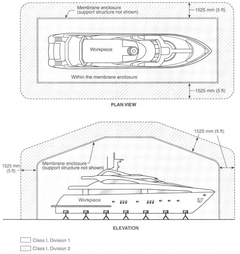
- The area within the membrane enclosure shall be considered a Class I, Division 1 area, as shown in Figure 516.18.
- A 1.5 m (5 ft) zone outside of the membrane enclosure shall be considered Class I, Division 2, as shown in Figure 516.18.
Informational Note No. 1: See NFPA 33, Standard for Spray Application Using Flammable or Combustible Materials, for information on occupancy, ventilation, fire protection, and permitting for spray application operations in membrane enclosures. This document limits spray application operations within both outdoor and indoor temporary membrane enclosures, as well as use and time constraints. The risks to people and property are unique when spray painting within the confined spaces of temporary membrane enclosures.
Informational Note No. 2: See NFPA 33, Standard for Spray Application Using Flammable or Combustible Materials, Section 18.6, for the limits of material used in a vertical plane for membrane enclosures.
Informational Note No. 3: See NFPA 701, Standard Methods of Fire Tests for Flame Propagation of Textiles and Films, Test Method 2, for construction information.
Informational Note No. 4: See NFPA 33, Standard for Spray Application Using Flammable or Combustible Materials, 18.3.2.1.1, for membrane installation beneath sprinklers.
Informational Note No. 5: See NFPA 13, Standard for the Installation of Sprinkler Systems, 8.15.15, for information on the protection of membrane structures.
FIGURE 516.18 Electrical Classifications for Outdoor Membrane Enclosures. [33:Figure 18.6.1.2]
516.23 Electrical and Other Sources of Ignition.
Electrical wiring and utilization equipment used within the classified areas inside and outside of membrane enclosures during spray painting shall be suitable for the location and shall comply with all of the following:
516.29 Classification of Locations.
Classification is based on quantities of flammable vapors, combustible mists, residues, dusts, or deposits that are present or might be present in quantities sufficient to produce ignitable or explosive mixtures with air. Electrical wiring and electrical utilization equipment located adjacent to open processes shall comply with the requirements as follows. Examples of these requirements are illustrated in Figure 516.29(1), Figure 516.29(2), Figure 516.29(3), and Figure 516.29(4). 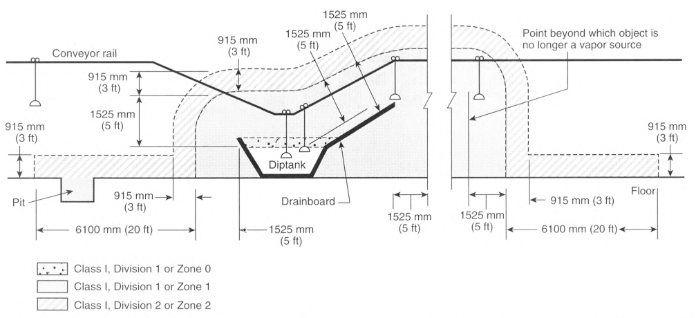
Informational Note: See NFPA 33, Standard for Spray Application Using Flammable or Combustible Materials, Chapter 6, and NFPA 34, Standard for Dipping, Coating, and Printing Processes Using Flammable nr Combustible Liquids, Chapter 6, for additional information.
- Electrical wiring and electrical utilization equipment located in any sump, pit, or below grade channel that is within 7620 mm (25 ft) horizontally of a vapor source, as defined by this standard, shall be suitable for Class I, Division 1 or Class I, Zone 1 locations. If the sump, pit, or channel extends beyond 7620 mm (25 ft) of the vapor source, it shall be provided with a vapor stop, or it shall be classified as Class I, Division 1 or Class I, Zone I for its entire length. [34:6.4.1]
- Electrical wiring and electrical utilization equipment located within 1525 mm (5 ft) of a vapor source shall be suitable for Class I, Division 1 or Class I, Zone 1 locations. The space inside a dip tank, ink fountain, ink reservoir, or ink tank shall be classified as Class I, Division 1 or Class I. Zone 0, whichever is applicable.
- Electrical wiring and electrical utilization equipment located within 915 mm (3 ft) of the Class I, Division 1 or Class I, Zone 1 location shall be suitable for Class I. Division 2 or Class I. Zone 2 locations, whichever is applicable.
- The space 915 mm (3 ft) above the floor and extending 6100 mm (20 ft) horizontally in all directions from the Class I, Division 1 or Class I, Zone 1 location shall be classified as Class I, Division 2 or Class I, Zone 2, and electrical wiring and electrical utilization equipment located within this space shall be suitable for Class I, Division 2 or Class I, Zone 2 locations, whichever is applicable.
- This space shall be permitted to be nonclassified for purposes of electrical installations if the surface area of the vapor source does not exceed 0.5 m2 (5 ft2), the contents of the dip tank, ink fountain, ink reservoir, or ink tank do not exceed 19 L (5 gal), and the vapor concentration during operating and shutdown periods does not exceed 25 percent of the lower flammable limit.
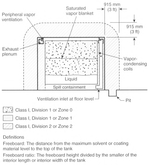
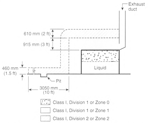
FIGURE 516.29(3) Electrical Area Classification for Open Dipping and Coating Processes with Partial Peripheral Vapor Containment and Ventilation - Vapors NOT Confined to Process Equipment. [34:Figure 6.4(c)].
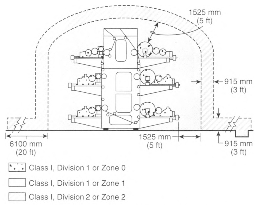
FIGURE 516.29(4) Electrical Area Classification for a Typical Printing Process. [34:Figure 6.4(d)]
516.35 Areas Adjacent to Enclosed Dipping and Coating Processes.
Areas adjacent to enclosed dipping and coating processes are illustrated by Figure 516.35 and shall be classified as follows: 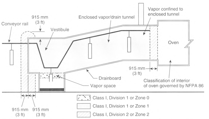
- The interior of any enclosed dipping or coating process or apparatus shall be a Class I, Division 1 or Class I, Zone 1 location, and electrical wiring and electrical utilization equipment located within this space shall be suitable for Class I, Division 1 or Class I, Zone 1 locations, whichever is applicable. The area inside the dip tank shall be classified as Class I, Division 1 or Class I, Zone 0, whichever is applicable.
- The space within 915 mm (3 ft) in all directions from any opening in the enclosure and extending to the floor or grade level shall be classified as Class I, Division 2 or Class I, Zone 2, and electrical wiring and electrical utilization equipment located within this space shall be suitable for Class I, Division 2 locations or Class I, Zone 2 locations, whichever is applicable.
- All other spaces adjacent to an enclosed dipping or coating process or apparatus shall be classified as nonhazardous for purposes of electrical installations.
FIGURE 516.35 Electrical Area Classification Around Enclosed Dipping and Coating Processes. [34:Figure 6.5]
516.36 Equipment and Containers in Ventilated Areas.
Open containers, supply containers, waste containers, and solvent distillation units that contain Class I liquids shall be located in areas ventilated in accordance with 516.4.
516.37 Luminaires.
For printing, coating, and dipping equipment where the process area is enclosed by glass panels that are sealed to confine vapors and mists to the inside of the enclosure, luminaires that are attached to the walls or ceilings of a process enclosure and that are located outside of any classified area shall be permitted to be of general purpose construction. Such luminaires shall be serviced from outside the enclosure.
Luminaires that are attached to the walls or ceilings of a process enclosure, are located within the Class I, Division 2 or Class I, Zone 2 location, and are separated from the process area by glass panels that are sealed to confine vapors and mists shall be suitable for use in that location. Such fixtures shall be serviced from outside the enclosure.
516.38 Wiring and Equipment Not Within Hazardous (Classified) Locations.
(A) Wiring.
Fixed wiring above hazardous (classified) locations shall be permitted to be one or more of the following:
- Rigid metal conduit (RMC) or intermediate metal conduit (IMC) with listed threaded or threadless fittings, or electrical metallic tubing (EMT) or electrical nonmetallic tubing (Type ENT) with listed fittings.
- Rigid polyvinyl chloride conduit (PVC) or reinforced thermosetting resin conduit (RTRC).
- Type MC cable or Type TC cable with listed fittings.
- Type MI cable terminated with listed fittings and installed and supported to avoid tensile stress.
- Cellular metal floor raceways only to supply ceiling outlets or as extensions to the area below the floor of a hazardous (classified) location. If cellular metal raceways are used, they shall not have connections leading into or passing through the hazardous (classified) location unless suitable seals are provided.
(B) Equipment.
Equipment that is capable of producing arcs, sparks, or particles of hot metal, such as lamps and lampholders for fixed lighting, cutouts, switches, receptacles, motors, or other equipment having make-and-break or sliding contacts, where installed above a classified location or above a location where freshly finished goods are handled, shall be of the totally enclosed type or be constructed to prevent the escape of sparks or hot metal particles.
516.40 Static Electric Discharges.
All persons and all electrically conductive objects, including any metal parts of the process equipment or apparatus, containers of material, exhaust ducts, and piping systems that convey flammable or combustible liquids, shall be electrically grounded.
Provision shall be made to dissipate static electric charges from all nonconductive substrates in printing processes.
Informational Note: See NFPA 77, Recommended Practice on Static Electricity, for information on reducing the risk of ignition from electrostatic discharges.
Article 517
Health Care Facilities
517.1 Scope.
This article applies to electrical construction and installation criteria in health care facilities that provide services to human beings.
The requirements of this article shall specify the installation criteria and wiring methods that minimize electrical hazards by the maintenance of adequately low potential differences only between exposed conductive surfaces that are likely to become energized and could be contacted by a patient.
Informational Note No. 1: In a health care facility, it is difficult to prevent the occurrence of a conductive or capacitive path from the patient's body to some grounded object, because that path might be established accidentally or through instrumentation directly connected to the patient. Other electrically conductive surfaces that might make an additional contact with the patient, or instruments that might be connected to the patient, then become possible sources of electric currents that can traverse the patient's body. The hazard is increased as more apparatus is associated with the patient, therefore more intensive precautions are needed. Control of electric shock hazard requires the limitation of electric current that might flow in an electrical circuit involving the patient's body by raising the resistance of the conductive circuit that includes the patient, or by insulating exposed conductive surfaces that might become energized, in addition to reducing the potential difference that can appear between exposed conductive surfaces in the patient care vicinity, or by combinations of these methods. A special problem is presented by the patient with an externalized direct conductive path to the heart muscle. The patient could be electrocuted at current levels so low that additional protection in the design of appliances, insulation of the catheter, and control of medical practice is required.
The requirements in Parts II and III not only apply to single-function buildings but are also intended to be individually applied to their respective forms of occupancy within a multifunction building [e.g., a doctor's examining room located within a limited care facility would be required to meet 517.10(A)].
Informational Note No. 2: For information concerning performance, maintenance, and testing criteria, refer to the appropriate health care facilities documents.
Informational Note No. 3: Text that is followed by a reference in brackets has been extracted from NFPA 99-2021, Health Care Facilities Code, or NFPA 101-2021, Life Safety Code. Only editorial changes were made to the extracted text to make it consistent with this Code.
517.6 Patient Care-Related Electrical Equipment.
The reconditioning requirements of this Code shall not apply to patient care-related electrical equipment.
Informational Note No. 1: Patient care-related electrical equipment is differentiated from electrical equipment as described in 110.21(A)(2).
Informational Note No. 2: If patient care—related electrical equipment is relocated, it is expected to be recommissioned or recertified in accordance with the U.S. Federal Food, Drug, and Cosmetic Act (FDCA).
517.10 Applicability.
(B) Not Covered.
Part II shall not apply to the following:
- Business offices, corridors, waiting rooms, and the like in clinics, medical and dental offices, and outpatient facilities
- Spaces of nursing homes and limited care facilities wired in accordance with Chapters 1 through 4 of this Code where these spaces are used exclusively as patient sleeping rooms, as determined by the health care facility's governing bodyInformational Note No. 1: See 406.12(5) for receptacles located in health care facility business offices, corridors, and waiting rooms that are required to be tamper resistant.Informational Note No. 2: See 210.12(D) for branch circuits supplying outlets and receptacles located in patient sleeping rooms in nursing homes and limited care facilities that are connected to arc-fault circuit-interrupter circuits.
- Areas used exclusively for any of the following purposes:
- Intramuscular injections (immunizations)
- Psychiatry and psychotherapy
- Alternative medicine
- Optometry
- Pharmacy services not contiguous to health care facilities
Informational Note No. 3: See NFPA 101-2021, Life Safety Code.
517.13 Equipment Grounding Conductor for Receptacles and Fixed Electrical Equipment in Patient Care Spaces.
Wiring serving patient care spaces shall comply with the requirements of 517.13 (A) and (B).
Exception: Luminaires more than 2.3 m (71/2 ft) above the floor and switches located outside of the patient care vicinity shall be permitted to be connected to an equipment grounding return path complying with the requirements of 517.13(A) or (B).
(A) Wiring Methods.
All branch circuits serving patient care spaces shall be provided with an effective ground-fault current path by installation in a metal raceway system or a cable having a metallic armor or sheath assembly. The metal raceway system, metallic cable armor, or sheath assembly shall itself qualify as an equipment grounding conductor in accordance with 250.118.
(B) Insulated Equipment Grounding Conductors and Insulated Equipment Bonding Jumpers.
(1) General.
An insulated copper equipment grounding conductor that is clearly identified along its entire length by green insulation and installed with the branch circuit conductors within the wiring method in accordance with 517.13(A) shall be connected to the following:
- Grounding terminals of all receptacles other than isolated ground receptacles
- Metal outlet boxes, metal device boxes, or metal enclosures
- Non-current-carrying conductive surfaces of fixed electrical equipment likely to become energized that are subject to personal contact, operating at over 100 volts
Exception No. 1: For other than isolated ground receptacles, an insulated equipment bonding jumper that directly connects to the equipment grounding conductor shall be permitted to connect the box and receptacle(s) to the equipment grounding conductor. Isolated ground receptacles shall be connected in accordance with 517.16.
Exception No. 2: Metal faceplates shall be connected to an effective ground-fault current path by means of a metal mounting screw(s) securing the faceplate to a metal yoke or strap of a receptacle or to a metal outlet box.
517.14 Panelboard Bonding.
The equipment grounding terminal buses of the normal and essential branch-circuit panelboards serving the same individual patient care vicinity shall be connected together with an insulated continuous copper conductor not smaller than 10 AWG. Where two or more panelboards serving the same individual patient care vicinity are served from separate transfer switches on the essential electrical system, the equipment grounding terminal buses of those panelboards shall be connected together with an insulated continuous copper conductor not smaller than 10 AWG. This conductor shall be permitted to be broken in order to terminate on the equipment grounding terminal bus in each panelboard.
Exception: The insulated continuous copper conductor not smaller than 10 AWG shall be permitted to be terminated on listed connections to aluminum or copper busbars not smaller than 6 mm thick × 50 mm wide (1/4 in. thick × 2 in. wide) and of sufficient length to accommodate the number of terminations necessary for the bonding of the panelboards. The busbar shall be securely fastened and installed in an accessible location.
517.16 Use of Isolated Ground Receptacles.
An isolated ground receptacle, if used, shall not defeat the purposes of the safety features of the grounding systems detailed in 517.13. [99:6.3.2.2.5(A)]
(A) Inside of a Patient Care Vicinity.
An isolated ground receptacle shall not be installed within a patient care vicinity. [99:6.3.2.2.5(B)]
(B) Outside of a Patient Care Vicinity.
Isolated ground receptacle(s) installed in patient care spaces outside of a patient care vicinity(s) shall comply with 517.16(B)(1) and (B)(2).
(1) .
The equipment grounding terminals of isolated ground receptacles installed in branch circuits for patient care spaces shall be connected to an insulated equipment grounding conductor in accordance with 250.146(D) installed in a wiring method described in 517.13(A).
The equipment grounding conductor connected to the equipment grounding terminals of isolated ground receptacles in patient care spaces shall be clearly identified along the equipment grounding conductor's entire length by green insulation with one or more yellow stripes.
(2) .
The insulated equipment grounding conductor required in 517.13(B)(1) shall be clearly identified along its entire length by green insulation, with no yellow stripes, and shall not be connected to the grounding terminals of isolated equipment ground receptacles but shall be connected to the box or enclosure indicated in 517.13(B)(1)(2) and to non—current-carrying conductive surfaces of fixed electrical equipment indicated in 517.13(B)(1)(3).
Informational Note No. 1: This type of installation is typically used where a reduction of electrical noise (electromagnetic interference) is necessary, and parallel grounding paths are to be avoided.
Informational Note No. 2: Care should be taken in specifying a system containing isolated ground receptacles, because the impedance of the effective ground-fault current path is dependent upon the equipment grounding conductor(s) and does not benefit from any conduit or building structure in parallel with the equipment grounding conductor.
517.17 Ground-Fault Protection of Equipment.
(A) Applicability.
The requirements of 517.17 shall apply to buildings or portions of buildings containing health care facilities with Category 1 spaces or utilizing electrical life-support equipment, and buildings that provide the required essential utilities or services for the operation of Category 1 spaces or electrical life-support equipment.
(B) Feeders.
Where ground-fault protection of equipment is provided for operation of the service disconnecting means or feeder disconnecting means as specified by 230.95 or 215.10, an additional step of ground-fault protection shall be provided in all next level feeder disconnecting means downstream toward the load. Such protection shall consist of overcurrent devices and current transformers or other protective equipment that shall cause the feeder disconnecting means to open.
The additional levels of ground-fault protection of equipment shall not be installed on the load side of an essential electrical system transfer switch.
(C) Selectivity.
Ground-fault protection of equipment for operation of the service and feeder disconnecting means shall be fully selective such that the feeder device, but not the service device, shall open on ground faults on the load side of the feeder device. Separation of ground-fault protection time-current characteristics shall conform to manufacturer's recommendations and shall consider all required tolerances and disconnect operating time to achieve 100 percent selectivity.
Informational Note: See 230.95, Informational Note, for transfer of alternate source where ground-fault protection is applied.
(D) Testing.
When ground-fault protection of equipment is first installed, each level shall be performance tested to ensure compliance with 517.17(C). This testing shall be conducted by a qualified person(s) using a test process in accordance with the instruction provided with the equipment. A written record of this testing shall be made and shall be available to the authority having jurisdiction.
517.18 Category 2 Spaces.
(A) Patient Bed Location.
Each patient bed location shall be supplied by at least two branch circuits, one from the critical branch and one from the normal system. All branch circuits from the normal system shall originate in the same panelboard. The electrical receptacles or the cover plate for the electrical receptacles supplied from the critical branch shall have a distinctive color or marking so as to be readily identifiable and shall also indicate the panelboard and branch-circuit number supplying them.
Branch circuits serving patient bed locations shall not be part of a multiwire branch circuit.
Exception No. 1: Branch circuits serving only special-purpose outlets or receptacles, such as portable X-ray outlets, shall not be required to be served from the same distribution panel or panels.
Exception No. 2: The requirements of 517.18(A) shall not apply to patient bed locations in clinics, medical and dental offices, and outpatient facilities; psychiatric, substance abuse, and rehabilitation hospitals; sleeping rooms of nursing homes; and limited care facilities meeting the requirements of 517.10(B)(2).
Exception No. 3: A Category 2 patient bed location served from two separate transfer switches on the critical branch shall not be required to have circuits from the normal system.
Exception No. 4: Circuits served by Type 2 essential electrical systems shall be permitted to be fed by the equipment branch of the essential electrical system.
(B) Patient Bed Location Receptacles.
(2) Receptacle Requirements.
The receptacles required in 517.18(B)(1) shall be permitted to be of the single, duplex, or quadruplex type or any combination of the three. All receptacles shall be listed "hospital grade" and shall be so identified. The grounding terminal of each receptacle shall be connected to an insulated copper equipment grounding conductor sized in accordance with Table 250.122.
Exception No. 1: The requirements of 517.18(B)(1) and (B)(2) shall not apply to psychiatric, substance abuse, and rehabilitation hospitals meeting the requirements of 517.10(B)(2).
Exception No. 2: Psychiatric security rooms shall not be required to have receptacle outlets installed in the room.
Informational Note: It is not intended that there be a total, immediate replacement of existing non-hospital grade receptacles. It is intended, however, that non-hospital grade receptacles be replaced with hospital grade receptacles upon modification of use, renovation, or as existing receptacles need replacement.
(C) Designated Category 2 Pediatric Locations.
Receptacles that are located within patient rooms, bathrooms, playrooms, and activity rooms of pediatric units or spaces with similar risk as determined by the health care facility's governing body by conducting a risk assessment, other than infant nurseries, shall be listed and identified as "tamper resistant" or shall employ a listed tamper-resistant cover. [99:6.3.2.2.1 (D)]
517.19 Category 1 Spaces.
(A) Patient Bed Location Branch Circuits.
Each patient bed location shall be supplied by at least two branch circuits, one or more from the critical branch and one or more from the normal system. At least one branch circuit from the critical branch shall supply an outlet(s) only at that bed location.
The electrical receptacles or the cover plates for the electrical receptacles supplied from the life safety and critical branches shall have a distinctive color or marking so as to be readily identifiable. [99:6.7.2.2.5(B)].
All branch circuits from the normal system shall be from a single panelboard. Critical branch receptacles shall be identified and shall also indicate the panelboard and circuit number supplying them.
Branch circuits serving patient bed locations shall not be part of a multiwire branch circuit.
Exception No. 1: Branch circuits serving only special-purpose receptacles or equipment in Category 1 spaces shall be permitted to be served by other panelboards.
Exception No. 2: Category 1 spaces served from two separate critical branch transfer switches shall not be required to have circuits from the normal system.
(B) Patient Bed Location Receptacles.
(1) Minimum Number and Supply.
Each patient bed location shall be provided with a minimum of 14 receptacles, with at least one connected to either of the following:
- The normal system branch circuit required in 517.19(A)
- A critical branch circuit supplied by a different transfer switch than the other receptacles at the same patient bed location
(2) Receptacle Requirements.
The receptacles required in 517.19(B)(1) shall be permitted to be of the single, duplex, or quadruplex type or any combination of the three. All receptacles shall be listed "hospital grade" and shall be so identified. The grounding terminal of each receptacle shall be connected to the reference grounding point by means of an insulated copper equipment grounding conductor.
(C) Operating Room Receptacles.
(1) Minimum Number and Supply.
Each operating room shall be provided with a minimum of 36 receptacles divided between at least two branch circuits. At least 12 receptacles, but no more than 24, shall be connected to either of the following:
- The normal system branch circuit required in 517.19(A)
- A critical branch circuit supplied by a different transfer switch than the other receptacles at the same location
(2) Receptacle Requirements.
The receptacles shall be permitted to be of the locking or nonlocking type and of the single, duplex, or quadruplex types or any combination of the three.
All nonlocking-type receptacles shall be listed hospital grade and so identified. The grounding terminal of each receptacle shall be connected to the reference grounding point by means of an insulated copper equipment grounding conductor.
(D) Patient Care Vicinity Grounding and Bonding (Optional).
A patient care vicinity shall be permitted to have a patient equipment grounding point. The patient equipment grounding point, where supplied, shall be permitted to contain one or more listed grounding and bonding jacks. An equipment bonding jumper not smaller than 10 AWG shall be used to connect the grounding terminal of all grounding-type receptacles to the patient equipment grounding point. The bonding conductor shall be permitted to be arranged centrically or looped as convenient.
Informational Note: Where there is no patient equipment grounding point, it is important that the distance between the reference grounding point and the patient care vicinity be as short as possible to minimize any potential differences.
(E) Equipment Grounding and Bonding.
Where a grounded electrical distribution system is used and metal feeder raceway or Type MC or MI cable that qualifies as an equipment grounding conductor in accordance with 250.118 is installed, grounding of enclosures and equipment, such as panelboards, switchboards, and switchgear, shall be ensured by one of the following bonding means at each termination or junction point of the metal raceway or Type MC or MI cable:
- A grounding bushing and a continuous copper bonding jumper, sized in accordance with 250.122, with the bonding jumper connected to the junction enclosure or the ground bus of the panel
- Connection of feeder raceways or Type MC or MI cable to threaded hubs or bosses on terminating enclosures
- Other approved devices such as bonding-type locknuts or bushings. Standard locknuts shall not be used for bonding.
(F) Additional Protective Techniques in Category 1 Spaces (Optional).
Isolated power systems shall be permitted to be used for Category 1 spaces, and, if used, the isolated power system equipment shall be listed as isolated power equipment. The isolated power system shall be designed and installed in accordance with 517.160.
Exception: The audible and visual indicators of the line isolation monitor shall be permitted to be located at the nursing station for the area being served.
(G) Isolated Power System Equipment Grounding.
Where an isolated ungrounded power source is used and limits the first-fault current to a low magnitude, the equipment grounding conductor associated with the secondary circuit shall be permitted to be run outside of the enclosure of the power conductors in the same circuit.
Informational Note: Although it is permitted to run the equipment grounding conductor outside of the conduit, it is safer to run it with the power conductors to provide better protection in case of a second ground fault.
(H) Special-Purpose Receptacle Grounding.
The equipment grounding conductor for special-purpose receptacles, such as the operation of mobile X-ray equipment, shall be extended to the reference grounding points of branch circuits for all locations likely to be served from such receptacles. Where such a circuit is served from an isolated ungrounded system, the equipment grounding conductor shall not be required to be run with the power conductors; however, the equipment grounding terminal of the special-purpose receptacle shall be connected to the reference grounding point.
517.20 Wet Procedure Locations.
(A) Receptacles and Fixed Equipment.
Wet procedure locations shall be provided with special protection against electric shock. [99:6.3.2.3.1]
This special protection shall be provided by one of the following:
- Isolated power systems that remain in operation in the event of a single line-to-ground fault condition that inherently limits the possible ground-fault current due to a first fault to a low value, without interrupting the power supplyInformational Note No. 1: Isolated power systems can eliminate the danger of electric shock to patients who might be more susceptible to leakage current and unable to move in their beds.
- Power distribution system in which the power supply is interrupted if the ground-fault current does, in fact, exceed the trip value of a Class A GFCI
Informational Note No. 2: See Annex E of ANSI/UL 943-2018, Ground-Fault Circuit-Interrupters, and 110.3(B) for the manufacturers' installation instructions of listed ground-fault circuit interrupters for information on the supply connection of life-support equipment to circuits providing ground-fault circuit-interrupter (GFCI) protection of personnel at outlets.
[99:6.3.2.3.2].
Exception: Branch circuits supplying only listed, fixed, therapeutic, and diagnostic equipment shall be permitted to be supplied from a grounded service, single- or 3-phase system if the following conditions are met:
- Wiring for grounded and isolated circuits does not occupy the same raceway.
- All conductive surfaces of the equipment are connected to an insulated copper equipment grounding conductor.
(B) Isolated Power Systems.
Where an isolated power system is utilized, the isolated power equipment shall be listed as isolated power equipment, and the isolated power system shall be designed and installed in accordance with 517.160.
Informational Note: See Part IV of Article 680 for requirements on the installation of therapeutic pools and tubs.
517.21 Ground-Fault Circuit-Interrupter Protection for Personnel in Category 2 and Category 1 Spaces.
Receptacles shall not be required in bathrooms or toilet rooms. [99:6.3.2.2.2(D)]
Receptacles located in patient bathrooms and toilet rooms in Category 2 spaces shall have ground-fault circuit-interrupter protection in accordance with 210.8(B)(1).
Ground-fault circuit-interrupter protection for personnel shall not be required for receptacles installed in those Category 2 and Category 1 spaces where a basin, sink, or other similar plumbing fixture is installed in the patient bed location.
Informational Note: See ANSI/UL 943-2018, Ground-Fault Circuit-Interrupters, Annex E, and, in accordance with 110.3(B), the manufacturers' installation instructions of listed ground-fault circuit interrupters for information on the supply connection of life-support equipment to circuits providing ground-fault circuit-interrupter (GFCI) protection of personnel at outlets.
517.22 Demand Factors.
Demand factors for receptacle loads supplied by branch circuits not exceeding 150 volts to ground and installed in Category 1, Category 2, Category 3, and Category 4 patient care spaces shall be in accordance with 220.110.
Informational Note: See Article 100 for the definitions of patient care space categories.
517.25 Essential Electrical Systems for Health Care Facilities.
Type 1 and Type 2 essential electrical systems (EES) for health care facilities shall comprise separate branches capable of supplying a limited amount of lighting and power service, which is considered essential for life safety and orderly cessation of procedures during the time normal electrical service is interrupted for any reason.
Informational Note: See NFPA 99-2021, Health Care Facilities Code, for information on essential electrical systems.
517.26 Application of Other Articles.
The life safety branch of the essential electrical system shall meet the requirements of Article 700, except as amended as follows:
- Section 700.4 shall not apply.
- Section 700.10(D) shall not apply.
- Section 700.17 shall be replaced with the following: Branch circuits that supply emergency lighting shall be installed to provide service from a source in accordance with 700.12 when normal supply for lighting is interrupted or where single circuits supply luminaires containing secondary batteries.
- Section 700.32 shall not apply.
Informational Note No. 1: See NFPA 110-2019, Standard for Emergency and Standby Power Systems, for additional information.
Informational Note No. 2: See 517.29 and NFPA 99-2021, Health Care Facilities Code, for additional information.
517.29 Type 1 Essential Electrical Systems.
Informational Note: Type 1 essential electrical systems are comprised of three separate branches capable of supplying a limited amount of lighting and power service that is considered essential for life safety and effective facility operation during the time the normal electrical service is interrupted for any reason. These three separate branches are the life safety, critical, and equipment branches. [99:A.6.7.2.3]
(A) Applicability.
The requirements of 517.29 through 517.35 shall apply to Type 1 essential electrical systems. Type 1 systems shall be required for Category 1 spaces. Type 1 systems shall be permitted to serve Category 2, Category 3, and Category 4 spaces.
Informational Note No. 1: See NFPA 99-2021, Health Care Facilities Code, for performance, maintenance, and testing requirements of essential electrical systems in hospitals. See NFPA 20-2019, Standard for the Installation of Stationary Pumps for Fire Protection, for installation of centrifugal fire pumps.
Informational Note No. 2: See NFPA 99-2021, Health Care Facilities Code, 6.7.5 and 6.7.6, for additional information on Type 1 and Type 2 essential electrical systems.
(B) Type 1 Essential Electrical Systems.
Category I spaces shall be served by a Type 1 essential electrical system. [99:6.4.1]
Category 1 spaces shall not be served by a Type 2 EES. [99:6.4.2]
517.30 Sources of Power.
(A) Two Independent Power Sources.
Essential electrical systems (EES) shall have two or more independent sources (or sets of sources). One on-site source (or sets of sources) shall be sized to supply the entire EES. The other independent source (or sets of sources) shall be sized to supply the entire EES and shall be permitted to be located on-site or off-site. Additional sources other than the first two independent sources shall be permitted to be sized to supply the intended load.
Informational Note: An example of a set of sources may be several generators that combined serve the entire EES.
(B) Power Sources for the EES.
Power sources for the EES shall be permitted to be any of those specified in 517.30(B)(1) through (B)(5).
(3) Fuel Cell Systems.
Fuel cell systems shall be permitted to serve as the alternate power source for all or part of an EES. [99:6.7.1.5.1]
- Installation of fuel cells shall comply with the requirements in Parts I through VII of Article 692 for 1000 volts or less and Part VIII for over 1000 volts.
- N + 1 units shall be provided where N units have sufficient capacity to supply the demand load of the portion of the system served.
- Systems shall be able to assume loads within 10 seconds of loss of normal power source.
- Systems shall have a continuing source of fuel supply, together with sufficient on-site fuel storage for the essential system type.
- Where life safety and critical portions of the distribution system are present, a connection shall be provided for a portable diesel generator.
Informational Note: See NFPA 853-2020, Standard for the Installation of Stationary Fuel Cell Power Systems, for information on installation of stationary fuel cells.
(4) Energy Storage Systems.
Energy storage systems shall be permitted to serve as the alternate source for all or part of an EES.
Informational Note: See NFPA 111-2022, Standard on Stored Electrical Energy Emergency and Standby Power Systems, for information on the installation of energy storage systems.
(5) Health Care Microgrid.
EES shall be permitted to be supplied by a health care microgrid that also supplies nonessential loads. The health care microgrid shall be permitted to share distributed resources with the normal system. Health care microgrid systems shall be designed with sufficient reliability to provide effective facility operation consistent with the facility emergency operations plan. Health care microgrid system components shall not be compromised by failure of the normal source.
Informational Note: See NFPA 99-2021, Health Care Facilities Code, for information on health care microgrids.
(C) Location of EES Components.
EES components shall be located to minimize interruptions caused by natural forces common to the area (e.g., storms, floods, earthquakes, or hazards created by adjoining structures or activities). [99:6.2.4.1]
(2) Feeders.
Feeders shall be located to provide physical separation of the feeders of the alternate source and from the feeders of the normal electrical source to prevent possible simultaneous interruption. [99:6.2.4.3]
Informational Note: Facilities in which the normal source of power is supplied by two or more separate central station-fed services experience greater than normal electrical service reliability than those with only a single feed. Such a dual source of normal power consists of two or more electrical services fed from separate generator sets or a utility distribution network that has multiple power input sources and is arranged to provide mechanical and electrical separation so that a fault between the facility and the generating sources is not likely to cause an interruption of more than one of the facility service feeders.
517.31 Requirements for the Essential Electrical System.
(A) Separate Branches.
Type 1 essential electrical systems shall be comprised of three separate branches capable of supplying a limited amount of lighting and power service that is considered essential for life safety and effective hospital operation during the time the normal electrical service is interrupted for any reason. The three branches are life safety, critical, and equipment.
The division between the branches shall occur at transfer switches where more than one transfer switch is required. [99:6.7.2.3.1]
(B) Transfer Switches.
Transfer switches shall be in accordance with one of the following:
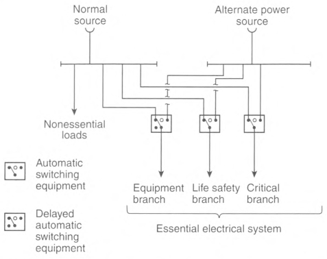
- The number of transfer switches to be used shall be based on reliability and design. Each branch of the essential electrical system shall have one or more transfer switches.
- One transfer switch shall be permitted to serve one or more branches in a facility with a continuous load on the switch of 150 kVA (120 kW) or less. [99:6.7.6.2.1.4]
Informational Note No. 1: See NFPA 99-2021, Health Care Facilities Code, 6.7.3.1, 6.7.2.2.5, 6.7.2.2.5.15, and 6.7.2.2.7, for more information on transfer switches.
Informational Note No. 2: See Informational Note Figure 517.31(B)(1).
Informational Note No. 3: See Informational Note Figure 517.31(B)(2).
Informational Note Figure 517.31(B)(1) Type 1 Essential Electrical System - Minimum Requirement (Greater Than 150 kVA) for Transfer Switch Arrangement..

Informational Note Figure 517.31(B)(2) Type 1 Essential Electrical System - Minimum Requirement (150 kVA or Less) for Transfer Switch Arrangement.
(1) Optional Loads.
Loads served by the generating equipment not specifically named in this article shall be served by their own transfer switches such that the following conditions apply:
(2) Contiguous Facilities.
Hospital power sources and alternate power sources shall be permitted to serve the essential electrical systems of contiguous or same-site facilities.
(C) Wiring Requirements.
(1) Separation From Other Circuits.
The life safety branch and critical branch [of the essential electrical system] shall be kept independent of all other wiring and equipment. [99:6.7.5.2.1]
- Raceways, cables, or enclosures of the life safety and critical branch shall be readily identified as components of the essential electrical system (EES). Boxes and enclosures (including transfer switches, generators, and power panels) shall be field- or factory-marked and identified as components of the EES. Raceways and cables shall be field- or factory-marked as components of the EES at intervals not to exceed 7.6 m (25 ft).
-
Conductors of the life safety branch or critical branch shall not enter the same raceways, boxes, or cabinets with each other or any other wiring system. Branch conductors shall be permitted to occupy common equipment, raceways, boxes, or cabinets of other circuits not part of the life safety branch and critical branch where such wiring complies with one of the following:
- Is in transfer equipment enclosures
- Is in exit or emergency luminaires supplied from two sources
- Is in a common junction box attached to exit or emergency luminaires supplied from two sources
- Is for two or more circuits supplied from the same branch and same transfer switch
- The wiring of the equipment branch shall be permitted to occupy the same raceways, boxes, or cabinets of other circuits that are not part of the essential electrical system.
- Where Category 2 locations are served from two separate transfer switches on the essential electrical system in accordance with 517.18(A), Exception No. 3, the Category 2 circuits from the two separate systems shall be kept independent of each other.
- Where Category 1 locations are served from two separate transfer switches on the essential electrical system in accordance with 517.19(A), Exception No. 2, the critical care circuits from the two separate systems shall be kept independent of each other.
(2) Isolated Power Systems.
Where isolated power systems are installed in any of the areas in 517.34(A)(1) and (A)(2), each system shall be supplied by an individual circuit serving no other load.
(3) Mechanical Protection of the Essential Electrical System.
The wiring of the life safety and critical branches shall be mechanically protected by raceways. Where installed as branch circuits in patient care spaces, the installation shall comply with the requirements of 517.13(A) and (B) and 250.118. Only the following wiring methods shall be permitted:
- Nonflexible metal raceways, Type MI cable, RTRC marked with the suffix —XW, or Schedule 80 PVC conduit. Nonmetallic raceways shall not be used for branch circuits that supply patient care spaces.
- Where encased in not less than 50 mm (2 in.) of concrete, Schedule 40 PVC conduit, flexible nonmetallic or jacketed metallic raceways, or jacketed metallic cable assemblies listed for installation in concrete. Nonmetallic raceways shall not be used for branch circuits that supply patient care spaces.
- Where used in listed prefabricated medical headwalls
- In listed office furnishings
- Where fished into existing walls or ceilings, not otherwise accessible and not subject to physical damage
- Where necessary for flexible connection to equipment
- For equipment that requires a flexible connection due to movement, vibration, or operation
- Luminaires installed in ceiling structures
- Flexible power cords of appliances or other utilization equipment connected to the essential electrical system.
- Cables for Class 2 or Class 3 systems permitted in Part VI of this article, with or without raceways.
Informational Note: See 517.13 for additional grounding requirements in patient care areas.
(D) Capacity of Systems.
The essential electrical system shall have the capacity and rating to meet the maximum actual demand likely to be produced by the connected load.
Feeders shall be sized in accordance with 215.2 and Part III of Article 220. The alternate power source(s) required in 517.30 shall have the capacity and rating to meet the demand produced by the load at any given time.
Demand calculations for sizing of the alternate power source(s) shall be based on any of the following:
- Prudent demand factors and historical data
- Connected load
- Feeder calculations
- Any combination of the above
(E) Receptacle Identification.
The electrical receptacles or the cover plates for the electrical receptacles supplied from the life safety and critical branches shall have a distinctive color or marking so as to be readily identifiable. [99:6.7.2.2.5(B)]
(F) Feeders From Alternate Power Source.
A single feeder supplied by a local or remote alternate power source shall be permitted to supply the essential electrical system to the point at which the life safety, critical, and equipment branches are separated. Installation of the transfer equipment shall be permitted at other than the location of the alternate power source.
(G) Coordination.
Overcurrent protective devices serving the essential electrical system shall be coordinated for the period of time that a fault's duration extends beyond 0.1 second.
Exception No. 1: Coordination shall not be required between transformer primary and secondary overcurrent protective devices where only one overcurrent protective device or set of overcurrent protective devices exists on the transformer secondary.
Exception No. 2: Coordination shall not be required between overcurrent protective devices of the same size (ampere rating) in series.
Informational Note No. 1: The terms coordination and coordinated as used in this section do not cover the full range of overcurrent conditions.
Informational Note No. 2: See 517.17(C) for information on requirements for the coordination of ground-fault protection.
517.32 Branches Requiring Automatic Connection.
(A) Life Safety and Critical Branch Used in a Type 1 EES.
Those functions of patient care depending on lighting or appliances that are connected to the essential electrical system shall be divided into the life safety branch and the critical branch, as described in 517.33 and 517.34.
(B) Life Safety and Critical Branch Used in a Type 2 EES.
The life safety and critical branches shall be installed and connected to the alternate power source specified in 517.41(A) and (B) so that all functions specified herein for the life safety and critical branches are automatically restored to operation within 10 seconds after interruption of the normal source. [99:6.7.5.3.1]
517.33 Life Safety Branch.
The life safety branch shall be limited to circuits essential to life safety. [99:6.7.5.1.2.3]
No functions other than those listed in 517.33(A) through (H) shall be connected to the life safety branch. The life safety branch shall supply power as follows:
(A) Illumination of Means of Egress.
Illumination of means of egress such as lighting required for corridors, passageways, stairways, and landings at exit doors, and all necessary ways of approach to exits. Switching arrangements to transfer patient corridor lighting in hospitals from general illumination circuits to night illumination circuits shall be permitted, if only one of two circuits can be selected and both circuits cannot be extinguished at the same time.
Informational Note: See NFPA 101-2021, Life Safety Code, Sections 7.8 and 7.9.
(B) Exit Signs.
Exit signs and exit directional signs.
Informational Note: See NFPA 101-2021, Life Safety Code, Section 7.10.
(C) Alarm and Alerting Systems.
Alarm and alerting systems including the following:
- Fire alarm systems
- Alarm and alerting systems (other than fire alarm systems) shall be connected to the life safety branch or critical branch. [99:6.7.5.1.2.5]
- Alarms for systems used for the piping of nonflammable medical gases
- Mechanical, control, and other accessories required for effective life safety systems operation shall be permitted to be connected to the life safety branch.
(D) Communications Systems.
Hospital communications systems, where used for issuing instructions during emergency conditions. [99:6.7.5.1.2.4(3)]
(E) Generator Set Locations.
Generator set locations as follows:
- Task illumination
- Battery charger for emergency battery-powered lighting unit(s)
- Select receptacles at the generator set location and essential electrical system transfer switch locations [99:6.7.5.1.2.4(4)]
(F) Generator Set Accessories.
Loads dedicated to a specific generator, including the fuel transfer pump(s), ventilation fans, electrically operated louvers, controls, cooling system, and other generator accessories essential for generator operation, shall be connected to the life safety branch or to the output terminals of the generator with overcurrent protective devices. [99:6.7.5.1.2.6]
(H) Automatic Doors.
Electrically powered doors used for building egress. [99:6.7.5.1.2.4(6)]
517.34 Critical Branch.
(A) Task Illumination, Fixed Equipment, and Select Receptacles.
The critical branch shall supply power for task illumination, fixed equipment, select receptacles, and select power circuits serving the following spaces and functions related to patient care:
- Category 1 spaces where deep sedation or general anesthesia is administered, task illumination, select receptacles, and fixed equipment
- Task illumination and select receptacles in the following:
- Patient care spaces, including infant nurseries, selected acute nursing areas, psychiatric bed areas (omit receptacles), and ward treatment rooms
- Medication preparation spaces
- Pharmacy dispensing spaces
- Nurses' stations - unless adequately lighted by corridor luminaires
- Additional specialized patient care task illumination and receptacles, where needed
- Nurse call systems
- Blood, bone, and tissue banks
- Telecommunications entrance facility, telecommunications equipment rooms, and telecommunication rooms and equipment in these rooms
- Task illumination, select receptacles, and select power circuits for the following areas:
- Category 1 or 2 spaces with at least one duplex receptacle per patient bed location, and task illumination as required by the governing body of the health care facility
- Angiographic labs
- Cardiac catheterization labs
- Coronary care units
- Hemodialysis rooms or areas
- Emergency room treatment areas (select)
- Human physiology labs
- Intensive care units
- Postoperative recovery rooms (select)
- Clinical IT-network equipment
- Wireless phone and paging equipment for clinical staff communications
- Additional task illumination, receptacles, and select power circuits needed for effective facility operation, including single-phase fractional horsepower motors, which are permitted to be connected to the critical branch
[99:6.7.5.1.3.2]
(C) Subdivision of the Critical Branch.
The critical branch shall be permitted to be subdivided into two or more branches. [99:6.7.5.1.3.1]
Informational Note: It is important to analyze the consequences of supplying an area with only critical branch power when failure occurs between the area and the transfer switch. Some proportion of normal and critical power or critical power from separate transfer switches might be appropriate.
517.35 Equipment Branch Connection to Alternate Power Source.
The equipment branch shall be installed and connected to the alternate power source such that the equipment described in 517.35(A) is automatically restored to operation at appropriate time-lag intervals following the energizing of the life safety and critical branches. [99:6.7.5.1.4.2(A)]
The arrangement of the connection to the alternate power source shall also provide for the subsequent connection of equipment described in 517.35(B). [99:6.7.5.1.4.2(B)].
Exception: For essential electrical systems under 150 kVA, deletion of the time-lag intervals feature for delayed automatic connection to the equipment system shall be permitted.
(A) Equipment for Delayed Automatic Connection.
The following equipment shall be permitted to be arranged for delayed automatic connection to the alternate power source:
- Central suction systems serving medical and surgical functions, including controls, with such suction systems permitted to be placed on the critical branch
- Sump pumps and other equipment required to operate for the safety of major apparatus, including associated control systems and alarms
- Compressed air systems serving medical and surgical functions, including controls with such air systems permitted to be placed on the critical branch
- Smoke control and stair pressurization systems
- Kitchen hood supply or exhaust systems, or both, if required to operate during a fire in or under the hood
- Supply, return, and exhaust ventilating systems for the following:
- Airborne infectious/isolation rooms
- Protective environment rooms
- Exhaust fans for laboratory fume hoods
- Nuclear medicine areas where radioactive material is used
- Ethylene oxide evacuation
- Anesthetic evacuation
- Supply, return, and exhaust ventilating systems for operating and delivery rooms
- Supply, return, exhaust ventilating systems and/or air-conditioning systems serving telephone equipment rooms and closets and data equipment rooms and closets
Exception: Sequential delayed automatic connection to the alternate power source to prevent overloading the generator shall be permitted where engineering studies indicate it is necessary.
(B) Equipment for Delayed Automatic or Manual Connection.
The following equipment shall be permitted to be arranged for either delayed automatic or manual connection to the alternate power source:
- Heating equipment to provide heating for operating, delivery, labor, recovery, intensive care, coronary care, nurseries, infection/isolation rooms, emergency treatment spaces, and general patient rooms and pressure maintenance (jockey or make-up) pump(s) for water-based fire protection systemsException: Healing of general patient rooms and infection/isolation rooms during disruption of the normal source shall not be required under any of the following conditions:
- The outside design temperature is higher than —6.7°C (20°F).
- The outside design temperature is lower than —6.7°C (20°F), and where a selected room(s) is provided for the needs of all confined patients, only such room(s) need be heated.
- The facility is served by a dual source of normal power.Informational Note No. 1: The design temperature is based on the 97.5 percent design value as shown in Chapter 24 of the ASHRAE Handbook of Fundamentals (2013).Informational Note No. 2: See 517.30(C) for a description of a dual source of normal power.
- An elevator(s) selected to provide service to patient, surgical, obstetrical, and ground floors during interruption of normal power. In instances where interruption of normal power would result in other elevators stopping between floors, throw-over facilities shall be provided to allow the temporary operation of any elevator for the release of patients or other persons who may be confined between floors.
- Hyperbaric facilities.
- Hypobaric facilities.
- Automatically operated doors.
- Minimal electrically heated autoclaving equipment shall be permitted to be arranged for either automatic or manual connection to the alternate source.
- Controls for equipment listed in 517.35.
- Other selected equipment shall be permitted to be served by the equipment system. [99:6.7.5.1.4.4]
517.40 Type 2 Essential Electrical Systems.
Informational Note No. 1: Nursing homes and other limited care facilities can contain Category 1 and/or Category 2 patient care spaces, depending on the design and type of care administered in the facility. For Category 1 spaces, see 517.29 through 517.35. For Category 2 spaces not served by Type 1 essential electrical systems, see 517.40 through 517.44.
Informational Note No. 2: Type 2 essential electrical systems are comprised of two separate branches capable of supplying a limited amount of lighting and power service that is considered essential for the protection of life and safety and effective operation of the institution during the time normal electrical service is interrupted for any reason. These two separate branches are the life safety and equipment branches. The number of transfer switches to be used should be based upon reliability, design, and load considerations. Each branch of the essential electrical system should have one or more transfer switches. One transfer switch should be permitted to serve one or more branches in a facility with a maximum demand on the essential electrical system of 150 kVA (120 kW). [99:A.6.7.6.2.1]
(A) Applicability.
The requirements of 517.40(C) through 517.44 shall apply to Category 2 spaces.
Exception: The requirements of 517.40(C) through 517.44 shall not apply to freestanding buildings used as nursing homes and limited care facilities if the following apply:
(1) Admitting and discharge policies are maintained that preclude the provision of care for any patient or resident who might need to be sustained by electrical life-support equipment.
(2) No surgical treatment requiring general anesthesia is offered.
(3) An automatic battery-operated system(s) or equipment shall be effective for at least 11/2 hours and is otherwise in accordance with 700.12 and that shall be capable of supplying lighting for exit lights, exit corridors, stairways, nursing stations, medical preparation areas, boiler rooms, and communications areas. This system shall also supply power to operate all alarm systems.
Informational Note: See NFPA 101-2021, Life Safety Code.
(B) Category 1 Spaces in Inpatient Hospital Care Facilities.
For those nursing homes and limited care facilities that admit patients who need to be sustained by electrical life-support equipment, the essential electrical system from the source to the portion of the facility where such patients are treated shall comply with the requirements of 517.29 through 517.35.
(C) Facilities Contiguous or Located on the Same Site With Hospitals.
Nursing homes and limited care facilities that are contiguous or located on the same site with a hospital shall be permitted to have their essential electrical systems supplied by the hospital.
517.41 Required Power Sources.
(A) Independent Power Sources.
Essential electrical systems (EES) shall have two or more independent sources (or sets of sources). One on-site source (or sets of sources) shall be sized to supply the entire EES. The other independent source (or sets of sources) shall be sized to supply the entire EES and shall be permitted to be located on-site or off-site. Additional sources other than the first two independent sources shall be permitted to be sized to supply the intended load.
Informational Note: An example of a set of sources may be several generators that combined serve the entire EES.
(B) Location of EES Components.
EES components shall be located to minimize interruptions caused by natural forces common to the area (e.g., storms, floods, earthquakes, or hazards created by adjoining structures or activities). [99:6.2.4.1]
517.42 Essential Electrical Systems for Nursing Homes and Limited Care Facilities.
(A) General.
The [Type 2] essential electrical system shall be divided into the following two branches:
- Life safety branch
- Equipment branch [99:6.7.6.2.1.2]
Informational Note No. 2: The number of transfer switches to be used should be based upon reliability, design, and load considerations. Each branch of the essential electrical system should have one or more transfer switches. One transfer switch should be permitted to serve one or more branches in a facility with a maximum demand on the essential electrical system of 150 kVA (120 kW). [99:A.6.7.6.2.1].
Informational Note No. 3: See NFPA 99-2021, Health Care Facilities Code, 6.7.2.2, for more information.
(B) Transfer Switches.
The number of transfer switches to be used shall be based upon reliability, design, and load considerations. [99:6.7.2.2.3] 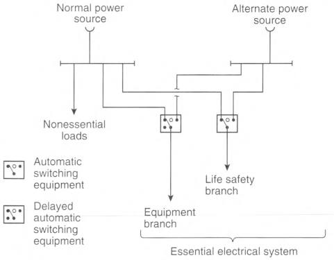
Transfer switches shall be in accordance with one of the following:
- Each branch of the essential electrical system shall have one or more transfer switches. [99:6.7.2.2.3.1]
- One transfer switch shall be permitted to serve one or more branches in a facility with a continuous load on the switch of 150 kVA (120 kW) or less. [99:6.7.2.2.3.2]
Informational Note No. 1: See NFPA 99-2021, Health Care Facilities Code, 6.7.2.2.4, 6.7.2.2.5, 6.7.2.2.5.15, and 6.7.2.2.7 for more information on transfer switches.
Informational Note No. 2: See Informational Note Figure 517.42(B)(1).
Informational Note No. 3: See Informational Note Figure 517.42(B)(2).
Informational Note Figure 517.42(B)(1) Type 2 Essential Electrical Systems (Nursing Home and Limited Health Care Facilities) - Minimum Requirement (Greater Than 150 kVA) for Transfer Switch Arrangement..
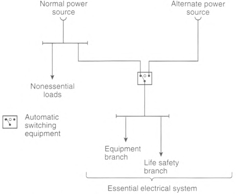
Informational Note Figure 517.42(B)(2) Type 2 Essential Electrical Systems (Nursing Home and Limited Health Care Facilities) - Minimum Requirement (150 kVA or Less) for Transfer Switch Arrangement.
(C) Capacity of System.
The essential electrical system shall have capacity to meet the demand for the operation of all functions and equipment to be served by each branch at one time.
(D) Separation From Other Circuits.
The life safety branch and equipment branch shall be kept entirely independent of all other wiring and equipment. [99:6.7.6.3.1]
These circuits shall not enter the same raceways, boxes, or cabinets with other wiring except as follows:
- In transfer switches
- In exit or emergency luminaires supplied from two sources
- In a common junction box attached to exit or emergency luminaires supplied from two sources
(E) Receptacle Identification.
The electrical receptacles or the cover plates for the electrical receptacles supplied from the life safety or equipment branches shall have a distinctive color or marking so as to be readily identifiable. [99:6.7.6.3.2]
Informational Note: If color is used to identify these receptacles, the same color should be used throughout the facility. [99:A.6.7.6.3.2]
517.43 Automatic Connection to Life Safety and Equipment Branch.
The life safety and equipment branches shall be installed and connected to the alternate source of power specified in 517.41 so that all functions specified herein for the life safety and equipment branches are automatically restored to operation within 10 seconds after interruption of the normal source. [99:6.7.6.4.1]
No functions other than those listed in 517.43(A) through (G) shall be connected to the life safety branch. [99:6.7.6.2.1.5(D)].
The life safety branch shall supply power as follows:
(A) Illumination of Means of Egress.
Illumination of means of egress as is necessary for corridors, passageways, stairways, landings, and exit doors and all ways of approach to exits. Switching arrangement to transfer patient corridor lighting from general illumination circuits shall be permitted if only one of two circuits can be selected and both circuits cannot be extinguished at the same time.
Informational Note: See NFPA 101-2021, Life Safety Code, Sections 7.8 and 7.9.
(B) Exit Signs.
Exit signs and exit directional signs.
Informational Note: See NFPA 101-2021, Life Safety Code, Section 7.10.
(C) Alarm and Alerting Systems.
Alarm and alerting systems, including the following:
- Fire alarmsInformational Note No. 1: See NFPA 101-2021, Life Safety Code, Sections 9.6 and 18.3.4.
- Alarms required for systems used for the piping of nonflammable medical gases
Informational Note No. 2: See NFPA 99-2021, Health Care Facilities Code, 6.7.5.1.2.5.
(D) Communications Systems.
Communications systems, where used for issuing instructions during emergency conditions. [99:6.7.5.1.2.4(3)]
(E) Generator Set Location.
Task illumination and select receptacles at the generator set location and essential electrical system transfer switch locations.
(G) AC Equipment for Nondelayed Automatic Connection.
Generator accessories, including, but not limited to, the transfer fuel pump, electrically operated louvers, and other generator accessories essential for generator operation shall be arranged for automatic connection to the alternate power source. [99:6.7.6.2.1.6(C)]
517.44 Connection to Equipment Branch.
The equipment branch shall be installed and connected to the alternate power source such that equipment described in 517.35(A)(6) is automatically restored to operation at appropriate time-lag intervals following the energizing of the life safety and critical branches. [99:6.7.5.1.4.2(A)]
The equipment branch arrangement shall also provide for the additional connection of equipment listed in 517.44(B).
Exception: For essential electrical systems under 150 kVA, deletion of the time-lag intervals feature for delayed automatic connection to the equipment branch shall be permitted.
(A) Delayed Automatic Connections to Equipment Branch.
The following equipment shall be permitted to be connected to the equipment branch and shall be arranged for delayed automatic connection to the alternate power source:
- Supply, return, and exhaust ventilating systems for airborne infectious isolation rooms [99:6.7.6.2.1.6(D)(2)]
- Sump pumps and other equipment required to operate for the safety of major apparatus and associated control systems and alarms [99:6.7.6.2.1.6(D)(3)]
- Smoke control and stair pressurization systems [99:6.7.6.2.1.6(D)(4)]
- Kitchen hood supply or exhaust systems, or both, if required to operate during a fire in or under the hood [99:6.7.6.2.1.6(D)(5)]
- Nurse call systems [99:6.7.6.2.1.6(D)(6)]
Task illumination and select receptacles in the following: [99:6.7.6.2.1.6(D)(1)].
- Patient care spaces [99:6.7.6.2.1.6(D)(1)(a)]
- Medication preparation spaces [99:6.7.6.2.1.6(D)(1)(b)]
- Pharmacy dispensing space [99:6.7.6.2.1.6(D)(1)(c)]
- Nurses' stations - unless adequately lighted by corridor luminaires [99:6.7.6.2.1.6(D)(1)(d)]
(B) Delayed-Automatic or Manual Connection to the Equipment Branch.
The equipment specified in 517.44(B)(1) through (B)(4) shall be permitted to be connected to the equipment branch and shall be arranged for either delayed-automatic or manual connection to the alternate power source.
(1) Heating Equipment to Provide Heating for General Patient Rooms.
Heating of general patient rooms during disruption of the normal source shall not be required under any of the following conditions:
- The outside design temperature is higher than —6.7°C (20°F).
- The outside design temperature is lower than —6.7°C (20°F) and, where a selected room(s) is provided for the needs of all confined patients, then only such room(s) need be heated.
- The facility is served by a dual source of normal power as described in 517.30(C), Informational Note.
Informational Note: The outside design temperature is based on the 97.5 percent design values, as shown in Chapter 24 of the ASHRAE Handbook of Fundamentals (2013).
(2) Elevator Service.
In instances where interruptions of power would result in elevators stopping between floors, throw-over facilities shall be provided to allow the temporary operation of any elevator for the release of passengers.
(3) Optional Connections to the Equipment Branch.
Additional illumination, receptacles, and equipment shall be permitted to be connected only to the equipment branch.
(4) Multiple Systems.
Where one switch serves multiple systems as permitted in 517.43, transfer for all loads shall be nondelayed automatic.
517.45 Essential Electrical Systems for Other Health Care Facilities.
(A) Essential Electrical Distribution.
If required by the governing body, the essential electrical distribution system for Category 3 patient care spaces shall be comprised of an alternate power system capable of supplying a limited amount of lighting and power service for the orderly cessation of procedures during a time normal electrical service is interrupted.
Informational Note: See NFPA 99-2021, Health Care Facilities Code.
(B) Electrical Life Support Equipment.
Where electrical life support equipment is required, the essential electrical distribution system shall be as described in 517.29 through 517.30.
(C) Category 1 Patient Care Spaces.
Where Category 1 patient care spaces are present, the essential electrical distribution system shall be in accordance with 517.29 through 517.30.
(D) Category 2 Patient Care Spaces.
Where Category 2 patient care spaces are present, the essential electrical distribution system shall be in accordance with 517.40 through 517.45.
(E) Power Systems.
If required, alternate power sources acceptable to the governing body shall comply with the requirements of NFPA 99-2021, Health Care Facilities Code.
Part IV. Inhalation Anesthetizing Locations
Informational Note: See NFPA 99-2021, Health Care Facilities Code, for further information regarding safeguards for anesthetizing locations.
517.60 Anesthetizing Location Classification.
(A) Hazardous (Classified) Location.
(1) Use Location.
In a location where flammable anesthetics are employed, the entire area shall be considered to be a Class I, Division 1 location that extends upward to a level 1.52 m (5 ft) above the floor. The remaining volume up to the structural ceiling is considered to be above a hazardous (classified) location.
(2) Storage Location.
Any room or location in which flammable anesthetics or volatile flammable disinfecting agents are stored shall be considered to be a Class I, Division 1 location from floor to ceiling.
517.61 Wiring and Equipment.
(A) Within Hazardous (Classified) Anesthetizing Locations.
(1) Isolation.
Except as permitted in 517.160, each power circuit within, or partially within, a flammable anesthetizing location as referred to in 517.60 shall be isolated from any distribution system by the use of an isolated power system.
(2) Design and Installation.
Where an isolated power system is utilized, the isolated power equipment shall be listed as isolated power equipment, and the isolated power system shall be designed and installed in accordance with 517.160.
(3) Equipment Operating at More Than 10 Volts.
In hazardous (classified) locations referred to in 517.60, all fixed wiring and equipment and all portable equipment, including lamps and other utilization equipment, operating at more than 10 volts between conductors shall comply with the requirements of 501.1 through 501.25, and 501.100 through 501.150, and 501.30(A) and (B) for Class I, Division 1 locations. All such equipment shall be specifically approved for the hazardous atmospheres involved.
(5) Receptacles and Attachment Plugs.
Receptacles and attachment plugs in a hazardous (classified) location(s) shall be listed for use in Class I, Group C hazardous (classified) locations and shall have provision for the connection of an equipment grounding conductor.
(6) Flexible Cord Type.
Flexible cords used in hazardous (classified) locations for connection to portable utilization equipment, including lamps operating at more than 8 volts between conductors, shall be of a type approved for extra-hard usage in accordance with Table 400.4 and shall include an additional equipment grounding conductor.
(B) Above Hazardous (Classified) Anesthetizing Locations.
(2) Equipment Enclosure.
Installed equipment that may produce arcs, sparks, or particles of hot metal, such as lamps and lampholders for fixed lighting, cutouts, switches, generators, motors, or other equipment having make-and-break or sliding contacts, shall be of the totally enclosed type or be constructed so as to prevent escape of sparks or hot metal particles.
Exception: Wall-mounted receptacles installed above the hazardous (classified) location in flammable anesthetizing locations shall not be required to be totally enclosed or have openings guarded or screened to prevent dispersion of particles.
(3) Luminaires.
Surgical and other luminaires shall conform to 501.130(B).
Exception No. 1: The surface temperature limitations set forth in 501.130(B)(1) shall not apply.
Exception No. 2: Integral or pendant switches that are located above and cannot be lowered into the hazardous (classified) location(s) shall not be required to be explosionproof.
(4) Seals.
Listed seals shall be provided in conformance with 501.15, and 501.15(A)(4) shall apply to horizontal as well as to vertical boundaries of the defined hazardous (classified) locations.
(5) Receptacles and Attachment Plugs.
Receptacles and attachment plugs located above hazardous (classified) anesthetizing locations shall be listed for hospital use for services of prescribed voltage, frequency, rating, and number of conductors with provision for the connection of the equipment grounding conductor. This requirement shall apply to attachment plugs and receptacles of the 2-pole, 3-wire grounding type for single-phase, 120-volt, nominal, ac service.
(6) 250-Volt Receptacles and Attachment Plugs Rated 50 and 60 Amperes.
Receptacles and attachment plugs rated 250 volts, for connection of 50-ampere and 60-ampere ac medical equipment for use above hazardous (classified) locations, shall be arranged so that the 60-ampere receptacle will accept either the 50-ampere or the 60-ampere plug. Fifty-ampere receptacles shall be designed so as not to accept the 60-ampere attachment plug. The attachment plugs shall be of the 2-pole, 3-wire design with a third contact connecting to the insulated (green or green with yellow stripe) equipment grounding conductor of the electrical system.
(C) Unclassified Anesthetizing Locations.
(1) Wiring Methods.
Wiring serving unclassified locations, as defined in 517.60, shall be installed in a metal raceway system or cable assembly. The metal raceway system or cable armor or sheath assembly shall qualify as an equipment grounding conductor in accordance with 250.118. Type MC and Type MI cable shall have an outer metal armor, sheath, or sheath assembly that is identified as an equipment grounding conductor.
Exception: Pendant receptacle installations that employ listed Type SJO or equivalent hard usage or extra-hard usage, flexible cords suspended not less than 1.8 m (6 ft) from the floor shall not be required, to be installed in a metal raceway or cable assembly.
(2) Receptacles and Attachment Plugs.
Receptacles and attachment plugs installed and used in unclassified locations shall be listed "hospital grade" for services of prescribed voltage, frequency, rating, and number of conductors with provision for connection of the equipment grounding conductor. This requirement shall apply to 2-pole, 3-wire grounding type for single-phase, 120-, 208-, or 240-volt, nominal, ac service.
(3) 250-Volt Receptacles and Attachment Plugs Rated 50 Amperes and 60 Amperes.
Receptacles and attachment plugs rated 250 volts, for connection of 50-ampere and 60-ampere ac medical equipment for use in unclassified locations, shall be arranged so that the 60-ampere receptacle will accept either the 50-ampere or the 60-ampere plug. Fifty-ampere receptacles shall be designed so as not to accept the 60-ampere attachment plug. The attachment plugs shall be of the 2-pole, 3-wire design with a third contact connecting to the insulated (green or green with yellow stripe) equipment grounding conductor of the electrical system.
517.62 Grounding.
In any anesthetizing area, all metal raceways and metal-sheathed cables and all normally non—current-carrying conductive portions of fixed electrical equipment shall be connected to an equipment grounding conductor. Grounding and bonding in Class I locations shall comply with 501.30.
Exception: Equipment operating at not more than 10 volts between conductors shall not be required to be connected to an equipment grounding conductor.
517.63 Grounded Power Systems in Anesthetizing Locations.
(A) Battery-Powered Lighting Units.
One or more battery-powered lighting units shall be provided and shall be permitted to be wired to the critical lighting circuit in the area and connected ahead of any local switches.
(B) Branch-Circuit Wiring.
Branch circuits supplying only listed, fixed, therapeutic and diagnostic equipment, permanently installed above the hazardous (classified) location and in unclassified locations, shall be permitted to be supplied from a normal grounded service, single- or three-phase system, provided the following apply:
- Wiring for grounded and isolated circuits does not occupy the same raceway or cable.
- All conductive surfaces of the equipment are connected to an equipment grounding conductor.
- Equipment (except enclosed X-ray tubes and the leads to the tubes) is located at least 2.5 m (8 ft) above the floor or outside the anesthetizing location.
- Switches for the grounded branch circuit are located outside the hazardous (classified) location.
Exception: Sections 517.63(B)(3) and (B)(4) shall not apply in unclassified locations.
(C) Fixed Lighting Branch Circuits.
Branch circuits supplying only fixed lighting shall be permitted to be supplied by a normal grounded service, provided the following apply:
- Such luminaires are located at least 2.5 m (8 ft) above the floor.
- All conductive surfaces of luminaires are connected to an equipment grounding conductor.
- Wiring for circuits supplying power to luminaires does not occupy the same raceway or cable for circuits supplying isolated power.
- Switches are wall-mounted and located above hazardous (classified) locations.
Exception: Sections 517.63(C)(1) and (C)(4) shall not apply in unclassified locations.
(E) Location of Isolated Power Systems.
Where an isolated power system is utilized, the isolated power equipment shall be listed as isolated power equipment. Isolated power system equipment and its supply circuit shall be permitted to be located in an anesthetizing location, provided it is installed above a hazardous (classified) location or in an unclassified location.
517.64 Low-Voltage Equipment and Instruments.
(B) Power Supplies.
Power shall be supplied to low-voltage equipment from one of the following:
- An individual portable isolating transformer (autotransformers shall not be used) connected to an isolated power circuit receptacle by means of an appropriate cord and attachment plug
- A common low-voltage isolating transformer installed in an unclassified location
- Individual dry-cell batteries
- Common batteries made up of storage cells located in an unclassified location
(C) Isolated Circuits.
Isolating-type transformers for supplying low-voltage circuits shall have both of the following:
- Approved means for insulating the secondary circuit from the primary circuit
- The core and case connected to an equipment grounding conductor
(E) Battery-Powered Appliances.
Battery-powered appliances shall not be capable of being charged while in operation unless their charging circuitry incorporates an integral isolating-type transformer.
(F) Receptacles or Attachment Plugs.
Any receptacle or attachment plug used on low-voltage circuits shall be of a type that does not permit interchangeable connection with circuits of higher voltage.
Informational Note: Any interruption of the circuit, even circuits as low as 10 volts, either by any switch or loose or defective connections anywhere in the circuit, may produce a spark that is sufficient to ignite flammable anesthetic agents.
517.70 Applicability.
Nothing in this part shall be construed as specifying safeguards against possible radiation or magnetic fields.
Informational Note No. 1: Radiation safety and performance requirements of several classes of X-ray equipment are regulated under Public Law 90-602 and are enforced by the Department of Health and Human Services.
Informational Note No. 2: Information on radiation protection by the National Council on Radiation Protection and Measurements is published as Reports of the National Council on Radiation Protection and Measurement. These reports are obtainable from NCRP Publications, P.O. Box 30175, Washington, DC 20014.
Informational Note No. 3: Examples of diagnostic imaging equipment can include, but are not limited to, the following:
- General radiographic (X-ray) equipment (mobile and fixed)
- General fluoroscopic equipment (mobile and fixed)
- Interventional equipment (mobile and fixed)
- Bone mineral density equipment
- Dental equipment
- Computerized tomography (CT) equipment
- Positron emission tomography (PET) equipment
- Nuclear medicine equipment
- Mammography equipment
- Magnetic resonance (MR) equipment
- Diagnostic ultrasound equipment
- Electrocardiogram equipment
Informational Note No. 4: Examples of treatment equipment can include, but are not limited to, the following:
- Linear accelerators
- Gamma knife
- Cyber knife
- Proton therapy
- Tomotherapy
517.71 Connection to Supply Circuit.
(A) Fixed and Stationary Diagnostic Imaging and Treatment Equipment.
Fixed and stationary diagnostic imaging and treatment equipment shall be connected to the power supply by means of a wiring method complying with applicable requirements of Chapters 1 through 4 of this Code, as modified by this article.
Exception: Equipment properly supplied by a branch circuit rated at not over 30 amperes shall be permitted to be supplied through a suitable attachment plug and hard-service cable or cord.
(B) Portable, Mobile, and Transportable Diagnostic Imaging and Treatment Equipment.
Individual branch circuits shall not be required for portable, mobile, and transportable medical diagnostic imaging and treatment equipment requiring a capacity of not over 60 amperes.
(C) Over 1000 Volt Supply.
Circuits and equipment operated on a supply circuit of over 1000 volts shall comply with Parts I through IV of Article 495.
517.72 Disconnecting Means.
(A) Capacity.
A disconnecting means rated for at least 50 percent of the input required for the momentary rating or 100 percent of the input required for the long-time rating of the diagnostic imaging and treatment equipment, whichever is greater, shall be provided in the supply circuit.
(B) Location.
The disconnecting means shall be operable from a location readily accessible from the control location.
(C) Portable, Mobile, and Transportable Diagnostic Imaging and Treatment Equipment.
For equipment connected to a 120-volt branch circuit of 30 amperes or less, a grounding-type attachment plug and receptacle of proper rating shall be permitted to serve as a disconnecting means.
517.73 Rating of Supply Conductors and Overcurrent Protection.
(A) Branch Circuits.
The ampacity of supply branch-circuit conductors and the current rating of overcurrent protective devices shall not be less than 50 percent of the momentary rating or 100 percent of the long-time rating, whichever is greater.
(B) Feeders.
The ampacity of supply feeders and the current rating of overcurrent protective devices supplying two or more branch circuits supplying diagnostic imaging and treatment equipment shall not be less than 50 percent of the momentary demand rating of the largest unit, plus 25 percent of the momentary demand rating of the next largest unit, plus 10 percent of the momentary demand rating of each additional unit.
Informational Note No. 1: The minimum conductor size for branch and feeder circuits is also governed by voltage regulation requirements. For a specific installation, the manufacturer usually specifies minimum distribution transformer and conductor sizes, rating of disconnecting means, and overcurrent protection.
Informational Note No. 2: The ampacity of the branch-circuit conductors and the ratings of disconnecting means and overcurrent protection for diagnostic imaging and treatment equipment are usually designated by the manufacturer for the specific installation.
517.74 Control Circuit Conductors.
(A) Number of Conductors in Raceway.
The number of control circuit conductors installed in a raceway shall be determined in accordance with 300.17.
517.76 Transformers and Capacitors.
Transformers and capacitors that are part of diagnostic imaging and treatment equipment shall not be required to comply with Parts I and II of Articles 450 and 460.
Capacitors shall be mounted within enclosures of insulating material or grounded metal.
517.77 Installation of Cables With Grounded Shields.
Cables with grounded shields shall be permitted to be installed in cable trays or cable troughs along with control and power supply conductors without the need for barriers to separate the wiring.
517.78 Guarding and Grounding.
(B) Low-Voltage Cables.
Low-voltage cables connecting to oil-filled units that are not completely sealed, such as transformers, condensers, oil coolers, and high-voltage switches, shall have insulation of the oil-resistant type.
(C) Non-Current-Carrying Metal Parts.
Non-current-carrying metal parts of diagnostic imaging and treatment equipment (e.g., controls, tables, transformer tanks, shielded cables) shall be connected to an equipment grounding conductor in accordance with Part VII of Article 250, as modified by 517.13(A) and (B).
517.80 Patient Care Spaces.
Equivalent insulation and isolation to that required for the electrical distribution systems in patient care areas shall be provided for communications, signaling systems, data system circuits, fire alarm systems, and systems less than 120 volts, nominal.
Class 2 and Class 3 signaling and communications systems, Class 2 circuits that transmit power and data to a powered device, and power-limited fire alarm systems shall not be required to comply with the grounding requirements of 517.13, to comply with the mechanical protection requirements of 517.31(C)(3)(5), or to be enclosed in raceways, unless otherwise specified by Chapters 7 or 8.
Secondary circuits of transformer-powered communications or signaling systems shall not be required to be enclosed in raceways unless otherwise specified by Chapters 7 or 8. [99:6.7.2.2.7].
Informational Note: See ANSI/NEMA C137.3-2017, American National Standard for Lighting Systems - Minimum Requirements for Installation of Energy Efficient Power over Ethernet (PoE) Lighting Systems, for information on installation of cables for PoE lighting systems.
517.81 Other-Than-Patient-Care Spaces.
In other-than-patient-care spaces, installations shall be in accordance with other parts of this Code.
517.82 Signal Transmission Between Appliances.
(A) General.
Permanently installed signal cabling from an appliance in a patient location to remote appliances shall employ a signal transmission system that prevents hazardous grounding interconnection of the appliances.
Informational Note: See 517.13(A) for additional grounding requirements in patient care spaces.
(B) Common Signal Grounding Wire.
Common signal grounding wires (i.e., the chassis ground for single-ended transmission) shall be permitted to be used between appliances all located within the patient care vicinity, provided the appliances are served from the same reference grounding point.
517.160 Isolated Power Systems.
(A) Installations.
(1) Isolated Power Circuits.
Each isolated power circuit shall be controlled by a switch or circuit breaker that has a disconnecting pole in each isolated circuit conductor to simultaneously disconnect all power. Such isolation shall be accomplished by means of one or more isolation transformers, by means of generator sets, or by means of electrically isolated batteries. Conductors of isolated power circuits shall not be installed in cables, raceways, or other enclosures containing conductors of another system.
(2) Circuit Characteristics.
Circuits supplying primaries of isolating transformers shall operate at not more than 600 volts between conductors and shall be provided with proper overcurrent protection. The secondary voltage of such transformers shall not exceed 600 volts between conductors of each circuit. All circuits supplied from such secondaries shall be ungrounded and shall have an approved overcurrent device of proper ratings in each conductor. Circuits supplied directly from batteries or from motor generator sets shall be ungrounded and shall be protected against overcurrent in the same manner as transformer-fed secondary circuits. If an electrostatic shield is present, it shall be connected to the reference grounding point.
(3) Equipment Location.
The isolating transformers, motor generator sets, batteries and battery chargers, and associated primary or secondary overcurrent devices shall not be installed in hazardous (classified) locations. The isolated secondary circuit wiring extending into a hazardous anesthetizing location shall be installed in accordance with 501.10.
(4) Isolation Transformers.
An isolation transformer shall not serve more than one operating room except as covered in 517.160(A)(4)(a) and (A)(4)(b).
For purposes of this section, anesthetic induction rooms are considered part of the operating room or rooms served by the induction rooms.
- Induction Rooms. Where an induction room serves more than one operating room, the isolated circuits of the induction room shall be permitted to be supplied from the isolation transformer of any one of the operating rooms served by that induction room.
- Higher Voltages. Isolation transformers shall be permitted to serve single receptacles in several patient areas where the following apply:
- The receptacles are reserved for supplying power to equipment requiring 150 volts or higher, such as portable X-ray units.
- The receptacles and mating plugs are not interchangeable with the receptacles on the local isolated power system.
(5) Conductor Identification.
The isolated circuit conductors shall be identified as follows:
- Isolated Conductor No. 1 - Orange with at least one distinctive colored stripe other than white, green, or gray along the entire length of the conductor
- Isolated Conductor No. 2 - Brown with at least one distinctive colored stripe other than white, green, or gray along the entire length of the conductor
For 3-phase systems, the third conductor shall be identified as yellow with at least one distinctive colored stripe other than white, green, or gray along the entire length of the conductor. Where isolated circuit conductors supply 125-volt, single-phase, 15- and 20-ampere receptacles, the striped orange conductor(s) shall be connected to the terminal(s) on the receptacles that are identified in accordance with 200.10(B) for connection to the grounded circuit conductor.
(6) Wire-Pulling Compounds.
Wire-pulling compounds that increase the dielectric constant shall not be used on the secondary conductors of the isolated power supply.
Informational Note No. 1: It is desirable to limit the size of the isolation transformer to 10 kVA or less and to use conductor insulation with low leakage to meet impedance requirements.
Informational Note No. 2: Minimizing the length of branch-circuit conductors and using conductor insulations with a dielectric constant less than 3.5 and insulation resistance constant greater than 6100 megohm-meters (20,000 megohm-feet) at 16°C (60°F) reduces leakage from line to ground, reducing the hazard current.
(B) Line Isolation Monitor.
(1) Characteristics.
In addition to the usual control and over-current protective devices, each isolated power system shall be provided with a listed continually operating line isolation monitor that indicates total hazard current. The monitor shall be designed such that a green signal lamp, conspicuously visible to persons in each area served by the isolated power system, remains lighted when the system is adequately isolated from ground. An adjacent red signal lamp and an audible warning signal (remote if desired) shall be energized when the total hazard current (consisting of possible resistive and capacitive leakage currents) from either isolated conductor to ground reaches a threshold value of 5 mA under nominal line voltage conditions. The line monitor shall not alarm for a fault hazard of less than 3.7 mA or for a total hazard current of less than 5 mA.
Exception: A system shall be permitted to be designed to operate at a lower threshold value of total hazard current. A line isolation monitor for such a system shall be permitted to be approved, with the provision that the fault hazard current shall be permitted to be reduced but not to less than 35 percent of the corresponding threshold value of the total hazard current, and the monitor hazard current is to be correspondingly reduced to not more than 50 percent of the alarm threshold value of the total hazard current.
(2) Impedance.
The line isolation monitor shall be designed to have sufficient internal impedance such that, when properly connected to the isolated system, the maximum internal current that can flow through the line isolation monitor, when any point of the isolated system is grounded, shall be 1 mA.
Exception: The line isolation monitor shall be permitted to be of the low-impedance type such that the current through the line isolation monitor, when any point of the isolated system is grounded, will not exceed twice the alarm threshold value for a period not exceeding 5 milliseconds.
Informational Note: Reduction of the monitor hazard current, provided this reduction results in an increased "not alarm" threshold value for the fault hazard current, will increase circuit capacity.
(3) Ammeter.
An ammeter calibrated in the total hazard current of the system (contribution of the fault hazard current plus monitor hazard current) shall be mounted in a plainly visible place on the line isolation monitor with the "alarm on" zone at approximately the center of the scale.
Exception: The line isolation monitor shall be permitted to be a composite unit, with a sensing section cabled to a separate display panel section on which the alarm or test functions are located.
Informational Note: It is desirable to locate the ammeter so that it is conspicuously visible to persons in the anesthetizing location.
Article 518
Assembly Occupancies
518.1 Scope.
Except for the assembly occupancies explicitly covered by 520.1, this article covers all buildings or portions of buildings or structures designed or intended for the gathering together of 100 or more persons for such purposes as deliberation, worship, entertainment, eating, drinking, amusement, awaiting transportation, or similar purposes.
Informational Note: See NFPA 101-2021, Life Safety Code, or the local building code for methods of determining population capacity.
518.2 General Classification.
(A) Examples.
Assembly occupancies shall include, but not be limited to, the following:
- Armories
- Assembly halls
- Auditoriums
- Bowling lanes
- Casinos and gaming facilities
- Club rooms
- Conference rooms
- Courtrooms
- Dance halls
- Dining and drinking facilities
- Exhibition halls
- Gymnasiums
- Mortuary chapels
- Multipurpose rooms
- Museums
- Places of awaiting transportation
- Places of religious worship
- Pool rooms
- Restaurants
- Skating rinks
(B) Multiple Occupancies.
Where an assembly occupancy forms a portion of a building containing other occupancies, Article 518 applies only to that portion of the building considered an assembly occupancy. Occupancy of any room or space for assembly purposes by less than 100 persons in a building of other occupancy, and incidental to such other occupancy, shall be classified as part of the other occupancy.
(C) Theatrical Areas.
Where any such building or structure, or portion of a building or structure, contains a projection booth or stage platform or area for the presentation of theatrical or musical productions, either fixed or portable, the wiring for that area, including associated audience seating areas, and all equipment that is used in the referenced area, and portable equipment and wiring for use in the production that will not be connected to permanently installed wiring, shall comply with Article 520.
518.3 Temporary Wiring.
In exhibition halls used for display booths, as in trade shows, the temporary wiring shall be permitted to be installed in accordance with Article 590. Flexible cables and cords approved for hard or extra-hard usage shall be permitted to be laid on floors where protected from contact by the general public. The ground-fault circuit-interrupter requirements of 590.6 shall not apply. All other ground-fault circuit-interrupter requirements of this Code shall apply.
Where ground-fault circuit-interrupter protection for personnel is cord-and-plug-connected to the branch circuit or to the feeder, the ground-fault circuit-interrupter protection shall be listed as portable ground-fault circuit-interrupter protection or provide a level of protection equivalent to a portable ground-fault circuit interrupter, whether assembled in the field or at the factory.
Exception: Where conditions of supervision and maintenance ensure that only qualified persons will service the installation, flexible cords or cables identified in Table 400.4 for hard usage or extra-hard usage shall be permitted in cable trays used only for temporary wiring. All cords or cables shall be installed in a single layer. A permanent sign shall be attached to the cable tray at intervals not to exceed 7.5 m (25 ft) and read as follows:
CABLE TRAY FOR TEMPORARY WIRING ONLY
518.4 Wiring Methods.
(A) General.
The wiring method shall qualify as an equipment grounding conductor in accordance with 250.118 or shall contain an equipment grounding conductor sized in accordance with Table 250.122, and shall be any of the following:
(B) Communications, Signaling Systems, Data Systems, Fire Alarm Systems, and Systems Less Than 120 Volts, Nominal.
Fixed wiring methods for specific installations shall be as follows:
- Audio signal processing, amplification, and reproduction equipment - 640.9
- Communications systems - Part IV of Article 805 and Part VI of Article 840
- Class 2 and Class 3 remote control and signaling circuits - Article 725, Part III
- Class 2 circuits that transmit power, data, or both to a powered device
Informational Note: See ANSI/NEMA C137.3-2017, American National Standard for Lighting Systems - Minimum Requirements for Installation of Energy Efficient Power over Ethernet (PoE) Lighting Systems, for information on installation of cables for PoE lighting systems. See Part III of Article 760 for information on fire alarm circuits.
(C) Nonrated Construction.
In addition to the wiring methods permitted by 518.4(A), nonmetallic-sheathed cable, electrical nonmetallic tubing, and rigid nonmetallic conduit shall be permitted to be installed in those buildings or portions of those buildings that are not required to be of fire-rated construction by the applicable building code.
Informational Note: Fire-rated construction is the fire-resistive classification used in building codes.
(D) Spaces With Finish Rating.
Electrical nonmetallic tubing and rigid nonmetallic conduit shall be permitted to be installed in club rooms, conference and meeting rooms in hotels or motels, courtrooms, dining facilities, restaurants, mortuary chapels, museums, libraries, and places of religious worship where the following apply:
- The tubing or conduit is installed concealed within walls, floors, and ceilings where the walls, floors, and ceilings provide a thermal barrier of material that has at least a 15-minute finish rating as identified in listings of fire-rated assemblies.
- The tubing or conduit is installed above suspended ceilings where the suspended ceilings provide a thermal barrier of material that has at least a 15-minute finish rating as identified in listings of fire-rated assemblies.
Electrical nonmetallic tubing and rigid nonmetallic conduit are not recognized for use in other space used for environmental air in accordance with 300.22(C).
Informational Note: A finish rating is established for assemblies containing combustible (wood) supports. The finish rating is defined as the time at which the wood stud or wood joist reaches an average temperature rise of 121°C (250°F) or an individual temperature rise of 163°C (325°F) as measured on the plane of the wood nearest the fire. A finish rating is not intended to represent a rating for a membrane ceiling.
518.5 Supply.
Portable switchboards, portable power distribution equipment, and commercial appliance outlet centers shall be installed in accordance with 518.5(A) through (C).
(A) Power Outlets and Commercial Appliance Outlet Centers.
(1) Overcurrent Protection.
Power outlets and commercial appliance outlet centers shall provide overcurrent protection or shall be protected by overcurrent devices.
(2) Accessibility.
Overcurrent devices, power outlets, and commercial appliance outlet centers shall not be accessible to the general public.
(4) Markings.
Power outlets and commercial appliance outlet centers shall be marked as follows:
FOR USE BY QUALIFIED PERSONS ONLY. RISK OF ELECTRIC SHOCK.
Disconnect all power before servicing. Disconnecting means location:
Disconnect all power before servicing. Disconnecting means location:
(5) Panelboard Orientation.
A panelboard installed in a listed commercial appliance outlet center designed for in-floor mounting shall be permitted to be orientated in the face-up position, if such orientation is part of the listing, and 408.43 shall not apply.
(B) Portable Switchboards and Portable Power Distribution Equipment.
Portable switchboards and portable power distribution equipment shall be supplied only from listed power outlets or listed commercial appliance outlet centers, each having sufficient voltage and ampere ratings.
(C) Neutral Conductor of Feeders Supplying Solid State Dimmer Systems.
The neutral conductor of feeders supplying solid-state phase control, 3-phase, 4-wire dimmer systems shall be considered a current-carrying conductor for purposes of ampacity adjustment.
The neutral conductor of feeders supplying solid-state sine wave, 3-phase, 4-wire dimming systems shall not be considered a current-carrying conductor for purposes of ampacity adjustment.
Exception: The neutral conductor of feeders supplying systems that use or are capable of using both phase-control and sine-wave dimmers shall be considered as current-carrying for purposes of ampacity adjustment.
Informational Note: See Article 100 for definitions of solid-state dimmer types.
518.6 Illumination.
Illumination shall be provided for all working spaces about fixed service equipment, switchboards, switchgear, panelboards, or motor control centers installed outdoors that serve assembly occupancies. Control by automatic means only shall not be permitted. Additional lighting outlets shall not be required where the workspace is illuminated by an adjacent light source.
Article 520
Theaters, Audience Areas of Motion Picture and Television Studios, Performance Areas, and Similar Locations
520.1 Scope.
This article covers all buildings or that part of a building or structure, indoor or outdoor, designed or used for presentation, dramatic, musical, motion picture projection, or similar purposes and to specific audience seating areas within motion picture or television studios.
520.5 Wiring Methods.
(B) Communications, Signaling Systems, Data Systems, Fire Alarm Systems, and Systems Less Than 120 Volts, Nominal.
Fixed wiring methods for specific installations shall be as follows:
- Audio signal processing, amplification, and reproduction equipment - 640.9
- Communications systems - Parts I and IV of Article 800, Part IV of Article 805, and Part VI of Article 840
- Class 2 and Class 3 remote control and signaling circuits - Part III of Article 725
- Class 2 circuits that transmit power, data, or both to a powered device
Informational Note: See ANSI/NEMA C137.3-2017, American National Standard for Lighting Systems - Minimum Requirements for Installation of Energy Efficient Power over Ethernet (PoE) Lighting Systems, for information on installation of cables for PoE lighting systems. See Part III of Article 760 for information on fire alarm circuits.
(C) Portable Equipment.
The wiring for portable switchboards, stage set lighting, stage effects, and other wiring not fixed as to location shall be permitted with approved flexible cords and cables as provided elsewhere in Article 520. Fastening such cables and cords by uninsulated staples or nailing shall not be permitted.
(D) Nonrated Construction.
Nonmetallic-sheathed cable, Type AC cable, electrical nonmetallic tubing, and rigid nonmetallic conduit shall be permitted to be installed in those buildings or portions of buildings that are not required to be of fire-rated construction by the applicable building code.
520.6 Number of Conductors in Raceway.
The number of conductors permitted in any metal conduit, rigid nonmetallic conduit as permitted in this article, or electrical metallic tubing for circuits or for remote-control conductors shall not exceed the percentage fill shown in Table 1 of Chapter 9. Where contained within an auxiliary gutter or a wireway, the sum of the cross-sectional areas of all contained conductors at any cross section shall not exceed 20 percent of the interior cross-sectional area of the auxiliary gutter or wireway. The 30-conductor limitation of 366.22 and 376.22 shall not apply.
520.9 Branch Circuits.
A branch circuit of any size supplying one or more receptacles shall be permitted to supply stage set lighting. The voltage rating of the receptacles shall be not less than the circuit voltage. Receptacle ampere ratings and branch-circuit conductor ampacity shall be not less than the branch-circuit overcurrent device ampere rating. Table 210.21(B)(2) and 210.23 shall not apply. The requirements in 210.8(B), other than 210.8(B)(6), shall apply.
520.10 Portable Equipment Used Outdoors.
520.21 General.
Fixed stage switchboards shall comply with the following:
- Fixed stage switchboards shall be listed.
- Fixed stage switchboards shall be readily accessible but shall not be required to be located on or adjacent to the stage. Multiple fixed stage switchboards shall be permitted at different locations.
- A fixed stage switchboard shall contain overcurrent protective devices for all branch circuits supplied by that switchboard.
- A fixed stage switchboard shall be permitted to supply both stage and nonstage equipment.
- Fixed stage switchboards shall comply with the marking and working space requirements in 408.18(C) but shall not be required to comply with the load terminal location requirements in 408.18(C)(1), (C)(2), and (C)(3).
520.25 Dimmers.
(A) Disconnection and Overcurrent Protection.
If dimmers are installed in ungrounded conductors, each dimmer shall have overcurrent protection not greater than 125 percent of the dimmer rating and shall be disconnected from all ungrounded conductors where the master or individual switch or circuit breaker supplying such dimmer is in the open position.
(B) Autotransformer-Type Dimmers.
The circuit supplying an autotransformer-type dimmer shall not exceed 150 volts between conductors. The grounded conductor shall be common to the input and output circuits.
Informational Note: See 210.9 for circuits derived from auto-transformers.
(C) Solid-State-Type Dimmers.
The circuit supplying a solid-state dimmer shall not exceed 150 volts between conductors unless the dimmer is listed specifically for higher voltage operation. Where a grounded conductor supplies a dimmer, it shall be common to the input and output circuits. Dimmer chassis shall be connected to the equipment grounding conductor.
520.26 Type of Switchboard.
A stage switchboard shall be either one or a combination of the types specified in 520.26(A), (B), (C), and (D).
(B) Remotely Controlled.
Devices are operated electrically from a pilot-type control console or panel. Pilot control panels either shall be part of the switchboard or shall be permitted to be at another location.
(C) Intermediate.
A stage switchboard with circuit interconnections is a secondary switchboard (patch panel) or panelboard remote to the primary stage switchboard. It shall contain overcurrent protection. Where the required branch-circuit overcurrent protection is provided in the dimmer panel, it shall be permitted to be omitted from the intermediate switchboard.
520.27 Stage Switchboard Feeders.
(A) Type of Feeder.
(2) Multiple Feeders to Intermediate Stage Switchboard (Patch Panel).
Multiple feeders of unlimited quantity shall be permitted, provided that all multiple feeders are part of a single system. Where combined, neutral conductors in a given raceway shall be of sufficient ampacity to carry the maximum unbalanced current supplied by multiple feeder conductors in the same raceway, but they need not be greater than the ampacity of the neutral conductor supplying the primary stage switchboard. Parallel neutral conductors shall comply with 310.10(G).
(3) Separate Feeders to Single Primary Stage Switchboard (Dimmer Bank).
Installations with separate feeders to a single primary stage switchboard shall have a disconnecting means for each feeder. The primary stage switchboard shall have a permanent and obvious label stating the number and location of disconnecting means. If the disconnecting means are located in more than one distribution switchboard, the primary stage switchboard shall be provided with barriers to correspond with these multiple locations.
(B) Neutral Conductor.
For the purpose of ampacity adjustment, the following shall apply:
- The neutral conductor of feeders supplying solid-state, phase-control 3-phase, 4-wire dimming systems shall be considered a current-carrying conductor.
- The neutral conductor of feeders supplying solid-state, sine wave 3-phase, 4-wire dimming systems shall not be considered a current-carrying conductor.
- The neutral conductor of feeders supplying systems that use or are capable of using both phase-control and sine wave dimmers shall be considered as current-carrying.
(C) Supply Capacity.
For the purposes of calculating supply capacity to switchboards, considering the maximum load that the switchboard is intended to control in a given installation shall be permitted if the following apply:
- All feeders supplying the switchboard shall be protected by an overcurrent device with a rating not greater than the ampacity of the feeder.
- The opening of the overcurrent device shall not affect the proper operation of the egress or emergency lighting systems.
520.40 Stage Lighting Hoists.
Where a stage lighting hoist is listed as a complete assembly and contains an integral cable-handling system and cable to connect a moving wiring device to a fixed junction box for connection to permanent wiring, the extra-hard usage requirement of 520.44(C)(1) shall not apply.
520.41 Circuit Loads.
(A) Circuits Rated 20 Amperes or Less.
Footlights, border lights, and proscenium sidelights shall be arranged so that no branch circuit supplying such equipment carries a load exceeding 20 amperes.
(B) Circuits Rated Greater Than 20 Amperes.
Where only heavy-duty lampholders are used, such circuits shall be permitted to comply with Article 210 for circuits supplying heavy-duty lampholders.
520.42 Conductor Insulation.
Foot, border, proscenium, or portable strip lights and connector strips shall be wired with conductors that have insulation suitable for the temperature at which the conductors are operated, but not less than 125°C (257°F). The ampacity of the 125°C (257°F) conductors shall be that of 60°C (140°F) conductors. All drops from connector strips shall be 90°C (194°F) wire sized to the ampacity of 60°C (140°F) cords and cables with no more than 150 mm (6 in.) of conductor extending into the connector strip. Section 310.15(C)(1) shall not apply.
Informational Note: See Table 310.4(1) for conductor types.
520.43 Footlights.
(A) Metal Trough Construction.
Where metal trough construction is employed for footlights, the trough containing the circuit conductors shall be made of sheet metal not lighter than 0.81 mm (0.032 in.) and treated to prevent oxidation. Lampholder terminals shall be kept at least 13 mm (1/2 in.) from the metal of the trough. The circuit conductors shall be soldered to the lampholder terminals.
(B) Other-Than-Metal Trough Construction.
Where the metal trough construction specified in 520.43(A) is not used, footlights shall consist of individual outlets with lampholders wired with rigid metal conduit, intermediate metal conduit, or flexible metal conduit, Type MC cable, or mineral-insulated, metal-sheathed cable. The circuit conductors shall be soldered to the lampholder terminals.
(C) Disappearing Footlights.
Disappearing footlights shall be arranged so that the current supply is automatically disconnected when the footlights are replaced in the storage recesses designed for them.
520.44 Borders, Proscenium Sidelights, Drop Boxes, and Connector Strips.
(A) General.
Borders and proscenium sidelights shall be as follows:
- Constructed as specified in 520.43
- Suitably stayed and supported
- Designed so that the flanges of the reflectors or other guards protect the lamps from mechanical damage and from accidental contact with scenery or other combustible material
(B) Connector Strips and Drop Boxes.
Connector strips and drop boxes shall be as follows:
- Suitably stayed and supported
- Listed as stage and studio wiring devices
(C) Cords and Cables for Border Lights, Drop Boxes, and Connector Strips.
(1) General.
Cords and cables for supply to border lights, drop boxes, and connector strips shall be listed for extra-hard usage. The cords and cables shall be suitably supported. Such cords and cables shall be employed only where flexible conductors are necessary. Ampacity of the conductors shall be as provided in 400.5.
(2) Cords and Cables Not in Contact With Heat-Producing Equipment.
Listed multiconductor extra-hard usage type cords and cables not in direct contact with equipment containing heat-producing elements shall be permitted to have their ampacity determined by Table 520.44(C)(2)(1). Maximum load current in any conductor with an ampacity determined by Table 520.44(C)(2)(1) shall not exceed the values in Table 520.44(C)(2)(1).
Table 520.44(C)(2)(1) Ampacity of Listed Extra-Hard Usage Cords and Cables with Temperature Ratings of 75°C (167°F) and 90°C (194°F) [Based on Ambient Temperature of 30°C (86°F)].
| Size (AWG) | Temperature Rating of Cords and Cables | Maximum Rating of Overcurrent Device | |
|---|---|---|---|
| 75°C (167°F) | 90°C (194°F) | ||
| 14 | 24 | 28 | 15 |
| 12 | 32 | 35 | 20 |
| 10 | 41 | 47 | 25 |
| 8 | 57 | 65 | 35 |
| 6 | 77 | 87 | 45 |
| 4 | 101 | 114 | 60 |
| 2 | 133 | 152 | 80 |
Note: Ampacity shown is the ampacity for multiconductor cords and cables where only three copper conductors are current-carrying in accordance with 400.5. If the number of current-carrying conductors in a cord or cable exceeds three and the load diversity is 50 percent or less, the ampacity of each conductor shall be reduced as shown in Table 520.44(C)(2)(2):
Informational Note: For the purposes of Table 520.44(C)(2)(1), load diversity is the percentage of the total current of all simultaneously energized circuits fed by the cable to the sum of the ampacities of all pairs of circuit conductors in that cable.
Table 520.44(C)(2)(2) Ampacity Adjustment Factors for More Than Three Current-Carrying Conductors in a Cord or Cable Where Load Diversity Is 50 Percent or Less.
| Number of Conductors | Percent of Ampacity Value in Table 520.44(C)(2)(a) |
|---|---|
| 4—6 | 80 |
| 7—24 | 70 |
| 25—42 | 60 |
| 43 and above | 50 |
Note: Ultimate insulation temperature. In no case shall conductors be associated together in such a way with respect to the kind of circuit, the wiring method used, or the number of conductors such that the temperature limit of the conductors is exceeded.
A neutral conductor that carries only the unbalanced current from other conductors of the same circuit need not be considered as a current-carrying conductor.
In a 3-wire circuit consisting of two-phase conductors and the neutral conductor of a 4-wire, 3-phase, wye-connected system, the neutral conductor carries approximately the same current as the line-to-neutral currents of the other conductors and shall be considered to be a current-carrying conductor.
On a 4-wire, 3-phase wye circuit where the major portion of the load consists of nonlinear loads, there are harmonic currents in the neutral conductor. Therefore, the neutral conductor shall be considered to be a current-carrying conductor.
(3) Identification of Conductors in Multiconductor Extra-Hard-Usage Cords and Cables.
Neutral conductors shall be white without stripe or shall be identified by a distinctive white marking at their terminations. Equipment grounding conductors shall be green with or without yellow stripe or shall be identified by a distinctive green marking at their terminations.
520.45 Receptacles.
Receptacles for electrical equipment on stages shall be rated in amperes. Conductors supplying receptacles shall be in accordance with Articles 310 and 400.
520.46 Connector Strips, Drop Boxes, Floor Pockets, and Other Outlet Enclosures.
Receptacles for the connection of portable stage-lighting equipment shall be pendant or mounted in pockets or enclosures and shall comply with 520.45. Supply cables for connector strips and drop boxes shall be as specified in 520.44(C).
520.47 Backstage Lamps (Bare Bulbs).
Lamps (bare bulbs) installed in backstage and ancillary areas where they can come in contact with scenery shall be located and guarded so as to be free from physical damage and shall provide an air space of not less than 50 mm (2 in.) between such lamps and any combustible material.
Exception: Decorative lamps installed in scenery shall not be considered to be backstage lamps for the purpose of this section.
520.48 Curtain Machines.
Curtain machines shall be listed.
520.49 Smoke Ventilator Control.
Where stage smoke ventilators are released by an electrical device, the circuit operating the device shall be normally closed and shall be controlled by at least two externally operable switches, one switch being placed at a readily accessible location on stage and the other where designated by the authority having jurisdiction. The device shall be designed for the full voltage of the circuit to which it is connected, no resistance being inserted. The device shall be enclosed in a metal box having a door that shall remain closed except during service to the equipment.
520.50 Road Show Connection Panel (A Type of Patch Panel).
A panel designed to allow for road show connection of portable stage switchboards to fixed lighting outlets by means of permanently installed supplementary circuits. The panel, supplementary circuits, and outlets shall comply with 520.50(A) through (D).
(A) Load Circuits.
Circuits shall originate from grounding-type polarized inlets of current and voltage rating that match the fixed-load receptacle.
(B) Circuit Transfer.
Circuits that are transferred between fixed and portable switchboards shall have all circuit conductors transferred simultaneously.
(C) Overcurrent Protection.
The supply devices of these supplementary circuits shall be protected by branch-circuit overcurrent protective devices. Each supplementary circuit, within the road show connection panel and theater, shall be protected by branch-circuit overcurrent protective devices installed within the road show connection panel.
520.51 Supply.
Portable switchboards shall be supplied only from power outlets of sufficient voltage and ampere rating. Such power outlets shall include only externally operable, enclosed fused switches or circuit breakers mounted on stage or at the permanent switchboard in locations readily accessible from the stage floor. Provisions for connection of an equipment grounding conductor shall be provided. For the purposes of ampacity adjustment, the requirements of 520.27(B) shall apply.
520.52 Overcurrent Protection for Branch Circuits.
Portable switchboards shall contain overcurrent protection for branch circuits. The requirements of 210.23 shall not apply.
520.53 Construction.
Portable stage switchboards shall be listed and shall comply with 520.53(A) through (E). The load terminal location requirements in 408.18(C)(1), (C)(2), and (C)(3) shall not apply to portable stage switchboards.
(A) Pilot Light.
A pilot light shall be provided for each ungrounded conductor feeding the switchboard. The pilot light(s) shall be connected to the incoming feeder so that operation of the main overcurrent protective device or master switch shall not affect the operation of the pilot light(s).
(B) Neutral Terminal.
In portable switchboard equipment designed for use with 3-phase, 4-wire with ground supply, the current rating of the supply neutral terminal, and the ampacity of its associated busbar or wiring, or both, shall have an ampacity equal to at least twice the ampacity of the largest ungrounded supply terminal.
Exception: Where portable switchboard equipment is specifically constructed, and identified to be internally converted in the field, in an approved, manner, from use with a balanced 3-phase, 4-wire with ground supply to a balanced, single-phase, 3-wire with ground supply, the supply neutral terminal and its associated busbar, wiring, or both, shall have an ampacity equal to at least that of the largest ungrounded single-phase supply terminal.
(C) Single-Pole Separable Connectors.
Single-pole separable connectors shall comply with 406.13. Sections 400.14, 406.7, and 406.8 shall not apply to listed single-pole separable connectors and single-conductor cable assemblies utilizing listed single-pole separable connectors. Where paralleled sets of current-carrying, single-pole separable connectors are provided as input devices, they shall be prominently labeled with a warning indicating the presence of internal parallel connections.
(D) Supply Feed-Through.
Where a portable stage switchboard contains a feed-through outlet of the same rating as its supply inlet, the feed-through outlet shall not require overcurrent protection in the switchboard.
520.54 Supply Conductors.
(A) General.
The supply to a portable stage switchboard shall be by means of listed extra-hard usage cords or cables. The supply cords or cables shall terminate within the switchboard enclosure in an externally operable fused master switch or circuit breaker or in an identified connector assembly. The supply cords or cable (and connector assembly) shall have current ratings not less than the total load connected to the switchboard and shall be protected by overcurrent devices.
(B) Conductor Sizing.
The power supply conductors for portable stage switchboards utilizing solid-state phase control dimmers shall be sized considering the neutral conductor as a current-carrying conductor for ampacity adjustment purposes. The power supply conductors for portable stage switchboards utilizing only solid-state sine wave dimmers shall be sized considering the neutral conductor as a non-current carrying conductor for ampacity adjustment purposes.
(C) Single-Conductor Cables.
Single-conductor portable supply cable sets shall be not smaller than 2 AWG conductors. The equipment grounding conductor shall not be smaller than 6 AWG conductor. Single-conductor grounded neutral cables for a supply shall be sized in accordance with 520.54(J). Where single conductors are paralleled for increased ampacity, the paralleled conductors shall be of the same length and size. Single-conductor supply cables shall be grouped together but not bundled. The equipment grounding conductor shall be permitted to be of a different type if it meets the other requirements of this section, and it shall be permitted to be reduced in size in accordance with 250.122. Grounded (neutral) and equipment grounding conductors shall be identified in accordance with 200.6, 250.119, and 310.6. Grounded conductors shall be permitted to be identified by marking at least the first 150 mm (6 in.) from both ends of each length of conductor with white or gray. Equipment grounding conductors shall be permitted to be identified by marking at least the first 150 mm (6 in.) from both ends of each length of conductor with green or green with yellow stripes. Where more than one nominal voltage exists within the same premises, each ungrounded conductor shall be identified by system.
(D) Supply Conductors Not Over 3 m (10 ft) Long.
Where supply conductors do not exceed 3 m (10 ft) in length between supply and switchboard or supply and a subsequent overcurrent device, the supply conductors shall be permitted to be reduced in size where all of the following conditions are met:
- The ampacity of the supply conductors shall be at least one-quarter of the current rating of the supply overcurrent protective device.
- The supply conductors shall terminate in a single over-current protective device that will limit the load to the ampacity of the supply conductors. This single overcurrent device shall be permitted to supply additional over-current devices on its load side.
- The supply conductors shall not penetrate walls, floors, or ceilings or be run through doors or traffic areas. The supply conductors shall be protected from physical damage.
- The supply conductors shall be suitably terminated in an approved manner.
- Conductors shall be continuous without splices or connectors.
- Conductors shall not be bundled.
- Conductors shall be supported above the floor in an approved manner.
(E) Supply Conductors Not Over 6 m (20 ft) Long.
Where supply conductors do not exceed 6 m (20 ft) in length between supply and switchboard or supply and a subsequent overcurrent protection device, the supply conductors shall be permitted to be reduced in size where all of the following conditions are met:
- The ampacity of the supply conductors shall be at least one-half of the current rating of the supply overcurrent protective device.
- The supply conductors shall terminate in a single over-current protective device that limits the load to the ampacity of the supply conductors. This single overcurrent device shall be permitted to supply additional over-current devices on its load side.
- The supply conductors shall not penetrate walls, floors, or ceilings or be run through doors or traffic areas. The supply conductors shall be adequately protected from physical damage.
- The supply conductors shall be suitably terminated in an approved manner.
- The supply conductors shall be supported in an approved manner at least 2.1 m (7 ft) above the floor except at terminations.
- The supply conductors shall not be bundled.
- Tap conductors shall be in unbroken lengths.
(G) Protection of Supply Conductors and Connectors.
All supply conductors and connectors shall be protected against physical damage by an approved means. This protection shall not be required to be raceways.
(H) Number of Supply Interconnections.
Where connectors are used in a supply conductor, there shall be a maximum number of three interconnections (mated connector pairs) where the total length from supply to switchboard does not exceed 30 m (100 ft). In cases where the total length from supply to switchboard exceeds 30 m (100 ft), one additional interconnection shall be permitted for each additional 30 m (100 ft) of supply conductor.
(I) Single-Pole Separable Connectors.
Where single-pole portable cable connectors are used, they shall be listed and of the locking type. Sections 406.7 and 406.8 shall not apply to listed single-pole separable connectors and single-conductor cable assemblies utilizing listed single-pole separable connectors.
(J) Supply Neutral Conductor.
(1) Marking.
Grounded neutral conductors shall be permitted to be identified by marking at least the first 150 mm (6 in.) from both ends of each length of conductor with white or gray.
(2) Conductor Sizing.
Where single-conductor feeder cables not installed in raceways are used on multiphase circuits feeding portable stage switchboards containing solid-state phase-control dimmers, the grounded neutral conductor shall have an ampacity of at least 130 percent of the ungrounded circuit conductors feeding the portable stage switchboard. Where such feeders are supplying only solid-state sine wave dimmers, the grounded neutral conductor shall have an ampacity of at least 100 percent of the ungrounded circuit conductors feeding the portable stage switchboard.
(K) Qualified Persons.
The routing of portable supply conductors, the making and breaking of supply connectors and other supply connections, and the energization and de-energization of supply services shall be performed by qualified persons, and portable switchboards shall be so marked, indicating this requirement in a permanent and conspicuous manner.
Exception: A portable switchboard shall be permitted, to be connected to a permanently installed supply receptacle by other than qualified persons provided that the supply receptacle is protected for its current rating by an overcurrent device of not greater than 150 amperes, and where the receptacle, interconnection, and switchboard comply with all of the following:
(1) They employ listed multipole connectors for every supply interconnection.
(2) They prevent access to all supply connections by the general public.
(3) They employ listed extra-hard usage multiconductor cords or cables with an ampacity not less than the load and not less than the ampere rating of the connectors.
520.62 Portable Power Distribution Units.
(A) Listing.
Portable power distribution units shall be listed.
520.63 Bracket Fixture Wiring.
(A) Bracket Wiring.
Brackets for use on scenery shall be wired internally, and the fixture stem shall be carried through to the back of the scenery where a bushing shall be placed on the end of the stem. Externally wired brackets or other fixtures shall be permitted where wired with cords designed for hard usage that extend through scenery and without joint or splice in canopy of fixture back and terminate in an approved-type stage connector located, where practical, within 450 mm (18 in.) of the fixture.
(B) Mounting.
Fixtures shall be securely fastened in place.
520.64 Portable Strips.
Portable strips shall be constructed in accordance with the requirements for border lights and proscenium sidelights in 520.44(A). The supply cable shall be protected by bushings where it passes through metal and shall be arranged so that tension on the cable will not be transmitted to the connections.
Informational Note No. 2: See 520.68(A)(4) for insulation types required on single conductors.
520.65 Festoons.
Joints in festoon wiring shall be staggered. Where such lampholders have terminals of a type that puncture the insulation and make contact with the conductors, they shall be attached only to conductors of the stranded type. Lamps enclosed in lanterns or similar devices of combustible material shall be equipped with guards.
520.66 Special Effects.
Electrical devices used for simulating lightning, waterfalls, and the like shall be constructed and located so that flames, sparks, or hot particles cannot come in contact with combustible material.
520.67 Multipole Branch-Circuit Cable Connectors.
Multipole branch-circuit cable connectors, male and female, for flexible conductors shall be constructed so that tension on the cord or cable is not transmitted to the connections. The female half shall be attached to the load end of the power supply cord or cable. The connector shall be rated in amperes and designed so that differently rated devices cannot be connected together; however, a 20-ampere T-slot receptacle shall be permitted to accept a 15-ampere attachment plug of the same voltage rating. Alternating-current multipole connectors shall be polarized and comply with 406.7 and 406.10.
Informational Note: See 400.14 for pull at terminals.
520.68 Conductors for Portables.
(A) Conductor Type.
(1) General.
Flexible conductors, including cable extensions, used to supply portable stage equipment shall be listed extra-hard usage cords or cables.
(2) Protected Applications.
Listed, hard usage (junior hard service) cord or cable shall be permitted where all of the following conditions are met:
- The cord or cable is protected from physical damage by attachment over its entire length to a pipe, tower, truss, scaffold, or other substantial support structure, or installed in a location that inherently prevents physical damage to the cord.
- The cord or cable is connected to a branch circuit protected by an overcurrent protective device rated at not over 20 amperes.
- The cord or cable does not exceed 30 m (100 ft) in length.
(3) Stand Lamps.
Listed, hard usage cord shall be permitted to supply stand lamps where the cord is not subject to physical damage and is protected by an overcurrent device rated at not over 20 amperes.
(4) Luminaire Supply Cords.
Listed hard usage supply cords shall be permitted to supply luminaires if all of the following conditions are met:
- The supply cord is not longer than 2.0 m (6.6 ft).
- The supply cord is attached at one end to the luminaire or a luminaire-specific listed connector that mates with a panel-mounted inlet on the body of the luminaire.
- The supply cord is protected by an overcurrent protective device of not more than 20 amperes.
- The luminaire is listed.
- The supply cord is not subject to physical damage.
(5) High-Temperature Applications.
A special assembly of conductors in sleeving not longer than 1.0 m (3.3 ft) shall be permitted to be employed in lieu of flexible cord if the individual wires are stranded and rated not less than 125°C (257°F) and the outer sleeve is glass fiber with a wall thickness of at least 0.635 mm (0.025 in.).
Portable stage equipment requiring flexible supply conductors with a higher temperature rating where one end is permanently attached to the equipment shall be permitted to employ alternate conductors as determined by a qualified testing laboratory and recognized test standards.
(6) Breakouts.
Listed, hard usage (junior hard service) cords shall be permitted in breakout assemblies where all of the following conditions are met:
- The cords are utilized to connect between a single multi-pole connector containing two or more branch circuits and multiple 2-pole, 3-wire connectors.
- The longest cord in the breakout assembly does not exceed 6.0 m (20 ft).
- The breakout assembly is protected from physical damage by attachment over its entire length to a pipe, truss, tower, scaffold, or other substantial support structure.
- All branch circuits feeding the breakout assembly are protected by overcurrent devices rated at not over 20 amperes.
(B) Conductor Ampacity.
The ampacity of conductors shall be as given in 400.5, except multiconductor, listed, extra-hard usage portable cords that are not in direct contact with equipment containing heat-producing elements shall be permitted to have their ampacity determined by Table 520.44(C)(2)(1). Maximum load current in any conductor with an ampacity determined by Table 520.44(C)(2)(1) shall not exceed the values in Table 520.44(C)(2)(1). Where the ampacity adjustment factors of Table 520.44(C)(2)(2) are applied for more than three current-carrying conductors in a portable cord, the load diversity shall be 50 percent or less.
Exception: Where alternate conductors are allowed in 520.68(A)(5), their ampacity shall be as given in the appropriate table in this Code [or the types of conductors employed.
(D) Special-Purpose Multicircuit Cable Systems.
Special-purpose multicircuit cable systems shall comply with the following requirements:
- Branch circuits shall be rated at not more than 20 amperes and not more than 150 volts to ground.
- Trunk cable types shall be extra-hard usage (hard service) or hard usage (junior hard service).
- The ampacity of trunk cables shall be determined in accordance with Table 520.44(C)(2)(1).
- Trunk cables, breakout assemblies, and multicircuit enclosures shall be listed.
- Section 406.4(F) shall not apply to multicircuit, multipole plugs or receptacles that are part of a special-purpose multicircuit cable system.
- All multicircuit, multipole connectors shall be clearly marked with the voltage of the branch circuits serviced by the connector.
- Installation and operation shall be performed by qualified persons.
520.69 Adapters.
Adapters, two-fers, and other single- and multiple-circuit outlet devices shall comply with 520.69(A), (B), and (C).
(A) No Reduction in Current Rating.
Each receptacle and its corresponding cable shall have the same current and voltage rating as the plug supplying it. It shall not be utilized in a stage circuit with a greater current rating.
520.71 Pendant Lampholders.
Pendant lampholders shall not be installed in dressing or makeup rooms.
520.73 Switches Required.
All luminaires, lampholders, and any receptacles adjacent to the mirror(s) and above the dressing or makeup counter(s) installed in dressing or makeup rooms shall be controlled by wall switches installed in the dressing or makeup room(s). Other outlets installed in the dressing or makeup rooms shall not be required to be switched.
520.74 Pilot Lights Required.
Each switch required in 520.73 shall be provided with a pilot light located outside of and adjacent to the door of the room being controlled to indicate when the circuit is energized. Each pilot light shall be permanently identified indicating a description of the circuit controlled. Pilot lights shall be neon, LED, or other extended-life lamp. Pilot lights shall be recessed or provided with a mechanical guard.
520.81 Equipment Grounding Conductor.
All metal raceways and metal-sheathed cables shall be connected to an equipment grounding conductor. The metal frames and enclosures of all equipment, including border lights and portable luminaires, shall be connected to an equipment grounding conductor.
Article 522
Control Systems for Permanent Amusement Attractions
522.1 Scope.
This article covers the installation of control circuit power sources and control circuit conductors for electrical equipment, including associated control wiring in or on all structures, that are an integral part of a permanent amusement attraction.
522.7 Maintenance.
The conditions of maintenance and supervision shall ensure that only qualified persons service the permanent amusement attraction.
522.10 Power Sources for Control Circuits.
(A) Power-Limited Control Circuits.
Power-limited control circuits shall be supplied from a source that has a rated output of not more than 30 volts and 1000 volt-amperes.
(1) Control Transformers.
Transformers used to supply power-limited control circuits shall comply with the applicable sections within Parts I and II of Article 450.
(2) Other Power-Limited Control Power Sources.
Power-limited control power sources, other than transformers, shall be protected by overcurrent devices rated at not more than 167 percent of the volt-ampere rating of the source divided by the rated voltage. The fusible overcurrent devices shall not be interchangeable with fusible overcurrent devices of higher ratings. The overcurrent device shall be permitted to be an integral part of the power source.
To comply with the 1000 volt-ampere limitation of 522.10(A), the maximum output of power sources, other than transformers, shall be limited to 2500 volt-amperes, and the product of the maximum current and maximum voltage shall not exceed 10,000 volt-amperes. These ratings shall be determined with any overcurrent-protective device bypassed.
(B) Non-Power-Limited Control Circuits.
Non-power-limited control circuits shall not exceed 300 volts. The power output of the source shall not be required to be limited.
(1) Control Transformers.
Transformers used to supply non—power-limited control circuits shall comply with the applicable sections within Parts I and II of Article 450.
(2) Other Non—Power-Limited Control Power Sources.
Non—power-limited control power sources, other than transformers, shall be protected by overcurrent devices rated at not more than 125 percent of the volt-ampere rating of the source divided by the rated voltage. The fusible overcurrent devices shall not be interchangeable with fusible overcurrent devices of higher ratings. The overcurrent device shall be permitted to be an integral part of the power source.
522.20 Conductors. Busbars, and Slip Rings.
Insulated control circuit conductors shall be copper and shall be permitted to be stranded or solid. Listed multiconductor cable assemblies shall be permitted.
522.21 Conductor Sizing.
(A) Conductors Within a Listed Component or Assembly.
Conductors of size 30 AWG or larger shall be permitted within a listed component or as part of the wiring of a listed assembly.
(B) Conductors Within an Enclosure or Operator Station.
Conductors of size 30 AWG or larger shall be permitted in a listed and jacketed multiconductor cable within an enclosure or operator station. Conductors in a non-jacketed multiconductor cable, such as ribbon cable, shall not be smaller than 26 AWG. Single conductors shall not be smaller than 24 AWG.
Exception: Single conductors 30 AWG or larger shall be permitted for jumpers and special wiring applications.
(C) Conductors Outside of an Enclosure or Operator Station.
The size of conductors in a listed and jacketed, multiconductor cable shall not be smaller than 26 AWG. Single conductors shall not be smaller than 18 AWG and shall be installed only where part of a recognized wiring method of Chapter 3.
522.22 Conductor Ampacity.
Ampacities for conductors sized 16 AWG and smaller shall be as specified in Table 522.22.
Table 522.22 Conductor Ampacity Based on Copper Conductors with 60°C and 75°C Insulation in an Ambient Temperature of 30°C.
| Conductor Size (AWG) | Ampacity | |
|---|---|---|
| 60°C | 75°C | |
| 30 | — | 0.5 |
| 28 | — | 0.8 |
| 26 | — | 1 |
| 24 | 2 | 2 |
| 22 | 3 | 3 |
| 20 | 5 | 5 |
| 18 | 7 | 7 |
| 16 | 10 | 10 |
Notes:
- For ambient temperatures other than 30°C, temperature correction factors provided in 310.15(B)(1) shall be used.
- Ampacity for conductors with 90°C or greater insulation shall be based on ampacities in the 75°C column.
522.23 Overcurrent Protection for Conductors.
Conductors 30 AWG through 16 AWG shall have overcurrent protection in accordance with the appropriate conductor ampacity in Table 522.22. Conductors larger than 16 AWG shall have overcurrent protection in accordance with the appropriate conductor ampacity in Table 310.16.
522.24 Conductors of Different Circuits in the Same Cable, Cable Tray, Enclosure, or Raceway.
Control circuits shall be permitted to be installed with other circuits as specified in 522.24(A) and (B).
(A) Two or More Control Circuits.
Control circuits shall be permitted to occupy the same cable, cable tray, enclosure, or raceway without regard to whether the individual circuits are alternating current or direct current, provided all conductors are insulated for the maximum voltage of any conductor in the cable, cable tray, enclosure, or raceway.
(B) Control Circuits With Power Circuits.
Control circuits shall be permitted to be installed with power conductors as specified in 522.24(B)(1) through (B)(3).
(1) In a Cable, Enclosure, or Raceway.
Control circuits and power circuits shall be permitted to occupy the same cable, enclosure, or raceway only where the equipment powered is functionally associated.
(2) In Factory- or Field-Assembled Control Centers.
Control circuits and power circuits shall be permitted to be installed in factory- or field-assembled control centers.
(3) In a Manhole.
Control circuits and power circuits shall be permitted to be installed as underground conductors in a manhole in accordance with one of the following:
- The power or control circuit conductors are in a metal-enclosed cable or Type UF cable
- The conductors are permanently separated from the power conductors by a continuous fixed nonconductor, such as flexible tubing, in addition to the insulation on the wire
- The conductors are permanently and effectively separated from the power conductors and securely fastened to racks, insulators, or other approved supports
- In cable trays, where the control circuit conductors and power conductors not functionally associated with them are separated by a solid fixed barrier of a material compatible with the cable tray, or where the power or control circuit conductors are in a metal-enclosed cable
522.25 Ungrounded Control Circuits.
Separately derived ac circuits and systems 50 volts or greater and 2-wire dc circuits and systems 60 volts or greater shall be permitted to be ungrounded, provided that all the following conditions are met:
- Continuity of control power is required for orderly shutdown.
- Ground detectors are installed on the control system.
522.28 Control Circuits in Wet Locations.
Where wet contact is likely to occur, ungrounded 2-wire direct-current control circuits shall be limited to 30 volts maximum for continuous dc or 12.4 volts peak for direct current that is interrupted at a rate of 10 to 200 Hz.
Article 525
Carnivals, Circuses, Fairs, and Similar Events
525.3 Other Articles.
(A) Portable Wiring and Equipment.
Wherever the requirements of other articles of this Code and Article 525 differ, the requirements of Article 525 shall apply to the portable wiring and equipment.
(B) Attractions Utilizing Pools, Fountains, and Similar Installations With Contained Volumes of Water.
This equipment shall be installed to comply with the applicable requirements of Parts I, II, III, and V of Article 680.
525.5 Overhead Conductor Clearances.
(B) Clearance to Portable Structures.
(1) 600 Volts (or Less).
Portable structures shall be maintained not less than 4.5 m (15 ft) in any direction from overhead conductors operating at 600 volts or less, except for the conductors supplying the portable structure. Portable structures included in 525.3(B) shall comply with Table 680.9(A).
(2) Over 600 Volts.
Portable structures shall not be located under or within a space that is located 4.5 m (15 ft) horizontally and extending vertically to grade of conductors operating in excess of 600 volts.
525.6 Protection of Electrical Equipment.
Electrical equipment and wiring methods in or on portable structures shall be provided with mechanical protection where such equipment or wiring methods are subject to physical damage.
525.10 Services.
(A) Guarding.
Service equipment shall not be installed in a location that is accessible to unqualified persons, unless the equipment is lockable.
(B) Mounting and Location.
Service equipment shall be securely fastened to a solid backing and be installed so as to be protected from the weather, unless of weatherproof construction.
525.11 Multiple Sources of Supply.
Where multiple services or separately derived systems, or both, supply portable structures, the equipment grounding conductors of all the sources of supply that serve such structures separated by less than 3.7 m (12 ft) shall be bonded together at the portable structures. The bonding conductor shall be copper and sized in accordance with Table 250.122 based on the largest overcurrent device supplying the portable structures, but not smaller than 6 AWG.
525.20 Wiring Methods.
(A) Type.
Where flexible cords or cables are used, they shall be listed for extra-hard usage. Where flexible cords or cables are used and are not subject to physical damage, they shall be permitted to be listed for hard usage. Where used outdoors, flexible cords and cables shall also be listed for wet locations and shall be sunlight resistant. Extra-hard usage flexible cords or cables shall be permitted for use as permanent wiring on portable amusement rides and attractions where not subject to physical damage.
(C) Open Conductors.
Open conductors shall be prohibited except as part of a listed assembly or festoon lighting installed in accordance with Article 225.
(E) Cord Connectors.
Cord connectors shall not be laid on the ground unless listed for wet locations. Connectors and cable connections shall not be placed in audience traffic paths or within areas accessible to the public unless guarded.
(F) Support.
Wiring for an amusement ride, attraction, tent, or similar structure shall not be supported by any other ride or structure unless specifically designed for the purpose.
(G) Protection.
Flexible cords or cables accessible to the public shall be arranged to minimize the tripping hazard and shall be permitted to be covered with nonconductive matting secured to the walkway surface or protected with another approved cable protection method, provided that the matting or other protection method does not constitute a greater tripping hazard than the uncovered cables. Burying cables shall be permitted. The requirements of 300.5 shall not apply.
525.21 Rides, Tents, and Concessions.
(A) Disconnecting Means.
A means to disconnect each portable structure from all ungrounded conductors shall be provided. The disconnecting means shall be located within sight of and within 1.8 m (6 ft) of the operator's station. The disconnecting means shall be readily accessible to the operator, including when the ride is in operation. If accessible to unqualified persons, the disconnecting means shall be lockable. A shunt trip device that opens the fused disconnect or circuit breaker if a switch located in the ride operator's console is closed shall be a permissible method of opening the circuit.
(B) Portable Wiring Inside Tents and Concessions.
Electrical wiring for lighting, where installed inside of tents and concessions, shall be securely installed and, where subject to physical damage, shall be provided with mechanical protection. All lamps for general illumination shall be protected from accidental breakage by a luminaire or lampholder with a guard.
525.22 Portable Distribution or Termination Boxes.
(A) Construction.
Boxes shall be designed so that no live parts are exposed except where necessary for examination, adjustment, servicing, or maintenance by qualified persons. If installed outdoors, the box shall be of weatherproof construction and mounted so that the bottom of the enclosure is not less than 150 mm (6 in.) above the ground.
(B) Busbars and Terminals.
Busbars shall have an ampere rating not less than the overcurrent device supplying the feeder supplying the box. Where conductors terminate directly on busbars, busbar connectors shall be provided.
(C) Receptacles and Overcurrent Protection.
Receptacles shall have overcurrent protection installed within the box. The over-current protection shall not exceed the ampere rating of the receptacle, except as permitted in Article 430 for motor loads.
525.23 Ground-Fault Circuit-Interrupter (GFCI) Protection.
(A) Where GFCI Protection Is Required.
In addition to the requirements of 210.8(B), GFCI protection for personnel shall be provided for the following:
- All 125-volt, single-phase, 15- and 20-ampere non-locking-type receptacles used for disassembly and reassembly or readily accessible to the general public
- Equipment that is readily accessible to the general public and supplied from a 125-volt, single-phase, 15- or 20-ampere branch circuit
The GFCI shall be permitted to be an integral part of the attachment plug or located in the power-supply cord within 300 mm (12 in.) of the attachment plug. Listed cord sets incorporating GFCI for personnel shall be permitted.
(B) Where GFCI Protection Is Not Required.
Receptacles that are not accessible from grade level and that only facilitate quick disconnecting and reconnecting of electrical equipment shall not be required to be provided with GFCI protection. These receptacles shall be of the locking type.
(C) Where GFCI Protection Is Not Permitted.
Egress lighting shall not be protected by a GFCI.
(D) Receptacles Supplied by Portable Cords.
Where GFCI protection is provided through the use of GFCI receptacles, and the branch circuits supplying receptacles use flexible cord, the GFCI protection shall be listed, labeled, and identified for portable use.
525.30 Equipment Bonding.
525.31 Equipment Grounding.
The equipment grounding conductor shall be connected to the system grounded conductor at the service disconnecting means or, in the case of a separately derived system such as a generator, at the generator or first disconnecting means supplied by the generator.
Article 530
Motion Picture and Television Studios and Remote Locations
530.1 Scope.
The requirements of this article shall apply to motion picture and television studios in facilities and locations staffed by qualified persons, except as provided in 520.1. Such occupancies shall include those using either electronic or film cameras for image capture.
Informational Note: See NFPA 40-2019, Standard for the Storage and Handling of Cellulose Nitrate Film, for methods of protecting against cellulose nitrate film hazards.
530.3 Restricted Public Access.
(A) Studios.
The electrical equipment covered in this article shall be used in motion picture or television studios with restricted public access.
530.5 Wiring Methods.
(B) Communications, Signaling Systems, Data Systems, Fire Alarm Systems, and Systems Less Than 120 Volts, Nominal.
Permanent wiring methods for communications, signaling, data, fire alarm systems, and systems operating at less than 120 volts, nominal, shall be in accordance with the following:
- Audio signal processing, amplification, and reproduction equipment - 640.9
- Communications systems - Parts I and IV of Article 800; Part IV of Article 805: and Part IV of Article 840
- Class 2 and Class 3 remote control and signaling circuits - Part III of Article 725
- Class 2 circuits that transmit power, data or both to a powered device
Informational Note: See ANSI/NEMA C137.3-2017, American National Standard for Lighting Systems - Minimum Requirements for Installation of Energy Efficient Power over Ethernet (PoE) Lighting Systems, for information on installation of cables for PoE lighting systems. See Part III of Article 760 for information on fire alarm circuits.
530.7 Sizing of Feeder Conductors for Motion Picture and/or Television Studio Sets.
Applying the demand factors listed in Table 530.7 to the portion of the maximum possible connected load for studio or stage set lighting for all permanently installed feeders between substations and stages and to all permanently installed feeders between the main stage switchboard and stage distribution centers shall be permitted.
Table 530.7 Demand Factors for Stage Set Lighting.
| Portion of Stage Set Lighting Load to Which Demand Factor Applied (volt-amperes) | Feeder Demand Factor (percent) |
|---|---|
| First 50,000 or less at | 100 |
| From 50,001 to 100,000 at | 75 |
| From 100,001 to 200,000 at | 60 |
| Remaining over 200,000 at | 50 |
530.8 Equipment Grounding Conductor.
Permanent wiring systems shall include an equipment grounding conductor of a type in accordance with 250.118 installed with the supply conductors and connected to the building or structure disconnecting means and the grounding electrode(s). The grounding electrode(s) shall also be connected to the building or structure disconnecting means. Equipment grounding conductors shall be sized in accordance with 250.122. This shall not apply to pendant and portable stage lighting, stage sound equipment, or other special stage equipment operating at not over 150 volts dc to ground.
530.9 Plugs and Receptacles.
(A) Rating.
Plugs and receptacles, including cord connectors and flanged surface devices, shall be rated in amperes. The voltage rating of the plugs and receptacles shall not be less than the nominal circuit voltage. Plug and receptacle ampere ratings for ac circuits shall not be less than the feeder or branch-circuit overcurrent device ampere rating. Table 210.21(B)(2) shall not apply.
(B) Construction.
Plugs and receptacles shall be constructed so that differently rated devices cannot be connected together. Alternating-current multipole connectors shall be polarized and comply with the requirements of 406.7 and 406.10.
Exception: 125-volt, 20-ampere, nonlocking (T-slot) receptacles shall be permitted to accept a 15-ampere attachment plug of the same voltage rating.
(C) Interchangeability.
Plugs and receptacles used in portable professional motion picture and television equipment shall be permitted to be interchangeable for ac or dc use if they are on the same premises, listed for ac and dc use, and clearly marked to identify the system to which they are connected.
530.10 Single-Pole Separable Connectors.
(A) General.
Single-pole separable connectors shall comply with the requirements of 406.13. Sections 400.14, 406.7, and 406.8 shall not apply to listed single-pole separable connectors.
(B) Paralleled Input Devices.
Where paralleled sets of current-carrying single-pole separable connectors are provided as input devices, they shall be prominently labeled with a warning indicating the presence of internal parallel connections. All paralleled input devices other than primary input devices shall be guarded against accidental contact.
530.11 Branch Circuits.
A branch circuit of any size supplying one or more receptacles shall be permitted to supply stage set lighting loads.
Branch circuits supplying egress lighting, life-critical stunts, life-critical special effects, or any other condition where a nonorderly shutdown might introduce additional or increased hazards shall not be protected by GFCIs.
530.21 Portable Equipment.
(A) Listing.
Portable stage and studio electrical equipment shall be listed or approved. Field-assembled extension cords and multiconductor cable assemblies consisting of listed connectors and cable shall be permitted in production areas.
(B) Outdoor Use.
Portable stage and studio equipment and portable power distribution equipment not identified for outdoor use shall be permitted for temporary use if the equipment is supervised by qualified personnel while energized and barriered from the general public.
Informational Note No. 1: See ANSI/ESTA E1.58, Electrical Safety Standard for Portable Stage and Studio Equipment Used Outdoors, for requirements covering temporary outdoor use of equipment not identified for outdoor use.
Informational Note No. 2: See ANSI/ESTA E1.19-2015, Recommended Practice for the use of Class A Ground-Fault Circuit Interrupters (GFCIs) intended for personnel protection in the Entertainment Industry, for guidance on the use of GFCIs in wet locations.
530.22 Portable Wiring.
(A) Stage Set Wiring.
The wiring for stage set lighting and other supply wiring not fixed in place shall use listed hard usage flexible cords and cables. Where subject to physical damage, such wiring shall use listed extra-hard usage flexible cords and cables. Splices and taps in cables shall be permitted if the total connected load does not exceed the maximum ampacity of the cable.
(B) Stage or Special Effects and Electrical Equipment Used as Stage Properties.
The wiring for stage effects and electrical equipment used as stage properties shall be permitted to be wired with single- or multi-conductor listed flexible cords or cables if the conductors are protected from physical damage and secured to the scenery by approved cable ties or insulated staples. Splices or taps shall be permitted where such are made with listed devices and the circuit is protected at not more than 20 amperes.
(C) Other Electrical Equipment.
Cords and cables other than extra-hard usage, where supplied as a part of a listed assembly, shall be permitted.
(D) Portable Feeder Cable Penetration of Walls, Floors, or Ceilings.
Portable feeder cables shall be permitted to temporarily penetrate fire-rated walls, floors, or ceilings where all of the following apply:
- The opening is of noncombustible material.
- When in use, the penetration is sealed with a temporary seal of a listed firestop material.
- When not in use, the opening shall be capped with a material of equivalent fire rating.
(E) Cable Protection.
Cables shall be protected by bushings where they pass through enclosures and shall be arranged so that tension on the cable is not transmitted to the connections. Where power conductors pass through metal, the requirements of 300.20 shall apply.
530.23 Overcurrent Protection.
(B) Portable Single Conductor Feeder Cables Using Single-Pole Separable Connectors.
Portable feeder cables in production areas shall be protected by means of overcurrent devices set at not more than 400 percent of the ampacity of the cable listed in Table 400.5(A)(2). The maximum load on a single conductor portable feeder cable shall not exceed the cable ampacity in Table 400.5(A)(2).
(C) DC Plugging Boxes.
Cables and cords supplied through plugging boxes shall include only copper conductors. Cables and cords smaller than 8 AWG shall be attached to a plugging box by means of a plug containing two cartridge fuses or a 2-pole circuit breaker. Plugging boxes shall not be permitted on ac systems. Receptacles in dc plugging boxes shall be rated at not less than 30 amperes.
(D) Alternating-Current Power Distribution Boxes.
Alternating-current power distribution boxes used in production areas shall contain receptacles of a polarized, grounding type. A feed-through outlet of the same rating as its supply inlet shall not require overcurrent protection in the equipment. Alternating-current power distribution boxes shall be listed.
530.24 Purpose-Built Luminaires, Lighting, and Effects Equipment.
Purpose-built luminaires, lighting, and effects equipment shall not be required to be listed but shall be required to be approved.
530.26 Portable Luminaires.
(A) Listing.
Portable luminaires shall be listed.
Exception: Portable luminaires used as properties on a motion picture set or television stage set, on a studio stage or lot, or on location shall not be considered portable luminaires for the purpose of this section.
(B) Portable Enclosed-Arc Luminaires.
Portable enclosed-arc lamps, and associated ballasts shall be listed. Interconnecting cord sets and interconnecting cords and cables for enclosed-arc luminaires shall be of extra-hard usage type and listed.
530.41 Restricted Public Access.
The electrical equipment used in non-production areas shall be restricted from access by the general public.
530.42 Overcurrent Protection for Portable Cable.
Overcurrent protection of conductors for portable cables shall comply with the requirements of 240.5(A).
530.43 Portable Generators.
(A) Location.
Portable and vehicle-mounted generators shall be located away from flammable materials, and exhaust shall be vented away from structures and other areas where people might congregate.
(B) Ventilation.
Portable and vehicle-mounted generators shall not be operated in areas without natural or provided ventilation to prevent the buildup of exhaust.
530.44 Ground-Fault Circuit-Interrupter (GFCI) Protection.
(A) Where GFCI Protection Is Required.
In addition to the requirements of 210.8(B), GFCI protection for personnel shall be provided for the following:
- All 125-volt, single-phase, 15- and 20-ampere receptacles that are readily accessible to unqualified personnel and that are used for other than motion picture and television production equipment
- Equipment, other than motion picture and television production equipment, that is readily accessible to unqualified personnel and supplied from a 125-volt, single-phase, 15- or 20-ampere branch circuit
Listed GFCI protection for personnel that is identified for portable use shall be permitted to be an integral part of the attachment plug or be located in the power-supply cord within 300 mm (12 in.) of the attachment plug. Listed cord sets incorporating GFCI for personnel shall be permitted.
(B) Where GFCI Protection Is Not Permitted.
Egress lighting shall not be protected by a GFCI.
(C) Receptacles Supplied by Portable Cords.
GFCI protection shall be listed, labeled, and identified for portable use where it is provided using GFCI receptacles and the branch circuits supplying receptacles use flexible cord.
530.45 Production Vehicles and Trailers.
Where the wiring of production vehicles and trailers are supplied by a grounded ac service or by a grounded separately derived ac source, they shall comply with 530.45(A) through (F) of this section.
(A) Internal Panelboards (Where Used).
A listed and appropriately rated panelboard or other equipment specifically listed for this purpose shall be used. The grounded conductor termination bar shall be insulated from the enclosure.
(B) Grounding.
The panelboard shall have an equipment grounding bus with terminals for all equipment grounding conductors or other approved equipment grounding means.
(C) Power-Supply Grounding.
The equipment grounding conductor in the supply cord or feeder shall be connected to the equipment grounding bus or other approved equipment ground means in the panelboard.
(D) Insulated Grounded Conductor (Neutral Conductor).
The grounded circuit conductor (neutral conductor) shall be insulated from the equipment grounding conductors and from equipment enclosures and other grounded parts.
(E) Required Bonding.
All exposed non—current-carrying metal parts that are likely to become energized shall be effectively bonded to the grounding terminal or enclosure of the panelboard. A bonding conductor shall be connected between any panelboard and an accessible terminal on the chassis of the portable trailer or vehicle.
(F) Production Vehicles and Trailers With Onboard Generators.
Production vehicles and trailers with onboard generators shall comply with the requirements of 551.30.
530.46 Protection.
Flexible cords and cables accessible to personnel shall be arranged to minimize tripping hazard potential, and shall be permitted to be covered with a nonconductive matting secured to the walkway surface or protected with another approved cable protection method if the matting or other protection method does not constitute a greater tripping hazard than the uncovered cables.
530.61 Fixed Wiring in Dressing Rooms.
Fixed wiring in dressing rooms shall be installed in accordance with the wiring methods covered in Chapter 3.
530.71 General.
Wiring and equipment in portable substations rated 50 to 1000 volts, nominal, shall conform to the requirements of the sections applying to installations in permanently fixed substations. Where limited space is available, when approved, working spaces shall be permitted to be reduced where the following conditions apply:
530.72 Over 1000 Volts, Nominal.
Wiring and equipment of portable substations rated over 1000 volts, nominal, shall comply with the requirements of Part IV of Article 490.
Article 540
Motion Picture Projection Rooms
540.1 Scope.
This article applies to motion picture projection rooms, motion picture projectors, and associated equipment of the professional and nonprofessional types using incandescent, carbon arc, xenon, or other light source equipment that develops hazardous gases, dust, or radiation.
Informational Note: See NFPA 40-2019, Standard for the Storage and Handling of Cellulose Nitrate Film, for further information.
540.10 Motion Picture Projection Room Required.
Every professional-type projector shall be located within a projection room. Every projection room shall be of permanent construction and approved for the type of building in which it is located. All projection ports, spotlight ports, viewing ports, and similar openings shall be provided with glass or other approved material to completely close the opening. Such rooms shall not be considered hazardous (classified) locations as defined in Article 500.
540.11 Location of Associated Electrical Equipment.
(A) Motor Generator Sets, Transformers, Rectifiers, Rheostats, and Similar Equipment.
Motor-generator sets, transformers, rectifiers, rheostats, and similar equipment for the supply or control of current to projection or spotlight equipment shall, where nitrate film is used, be located in a separate room. Where placed in the projection room, they shall be located or guarded so that arcs or sparks cannot come in contact with film, and the commutator end or ends of motor-generator sets shall comply with one of the conditions in 540.11(A)(1) through (A)(6).
(B) Switches, Overcurrent Devices, or Other Equipment.
Switches, overcurrent devices, or other equipment not normally required or used for projectors, sound reproduction, flood or other special effect lamps, or other equipment shall not be installed in projection rooms.
Exception No. 1: In projection rooms approved for use only with cellulose acetate (safety) film, the installation of appurtenant electrical equipment used in conjunction with the operation of the projection equipment and the control of lights, curtains, and audio equipment, and so forth, shall be permitted. In such projection rooms, a sign reading "Safety Film Only Permitted in This Room" shall be posted on the outside of each projection room door and within the projection room itself in a conspicuous location.
540.14 Conductors on Lamps and Hot Equipment.
Insulated conductors having a rated operating temperature of not less than 200°C (392°F) shall be used on all lamps or other equipment where the ambient temperature at the conductors as installed will exceed 50°C (122°F).
540.20 Listing Requirements.
Projectors and enclosures for arc, xenon, and incandescent lamps and rectifiers, transformers, rheostats, and similar equipment shall be listed.
540.31 Motion Picture Projection Room Not Required.
Projectors of the nonprofessional or miniature type, where employing cellulose acetate (safety) film, shall be permitted to be operated without a projection room.
Article 545
Manufactured Buildings and Relocatable Structures
545.1 Scope.
This article covers requirements for manufactured buildings, building components, relocatable structures, and the conductors that connect relocatable structures to a supply of electricity.
545.4 Wiring Methods.
(B) Securing Cables.
In closed construction, cables shall be permitted to be secured only at cabinets, boxes, or fittings where 10 AWG or smaller conductors are used and protection against physical damage is provided.
545.5 Supply Conductors.
Provisions shall be made to route the service-entrance conductors, underground service conductors, service-lateral, feeder, or branch-circuit supply to the service or building disconnecting means conductors.
545.6 Installation of Service-Entrance Conductors.
Service-entrance conductors shall be installed after erection at the building site.
Exception: The service-entrance conductors shall be permitted to be installed prior to the erection at the building site where the point of attachment is known prior to manufacture.
545.9 Boxes.
(A) Other Dimensions.
Boxes of dimensions other than those required in Table 314.16(A) shall be permitted to be installed where tested, identified, and listed to applicable standards.
(B) Not Over 1650 cm3 (100 in.3).
Any box not over 1650 cm3 (100 in.3) in size, intended for mounting in closed construction, shall be affixed with anchors or clamps so as to provide a rigid and secure installation.
545.10 Receptacle or Switch With Integral Enclosure.
A receptacle or switch with integral enclosure and mounting means, where tested, identified, and listed to applicable standards, shall be permitted to be installed.
545.11 Bonding and Grounding.
Prewired panels and building components shall provide for the bonding, or bonding and grounding, of all exposed metals likely to become energized, in accordance with Article 250, Parts V, VI, and VII.
545.12 Grounding Electrode Conductor.
Provisions shall be made to route a grounding electrode conductor from the service, feeder, or branch-circuit supply to the point of attachment to the grounding electrode.
545.13 Component Interconnections.
Fittings and connectors that are intended to be concealed at the time of on-site assembly, where tested, identified, and listed to applicable standards, shall be permitted for on-site interconnection of modules or other building components. Such fittings and connectors shall be equal to the wiring method employed in insulation, temperature rise, and fault-current withstand and shall be capable of enduring the vibration and minor relative motions occurring in the components of manufactured buildings.
545.20 Application Provisions.
Relocatable structures shall comply with Part II of this article and the applicable sections of Part I.
545.22 Power Supply.
(A) Feeder.
A relocatable structure shall be supplied by a feeder. The feeder shall include insulated color-coded conductors, one of which shall be an equipment grounding conductor. The equipment grounding conductor shall be permitted to be uninsulated if part of a listed cable assembly.
(B) Number of Supplies.
Where two or more relocatable structures are structurally connected to form a single unit and there is a factory-installed panelboard in each relocatable structure, each panelboard shall be permitted to be supplied by a separate feeder.
(C) Identification.
The identification requirements in 225.37 shall not apply to relocatable structures structurally connected provided the following conditions are met:
- The relocatable structures are located on an industrial or commercial establishment where the conditions of maintenance and supervision ensure qualified individuals will service the installation.
- The individual panelboard enclosures or covers have been marked to indicate to location of their supply disconnecting means. The marking shall be visible without removing the cover and shall be of sufficient durability to withstand the environment involved.
(D) Grounding.
(2) Two or More Relocatable Structures.
Where two or more relocatable structures are structurally connected to form a single unit, and a common grounding electrode conductor and tap arrangement as specified in 250.64(D)(1) is utilized, it shall be permitted to use the chassis bonding conductor specified in 545.26 as the tap conductor.
545.24 Disconnecting Means and Branch-Circuit Overcurrent Protection.
(A) Disconnecting Means.
A single disconnecting means consisting of a circuit breaker, or a switch and fuses and its accessories, shall be provided in a readily accessible location for each relocatable structure.
(B) Branch-Circuit Protective Equipment and Panelboards.
Branch-circuit distribution equipment shall be installed in each relocatable structure and shall include overcurrent protection for each branch circuit consisting of either circuit breakers or fuses.
Panelboards shall be installed in a readily accessible location.
545.26 Bonding of Exposed Non-Current-Carrying Metal Parts.
All exposed non—current-carrying metal parts that are likely to become energized shall be effectively bonded to the grounding terminal or enclosure of the panelboard. A bonding conductor shall be connected between the panelboard and an accessible terminal on the chassis.
545.27 Intersystem Bonding.
Where two or more relocatable structures are structurally connected to form a single unit, it shall be permissible to install one communication system bonding termination in accordance with 250.94 provided all the following conditions are met:
- There is a factory-installed panelboard in each relocatable structure.
- There is a bonding conductor between the grounding terminal in each panelboard and chassis in accordance with 545.26.
- There is a minimum 6 AWG copper conductor that extends from the communication system bonding termination that is connected to each chassis bonding conductor required by 545.26.
The communication bonding termination shall be permitted to be located in the same area as the primary protector or common communications equipment supplying the relocatable structures.
545.28 Ground-Fault Circuit-Interrupters (GFCI).
In addition to the requirements of 210.8(B), all receptacle outlets installed in compartments accessible from outside the relocatable structure shall have GFCI protection for personnel.
Article 547
Agricultural Buildings
547.1 Scope.
This article applies to the following agricultural buildings or that part of a building or adjacent areas of similar or like nature as specified in 547.1(A) or (B).
(A) Excessive Dust and Dust With Water.
Agricultural buildings where excessive dust and dust with water may accumulate, including all areas of poultry, livestock, and fish confinement systems, where litter dust or feed dust, including mineral feed particles, may accumulate.
(B) Corrosive Atmosphere.
Agricultural buildings where a corrosive atmosphere exists. Such buildings include areas where the following conditions exist:
- Poultry and animal excrement may cause corrosive vapors.
- Corrosive particles may combine with water.
- The area is damp and wet by reason of periodic washing for cleaning and sanitizing with water and cleansing agents.
- Similar conditions exist.
547.3 Other Articles.
For buildings and structures not having conditions as specified in 547.1, the electrical installations shall be made in accordance with the applicable articles in this Code.
547.4 Surface Temperatures.
547.20 Wiring Methods.
547.22 Equipment Enclosures, Boxes, Conduit Bodies, and Fittings.
Equipment enclosures, boxes, conduit bodies, and fittings installed in areas of buildings where excessive dust could be present shall be designed to minimize the entrance of dust and shall have no openings through which dust could enter the enclosure.
547.23 Damp or Wet Locations.
In damp or wet locations, equipment enclosures, boxes, conduit bodies, and fittings shall be placed or equipped so as to prevent moisture from entering or accumulating within the enclosure, box, conduit body, or fitting. In wet locations, including normally dry or damp locations where surfaces are periodically washed or sprayed with water, boxes, conduit bodies, and fittings shall be listed for use in wet locations, and equipment enclosures shall be weatherproof.
547.24 Corrosive Atmosphere.
Where wet dust, excessive moisture, corrosive gases or vapors, or other corrosive conditions could be present, equipment enclosures, boxes, conduit bodies, and fittings shall have corrosion resistance properties suitable for the conditions.
Informational Note No. 1: See Table 110.28 for appropriate enclosure type designations.
Informational Note No. 2: Aluminum and magnetic ferrous materials can corrode in agricultural environments.
547.25 Flexible Connections.
Where necessary to employ flexible connections, one or more of the following shall be permitted:
- Dusttight flexible connectors
- Liquidtight flexible metal conduit (LFMC) with listed fittings
- Liquidtight flexible nonmetallic conduit (LFNC) with listed fittings
- Flexible cord listed and identified for hard usage and terminated with listed dusttight cord connectors
547.26 Physical Protection.
All electrical wiring and equipment subject to physical damage shall be protected.
Nonmetallic cables shall not be permitted to be concealed within walls and above ceilings of buildings (i.e., offices, lunchrooms, ancillary areas, etc.) or portions thereof, which are contiguous with or physically adjoined to livestock confinement areas.
547.27 Separate Equipment Grounding Conductor.
Where a separate equipment grounding conductor, not part of a listed cable assembly, is installed underground within a location falling under the scope in 547.1, it shall be insulated.
Informational Note: See 250.120(B) for further information on aluminum and copper-clad aluminum conductors.
547.28 Ground-Fault Circuit-Interrupter Protection.
Ground-fault circuit-interrupter (GFCI) protection shall be provided as required in 210.8(B) for areas of agricultural buildings not included in the scope of this article. GFCI protection shall not be required for other than 125-volt, 15- and 20-ampere receptacles installed within the following areas:
- Areas requiring an equipotential plane
- Outdoors
- Damp or wet locations
- Dirt confinement areas for livestock
547.29 Switches, Receptacles, Circuit Breakers, Controllers, and Fuses.
Switches, including pushbuttons, relays, and similar devices, receptacles, circuit breakers, controllers, and fuses, shall be provided with enclosures as specified in 547.22.
547.31 Luminaires.
(A) Minimize the Entrance of Dust.
Luminaires shall be installed to minimize the entrance and accumulation of dust, foreign matter, moisture, and corrosive material.
(B) Exposed to Physical Damage.
Luminaires exposed to physical damage shall be protected by a suitable guard.
(C) Exposed to Water.
Luminaires exposed to water from condensation, building cleansing water, or solution shall be listed for use in wet locations.
547.40 Electrical Supply to Building(s) or Structure(s) From a Distribution Point.
Any agricultural building or structure for livestock located on the same premises shall be supplied from a distribution point. More than one distribution point on the same premises shall be permitted.
Any existing agricultural building or structure for other than livestock not under the scope of Article 547 shall be permitted to be supplied in accordance with 250.32(B)(1), Exception No. 1.
547.41 Overhead Service.
Overhead service installations shall comply with 547.41(A)(1) through (A)(9), 547.41(B)(1) through (B)(3), or 547.42.
(A) Site-Isolating Device.
(1) Where Required.
A site-isolating device shall be installed at the distribution point where two or more buildings or structures are supplied from the distribution point.
(2) Location.
The site-isolating device shall be pole-mounted and be not less than the height above grade required by 230.24 for the conductors it supplies.
(3) Operation.
The site-isolating device shall simultaneously disconnect all ungrounded service conductors from the premises wiring.
(4) Grounding and Bonding.
At the site-isolating device, the grounding electrode conductor shall be connected to the system grounded conductor and the enclosure.
(5) Rating.
The site-isolating device shall be rated for the calculated load as determined by Part V of Article 220.
(7) Accessibility.
The site-isolating device shall be capable of being remotely operated by an operating handle installed at a readily accessible location. The operating handle of the site-isolating device, when in its highest position, shall not be more than 2.0 m (6 ft 7 in.) above grade or a working platform.
(8) Series Devices.
An additional site-isolating device for the premises wiring system shall not be required where a site-isolating device meeting all applicable requirements of this section is provided by the serving utility as part of their service requirements.
(9) Marking.
A site-isolating device shall be permanently marked to identify it as a site-isolating device. This marking shall be located on the operating handle or immediately adjacent thereto.
(B) Service Disconnecting Means and Overcurrent Protection at the Building(s) or Structure(s).
Where the service disconnecting means and overcurrent protection are located at the building(s) or structure(s), the requirements of 547.41(B)(1) through (B)(3) shall apply.
(3) Grounding and Bonding.
For each building or structure, grounding and bonding of the supply conductors shall be in accordance with 250.32, and the following conditions shall be met:
- The equipment grounding conductor is not smaller than the largest supply conductor if of the same material or is adjusted in size in accordance with the equivalent size columns of Table 250.122 if of different materials.
- The equipment grounding conductor is connected to the grounded circuit conductor and the site-isolating device enclosure at the distribution point.
547.42 Service Disconnecting Means and Overcurrent Protection at the Distribution Point.
The service disconnecting means and overcurrent protection for each set of feeders or branch circuits shall be located at the distribution point. The service disconnecting means shall be installed in accordance with Part VI of Article 230. The feeders or branch circuits supplied to buildings or structures shall comply with 250.32 and Article 225, Parts I and II.
Informational Note: Methods to reduce neutral-to-earth voltages in livestock facilities include supplying buildings or structures with 4-wire single-phase services, sizing 3-wire single-phase service and feeder conductors to limit voltage drop to 2 percent, and connecting loads line-to-line, will provide reasonable efficiency of operation.
547.43 Identification.
Where a site is supplied by more than one distribution point, a permanent plaque or directory shall be installed at each of these distribution points denoting the location of each of the other distribution points and the buildings or structures served by each.
547.44 Equipotential Planes and Bonding of Equipotential Planes.
The installation and bonding of equipotential planes shall comply with 547.44(A) and (B). For the purposes of this section, the term livestock shall not include poultry.
(A) Where Required.
Equipotential planes shall be required in the following areas:
(1) Indoors.
Equipotential planes shall be installed in confinement areas with concrete floors where metallic equipment is located that may become energized and is accessible to livestock.
(2) Outdoors.
Equipotential planes shall be installed in concrete slabs where metallic equipment is located that may become energized and is accessible to livestock.
The equipotential plane shall encompass the area where the livestock stands while accessing metallic equipment that may become energized.
(B) Bonding.
Equipotential planes shall be bonded to the grounding electrode system or an equipment grounding terminal in any panelboard of the electrical grounding system associated with the equipotential plane. The bonding conductor shall be solid copper, insulated, covered or bare, and not smaller than 8 AWG. The means of bonding to wire mesh or conductive elements shall be by pressure connectors or clamps of brass, copper, copper alloy, or other approved means. Slatted floors that are supported by structures that are a part of an equipotential plane shall not require bonding.
Informational Note No. 1: See ASEA/ASABE EP473.2-2001 (R2015), Equipotential Planes in Animal Containment Areas, for methods to establish equipotential planes.
Informational Note No. 2: See ASEA/ASABE EP342.3-2010 (R2015), Safety for Electrically Heated Livestock Waterers, for methods for safe installation of livestock waterers.
Informational Note No. 3: Low grounding electrode system resistances may reduce voltage differences in livestock facilities.
Article 550
Mobile Homes, Manufactured Homes, and Mobile Home Parks
550.1 Scope.
This article covers the electrical conductors and equipment installed within or on mobile and manufactured homes, the conductors that connect mobile and manufactured homes to a supply of electricity, and the installation of electrical wiring, luminaires, equipment, and appurtenances related to electrical installations within a mobile home park up to the mobile home service-entrance conductors or, if none, the mobile home service equipment.
Informational Note: See NFPA 501-2017, Standard on Manufactured Housing, and Part 3280, Manufactured Home Construction and Safely Standards, of the Federal Department of Housing and Urban Development for additional information on manufactured housing.
550.4 General Requirements.
(A) In Other Than Mobile Home Parks.
Mobile homes installed in other than mobile home parks shall comply with the provisions of this article.
(B) Connection to Wiring System.
This article shall apply to mobile homes intended for connection to a wiring system rated 120/240 volts, nominal, 3-wire ac, with a grounded neutral conductor.
550.10 Power Supply.
(A) Feeder.
The power supply to the mobile home shall be a feeder assembly consisting of not more than one listed 50-ampere mobile home power-supply cord or a permanently installed feeder.
Exception No. 1: A mobile home that is factory equipped with gas or oil-fired centered heating equipment and cooking appliances shall be permitted to be provided with a listed mobile home power-supply cord rated 40 amperes.
Exception No. 2: A feeder assembly shall not be required for manufactured homes constructed in accordance with 550.32(B).
(B) Power-Supply Cord.
If the mobile home has a power-supply cord, it shall be permanently attached to the panelboard, or to a junction box permanently connected to the panelboard, with the free end terminating in an attachment plug cap.
Cords with adapters and pigtail ends, extension cords, and similar items shall not be attached to, or shipped with, a mobile home.
A suitable clamp or the equivalent shall be provided at the panelboard knockout to afford strain relief for the cord to prevent strain from being transmitted to the terminals when the power-supply cord is handled in its intended manner.
The cord shall be a listed type with four conductors, one of which shall be identified by a continuous green color or a continuous green color with one or more yellow stripes for use as the equipment grounding conductor.
(C) Attachment Plug Cap.
The attachment plug cap shall be a 3-pole, 4-wire, grounding type, rated 50 amperes, 125/250 volts with a configuration as shown in Figure 550.10(C) and intended for use with the 50-ampere, 125/250-volt receptacle configuration shown in Figure 550.10(C). It shall be listed, by itself or as part of a power-supply cord assembly, for the purpose and shall be molded to or installed on the flexible cord so that it is secured tightly to the cord at the point where the cord enters the attachment plug cap. If a right-angle cap is used, the configuration shall be oriented so that the grounding member is farthest from the cord.
Informational Note: See ANSI/NEMA WD 6-2016, Wiring Devices - Dimensional Specifications, Figure 14-50, for complete details of the 50-ampere plug and receptacle configuration.
(D) Overall Length of a Power-Supply Cord.
The overall length of a power-supply cord, measured from the end of the cord, including bared leads, to the face of the attachment plug cap shall not be less than 6.4 m (21 ft) and shall not exceed 11 m (361/2 ft). The length of the cord from the face of the attachment plug cap to the point where the cord enters the mobile home shall not be less than 6.0 m (20 ft).
(E) Marking.
The power-supply cord shall bear the following marking:
FOR USE WITH MOBILE HOMES - 40 AMPERES
or
FOR USE WITH MOBILE HOMES - 50 AMPERES
(F) Point of Entrance.
The point of entrance of the feeder assembly to the mobile home shall be in the exterior wall, floor, or roof.
(G) Protected.
Where the cord passes through walls or floors, it shall be protected by means of conduits and bushings or equivalent. The cord shall be permitted to be installed within the mobile home walls, provided a continuous raceway having a maximum size of 32 mm (11/4 in.) is installed from the branch-circuit panelboard to the underside of the mobile home floor.
(H) Protection Against Corrosion and Mechanical Damage.
Permanent provisions shall be made for the protection of the attachment plug cap of the power-supply cord and any connector cord assembly or receptacle against corrosion and mechanical damage if such devices are in an exterior location while the mobile home is in transit.
(I) Mast Weatherhead or Raceway.
Where the calculated load exceeds 50 amperes or where a permanent feeder is used, the supply shall be by means of either of the following: 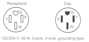
- One mast weatherhead installation, installed in accordance with Part II of Article 230, containing four continuous, insulated, color-coded feeder conductors, one of which shall be an equipment grounding conductor
- A rigid metal conduit, intermediate metal conduit, rigid polyvinyl chloride conduit, or other raceways identified for the location, from the disconnecting means in the mobile home to the underside of the mobile home, with provisions for the attachment to a suitable junction box or fitting to the raceway on the underside of the mobile home [with or without conductors as in 550.10(I)(1)]. The manufacturer shall provide written installation instructions stating the proper feeder conductor sizes for the raceway and the size of the junction box to be used.
FIGURE 550.10(C) 50-Ampere, 125/250-Volt Receptacle and Attachment Plug Cap Configurations, 3-Pole, 4-Wire, Grounding-Types, Used for Mobile Home Supply Cords and Mobile Home Parks.
550.11 Disconnecting Means and Branch-Circuit Protective Equipment.
The branch-circuit equipment shall be permitted to be combined with the disconnecting means as a single assembly. Such a combination shall be permitted to be designated as a panelboard. If a fused panelboard is used, the maximum fuse size for the mains shall be plainly marked with lettering at least 6 mm (1/4 in.) high and visible when fuses are changed.
Where plug fuses and fuseholders are used, they shall be tamper-resistant Type S, enclosed in dead-front fuse panelboards. Electrical panelboards containing circuit breakers shall also be dead-front type.
Informational Note: See 110.22 concerning identification of each disconnecting means and each service, feeder, or branch circuit at the point where it originated and the type marking needed.
(A) Disconnecting Means.
A single disconnecting means shall be provided in each mobile home consisting of a circuit breaker, or a switch and fuses and its accessories installed in a readily accessible location near the point of entrance of the supply cord or conductors into the mobile home. The main circuit breakers or fuses shall be plainly marked "Main." This equipment shall contain a solderless type of grounding connector or bar for the purposes of grounding, with sufficient terminals for all grounding conductors. The terminations of the grounded circuit conductors shall be insulated in accordance with 550.16(A). The disconnecting equipment shall have a rating not less than the calculated load. The distribution equipment, either circuit breaker or fused type, shall be located a minimum of 600 mm (24 in.) from the bottom of such equipment to the floor level of the mobile home.
Informational Note: See 550.20(B) for information on disconnecting means for branch circuits designed to energize heating or air-conditioning equipment, or both, located outside the mobile home, other than room air conditioners.
A panelboard shall be rated not less than 50 amperes and employ a 2-pole circuit breaker rated 40 amperes for a 40-ampere supply cord, or 50 amperes for a 50-ampere supply cord. A panelboard employing a disconnect switch and fuses shall be rated 60 amperes and shall employ a single 2-pole, 60-ampere fuseholder with 40- or 50-ampere main fuses for 40- or 50-ampere supply cords, respectively. The outside of the panelboard shall be plainly marked with the fuse size.
The panelboard shall be located in an accessible location but shall not be located in a bathroom or a clothes closet. A clear working space at least 750 mm (30 in.) wide and 750 mm (30 in.) in front of the panelboard shall be provided. This space shall extend from the floor to the top of the panelboard.
(B) Branch-Circuit Protective Equipment.
Branch-circuit distribution equipment shall be installed in each mobile home and shall include overcurrent protection for each branch circuit consisting of either circuit breakers or fuses.
- Not more than the circuit conductors; and
- Not more than 150 percent of the rating of a single appliance rated 13.3 amperes or more that is supplied by an individual branch circuit; but
- Not more than the overcurrent protection size and of the type marked on the air conditioner or other motor-operated appliance.
(C) Two-Pole Circuit Breakers.
Where circuit breakers are provided for branch-circuit protection, 240-volt circuits shall be protected by a 2-pole common or companion trip, or by circuit breakers with identified handle ties.
(D) Electrical Nameplates.
A metal nameplate on the outside adjacent to the feeder assembly entrance shall read as follows:
The correct ampere rating shall be marked in the blank space.
Exception: For manufactured homes, the manufacturer shall provide in its written installation instructions or in the data plate the minimum ampere rating of the feeder assembly or, where provided, the service-entrance conductors intended for connection to the manufactured home. The rating provided shall not be less than the minimum load calculated in accordance with 550.18.
550.12 Branch Circuits.
The number of branch circuits required shall be determined in accordance with 550.12(A) through (E).
(A) Lighting.
The number of branch circuits shall be based on 33 volt-amperes/m2 (3 VA/ft2) times outside dimensions of the mobile home (coupler excluded) divided by 120 volts to determine the number of 15- or 20-ampere lighting area circuits, for example,
| [550.12(A)] |
 |
(B) Small Appliances.
In kitchens, pantries, dining rooms, and breakfast rooms, two or more 20-ampere small-appliance circuits, in addition to the number of circuits required elsewhere in this section, shall be provided for all receptacle outlets required by 550.13(D) in these rooms. Such circuits shall have no other outlets.
Exception No. 1: Receptacle outlets installed solely for the electrical supply and support of an electric clock in any the rooms specified in 550.12(B) shall be permitted.
Exception No. 2: Receptacle outlets installed to provide power for supplemental equipment and lighting on gas-fired ranges, ovens, or counter-mounted cooking units shall be permitted.
Exception No. 3: A single receptacle for refrigeration equipment shall be permitted to be supplied from an individual branch circuit rated 15 amperes or greater.
Countertop receptacle outlets installed in the kitchen shall be supplied by not less than two small-appliance circuit branch circuits, either or both of which shall be permitted to supply receptacle outlets in the kitchen and other locations specified in 550.12(B).
(C) Laundry Area.
Where a laundry area is provided, a 20-ampere branch circuit shall be provided to supply the laundry receptacle outlet(s). This circuit shall have no other outlets.
(D) General Appliances.
(Including furnace, water heater, range, and central or room air conditioner, etc.). There shall be one or more circuits of adequate rating in accordance with the following:
Informational Note: See Article 440 for central air conditioning.
- The ampere rating of fixed appliances shall be not over 50 percent of the circuit rating if lighting outlets (receptacles, other than kitchen, dining area, and laundry, considered as lighting outlets) are on the same circuit.
- For fixed appliances on a circuit without lighting outlets, the sum of rated amperes shall not exceed the branch-circuit rating. Motor loads or continuous loads shall not exceed 80 percent of the branch-circuit rating.
- The rating of a single cord-and-plug-connected appliance on a circuit having no other outlets shall not exceed 80 percent of the circuit rating.
- The rating of a range branch circuit shall be based on the range demand as specified for ranges in 550.18(B)(5).
(E) Bathrooms.
Bathroom receptacle outlets shall be supplied by at least one 20-ampere branch circuit. Such circuits shall have no outlets other than as provided for in 550.13(E)(2).
550.13 Receptacle Outlets.
(A) Grounding-Type Receptacle Outlets.
All receptacle outlets shall comply with the following:
- Be of grounding type
- Be installed according to 406.4
- Except where supplying specific appliances, be 15- or 20-ampere, 125-volt, either single or multiple type, and accept parallel-blade attachment plugs
(B) Ground-Fault Circuit Interrupters (GFCI).
Ground-fault circuit-interrupter protection shall be provided as required in 210.8(A). In addition, in the following areas within a mobile or manufactured home, GFCI protection is limited to 125-volt, 15- and 20-ampere receptacles or outlets:
- Compartments accessible from outside the unit
- Bathrooms, including receptacles in luminaires
- Kitchens, where receptacles are installed to serve countertop surfaces
- Sinks, where receptacles are installed within 1.8 m (6 ft) from the top inside edge of the sink
- Dishwashers
Informational Note: See 422.5(A) for information on protection of dishwashers.
(C) Cord-Connected Fixed Appliance.
A grounding-type receptacle outlet shall be provided for each cord-connected fixed appliance installed.
(D) Receptacle Outlets Required.
Except in the bath, closet, and hallway areas, receptacle outlets shall be installed at wall spaces 600 mm (2 ft) wide or more so that no point along the floor line is more than 1.8 m (6 ft) measured horizontally from an outlet in that space. In addition, a receptacle outlet shall be installed in the following locations:
- Over or adjacent to countertops in the kitchen [at least one on each side of the sink if countertops are on each side and are 300 mm (12 in.) or over in width].
- Adjacent to the refrigerator and freestanding gas-range space. A multiple-type receptacle shall be permitted to serve as the outlet for a countertop and a refrigerator.
- At countertop spaces for built-in vanities.
- At countertop spaces under wall-mounted cabinets.
- In the wall at the nearest point to where a bar-type counter attaches to the wall.
- In the wall at the nearest point to where a fixed room divider attaches to the wall.
- In laundry areas within 1.8 m (6 ft) of the intended location of the laundry appliance(s).
- At least one receptacle outlet located outdoors and accessible at grade level and not more than 2.0 m (61/2 ft) above grade. A receptacle outlet located in a compartment accessible from the outside of the unit shall be considered an outdoor receptacle.
- At least one receptacle outlet shall be installed in bathrooms within 900 mm (36 in.) of the outside edge of each basin. The receptacle outlet shall be located above or adjacent to the basin location. This receptacle shall be in addition to any receptacle that is a part of a luminaire or appliance. The receptacle shall not be enclosed within a bathroom cabinet or vanity.
(E) Pipe Heating Cable(s) Outlet.
For the connection of pipe heating cable(s), a receptacle outlet shall be located on the underside of the unit as follows:
- Within 600 mm (2 ft) of the cold water inlet.
- Connected to an interior branch circuit, other than a small-appliance branch circuit. It shall be permitted to use a bathroom receptacle circuit for this purpose.
- On a circuit where all of the outlets are on the load side of the ground-fault circuit interrupter.
- This outlet shall not be considered as the receptacle required by 550.13(D)(8).
(F) Receptacle Outlets Not Permitted.
Receptacle outlets shall not be permitted in the following locations:
- Receptacle outlets shall not be installed within or directly over a bathtub or shower space.
- A receptacle shall not be installed in a face-up position in any countertop.
- Receptacle outlets shall not be installed above electric baseboard heaters, unless provided for in the listing or manufacturer's instructions.
(G) Receptacle Outlets Not Required.
Receptacle outlets shall not be required in the following locations:
- In the wall space occupied by built-in kitchen or wardrobe cabinets
- In the wall space behind doors that can be opened fully against a wall surface
- In room dividers of the lattice type that are less than 2.5 m (8 ft) long, not solid, and within 150 mm (6 in.) of the floor
- In the wall space afforded by bar-type counters
550.14 Luminaires and Appliances.
(A) Fasten Appliances in Transit.
Means shall be provided to securely fasten appliances when the mobile home is in transit. (See 550.16 for provisions on grounding.)
(B) Accessibility.
Every appliance shall be accessible for inspection, service, repair, or replacement without removal of permanent construction.
550.15 Wiring Methods and Materials.
Except as specifically limited in this section, the wiring methods and materials included in this Code shall be used in mobile homes. Where conductors are terminated, they shall be used with equipment listed and identified for the conductor materials.
(C) Metal-Covered and Nonmetallic Cable Protection.
Metal-covered and nonmetallic cables shall be permitted to pass through the centers of the wide side of 2 by 4 studs. However, they shall be protected where they pass through 2 by 2 studs or at other studs or frames where the cable or armor would be less than 32 mm (11/4 in.) from the inside or outside surface of the studs where the wall covering materials are in contact with the studs. Steel plates on each side of the cable, or a tube, with not less than 1.35 mm (0.053 in.) wall thickness shall be required to protect the cable. These plates or tubes shall be securely held in place.
(E) Installation Requirements.
Where a range, clothes dryer, or other appliance is connected by metal-covered cable or flexible metal conduit, a length of not less than 900 mm (3 ft) of unsupported cable or conduit shall be provided to service the appliance. The cable or flexible metal conduit shall be secured to the wall. Type NM or Type SE cable shall not be used to connect a range or dryer. This shall not prohibit the use of Type NM or Type SE cable between the branch-circuit overcurrent protective device and a junction box or range or dryer receptacle.
(F) Raceways.
Where rigid metal conduit or intermediate metal conduit is terminated at an enclosure with a locknut and bushing connection, two locknuts shall be provided, one inside and one outside of the enclosure. Rigid nonmetallic conduit, electrical nonmetallic tubing, or surface raceway shall be permitted. All cut ends of conduit and tubing shall be reamed or otherwise finished to remove rough edges.
(G) Switches.
Switches shall be rated as follows:
- For lighting circuits, switches shall be rated not less than 10 amperes, 120 to 125 volts, and in no case less than the connected load.
- Switches for motor or other loads shall comply with 404.14.
(H) Under-Chassis Wiring (Exposed to Weather).
- Where outdoor or under-chassis line-voltage (120 volts, nominal, or higher) wiring is exposed, it shall be protected by a conduit or raceway identified for use in wet locations. The conductors shall be listed for use in wet locations.
- Where wiring is exposed to physical damage, it shall be protected by a raceway, conduit, or other means.
(I) Boxes, Fittings, and Cabinets.
Boxes, fittings, and cabinets shall be securely fastened in place and shall be supported from a structural member of the home, either directly or by using a substantial brace.
Exception: Snap-in-type boxes. Boxes provided with special wall or ceiling brackets and wiling devices with integral enclosures that securely fasten to walls or ceilings and are identified for the use shall be permitted without support from a structured member or brace. The testing and approval shall include the wall and ceiling construction systems for which the boxes and devices are intended to be used.
(J) Appliance Terminal Connections.
Appliances having branch-circuit terminal connections that operate at temperatures higher than 60°C (140°F) shall have circuit conductors as described in the following:
- Branch-circuit conductors having an insulation suitable for the temperature encountered shall be permitted to be run directly to the appliance.
- Conductors having an insulation suitable for the temperature encountered shall be run from the appliance terminal connection to a readily accessible outlet box placed at least 300 mm (1 ft) from the appliance. These conductors shall be in a suitable raceway or Type AC or MC cable of at least 450 mm (18 in.) but not more than 1.8 m (6 ft) in length.
(K) Component Interconnections.
Fittings and connectors that are intended to be concealed at the time of assembly shall be listed and identified for the interconnection of building components. Such fittings and connectors shall be equal to the wiring method employed in insulation, temperature rise, and fault-current withstanding and shall be capable of enduring the vibration and shock occurring in mobile home transportation.
Informational Note: See 550.19 for interconnection of multiple section units.
550.16 Grounding.
Grounding of both electrical and nonelectrical metal parts in a mobile home shall be through connection to a grounding bus in the mobile home panelboard and shall be connected through the green-colored insulated conductor in the supply cord or the feeder wiring to the grounding bus in the service-entrance equipment located adjacent to the mobile home location. Neither the frame of the mobile home nor the frame of any appliance shall be connected to the grounded circuit conductor in the mobile home. Where the panelboard is the service equipment as permitted by 550.32(B), the neutral conductors and the equipment grounding bus shall be connected.
(A) Grounded Conductor.
(1) Insulated.
The grounded circuit conductor shall be insulated from the equipment grounding conductors and from equipment enclosures and other grounded parts. The grounded circuit conductor terminals in the panelboard and in ranges, clothes dryers, counter-mounted cooking units, and wall-mounted ovens shall be insulated from the equipment enclosure. Bonding screws, straps, or buses in the panelboard or in appliances shall be removed and discarded. Where the panelboard is the service equipment as permitted by 550.32(B), the neutral conductors and the equipment grounding bus shall be connected.
(B) Equipment Grounding Means.
(1) Supply Cord or Permanent Feeder.
The green-colored insulated grounding wire in the supply cord or permanent feeder wiring shall be connected to the grounding bus in the panelboard or disconnecting means.
(2) Electrical System.
In the electrical system, all exposed metal parts, enclosures, frames, luminaire canopies, and so forth, shall be effectively bonded to the grounding terminal or enclosure of the panelboard.
(3) Cord-Connected Appliances.
Cord-connected appliances, such as washing machines, clothes dryers, and refrigerators, and the electrical system of gas ranges and so forth, shall be grounded by means of a cord with an equipment grounding conductor and grounding-type attachment plug.
(C) Bonding of Non-Current-Carrying Metal Parts.
(1) Exposed Non-Current-Carrying Metal Parts.
All exposed non—current-carrying metal parts that are likely to become energized shall be effectively bonded to the grounding terminal or enclosure of the panelboard. A bonding conductor shall be connected between the panelboard and an accessible terminal on the chassis. Chassis of multiple mobile home sections shall be bonded together with a solid copper, 8 AWG minimum, insulated or bare, bonding conductor with terminations in accordance with 250.8 and 250.12.
(2) Grounding Terminals.
Grounding terminals shall be of the solderless type and listed as pressure-terminal connectors recognized for the wire size used. The bonding conductor shall be solid or stranded, insulated or bare, and shall be 8 AWG copper minimum, or equivalent. The bonding conductor shall be routed so as not to be exposed to physical damage.
(3) Metallic Piping and Ducts.
Metallic gas, water, and waste pipes and metallic air-circulating ducts shall be considered bonded if they are connected to the terminal on the chassis [see 550.16(C)(1)] by clamps, solderless connectors, or by suitable grounding-type straps.
(4) Metallic Roof and Exterior Coverings.
Any metallic roof and exterior covering shall be considered bonded if the following conditions are met:
- The metal panels overlap one another and are securely attached to the wood or metal frame parts by metallic fasteners.
- The lower panel of the metallic exterior covering is secured by metallic fasteners at a cross member of the chassis by two metal straps per mobile home unit or section at opposite ends.
The bonding strap material shall be a minimum of 100 mm (4 in.) in width of material equivalent to the skin or a material of equal or better electrical conductivity. The straps shall be fastened with paint-penetrating fittings such as screws and star-washers or equivalent.
550.17 Testing.
(A) Dielectric Strength Test.
The wiring of each mobile home shall be subjected to a 1-minute, 900-volt, dielectric strength test (with all switches closed) between live parts (including neutral conductor) and the mobile home ground. Alternatively, the test shall be permitted to be performed at 1080 volts for 1 second. This test shall be performed after branch circuits are complete and after luminaires or appliances are installed.
Exception: Listed luminaires or appliances shall not be required to withstand the dielectric strength test.
(B) Continuity and Operational Tests and Polarity Checks.
Each mobile home shall be subjected to all of the following:
- An electrical continuity test to ensure that all exposed electrically conductive parts are properly bonded
- An electrical operational test to demonstrate that all equipment, except water heaters and electric furnaces, is connected and in working order
- Electrical polarity checks of permanently wired equipment and receptacle outlets to determine that connections have been properly made
550.18 Calculations.
The following method shall be employed in calculating the supply-cord and distribution-panelboard load for each feeder assembly for each mobile home in lieu of the procedure shown in Article 220 and shall be based on a 3-wire, 120/240-volt supply with 120-volt loads balanced between the two ungrounded conductors of the 3-wire system.
(A) Lighting, Small-Appliance, and Laundry Load.
(1) Lighting Volt-Amperes.
Length times width of mobile home floor (outside dimensions) times 33 volt-amperes/m2 (3 VA/ft2)- for example, length × width × 3 = lighting voltamperes.
(2) Small-Appliance Volt-Amperes.
Number of circuits times 1500 volt-amperes for each 20-ampere appliance receptacle circuit - for example, number of circuits × 1500 = small-appliance volt-amperes.
(3) Laundry Area Circuit Volt-Amperes.
1500 volt-amperes.
(4) Total Volt-Amperes.
Lighting volt-amperes plus small-appliance volt-amperes plus laundry area volt-amperes equals total volt-amperes.
(5) Net Volt-Amperes.
First 3000 total volt-amperes at 100 percent plus remainder at 35 percent equals volt-amperes to be divided by 240 volts to obtain current (amperes) per leg.
(B) Total Load for Determining Power Supply.
Total load for determining power supply is the sum of the following:
- Lighting and small-appliance load as calculated in 550.18(A)(5).
- Nameplate amperes for motors and heater loads (exhaust fans, air conditioners, electric, gas, or oil heating). Omit smaller of the heating and cooling loads, except include blower motor if used as air-conditioner evaporator motor. Where an air conditioner is not installed and a 40-ampere power-supply cord is provided, allow 15 amperes per leg for air conditioning.
- Twenty-five percent of current of largest motor in 550.18(B)(2).
- Total of nameplate amperes for waste disposer, dishwasher, water heater, clothes dryer, wall-mounted oven, cooking units. Where the number of these appliances exceeds three, use 75 percent of total.
- Derive amperes for freestanding range (as distinguished from separate ovens and cooking units) by dividing the following values by 240 volts as shown in Table 550.18(B).
- If outlets or circuits are provided for other than factory-installed appliances, include the anticipated load.
Informational Note: See Informative Annex D, Example D11, for an illustration of the application of this calculation.
(C) Optional Method of Calculation for Lighting and Appliance Load.
Table 550.18(B) Freestanding Range Load.
| Nameplate Rating (watts) | Use (volt-amperes) |
|---|---|
| 0—10,000 | 80 percent of rating |
| Over 10,000—12,500 | 8,000 |
| Over 12,500—13,500 | 8,400 |
| Over 13,500—14,500 | 8,800 |
| Over 14,500—15,500 | 9,200 |
| Over 15,500—16,500 | 9,600 |
| Over 16,500—17,500 | 10,000 |
550.19 Interconnection of Multiple-Section Mobile or Manufactured Home Units.
(A) Wiring Methods.
Approved and listed fixed-type wiring methods shall be used to join portions of a circuit that must be electrically joined and are located in adjacent sections after the home is installed on its support foundation. The circuit's junction shall be accessible for disassembly when the home is prepared for relocation.
Informational Note: See 550.15 (K) for component interconnections.
(B) Disconnecting Means.
Expandable or multiunit manufactured homes, not having permanently installed feeders, that are to be moved from one location to another shall be permitted to have disconnecting means with branch-circuit protective equipment in each unit when so located that after assembly or joining together of units, the requirements of 550.10 will be met.
550.20 Outdoor Outlets, Luminaires, Air-Cooling Equipment, and So Forth.
(A) Listed for Outdoor Use.
Outdoor luminaires and equipment shall be listed for wet locations or outdoor use. Outdoor receptacles shall comply with 406.9. Where located on the underside of the home or located under roof extensions or similarly protected locations, outdoor luminaires and equipment shall be listed for use in damp locations.
(B) Outside Heating Equipment, Air-Conditioning Equipment, or Both.
A mobile home provided with a branch circuit designed to energize outside heating equipment, air-conditioning equipment, or both, located outside the mobile home, other than room air conditioners, shall have such branch-circuit conductors terminate in a listed outlet box, or disconnecting means, located on the outside of the mobile home. A label shall be permanently affixed adjacent to the outlet box and shall contain the following information:
THIS CONNECTION IS FOR HEATING
AND/OR AIR-CONDITIONING EQUIPMENT.
THE BRANCH CIRCUIT IS RATED AT NOT MORE THAN
_______ AMPERES, AT ______ VOLTS, 60 HERTZ,
CONDUCTOR AMPACITY.
A DISCONNECTING MEANS SHALL BE LOCATED
WITHIN SIGHT OF THE EQUIPMENT.
AND/OR AIR-CONDITIONING EQUIPMENT.
THE BRANCH CIRCUIT IS RATED AT NOT MORE THAN
_______ AMPERES, AT ______ VOLTS, 60 HERTZ,
CONDUCTOR AMPACITY.
A DISCONNECTING MEANS SHALL BE LOCATED
WITHIN SIGHT OF THE EQUIPMENT.
The correct voltage and ampere rating shall be given. The tag shall be not less than 0.51 mm (0.020 in.) thick etched brass, stainless steel, anodized or alclad aluminum, or equivalent. The tag shall not be less than 75 mm by 45 mm (3 in. by 13/4 in.) minimum size.
550.25 Arc-Fault Circuit-Interrupter Protection.
All 120-volt, single-phase, 15- and 20-ampere branch circuits supplying outlets or devices installed in mobile homes and manufactured homes shall comply with 210.12
550.30 Distribution System.
The mobile home park secondary electrical distribution system to mobile home lots shall be single-phase, 120/240 volts, nominal.
550.31 Allowable Demand Factors.
Park electrical wiring systems shall be calculated (at 120/240 volts) on the larger of the following:
- 16,000 volt-amperes for each mobile home lot
- The load calculated in accordance with 550.18 for the largest typical mobile home that each lot will accept
It shall be permissible to calculate the feeder or service load in accordance with Table 550.31. No demand factor shall be allowed for any other load, except as provided in this Code.
Table 550.31 Demand Factors for Services and Feeders.
| Number of Mobile Homes | Demand Factor (%) |
|---|---|
| 1 | 100 |
| 2 | 55 |
| 3 | 44 |
| 4 | 39 |
| 5 | 33 |
| 6 | 29 |
| 7—9 | 28 |
| 10—12 | 27 |
| 13—15 | 26 |
| 16—21 | 25 |
| 22—40 | 24 |
| 41—60 | 23 |
| 61 and over | 22 |
550.32 Service Equipment.
(A) Mobile Home Service Equipment.
The mobile home service equipment shall not be mounted in or on the mobile home. The service equipment shall be rated not less than that required in accordance with 550.32(C), mounted in a readily accessible outdoor location, and within sight from the mobile home it serves. The mobile home service disconnect shall be permitted to be used as the emergency disconnect in accordance with 230.85.
(B) Manufactured Home Service Equipment.
The manufactured home service equipment shall be permitted to be installed in or on a manufactured home, provided that all of the following conditions are met:
- The manufacturer shall include in its written installation instructions information indicating that the home shall be secured in place by an anchoring system or installed on and secured to a permanent foundation.
- The installation of the service shall comply with Part I through Part VII of Article 230.
- Means shall be provided for the connection of a grounding electrode conductor to the service equipment and routing it outside the structure.
- Bonding and grounding of the service shall be in accordance with Part I through Part V of Article 250.
- The manufacturer shall include in its written installation instructions one method of grounding the service equipment at the installation site. The instructions shall clearly state that other methods of grounding are found in Article 250.
- The minimum size grounding electrode conductor shall be specified in the instructions.
- A warning label shall be mounted on or adjacent to the service equipment. The label shall meet the requirements in 110.21(B) and shall state the following:
WARNING
DO NOT PROVIDE ELECTRICAL POWER UNTIL THE GROUNDING ELECTRODE(S)
IS INSTALLED AND CONNECTED (SEE INSTALLATION INSTRUCTIONS).
DO NOT PROVIDE ELECTRICAL POWER UNTIL THE GROUNDING ELECTRODE(S)
IS INSTALLED AND CONNECTED (SEE INSTALLATION INSTRUCTIONS).
Where the service equipment is not installed in or on the unit, the installation shall comply with the other requirements of this section.
(C) Rating.
Mobile home service equipment shall be rated at not less than 100 amperes at 120/240 volts, and provisions shall be made for connecting a mobile home feeder assembly by a permanent wiring method. Power outlets used as mobile home service equipment shall also be permitted to contain receptacles rated up to 50 amperes with appropriate overcurrent protection. Fifty-ampere receptacles shall conform to the configuration shown in Figure 550.10(C).
Informational Note: See ANSI/NEMA WD 6-2016, Wiring Devices - Dimensional Specifications, Figure 14-50, for complete details of the 50-ampere plug and receptacle configuration.
(D) Additional Outside Electrical Equipment.
Means for connecting a mobile home accessory building or structure or additional electrical equipment located outside a mobile home by a fixed wiring method shall be provided in either the mobile home service equipment or the local external disconnecting means permitted in 550.32(A).
(E) Additional Receptacles.
Receptacles located outside a mobile or manufactured home shall be provided with ground-fault circuit-interrupter protection as specified by 210.8(A). Where receptacles provide power to a mobile or manufactured home in accordance with 550.10, ground-fault circuit-interrupter protection shall not be required.
(F) Mounting Height.
Outdoor mobile home disconnecting means shall be installed so the bottom of the enclosure containing the disconnecting means is not less than 600 mm (2 ft) above finished grade or working platform. The disconnecting means shall be installed so that the center of the grip of the operating handle, when in the highest position, is not more than 2.0 m (6 ft 7 in.) above the finished grade or working platform.
(G) Marking.
Where a 125/250-volt receptacle is used in mobile home service equipment, the service equipment shall be marked as follows:
TURN DISCONNECTING SWITCH OR
CIRCUIT BREAKER OFF BEFORE INSERTING
OR REMOVING PLUG. PLUG MUST BE FULLY
INSERTED OR REMOVED.
CIRCUIT BREAKER OFF BEFORE INSERTING
OR REMOVING PLUG. PLUG MUST BE FULLY
INSERTED OR REMOVED.
The marking shall be located on the service equipment adjacent to the receptacle outlet.
550.33 Feeder.
(A) Feeder Equipment.
The feeder assembly, including the disconnecting means, shall not be mounted in or on the mobile home. A manufactured home feeder disconnecting means shall be permitted to be installed in or on the manufactured home in accordance with the requirements of 550.32(B). The feeder equipment shall be rated not less than that required in 550.32(C), mounted in a readily accessible outdoor location, and within sight from the mobile home or manufactured home it serves. Grounding of the disconnecting means shall be in accordance with 250.32.
(B) Feeder Conductors.
Feeder conductors shall comply with the following:
- Feeder conductors shall consist of either a listed cord, factory installed in accordance with 550.10(B), or a permanently installed feeder consisting of four insulated, color-coded conductors that shall be identified by the factory or field marking of the conductors in compliance with 310.6. Equipment grounding conductors shall not be identified by stripping the insulation.
- Feeder conductors shall be installed in compliance with 250.32(B).
Exception: An existing feeder installed without an equipment grounding conductor shall be permitted to comply with 250.32(B)(1) Exception No. 1.
(C) Feeder Capacity.
Mobile home and manufactured home feeder circuit conductors shall have a capacity not less than the loads supplied, shall have an ampacity of not less than 100 amperes, and shall be permitted to be sized in accordance with 310.12.
Article 551
Recreational Vehicles and Recreational Vehicle Parks
551.1 Scope.
This article covers the electrical conductors and equipment other than low-voltage and automotive vehicle circuits or extensions thereof, installed within or on recreational vehicles, the conductors that connect recreational vehicles to a supply of electricity, and the installation of equipment and devices related to electrical installations within a recreational vehicle park.
Informational Note: See NFPA 1192-2021, Standard on Recreational Vehicles, and ANSI/RVIA LV-2020, Standard for Low Voltage Systems in Conversion and Recreational Vehicles, for information on low-voltage systems.
551.3 Electrical Datum Plane Distances.
The electrical datum plane distance(s) is determined by the normal high water level and encompasses the areas subject to tidal movement and areas in which the water level is affected by the conditions such as climate (rain or snowfall) or by human intervention (the opening and closing of dams or floodgates). The distance does not consider extremes due to natural or manmade disasters.
(A) Areas Subject to Tidal Fluctuations.
In land areas subject to tidal fluctuation, the electrical datum plane shall be a horizontal plane that is 606 mm (2 ft) above the highest high tide level for the area occurring under normal circumstances.
(B) Areas Not Subject to Tidal Fluctuations.
In land areas not subject to tidal fluctuation, the electrical datum plane shall be a horizontal plane that is 606 mm (2 ft) above the normal high water level for the area occurring under normal circumstances.
551.4 General Requirements.
(A) Not Covered.
A recreational vehicle not used for the purposes as defined in 551.2 shall not be required to meet the requirements of Part IV pertaining to the number or capacity of circuits required. It shall, however, meet all other applicable requirements of this article if the recreational vehicle is provided with an electrical installation intended to be energized from a 120-volt, 208Y/120-volt, or 120/240-volt, nominal, ac power-supply system.
(B) Systems.
This article covers combination electrical systems, generator installations, and 120-volt, 208Y/120-volt, or 120/240-volt, nominal, systems.
Informational Note: See NFPA 1192-2021, Standard on Recreational Vehicles, and ANSI/RVIA 12V-2020, Standard for Low Voltage Systems in Conversion and Recreational Vehicles, for information on low-voltage systems.
(C) Labels.
Labels required by Article 551 shall be made of etched, metal-stamped, or embossed brass; stainless steel; plastic laminates not less than 0.13 mm (0.005 in.) thick; or anodized or alclad aluminum not less than 0.5 mm (0.020 in.) thick or the equivalent.
Informational Note: See ANSI Z535.4-2011, Product Safety Signs and Labels, for guidance on other label criteria used in the recreational vehicle industry.
551.20 Combination Electrical Systems.
(A) General.
Vehicle wiring suitable for connection to a battery or dc supply source shall be permitted to be connected to a 120-volt source, provided the entire wiring system and equipment are rated and installed in full conformity with Parts I, II, III, IV, and V requirements of this article covering 120-volt electrical systems. Circuits fed from ac transformers shall not supply dc appliances.
(B) Voltage Converters (120-Volt Alternating Current to Low-Voltage Direct Current).
The 120-volt ac side of the voltage converter shall be wired in full conformity with the requirements of Parts I, II, and IV of this article for 120-volt electrical systems.
Exception: Converters supplied as an integral part of a listed appliance shall not be subject to 551.20(B).
All converters and transformers shall be listed for use in recreational vehicles and designed or equipped to provide overtemperature protection. To determine the converter rating, the following percentages shall be applied to the total connected load, including average battery-charging rate, of all 12-volt equipment:
The first 20 amperes of load at 100 percent plus
The second 20 amperes of load at 50 percent plus
All load above 40 amperes at 25 percent
Exception: A low-voltage appliance that is controlled by a momentary switch (normally open) that has no means for holding in the closed position or refrigerators with a 120-volt function shall not be considered as a connected load when determining the required converter rating. Momentarily energized appliances shall be limited to those used to prepare the vehicle for occupancy or travel.
(D) Dual-Voltage Fixtures, Including Luminaires or Appliances.
Fixtures, including luminaires, or appliances having both 120-volt and low-voltage connections shall be listed for dual voltage.
(E) Autotransformers.
Autotransformers shall not be used.
(F) Receptacles and Plug Caps.
Where a recreational vehicle is equipped with an ac system, a low-voltage system, or both, receptacles and plug caps of the low-voltage system shall differ in configuration from those of the ac system. Where a vehicle equipped with a battery or other low-voltage system has an external connection for low-voltage power, the connector shall have a configuration that will not accept ac power.
551.30 Generator Installations.
(A) Mounting.
Generators shall be mounted in such a manner as to be effectively bonded to the recreational vehicle chassis. The connection of the electrical system produced by the generator shall provide an effective ground-fault return path when operational.
(B) Generator Protection.
Equipment shall be installed to ensure that the current-carrying conductors from the engine generator and from an outside source are not connected to a vehicle circuit at the same time. Automatic transfer switches in such applications shall be listed for use in one of the following:
Receptacles used as disconnecting means shall be accessible (as applied to wiring methods) and capable of interrupting their rated current without hazard to the operator.
(C) Installation of Storage Batteries and Generators.
Storage batteries and internal-combustion-driven generator units (subject to the provisions of this Code) shall be secured in place to avoid displacement from vibration and road shock.
(D) Ventilation of Generator Compartments.
Compartments accommodating internal-combustion-driven generator units shall be provided with ventilation in accordance with instructions provided by the manufacturer of the generator unit.
Informational Note: See NFPA 1192-2021, Standard on Recreational Vehicles, for generator compartment construction requirements.
(E) Supply Conductors.
The supply conductors from the engine generator to the first termination on the vehicle shall be of the stranded type and be installed in listed flexible conduit or listed liquidtight flexible conduit. The point of first termination shall be in one of the following:
- Panelboard
- Junction box with a blank cover
- Junction box with a receptacle
- Enclosed transfer switch
- Receptacle assembly listed in conjunction with the generator
The panelboard, enclosed transfer switch, or junction box with a receptacle shall be installed within 450 mm (18 in.) of the point of entry of the supply conductors into the vehicle. A junction box with a blank cover shall be mounted on the compartment wall inside or outside the compartment; to any part of the generator-supporting structure (but not to the generator); to the vehicle floor on the outside of the vehicle; or within 450 mm (18 in.) of the point of entry of the supply conductors into the vehicle. A receptacle assembly listed in conjunction with the generator shall be mounted in accordance with its listing.
551.31 Multiple Supply Source.
(A) Multiple Supply Sources.
Where a multiple supply system consisting of an alternate power source and a power-supply cord is installed, the feeder from the alternate power source shall be protected by an overcurrent protective device. Installation shall be in accordance with 551.30(A), 551.30(B), and 551.40.
(B) Multiple Supply Sources Capacity.
The multiple supply sources shall not be required to be of the same capacity.
(C) Alternate Power Sources Exceeding 30 Amperes.
If an alternate power source exceeds 30 amperes, 120 volts, nominal, it shall be permissible to wire it as a 120-volt, nominal, system, a 208Y/120-volt, nominal, system, or a 120/240-volt, nominal, system, provided an overcurrent protective device of the proper rating is installed in the feeder.
(D) Feeder Assembly Not Less Than 30 Amperes.
The external feeder assembly shall be permitted to be less than the calculated load but not less than 30 amperes and shall have overcurrent protection not greater than the capacity of the external feeder assembly.
551.32 Other Sources.
Other sources of ac power, such as inverters, motor generators, or engine generators, shall be listed for use in recreational vehicles and shall be installed in accordance with the terms of the listing. Other sources of ac power shall be wired in full conformity with the requirements in Parts I, II, III, IV, and V of this article covering 120-volt electrical systems.
551.33 Alternate Source Restrictions.
Transfer equipment, if not integral with the listed power source, shall be installed to ensure that the current-carrying conductors from other sources of ac power and from an outside source are not connected to the vehicle circuit at the same time. Automatic transfer switches in such applications shall be listed for use in one of the following:
551.40 120-Volt or 120/240-Volt, Nominal, Systems.
(A) General Requirements.
The electrical equipment and material of recreational vehicles indicated for connection to a wiring system rated 120 volts, nominal, 2-wire with equipment grounding conductor, or a wiring system rated 120/240 volts, nominal, 3-wire with equipment grounding conductor, shall be listed and installed in accordance with Parts I, II, III, IV, and V of this article. Electrical equipment connected line-to-line shall have a nominal voltage rating of 208-230 volts.
(B) Materials and Equipment.
Electrical materials, devices, appliances, fittings, and other equipment installed in, intended for use in, or attached to the recreational vehicle shall be listed. All products shall be used only in the manner in which they have been tested and found suitable for the intended use.
(C) Ground-Fault Circuit-Interrupter Protection.
The internal wiring of a recreational vehicle having only one 15- or 20-ampere branch circuit as permitted in 551.42(A) and (B) shall have ground-fault circuit-interrupter protection for personnel. The ground-fault circuit interrupter shall be installed at the point where the power supply assembly terminates within the recreational vehicle. Where a separable cord set is not employed, the ground-fault circuit interrupter shall be permitted to be an integral part of the attachment plug of the feeder assembly. The ground-fault circuit interrupter shall provide protection also under the conditions of an open grounded circuit conductor, interchanged circuit conductors, or both.
(D) Loss of Ground Device.
Each recreational vehicle shall have a listed grounding monitor interrupter permanently installed between the feeder assembly connection to the vehicle and before either a transfer switch if installed or the panelboard. This requirement shall become effective January 1, 2026.
551.41 Receptacle Outlets Required.
(A) Spacing.
Receptacle outlets shall be installed at wall spaces 600 mm (2 ft) wide or more so that no point along the floor line is more than 1.8 m (6 ft), measured horizontally, from an outlet in that space.
Exception No. 1: Bath and hallway areas shall not be required to comply with 551.41(A).
Exception No. 2: Wall spaces occupied by kitchen cabinets, wardrobe cabinets, built-in furniture, behind doors that can open fully against a wall surface, or similar facilities shall not be required to comply with 551.41(A).
Exception No. 3: Wall spaces in the special transportation area of a recreational vehicle designed to transport internal combustion vehicles shall not be required to comply with 551.41(A).
(B) Location.
Receptacle outlets shall be installed as follows:
- Adjacent to countertops in the kitchen [at least one on each side of the sink if countertops are on each side and are 300 mm (12 in.) or over in width and depth].
- Adjacent to the refrigerator and gas range space, except where a gas-fired refrigerator or cooking appliance, requiring no external electrical connection, is factory installed.
- Adjacent to countertop spaces of 300 mm (12 in.) or more in width and depth that cannot be reached from a receptacle required in 551.41(B)(1) by a cord of 1.8 m (6 ft) without crossing a traffic area, cooking appliance, or sink.
- Rooftop decks that are accessible from inside the recreational vehicle shall have at least one receptacle installed within the perimeter of the rooftop deck. The receptacle shall not be located more than 1.2 m (4 ft) above the balcony, deck, or porch surface. The receptacle shall comply with the requirements of 406.9(B) for wet locations.
- A special transportation area of recreational vehicles designed to transport internal combustion engine vehicles shall have at least one receptacle installed.
(C) Ground-Fault Circuit-Interrupter Protection.
Where provided, each 125-volt, single-phase, 15- or 20-ampere receptacle outlet shall have ground-fault circuit-interrupter protection for personnel in the following locations:
- Adjacent to a bathroom lavatory
- Where the receptacles are installed to serve the countertop surfaces and are within 1.8 m (6 ft) of any lavatory or sinkException No. 1: Receptacles installed for appliances in dedicated spaces, such as for disposals, refrigerators, and freezers shall not require ground-fault circuit-interrupter protection.Exception No. 2: Single receptacles for interior connections of expandable room sections shall not require ground-fault circuit-interrupter protection.Exception No. 3: De-energized receptacles that are within 1.8 m (6 ft) of any sink or lavatory due to the retraction of the expandable room section shall not require ground-fault circuit-interrupter protection.
- In the area occupied by a toilet, shower, tub, or any combination thereof
- On the exterior of the vehicleException: Receptacles that are located inside of an access panel that is installed on the exterior of the vehicle to supply power for an installed appliance shall not be required to have ground-fault circuit-interrupter protection.
- In the special transportation area of a recreational vehicle that is separated from the living area by a wall
The receptacle outlet shall be permitted in a listed luminaire. A receptacle outlet shall not be installed in a tub or combination tub—shower compartment.
(D) Face-Up Position.
A receptacle shall not be installed in a face-up position in any countertop or similar horizontal surface.
551.42 Branch Circuits Required.
Each recreational vehicle containing an ac electrical system shall contain one of the circuit arrangements in 551.42(A) through (D).
(A) One 15-Ampere Circuit.
One 15-ampere circuit to supply lights, receptacle outlets, and fixed appliances. Such recreational vehicles shall be equipped with one 15-ampere switch and fuse or one 15-ampere circuit breaker.
(B) One 20-Ampere Circuit.
One 20-ampere circuit to supply lights, receptacle outlets, and fixed appliances. Such recreational vehicles shall be equipped with one 20-ampere switch and fuse or one 20-ampere circuit breaker.
(C) Two to Five 15- or 20-Ampere Circuits.
Two to five 15- or 20-ampere circuits to supply lights, receptacle outlets, and fixed appliances shall be permitted. Such recreational vehicles shall be permitted to be equipped with panelboards rated 120 volts maximum or 120/240 volts maximum and listed for 30-ampere application supplied by the appropriate feeder assemblies. Not more than two 120-volt thermostatically controlled appliances shall be installed in such systems unless appliance isolation switching, energy management systems, or similar methods are used.
Exception No. 1: Additional 15- or 20-ampere circuits shall be permitted where a listed energy management system rated at 30-amperes maximum is employed within the system.
Exception No. 2: Six 15- or 20-ampere circuits shall be permitted without employing an energy management system, provided that the added sixth circuit serves only the power converter, and the combined load of all six circuits does not exceed the allowable load that was designed for use by the original five circuits.
Informational Note: See 210.23(B) for permissible loads. See 551.45(C) for main disconnect and overcurrent protection requirements.
(D) More Than Five Circuits Without a Listed Energy Management System.
A 50-ampere, 120/208-240-volt feeder assembly and a minimum 50-ampere-rated panelboard shall be used where six or more circuits are employed. The load distribution shall ensure a reasonable current balance between phases.
551.43 Branch-Circuit Protection.
(A) Rating.
The branch-circuit overcurrent devices shall be rated as follows:
- Not more than the circuit conductors, and
- Not more than 150 percent of the rating of a single appliance rated 13.3 amperes or more and supplied by an individual branch circuit, but
- Not more than the overcurrent protection size marked on an air conditioner or other motor-operated appliances
(B) Protection for Smaller Conductors.
A 20-ampere fuse or circuit breaker shall be permitted for protection for fixtures, including luminaires, leads, cords, or small appliances, and 14 AWG tap conductors, not over 1.8 m (6 ft) long for recessed luminaires.
(C) Fifteen-Ampere Receptacles Considered Protected by 20 Amperes.
If more than one receptacle or load is on a branch circuit, 15-ampere receptacles shall be permitted to be protected by a 20-ampere fuse or circuit breaker.
551.44 Feeder Assembly.
Each recreational vehicle shall have only one of the main feeder assemblies covered in 551.44(A) through (D).
(A) Fifteen-Ampere Main Feeder Assembly.
Recreational vehicles wired in accordance with 551.42(A) shall use a listed 15-ampere or larger main feeder assembly.
(B) Twenty-Ampere Main Feeder Assembly.
Recreational vehicles wired in accordance with 551.42(B) shall use a listed 20-ampere or larger main feeder assembly.
(C) Thirty-Ampere Main Feeder Assembly.
Recreational vehicles wired in accordance with 551.42(C) shall use a listed 30-ampere or larger main feeder assembly.
(D) Fifty-Ampere Feeder Assembly.
Recreational vehicles wired in accordance with 551.42(D) shall use a listed 50-ampere, 120/208-240-volt main feeder assembly.
551.45 Panelboard.
(A) Listed and Appropriately Rated.
A listed and appropriately rated panelboard or other equipment specifically listed for this purpose shall be used. The grounded conductor termination bar shall be insulated from the enclosure as provided in 551.54(C). An equipment grounding terminal bar shall be attached inside the enclosure of the panelboard.
(B) Location.
The panelboard shall be installed in a readily accessible location with the RV in the setup mode. Working clearance for the panelboard with the RV in the setup mode shall be not less than 600 mm (24 in.) wide and 750 mm (30 in.) deep.
Exception No. 1: Where the panelboard cover is exposed to the inside aisle space, one of the working clearance dimensions shall be permitted to be reduced to a minimum of 550 mm (22 in.). A panelboard is considered exposed where the panelboard cover is within 50 mm (2 in.) of the aisle's finished surface or not more than 25 mm (1 in.) from the backside of doors that enclose the space.
Exception No. 2: Compartment doors used for access to a generator shall be permitted to be equipped with a locking system.
(C) Dead-Front Type.
The panelboard shall be of the dead-front type and shall consist of one or more circuit breakers or Type S fuseholders. A main disconnecting means shall be provided where fuses are used or where more than two circuit breakers are employed. A main overcurrent protective device not exceeding the feeder assembly rating shall be provided where more than two branch circuits are employed.
551.46 Means for Connecting to Power Supply.
(A) Assembly.
The feeder assembly or assemblies shall be factory supplied or factory installed and be of one of the ty pes specified herein.
(1) Separable.
Where a separable feeder assembly consisting of a cord with a female connector and molded attachment plug cap is provided, the vehicle shall be equipped with a permanently mounted, flanged surface inlet (male, recessed-type motor-base attachment plug) wired directly to the panelboard by an approved wiring method. The attachment plug cap shall be of a listed type.
(2) Permanently Connected.
Each feeder assembly shall be connected directly to the terminals of the panelboard or conductors within a junction box and provided with means to prevent strain from being transmitted to the terminals. The ampacity of the conductors between each junction box and the terminals of each panelboard shall be at least equal to the ampacity of the power-supply cord. The supply end of the assembly shall be equipped with an attachment plug of the type described in 551.46(C). Where the cord passes through the walls or floors, it shall be protected by means of conduit and bushings or equivalent. The cord assembly shall have permanent provisions for protection against corrosion and mechanical damage while the vehicle is in transit and while the cord assembly is being stored or removed for use.
(B) Cord.
The cord exposed usable length shall be measured from the point of entrance to the recreational vehicle or the face of the flanged surface inlet (motor-base attachment plug) to the face of the attachment plug at the supply end.
The cord exposed usable length, measured to the point of entry on the vehicle exterior, shall be a minimum of 7.5 m (25 ft) where the point of entrance is at the side of the vehicle or shall be a minimum 9.0 m (30 ft) where the point of entrance is at the rear of the vehicle.
Where the cord entrance into the vehicle is more than 900 mm (3 ft) above the ground, the minimum cord lengths above shall be increased by the vertical distance of the cord entrance heights above 900 mm (3 ft).
Informational Note: See 551.46(E) for location of point of entrance of a power-supply assembly on the recreational vehicle exterior.
(C) Attachment Plugs.
(1) Units With One 15-Ampere Branch Circuit.
Recreational vehicles having only one 15-ampere branch circuit as permitted by 551.42(A) shall have an attachment plug that shall be 2-pole, 3-wire grounding type, rated 15 amperes, 125 volts, conforming to the configuration shown in Figure 551.46(C)(1).
Informational Note: See ANSI/ NEMA WD 6-2016, Wiring Devices - Dimensional Specifications, Figure 5.15, for complete details of this configuration.
(2) Units With One 20-Ampere Branch Circuit.
Recreational vehicles having only one 20-ampere branch circuit as permitted in 551.42(B) shall have an attachment plug that shall be 2-pole, 3-wire grounding type, rated 20 amperes, 125 volts, conforming to the configuration shown in Figure 551.46(C)(1).
Informational Note: See ANSI/NEMA WD 6-2016, Wiring Devices - Dimensional Specifications, Figure 5.20, for complete details of this configuration.
(3) Units With Two to Five 15- or 20-Ampere Branch Circuits.
Recreational vehicles wired in accordance with 551.42(C) shall have an attachment plug that shall be 2-pole, 3-wire grounding type, rated 30 amperes, 125 volts, conforming to the configuration shown in Figure 551.46(C)(1) intended for use with units rated at 30 amperes, 125 volts.
Informational Note: See ANSI/NEMA WD 6-2016, Wiring Devices - Dimensional Specifications, Figure TT, for complete details of this configuration.
(4) Units With 50-Ampere Power-Supply Assembly.
Recreational vehicles having a power-supply assembly rated 50 amperes as permitted by 551.42(D) shall have a 3-pole, 4-wire grounding-type attachment plug rated 50 amperes, 125/250 volts, conforming to the configuration shown in Figure 551.46(C)(1).
Informational Note: See ANSI/NEMA WD 6-2016, Wiring Devices - Dimensional Specifications, Figure 14.50, for complete details of this configuration.
(D) Labeling at Electrical Entrance.
Each recreational vehicle shall have a safety label with the signal word WARNING in minimum 6-mm (1/4-in. ) high letters and body text in minimum 3-mm (1/8-in.) high letters on a contrasting background. The safety label shall be affixed to the exterior skin, at or near the point of entrance of the power-supply cord(s), and shall read, using one of the following warnings, as appropriate:
WARNING
THIS CONNECTION IS FOR 110—125-VOLT AC,
60 HZ, _____ AMPERE SUPPLY.
DO NOT EXCEED CIRCUIT RATING.
EXCEEDING THE CIRCUIT RATING CAN CAUSE A
FIRE AND RESULT IN DEATH OR SERIOUS INJURY.
THIS CONNECTION IS FOR 110—125-VOLT AC,
60 HZ, _____ AMPERE SUPPLY.
DO NOT EXCEED CIRCUIT RATING.
EXCEEDING THE CIRCUIT RATING CAN CAUSE A
FIRE AND RESULT IN DEATH OR SERIOUS INJURY.
or
WARNING
THIS CONNECTION IS FOR 208Y/120-VOLT
120/240-VOLT AC, 3-POLE, 4-WIRE, 60 HZ, ________ AMPERE
SUPPLY.
THIS CONNECTION IS FOR 208Y/120-VOLT
120/240-VOLT AC, 3-POLE, 4-WIRE, 60 HZ, ________ AMPERE
SUPPLY.
DO NOT EXCEED CIRCUIT RATING.
EXCEEDING THE CIRCUIT RATING CAN CAUSE A
FIRE AND RESULT IN DEATH OR SERIOUS INJURY.
EXCEEDING THE CIRCUIT RATING CAN CAUSE A
FIRE AND RESULT IN DEATH OR SERIOUS INJURY.
The correct ampere rating shall be marked in the blank space.
(E) Location.
The point of entrance of a power-supply assembly shall be located within 4.5 m (15 ft) of the rear, on the left (road) side or at the rear, left of the longitudinal center of the vehicle, within 450 mm (18 in.) of the outside wall. 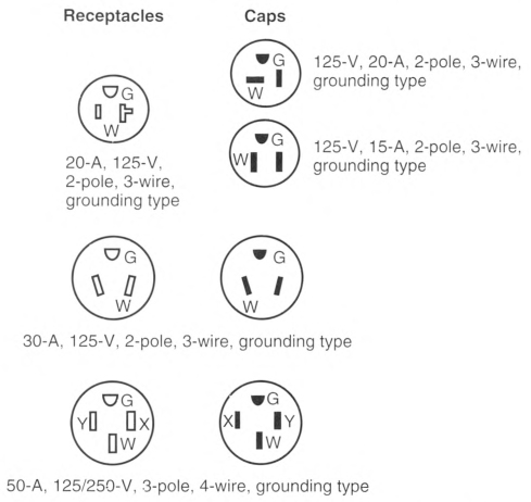
Exception No. 1: A recreational vehicle equipped with only a listed flexible drain system or a side-vent drain system shall be permitted to have the electrical point of entrance located on either side, provided the drain(s) for the plumbing system is (are) located on the same side.
Exception No. 2: A recreational vehicle shall be permitted to have the electrical point of entrance located more than 4.5 m (15 ft) from the rear. Where this occurs, the distance beyond the 4.5-m (15-ft) dimension shall be added to the cord's minimum length as specified in 551.46(B).
Exception No. 3: Recreational vehicles designed for transporting livestock shall be permitted to have the electrical point of entrance located on either side or the front.
FIGURE 551.46(C)(1) Configurations for Grounding-Type Receptacles and Attachment Plug Caps Used for Recreational Vehicle Supply Cords and Recreational Vehicle Lots.
551.47 Wiring Methods.
(A) Wiring Systems.
Cables and raceways installed in accordance with Articles 320, 322, 330 through 340, 342 through 362, 386, and 388 shall be permitted in accordance with their applicable article, except as otherwise specified in this article. An equipment grounding means shall be provided in accordance with 250.118.
(D) Boxes.
In walls and ceilings constructed of wood or other combustible material, boxes and fittings shall be flush with the finished surface or project therefrom.
(E) Mounting.
Wall and ceiling boxes shall be mounted in accordance with 314.23.
Exception No. 1: Snap-in-type boxes or boxes provided with special wall or ceiling brackets that securely fasten boxes in walls or ceilings shall be permitted.
(G) Protected.
Metal-clad, Type AC, or nonmetallic-sheathed cables and electrical nonmetallic tubing shall be permitted to pass through the centers of the wide side of 2 by 4 wood studs. However, they shall be protected where they pass through 2 by 2 wood studs or at other wood studs or frames where the cable or tubing would be less than 32 mm (11/4 in.) from the inside or outside surface. Steel plates on each side of the cable or tubing or a steel tube, with not less than 1.35 mm (0.053 in.) wall thickness, shall be installed to protect the cable or tubing. These plates or tubes shall be securely held in place. Where nonmetallic-sheathed cables pass through punched, cut, or drilled slots or holes in metal members, the cable shall be protected by bushings or grommets securely fastened in the opening prior to installation of the cable.
(H) Bends.
No bend shall have a radius of less than five times the cable diameter.
(I) Cable Supports.
Where connected with cable connectors or clamps, cables shall be secured and supported within 300 mm (12 in.) of outlet boxes, panelboards, and splice boxes on appliances. Supports and securing shall be provided at intervals not exceeding 1.4 m (41/2 ft) at other places.
(J) Nonmetallic Box Without Cable Clamps.
Nonmetallic-sheathed cables shall be secured and supported within 200 mm (8 in.) of a nonmetallic outlet box without cable clamps. Where wiring devices with integral enclosures are employed with a loop of extra cable to permit future replacement of the device, the cable loop shall be considered as an integral portion of the device.
(N) Moisture or Physical Damage.
Wiring shall be protected in accordance with the following:
- Where outdoor or under-chassis line-voltage (120 volts, nominal, or higher) wiring is exposed, it shall be protected by a conduit or raceway identified for use in wet locations. The conductors shall be listed for use in wet locations.
- Where wiring is exposed to physical damage, it shall be protected by a raceway.
(O) Component Interconnections.
Fittings and connectors that are intended to be concealed at the time of assembly shall be listed and identified for the interconnection of building components. Such fittings and connectors shall be equal to the wiring method employed in insulation, temperature rise, and fault-current withstanding and shall be capable of enduring the vibration and shock occurring in recreational vehicles.
(P) Method of Connecting Expandable Units.
The method of connecting expandable units to the main body of the vehicle shall comply with 551.47 (P)(1) or (P)(2).
(1) Cord-and-Plug-Connected.
Cord-and-plug connections shall comply with 551.47(P)(1)(a) through (P)(1)(d).
- That portion of a branch circuit that is installed in an expandable unit shall be permitted to be connected to the portion of the branch circuit in the main body of the vehicle by means of an attachment plug and cord listed for hard usage. The cord and its connections shall comply with Part I and Part II, as applicable, of Article 400 and shall be considered as a permitted use under 400.10. Where the attachment plug and cord are located within the vehicle's interior, use of plastic thermoset or elastomer parallel cord Type SPT-3, SP-3, or SPE shall be permitted.
- Where the receptacle provided for connection of the cord to the main circuit is located on the outside of the vehicle, it shall be protected with a ground-fault circuit interrupter for personnel and be listed for wet locations. A cord located on the outside of a vehicle shall be identified for outdoor use.
- Unless removable or stored within the vehicle interior, the cord assembly shall have permanent provisions for protection against corrosion and mechanical damage while the vehicle is in transit.
- The attachment plug and cord shall be installed so as not to permit exposed live attachment plug pins.
(2) Direct Wired.
That portion of a branch circuit that is installed in an expandable unit shall be permitted to be connected to the portion of the branch circuit in the main body of the vehicle by means of flexible cord installed in accordance with 551.47(P)(2)(a) through (P)(2)(e) or other approved wiring method.
- The flexible cord shall be listed for hard usage and for use in wet locations.
- The flexible cord shall be permitted to be exposed on the underside of the vehicle.
- The flexible cord shall be permitted to pass through the interior of a wall or floor assembly or both a maximum concealed length of 600 mm (24 in.) before terminating at an outlet or junction box.
- Where concealed, the flexible cord shall be installed in nonflexible conduit or tubing that is continuous from the outlet or junction box inside the recreational vehicle to a weatherproof outlet box, junction box, or strain relief fitting listed for use in wet locations that is located on the underside of the recreational vehicle. The outer jacket of the flexible cord shall be continuous into the outlet or junction box.
- Where the flexible cord passes through the floor to an exposed area inside of the recreational vehicle, it shall be protected by means of conduit and bushings or equivalent.
Where subject to physical damage, the flexible cord shall be protected with RMC, IMC, Schedule 80 PVC, reinforced thermosetting resin conduit (RTRC) listed for exposure to physical damage, or other approved means and shall extend at least 150 mm (6 in.) above the floor. A means shall be provided to secure the flexible cord where it enters the recreational vehicle.
(Q) Prewiring for Air-Conditioning Installation.
Prewiring installed for the purpose of facilitating future air-conditioning installation shall comply with the applicable portions of this article and the following:
- An overcurrent protective device with a rating compatible with the circuit conductors shall be installed in the panelboard and wiring connections completed.
- The load end of the circuit shall terminate in a junction box with a blank cover or other listed enclosure. Where a junction box with a blank cover is used, the free ends of the conductors shall be adequately capped or taped.
- A safety label with the signal word WARNING in minimum 6-mm (1/4-in.) high letters and body text in minimum 3-mm (1/8-in.) high letters on a contrasting background shall be affixed on or adjacent to the junction box and shall read as follows:WARNING
AIR-CONDITIONING CIRCUIT.
THIS CONNECTION IS FOR AIR CONDITIONERS RATED 110—125-VOLT AC, 60 HZ,
___ AMPERES MAXIMUM.
DO NOT EXCEED CIRCUIT RATING.EXCEEDING THE CIRCUIT RATING MAY
CAUSE A FIRE AND RESULT IN DEATH
OR SERIOUS INJURY.An ampere rating, not to exceed 80 percent of the circuit rating, shall be legibly marked in the blank space. - The circuit shall serve no other purpose.
(R) Prewiring for Generator Installation.
Prewiring installed for the purpose of facilitating future generator installation shall comply with the other applicable portions of this article and the following:
- Circuit conductors shall be appropriately sized in relation to the anticipated load as stated on the label required in 551.47(R)(4).
- Where junction boxes are utilized at either of the circuit originating or terminus points, free ends of the conductors shall be adequately capped or taped.
- Where devices such as receptacle outlet, transfer switch, and so forth, are installed, the installation shall be complete, including circuit conductor connections.
- A safety label with the signal word WARNING in minimum 6 mm (1/4 in.) high letters and body text in minimum 3 mm (1/8 in.) high letters on a contrasting background shall be affixed on the cover of each junction box or transfer switch containing incomplete circuitry and shall read, using one of the following warnings, as appropriate:
WARNING
GENERATOR
ONLY INSTALL A GENERATOR LISTED SPECIFICALLY
FOR RV USE HAVING OVERCURRENT
PROTECTION RATED 110—125-VOLT AC, 60 HZ,
__________ AMPERES MAXIMUM.
GENERATOR
ONLY INSTALL A GENERATOR LISTED SPECIFICALLY
FOR RV USE HAVING OVERCURRENT
PROTECTION RATED 110—125-VOLT AC, 60 HZ,
__________ AMPERES MAXIMUM.
or
WARNING
GENERATOR
ONLY INSTALL A GENERATOR LISTED SPECIFICALLY
FOR RV USE HAVING OVERCURRENT
PROTECTION RATED 120-240-VOLT AC, 60 HZ,
__________ AMPERES MAXIMUM.
GENERATOR
ONLY INSTALL A GENERATOR LISTED SPECIFICALLY
FOR RV USE HAVING OVERCURRENT
PROTECTION RATED 120-240-VOLT AC, 60 HZ,
__________ AMPERES MAXIMUM.
The correct ampere rating shall be legibly marked in the blank space.
(S) Prewiring for Other Circuits.
Prewiring installed for the purpose of installing other appliances or devices shall comply with the applicable portions of this article and the following:
- An overcurrent protection device with a rating compatible with the circuit conductors shall be installed in the panelboard with wiring connections completed.
- The load end of the circuit shall terminate in a junction box with a blank cover or a device listed for the purpose. Where a junction box with blank cover is used, the free ends of the conductors shall be adequately capped or taped.
- A safety label with the signal word WARNING in minimum 6-mm (1/4-in.) high letters and body text in minimum 3-mm (1/8-in.) high letters on a contrasting background shall be affixed on or adjacent to the junction box or device listed for the purpose and shall read as follows:
WARNING
THIS CONNECTION IS FOR _________ RATED __________ VOLT
AC, 60 HZ, ______ AMPERES MAXIMUM. DO NOT
EXCEED CIRCUIT RATING.
EXCEEDING THE CIRCUIT RATING MAY
CAUSE A FIRE AND RESULT IN DEATH OR
SERIOUS INJURY.
THIS CONNECTION IS FOR _________ RATED __________ VOLT
AC, 60 HZ, ______ AMPERES MAXIMUM. DO NOT
EXCEED CIRCUIT RATING.
EXCEEDING THE CIRCUIT RATING MAY
CAUSE A FIRE AND RESULT IN DEATH OR
SERIOUS INJURY.
An ampere rating not to exceed 80 percent of the circuit rating shall be legibly marked in the blank space.
551.51 Switches.
(A) Rating.
(1) Lighting Circuits.
For lighting circuits, switches shall be rated not less than 10 amperes, 120—125 volts and in no case less than the connected load.
(B) Location.
Switches shall not be installed within wet locations in tub or shower spaces unless installed as part of a listed tub or shower assembly.
551.52 Receptacles.
All receptacle outlets shall be of the grounding type and installed in accordance with 406.4 and 210.21.
551.53 Luminaires and Other Equipment.
(B) Shower Luminaires.
If a luminaire is provided over a bathtub or in a shower stall, it shall be of the enclosed and gasketed type and listed for the type of installation, and it shall be ground-fault circuit-interrupter protected.
551.54 Grounding.
(A) Power-Supply Grounding.
The equipment grounding conductor in the supply cord or feeder shall be connected to the equipment grounding bus or other approved equipment grounding means in the panelboard.
(B) Panelboard.
The panelboard shall have an equipment grounding bus with terminals for all equipment grounding conductors or other approved equipment grounding means.
(C) Insulated Neutral Conductor.
The neutral conductor shall be insulated from the equipment grounding conductors and from equipment enclosures and other grounded parts. The neutral conductor terminals in the panelboard and in ranges, clothes dryers, counter-mounted cooking units, and wall-mounted ovens shall be insulated from the equipment enclosure. Bonding screws, straps, or buses in the panelboard or in appliances shall be removed and discarded. Connection of electric ranges and electric clothes dryers utilizing a grounded conductor, if cord-connected, shall be made with 4-conductor cord and 3-pole, 4-wire grounding-type plug caps and receptacles.
551.55 Interior Equipment Grounding.
(A) Exposed Metal Parts.
In the electrical system, all exposed metal parts, enclosures, frames, luminaire canopies, and so forth, shall be effectively bonded to the grounding terminals or enclosure of the panelboard.
(B) Equipment Grounding and Bonding Conductors.
Bare wires, insulated wire with an outer finish that is green or green with one or more yellow stripes, shall be used for equipment grounding or bonding conductors only.
(C) Grounding of Electrical Equipment.
Grounding of electrical equipment shall be accomplished by one or more of the following methods:
- Connection of metal raceway, the sheath of Type MC and Type MI cable where the sheath is identified for grounding, or the armor of Type AC cable to metal enclosures.
- A connection between the one or more equipment grounding conductors and a metal enclosure by means of a grounding screw, which shall be used for no other purpose, or a listed grounding device.
- The equipment grounding conductor in nonmetallic-sheathed cable shall be permitted to be secured under a screw threaded into the luminaire canopy other than a mounting screw or cover screw, or attached to a listed grounding means (plate) in a nonmetallic outlet box for luminaire mounting. [Grounding means shall also be permitted for luminaire attachment screws.]
(E) Grounding Continuity.
Where more than one equipment grounding or bonding conductor of a branch circuit enters a box, all such conductors shall be connected together using a method specified in 250.8, and the arrangement shall be such that the disconnection or removal of a receptacle, luminaire, or other device fed from the box will not interfere with or interrupt the grounding continuity.
(F) Cord-Connected Appliances.
Cord-connected appliances, such as washing machines, clothes dryers, refrigerators, and the electrical system of gas ranges, and so forth, shall be grounded by means of an approved cord with equipment grounding conductor and grounding-type attachment plug.
551.56 Bonding of Non-Current-Carrying Metal Parts.
(A) Required Bonding.
All exposed non—current-carrying metal parts that are likely to become energized shall be effectively bonded to the grounding terminal or enclosure of the panelboard.
(B) Bonding Chassis.
A bonding conductor shall be connected between any panelboard and an accessible terminal on the chassis. Bonding terminations shall be suitable for the environment in which the conductors and terminations are installed.
Exception: Any recreational vehicle that employs a unitized metal chassis-frame construction to which the panelboard is securely fastened with a bolt(s) and nut(s) or by welding or riveting shall be considered to be bonded.
(C) Bonding Conductor Requirements.
Grounding terminals shall be of the solderless type and listed as pressure terminal connectors recognized for the wire size used. The bonding conductor shall be solid or stranded, insulated or bare, and shall be 8 AWG copper minimum, or equal.
(D) Metallic Roof and Exterior Bonding.
The metal roof and exterior covering shall be considered bonded where both of the following conditions apply:
- The metal panels overlap one another and are securely attached to the wood or metal frame parts by metal fasteners.
- The lower panel of the metal exterior covering is secured by metal fasteners at each cross member of the chassis, or the lower panel is connected to the chassis by a metal strap.
(E) Gas, Water, and Waste Pipe Bonding.
The gas, water, and waste pipes shall be considered grounded if they are bonded to the chassis.
(F) Furnace and Metal Air Duct Bonding.
Furnace and metal circulating air ducts shall be bonded.
551.57 Appliance Accessibility and Fastening.
Every appliance shall be accessible for inspection, service, repair, and replacement without removal of permanent construction. Means shall be provided to securely fasten appliances in place when the recreational vehicle is in transit.
551.60 Factory Tests (Electrical).
Each recreational vehicle designed with a 120-volt or a 120/240-volt electrical system shall withstand the applied voltage without electrical breakdown of a 1-minute, 900-volt ac or 1280-volt dc dielectric strength test, or a 1-second, 1080-volt ac or 1530-volt dc dielectric strength test, with all switches closed, between ungrounded and grounded conductors and the recreational vehicle ground. During the test, all switches and other controls shall be in the "on" position. Fixtures, including luminaires and permanently installed appliances, shall not be required to withstand this test. The test shall be performed after branch circuits are complete prior to energizing the system and again after all outer coverings and cabinetry have been secured. The dielectric test shall be performed in accordance with the test equipment manufacturer's written instructions.
Each recreational vehicle shall be subjected to all of the following:
- A continuity test to ensure that all metal parts are properly bonded
- Operational tests to demonstrate that all equipment is properly connected and in working order
- Polarity checks to determine that connections have been properly made
- GFCI test to demonstrate that the ground fault protection device(s) installed on the recreational vehicle are operating properly
551.71 Type Receptacles Provided.
(A) 20-Ampere.
Every recreational vehicle site with electrical supply shall be equipped with recreational vehicle site supply equipment with at least one 20-ampere, 125-volt weather-resistant receptacle. This receptacle, when used in recreational vehicle site electrical equipment, shall not be required to be tamper-resistant in accordance with 406.12.
(B) 30-Ampere.
A minimum of 70 percent of all recreational vehicle sites with electrical supply shall each be equipped with a 30-ampere, 125-volt weather-resistant receptacle conforming to Figure 551.46(C)(1). This supply shall be permitted to include additional receptacle configurations conforming to 551.81. The remainder of all recreational vehicle sites with electrical supply shall be equipped with one or more of the receptacle configurations conforming to 551.81.
(C) 50-Ampere.
A minimum of 20 percent of existing and 40 percent of all new recreational vehicle sites with electrical supply, shall each be equipped with a 50-ampere, 125/250-volt weather-resistant receptacle conforming to the configuration as identified in Figure 551.46(C)(1). Every recreational vehicle site equipped with a 50-ampere receptacle shall also be equipped with a 30-ampere, 125-volt receptacle conforming to Figure 551.46(C)(1). These electrical supplies shall be permitted to include additional receptacles that have configurations in accordance with 551.81. The weather-resistant requirement for 50-ampere, 125/250-volt receptacles shall become effective January 1, 2026.
Informational Note: The percentage of 50 ampere sites required by 551.71 could be inadequate for seasonal recreational vehicle sites serving a higher percentage of recreational vehicles with 50-ampere electrical systems. In that type of recreational vehicle park, the percentage of 50-ampere sites could approach 100 percent.
(D) Tent Sites.
Dedicated tent sites with a 15- or 20-ampere electrical supply shall be permitted to be excluded when determining the percentage of recreational vehicle sites with 30- or 50-ampere receptacles.
(E) Additional Receptacles.
Additional receptacles shall be permitted for the connection of electrical equipment outside the recreational vehicle within the recreational vehicle park.
(F) GFCI Protection.
(2) Receptacles Installed in Recreational Vehicle Site Equipment.
Ground-fault circuit-interrupter protection shall only be required for 125-volt, single-phase, 15- and 20-ampere receptacles.
Informational Note No. 1: Appliances used within the recreational vehicle can create leakage current levels at the supply receptacle(s) that could exceed the limits of a Class A GFCI device.
Informational Note No. 2: The definition of Feeder Assembly clarifies that the power supply cord to a recreational vehicle is considered a feeder.
551.72 Distribution System.
(A) Systems.
Distribution systems shall provide the voltage and have a capacity for the receptacles provided in the recreational vehicle (RV) site supply equipment as calculated according to 551.73 and shall have an ampacity not less than 30 amperes. Systems permitted include single-phase 120 volts, single-phase 120/240 volts, or single-phase 120/208 volts - two ungrounded and one neutral conductor taken from a 208Y/120-volt system.
(B) Three-Phase Systems.
Feeders from 208Y/120-volt, 3-phase systems shall be permitted to include two ungrounded conductors and shall include one grounded conductor and one equipment grounding conductor. So far as practicable, the loads shall be equally distributed on the 3-phase system.
(C) Receptacles.
Receptacles rated at 50 amperes shall be supplied from a circuit of the voltage class and rating of the receptacle. Other recreational vehicle sites with 125-volt, 20- and 30-ampere receptacles shall be permitted to be derived from any grounded distribution system that supplies 120-volt, single-phase power.
(D) Neutral Conductors.
Neutral conductors shall be permitted to be reduced in size below the minimum required size of the ungrounded conductors for 240-volt, line-to-line, permanently connected loads only. The neutral conductors shall not be reduced in size below the size of the ungrounded conductors for the site distribution.
Informational Note: Due to the long circuit lengths typical in most recreational vehicle parks, feeder conductor sizes found in the ampacity tables of Article 310 could be inadequate to maintain the voltage regulation suggested in 215.2(A), Informational Note No. 2. Total circuit voltage drop is a sum of the voltage drops of each serial circuit segment, where the load for each segment is calculated using the load that segment sees and the demand factors shown in Table 551.73(A).
(F) Connection to Recreational Vehicle Site Equipment.
Each recreational vehicle shall be powered by only one 30-ampere or one 50-ampere external power supply cord.
Informational Note: The requirement in 551.72(F) does not preclude the use of the 15- or 20-ampere receptacle convenience outlet on the recreational vehicle supply equipment.
551.73 Calculated Load.
(A) Basis of Calculations.
Electrical services and feeders shall be calculated on the basis of not less than all of the following:
- 12,000 volt-amperes per site equipped with 50-ampere, 208Y/120-volt or 120/240-volt supply facilities
- 3600 volt-amperes per site equipped with both 20-ampere and 30-ampere supply facilities
- 2400 volt-amperes per site equipped with only 20-ampere supply facilities
- 600 volt-amperes per site equipped with only 20-ampere supply facilities that are dedicated to tent sites
The demand factors set forth in Table 551.73(A) shall be the minimum allowable demand factors that shall be permitted in calculating load for service and feeders. Where the electrical supply for a recreational vehicle site has more than one receptacle.
Where the electrical supply is in a location that serves two recreational vehicles, the equipment for both sites shall comply with 551.77, and the calculated load shall only be calculated for the two receptacles with the highest rating.
(B) Demand Factors.
The demand factor for a given number of sites shall apply to all sites indicated. For example, 20 sites calculated at 45 percent of 3600 volt-amperes results in a permissible demand of 1620 volt-amperes per site or a total of 32,400 volt-amperes for 20 sites.
Informational Note: These demand factors may be inadequate in areas of extreme hot or cold temperature with loaded circuits for heating or air conditioning.
Loads for other amenities such as, but not limited to, service buildings, recreational buildings, and swimming pools shall be calculated separately and then be added to the value calculated for the recreational vehicle sites where they are all supplied by a common service.
Table 551.73(A) Demand Factors for Site Feeders and Service-Entrance Conductors for Park Sites.
| Number of Recreational Vehicle Sites | Demand Factor (%) |
|---|---|
| 1 | 100 |
| 2 | 90 |
| 3 | 80 |
| 4 | 75 |
| 5 | 65 |
| 6 | 60 |
| 7—9 | 55 |
| 10—12 | 50 |
| 13—15 | 48 |
| 16—18 | 47 |
| 19—21 | 45 |
| 22—24 | 43 |
| 25—35 | 42 |
| 36 plus | 41 |
551.76 Grounding - Recreational Vehicle Site Supply Equipment.
(A) Grounding Electrode.
Recreational vehicle site supply equipment, other than those used as service equipment, shall not be required to have a grounding electrode. An auxiliary grounding electrode(s) in accordance with 250.54 shall be permitted to be installed.
(B) Exposed Non—Current-Carrying Metal Parts.
Exposed non—current-carrying metal parts of fixed equipment, metal boxes, cabinets, and fittings that are not electrically connected to grounded equipment shall be grounded by an equipment grounding conductor run with the circuit conductors from the service equipment or from the transformer of a secondary distribution system. Equipment grounding conductors shall be sized in accordance with 250.122 and shall be permitted to be spliced by listed means.
The arrangement of equipment grounding connections shall be such that the disconnection or removal of a receptacle or other device will not interfere with, or interrupt, the grounding continuity.
(D) Grounded Conductor Not to Be Used as an Equipment Ground.
The grounded conductor shall not be used as an equipment grounding conductor for recreational vehicles or equipment within the recreational vehicle park.
(E) No Connection on the Load Side.
No connection to a grounding electrode shall be made to the grounded conductor on the load side of the service disconnecting means except as covered in 250.30(A) for separately derived systems, and 250.32(B), Exception No. 1 for separate buildings.
551.77 Recreational Vehicle Site Supply Equipment.
Recreational vehicle site supply equipment shall be listed for use as recreational vehicle site supply equipment and shall comply with 551.77(A) through (F).
(A) Location.
Where provided on back-in sites, the recreational vehicle site electrical supply equipment shall be located on the left (road) side of the parked vehicle, on a line that is 1.5 m to 2.1 m (5 ft to 7 ft) from the left edge (driver's side of the parked RV) of the recreational vehicle stand and shall be located at any point on this line from the rear of the recreational vehicle stand to 4.5 m (15 ft) forward of the rear of the recreational vehicle stand.
For pull-through sites, the electrical supply equipment shall be permitted to be located at any point along the line that is 1.5 m to 2.1 m (5 ft to 7 ft) from the left edge (driver's side of the parked RV) from 4.9 m (16 ft) forward of the rear of the recreational vehicle stand to the center point between the two roads that gives access to and egress from the pull-through sites.
The left edge (driver's side of the parked RV) of the recreational vehicle stand shall be marked.
(B) Disconnecting Means.
A disconnecting switch or circuit breaker shall be provided in the site supply equipment for disconnecting the power supply to the recreational vehicle.
(C) Access.
All site supply equipment shall be accessible by an unobstructed entrance or passageway not less than 600 mm (2 ft) wide and 2.0 m (6 ft 6 in.) high.
(D) Mounting Height.
Site supply equipment shall be located not less than 600 mm (2 ft) above the electrical datum plane for that RV site and no more than 2.0 m (6 ft 6 in.) above the electrical datum plane unless platform provisions are made to reach the circuit protection devices that are no more than 2.0 m (6 ft 6 in.) above that platform.
(F) Marking.
Where the site supply equipment contains a 125/250-volt receptacle, the equipment shall be marked as follows: "Turn disconnecting switch or circuit breaker off before inserting or removing plug. Plug must be fully inserted or removed." The marking shall be located on the equipment adjacent to the receptacle outlet.
551.78 Protection of Outdoor Equipment.
(A) Wet Locations.
All switches, circuit breakers, receptacles, control equipment, and metering devices located in wet locations shall be weatherproof.
(B) Meters.
If secondary meters are installed, meter sockets without meters installed shall be blanked off with an approved blanking plate.
551.79 Clearance for Overhead Conductors.
551.80 Underground Service, Feeder, Branch-Circuit, and Recreational Vehicle Site Feeder-Circuit Conductors.
(A) General.
All direct-burial conductors, including the equipment grounding conductor if of aluminum, shall be insulated and identified for the use. All conductors shall be continuous from equipment to equipment. All splices and taps shall be made in approved junction boxes or by use of listed material.
(B) Protection Against Physical Damage.
Direct-buried conductors and cables entering or leaving a trench shall be protected by rigid metal conduit, intermediate metal conduit, electrical metallic tubing with supplementary corrosion protection, rigid polyvinyl chloride conduit (PVC), nonmetallic underground conduit with conductors (NUCC), high density polyethylene conduit (HDPE), reinforced thermosetting resin conduit (RTRC), liquidtight flexible nonmetallic conduit, liquidtight flexible metal conduit, or other approved raceways or enclosures. Where subject to physical damage, the conductors or cables shall be protected by rigid metal conduit, intermediate metal conduit, Schedule 80 PVC conduit, or RTRC listed for exposure to physical damage. All such protection shall extend at least 450 mm (18 in.) into the trench from finished grade.
Informational Note: See 300.5 and Article 340 for conductors or Type UF cable used underground or in direct burial in earth.
551.81 Receptacles.
A receptacle to supply electric power to a recreational vehicle shall be one of the configurations shown in Figure 551.46(C)(1) in the following ratings:
- 50-ampere - 125/250-volt, 50-ampere, 3-pole, 4-wire grounding type for 120/240-volt systems
- 30-ampere - 125-volt, 30-ampere, 2-pole, 3-wire grounding type for 120-volt systems
- 20-ampere - 125-volt, 20-ampere, 2-pole, 3-wire grounding type for 120-volt systems
Informational Note: See ANSI/NEMA WD 6-2016, Wiring Devices - Dimensional Specifications, Figures 14-50, TT, and 5-20, for complete details of these configurations.
Article 552
Park Trailers
552.1 Scope.
The provisions of this article cover the electrical conductors and equipment installed within or on park trailers not covered fully under Articles 550 and 551.
552.4 General Requirements.
A park trailer is intended for seasonal use. It is not intended as a permanent dwelling unit or for commercial uses such as banks, clinics, offices, or similar. Units designed for such purposes are classified as relocatable structures and are covered in Part II of Article 545.
552.5 Labels.
Labels required by Article 552 shall be made of etched, metal-stamped, or embossed brass or stainless steel; plastic laminates not less than 0.13 mm (0.005 in.) thick; or anodized or alclad aluminum not less than 0.5 mm (0.020 in.) thick or the equivalent.
Informational Note: See ANSI Z535.4-2011, Product Safety Signs and Labels, for guidance on other label criteria used in the park trailer industry.
552.10 Low-Voltage Systems.
(A) Low-Voltage Circuits.
Low-voltage circuits furnished and installed by the park trailer manufacturer, other than those related to braking, shall be subject to this Code. Circuits supplying lights subject to federal or state regulations shall comply with applicable government regulations and this Code.
(B) Low-Voltage Wiring.
(2) Conductor Types.
Conductors shall conform to the requirements for Type GXL, HOT, SGT, SGR, or Type SXL or shall have insulation in accordance with Table 310.4(1) or the equivalent. Conductor sizes 6 AWG through 18 AWG or SAE shall be listed. Single-wire, low-voltage conductors shall be of the stranded ty pe.
(3) Marking.
All insulated low-voltage conductors shall be surface marked at intervals not greater than 1.2 m (4 ft) as follows:
- Listed conductors shall be marked as required by the listing agency.
- SAE conductors shall be marked with the name or logo of the manufacturer, specification designation, and wire gauge.
- Other conductors shall be marked with the name or logo of the manufacturer, temperature rating, wire gauge, conductor material, and insulation thickness.
(C) Low-Voltage Wiring Methods.
(1) Physical Protection.
Conductors shall be protected against physical damage and shall be secured. Where insulated conductors are clamped to the structure, the conductor insulation shall be supplemented by an additional wrap or layer of equivalent material, except that jacketed cables shall not be required to be so protected. Wiring shall be routed away from sharp edges, moving parts, or heat sources.
(2) Splices.
Conductors shall be spliced or joined with splicing devices that provide a secure connection or by brazing, welding, or soldering with a fusible metal or alloy. Soldered splices shall first be spliced or joined to be mechanically and electrically secure without solder, and then soldered. All splices, joints, and free ends of conductors shall be covered with an insulation equivalent to that on the conductors.
(3) Separation.
Battery and other low-voltage circuits shall be physically separated by at least a 13-mm (1/2-in.) gap or other approved means from circuits of a different power source. Acceptable methods shall be by clamping, routing, or equivalent means that ensure permanent total separation. Where circuits of different power sources cross, the external jacket of the nonmetallic-sheathed cables shall be deemed adequate separation.
(4) Ground Connections.
Ground connections to the chassis or frame shall be made in an accessible location and shall be mechanically secure. Ground connections shall be by means of copper conductors and copper or copper-alloy terminals of the solderless type identified for the size of wire used. The surface on which ground terminals make contact shall be cleaned and be free from oxide or paint or shall be electrically connected through the use of a cadmium, tin, or zinc-plated internal/external-toothed lockwasher or locking terminals. Ground terminal attaching screws, rivets or bolts, nuts, and lockwashers shall be cadmium, tin, or zinc-plated except rivets shall be permitted to be unanodized aluminum where attaching to aluminum structures.
(D) Battery Installations.
Storage batteries subject to this Code shall be securely attached to the unit and installed in an area vaportight to the interior and ventilated directly to the exterior of the unit. Where batteries are installed in a compartment, the compartment shall be ventilated with openings having a minimum area of 1100 mm2 (1.7 in.2) at both the top and at the bottom. Where compartment doors are equipped for ventilation, the openings shall be within 50 mm (2 in.) of the top and bottom. Batteries shall not be installed in a compartment containing spark- or flame-producing equipment.
(E) Overcurrent Protection.
(1) Rating.
Low-voltage circuit wiring shall be protected by overcurrent protective devices rated not in excess of the ampacity of copper conductors, in accordance with Table 552.10(E)(1).
(2) Type.
Circuit breakers or fuses shall be of an approved type, including automotive types. Fuseholders shall be clearly-marked with maximum fuse size and shall be protected against shorting and physical damage by a cover or equivalent means.
(3) Appliances.
Appliances such as pumps, compressors, heater blowers, and similar motor-driven appliances shall be installed in accordance with the manufacturer's instructions.
(4) Location.
The overcurrent protective device shall be installed in an accessible location on the unit within 450 mm (18 in.) of the point where the power supply connects to the unit circuits. If located outside the park trailer, the device shall be protected against weather and physical damage.
Exception: External low-voltage supply shall be permitted to have the overcurrent protective device within 450 mm (18 in.) after entering the unit or after leaving a metal raceway.
(F) Switches.
Switches shall have a dc rating not less than the connected load.
(G) Luminaires.
All low-voltage interior luminaires rated more than 4 watts, employing lamps rated more than 1.2 watts, shall be listed.
552.20 Combination Electrical Systems.
(A) General.
Unit wiring suitable for connection to a battery or other low-voltage supply source shall be permitted to be connected to a 120-volt source, provided that the entire wiring system and equipment are rated and installed in full conformity with Parts I, III, IV, and V requirements of this article covering 120-volt electrical systems. Circuits fed from ac transformers shall not supply dc appliances.
(B) Voltage Converters (120-Volt Alternating Current to Low-Voltage Direct Current).
The 120-volt ac side of the voltage converter shall be wired in full conformity with the requirements of Parts I and IV of this article for 120-volt electrical systems.
Exception: Converters supplied as an integral part of a listed appliance shall not be subject to 552.20(B).
All converters and transformers shall be listed for use in recreation units and designed or equipped to provide overtemperature protection. To determine the converter rating, the following percentages shall be applied to the total connected load, including average battery-charging rate, of all 12-volt equipment:
The first 20 amperes of load at 100 percent plus
The second 20 amperes of load at 50 percent plus
All load above 40 amperes at 25 percent
Exception: A low-voltage appliance that is controlled by a momentary switch (normally open) that has no means for holding in the closed position shall not be considered as a connected load when determining the required converter rating. Momentarily energized appliances shall be limited to those used to prepare the unit for occupancy or travel.
(D) Dual-Voltage Fixtures Including Luminaires or Appliances.
Fixtures, including luminaires, or appliances having both 120-volt and low-voltage connections shall be listed for dual voltage.
(E) Autotransformers.
Autotransformers shall not be used.
(F) Receptacles and Plug Caps.
Where a park trailer is equipped with a 120-volt or 120/240-volt ac system, a low-voltage system, or both, receptacles and plug caps of the low-voltage system shall differ in configuration from those of the 120-volt or 120/240-volt system. Where a unit equipped with a battery or dc system has an external connection for low-voltage power, the connector shall have a configuration that will not accept 120-volt power.
552.40 120-Volt or 120/240-Volt, Nominal, Systems.
(A) General Requirements.
The electrical equipment and material of park trailers indicated for connection to a wiring system rated 120 volts, nominal, 2-wire with an equipment grounding conductor, or a wiring system rated 120/240 volts, nominal, 3-wire with an equipment grounding conductor, shall be listed and installed in accordance with Parts I, III, IV, and V of this article.
(B) Materials and Equipment.
Electrical materials, devices, appliances, fittings, and other equipment installed, intended for use in, or attached to the park trailer shall be listed. All products shall be used only in the manner in which they have been tested and found suitable for the intended use.
552.41 Receptacle Outlets Required.
(A) Spacing.
Receptacle outlets shall be installed at wall spaces 600 mm (2 ft) wide or more so that no point along the floor line is more than 1.8 m (6 ft), measured horizontally, from an outlet in that space.
Exception No. 1: Bath and hallway areas shall not be required to comply with 552.41(A).
(B) Location.
Receptacle outlets shall be installed as follows:
- Adjacent to countertops in the kitchen [at least one on each side of the sink if countertops are on each side and are 300 mm (12 in.) or over in width and depth]
- Adjacent to the refrigerator and gas range space, except where a gas-fired refrigerator or cooking appliance, requiring no external electrical connection, is factory-installed
- Adjacent to countertop spaces of 300 mm (12 in.) or more in width and depth that cannot be reached from a receptacle required in 552.41(B)(1) by a cord of 1.8 m (6 ft) without crossing a traffic area, cooking appliance, or sink
(C) Ground-Fault Circuit-Interrupter Protection.
Each 125-volt, single-phase, 15- or 20-ampere receptacle shall have ground-fault circuit-interrupter protection for personnel in the following locations:
- Where the receptacles are installed to serve kitchen countertop surfaces
- Within 1.8 m (6 ft) of any lavatory or sinkException: Receptacles installed for appliances in dedicated spaces, such as for dishwashers, disposals, refrigerators, freezers, and laundry equipment.
- In the area occupied by a toilet, shower, tub, or any combination thereof
- On the exterior of the unit
Exception: Receptacles that are located inside of an access panel that is installed on the exterior of the unit to supply power for an installed appliance shall not be required to have ground-fault circuit-interrupter protection.
The receptacle outlet shall be permitted in a listed luminaire. A receptacle outlet shall not be installed in a tub or combination tub-shower compartment.
(D) Pipe Heating Cable Outlet.
Where a pipe heating cable outlet is installed, the outlet shall be as follows:
- Located within 600 mm (2 ft) of the cold water inlet
- Connected to an interior branch circuit, other than a small-appliance branch circuit
- On a circuit where all of the outlets are on the load side of the ground-fault circuit-interrupter protection for personnel
- Mounted on the underside of the park trailer and shall not be considered to be the outdoor receptacle outlet required in 552.41 (E)
(E) Outdoor Receptacle Outlets.
At least one receptacle outlet shall be installed outdoors. A receptacle outlet located in a compartment accessible from the outside of the park trailer shall be considered an outdoor receptacle. Outdoor receptacle outlets shall be protected as required in 552.41 (C)(4).
(F) Receptacle Outlets Not Permitted.
(1) Shower or Bathtub Space.
Receptacle outlets shall not be installed in or within reach [750 mm (30 in.)] of a shower or bathtub space.
(2) Face-Up Position.
A receptacle shall not be installed in a face-up position in any countertop or other similar horizontal surface.
552.42 Branch-Circuit Protection.
(A) Rating.
The branch-circuit overcurrent devices shall be rated as follows:
- Not more than the circuit conductors
- Not more than 150 percent of the rating of a single appliance rated 13.3 amperes or more and supplied by an individual branch circuit
- Not more than the overcurrent protection size marked on an air conditioner or other motor-operated appliances.
(B) Protection for Smaller Conductors.
A 20-ampere fuse or circuit breaker shall be permitted for protection for fixtures, including luminaires, leads, cords, or small appliances, and 14 AWG tap conductors, not over 1.8 m (6 ft) long for recessed luminaires.
(C) Fifteen-Ampere Receptacle Considered Protected by 20 Amperes.
If more than one receptacle or load is on a branch circuit, 15-ampere receptacles shall be permitted to be protected by a 20-ampere fuse or circuit breaker.
552.43 Power Supply.
(A) Feeder.
The power supply to the park trailer shall be a feeder assembly consisting of not more than one listed 30-ampere or 50-ampere park trailer power-supply cord, with an integrally molded or securely attached cap, or a permanently installed feeder.
(B) Power-Supply Cord.
If the park trailer has a power-supply cord, it shall be permanently attached to the panelboard, or to a junction box permanently connected to the panelboard, with the free end terminating in a molded-on attachment plug cap.
Cords with adapters and pigtail ends, extension cords, and similar items shall not be attached to, or shipped with, a park trailer.
A suitable clamp or the equivalent shall be provided at the panelboard knockout to afford strain relief for the cord to prevent strain from being transmitted to the terminals when the power-supply cord is handled in its intended manner.
The cord shall be a listed type with 3-wire, 120-volt or 4-wire, 120/240-volt conductors, one of which shall be identified by a continuous green color or a continuous green color with one or more yellow stripes for use as the equipment grounding conductor.
(C) Mast Weatherhead or Raceway.
Where the calculated load exceeds 50 amperes or where a permanent feeder is used, the supply shall be by means of one of the following:
- One mast weatherhead installation, installed in accordance with Article 230, containing four continuous, insulated, color-coded feeder conductors, one of which shall be an equipment grounding conductor
- A rigid metal conduit, intermediate metal conduit, rigid polyvinyl chloride conduit, or other raceways identified for the location from the disconnecting means in the park trailer to the underside of the park trailer
552.44 Cord.
(A) Permanently Connected.
Each feeder assembly shall be factory supplied or factory installed and connected directly to the terminals of the panelboard or conductors within a junction box and provided with means to prevent strain from being transmitted to the terminals. The ampacity of the conductors between each junction box and the terminals of each panelboard shall be at least equal to the ampacity of the feeder cord. The supply end of the assembly shall be equipped with an attachment plug of the type described in 552.44(C). Where the cord passes through the walls or floors, it shall be protected by means of conduit and bushings or equivalent. The cord assembly shall have permanent provisions for protection against corrosion and mechanical damage while the unit is in transit.
(B) Cord Length.
The cord-exposed usable length shall be measured from the point of entrance to the park trailer or the face of the flanged surface inlet (motor-base attachment plug) to the face of the attachment plug at the supply end.
The cord-exposed usable length, measured to the point of entry on the unit exterior, shall be a minimum of 7.0 m (23 ft) where the point of entrance is at the side of the unit, or shall be a minimum 8.5 m (28 ft) where the point of entrance is at the rear of the unit. The maximum length shall not exceed 11 m (361/2 ft).
Where the cord entrance into the unit is more than 900 mm (3 ft) above the ground, the minimum cord lengths above shall be increased by the vertical distance of the cord entrance heights above 900 mm (3 ft).
(C) Attachment Plugs.
(1) Units With Two to Five 15- or 20-Ampere Branch Circuits.
Park trailers wired in accordance with 552.46(A) shall have an attachment plug that shall be 2-pole, 3-wire grounding type, rated 30 amperes, 125 volts, conforming to the configuration shown in Figure 552.44(C)(1) intended for use with units rated at 30 amperes, 125 volts.
Informational Note: See ANSI/NEMA WD 6-2016, Wiring Devices - Dimensional Specifications, Figure TT, for complete details of this configuration.
(2) Units With 50-Ampere Feeder Assembly.
Park trailers having a feeder assembly rated 50 amperes as permitted by 552.43(B) shall have a 3-pole, 4-wire grounding-type attachment plug rated 50 amperes, 125/250 volts, conforming to the configuration shown in Figure 552.44(C)(1).
Informational Note: See ANSI/NEMA WD 6-2016, Wiring Devices - Dimensional Specifications, Figure 14-50, for complete details of this configuration.
(D) Labeling at Electrical Entrance.
Each park trailer shall have a safety label with the signal word WARNING in minimum 6 mm (1/4 in.) high letters and body text in minimum 3 mm (1/8 in.) high letters on a contrasting background. The safety label shall be affixed to the exterior skin, at or near the point of entrance of the feeder assembly and shall read, as appropriate:
WARNING:
THIS CONNECTION IS FOR 110—125-VOLT AC,
60 HZ, 30-AMPERE SUPPLY
THIS CONNECTION IS FOR 110—125-VOLT AC,
60 HZ, 30-AMPERE SUPPLY
or
WARNING:
THIS CONNECTION IS FOR 208Y/120-VOLT OR 120/240-VOLT AC,
3-POLE, 4-WIRE, 60 HZ, _______ AMPERE SUPPLY.
THIS CONNECTION IS FOR 208Y/120-VOLT OR 120/240-VOLT AC,
3-POLE, 4-WIRE, 60 HZ, _______ AMPERE SUPPLY.
followed by
DO NOT EXCEED THE CIRCUIT RATING. EXCEEDING
THE CIRCUIT RATING CAN CAUSE A FIRE AND RESULT
IN DEATH OR SERIOUS INJURY.
THE CIRCUIT RATING CAN CAUSE A FIRE AND RESULT
IN DEATH OR SERIOUS INJURY.
(E) Location.
The point of entrance of a feeder assembly shall be located on either side or the rear, within 450 mm (18 in.), of an outside wall. 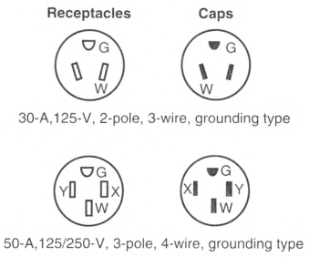
FIGURE 552.44(C)(1) Attachment Cap and Receptacle Configurations.
552.45 Panelboard.
(A) Listed and Appropriately Rated.
A listed and appropriately rated panelboard shall be used. The grounded conductor termination bar shall be insulated from the enclosure as provided in 552.55(C). An equipment grounding terminal bar shall be attached inside the metal enclosure of the panelboard.
(B) Location.
The panelboard shall be installed in a readily accessible location. Working clearance for the panelboard shall be not less than 600 mm (24 in.) wide and 750 mm (30 in.) deep.
Exception: Where the panelboard cover is exposed to the inside aisle space, one of the working clearance dimensions shall be permitted to be reduced to a minimum of 550 mm (22 in.). A panelboard shall be considered exposed where the panelboard cover is within 50 mm (2 in.) of the aisle's finished surface or not more than 25 mm (1 in.) from the backside of doors that enclose the space.
(C) Dead-Front Type.
The panelboard shall be of the dead-front type. A main disconnecting means shall be provided where fuses are used or where more than two circuit breakers are employed. A main overcurrent protective device not exceeding the feeder assembly rating shall be provided where more than two branch circuits are employed.
552.46 Branch Circuits.
(A) Two to Five 15- or 20-Ampere Circuits.
A maximum of five 15- or 20-ampere circuits to supply lights, receptacle outlets, and fixed appliances shall be permitted. Such park trailers shall be permitted to be equipped with panelboards rated at 120 volts maximum or 120/240 volts maximum and listed for a 30-ampere-rated feeder assembly. Not more than two 120-volt thermostatically controlled appliances shall be installed in such systems unless appliance isolation switching, energy management systems, or similar methods are used.
Exception No. 1: Additional 15- or 20-ampere circuits shall be permitted where a listed energy management system rated at 30 amperes maximum is employed within the system.
Exception No. 2: Six 15- or 20-ampere circuits shall be permitted without employing an energy management system, provided that the added sixth circuit serves only the power converter, and the combined load of all six circuits does not exceed the allowable load that was designed for use by the original five circuits.
Informational Note: See 210.23(B) for permissible loads. See 552.45(C) for main disconnect and overcurrent protection requirements.
(B) More Than Five Circuits.
Where more than five circuits are needed, they shall be determined in accordance with 552.46(B)(1), (B)(2), and (B)(3).
(1) Lighting.
Based on 33 volt-amperes/m2 (3 VA/ft2) multiplied by the outside dimensions of the park trailer (coupler excluded) divided by 120 volts to determine the number of 15- or 20-ampere lighting area circuits, for example,
| [552.46(B)(1)] |
 |
(3) General Appliances.
(including furnace, water heater, space heater, range, and central or room air conditioner, etc.) An individual branch circuit shall be permitted to supply any load for which it is rated. There shall be one or more circuits of adequate rating in accordance with 552.46(B)(3)(a) through (B)(3)(d).
Informational Note No. 1: See 210.11(C)(2) for laundry branch circuit.
Informational Note No. 2: See Article 440 for central air conditioning.
- The total rating of fixed appliances shall not exceed 50 percent of the circuit rating if lighting outlets, general-use receptacles, or both are also supplied.
- For fixed appliances with a motor(s) larger than 1/8 horsepower, the total calculated load shall be based on 125 percent of the largest motor plus the sum of the other loads. Where a branch circuit supplies continuous load(s) or any combination of continuous and noncontinuous loads, the branch-circuit conductor size shall be in accordance with 210.19(A).
- The rating of a single cord-and-plug-connected appliance supplied by other than an individual branch circuit shall not exceed 80 percent of the circuit rating.
- The rating of a range branch circuit shall be based on the range demand as specified for ranges in 552.47(B)(5).
552.47 Calculations.
The following method shall be employed in computing the supply-cord and distribution-panelboard load for each feeder assembly for each park trailer in lieu of the procedure shown in Article 220 and shall be based on a 3-wire, 208Y/120-volt or 120/240-volt supply with 120-volt loads balanced between the two phases of the 3-wire system.
(A) Lighting and Small-Appliance Load.
Lighting Volt-Amperes: Length times width of park trailer floor (outside dimensions) times 33 volt-amperes/m2 (3 VA/ft2). For example,
Length × width × 3 = lighting volt-amperes
Small-Appliance Volt-Amperes: Number of circuits times 1500 volt-amperes for each 20-ampere appliance receptacle circuit (see definition of Appliance, Portable, with fine print note) including 1500 volt-amperes for laundry circuit. For example,
No. of circuits × 1500 = small-appliance volt-amperes
Total: Lighting volt-amperes plus small-appliance voltamperes = total volt-amperes
First 3000 total volt-amperes at 100 percent plus remainder at 35 percent = volt-amperes to be divided by 240 volts to obtain current (amperes) per leg.
(B) Total Load for Determining Power Supply.
Total load for determining power supply is the sum of the following:
- Lighting and small-appliance load as calculated in 552.47(A).
- Nameplate amperes for motors and heater loads (exhaust fans, air conditioners, electric, gas, or oil heating). Omit smaller of the heating and cooling loads, except include blower motor if used as air-conditioner evaporator motor. Where an air conditioner is not installed and a 50-ampere power-supply cord is provided, allow 15 amperes per phase for air conditioning.
- Twenty-five percent of current of largest motor in 552.47(B)(2).
- Total of nameplate amperes for disposal, dishwasher, water heater, clothes dryer, wall-mounted oven, cooking units. Where the number of these appliances exceeds three, use 75 percent of total.
- Derive amperes for freestanding range (as distinguished from separate ovens and cooking units) by dividing the following values by 240 volts as shown in Table 552.47(B).
- If outlets or circuits are provided for other than factory-installed appliances, include the anticipated load.
Informational Note: See Informative Annex D, Example D12, for an illustration of the application of this calculation.
(C) Optional Method of Calculation for Lighting and Appliance Load.
For park trailers, the optional method for calculating lighting and appliance load shown in 220.82 shall be permitted.
Table 552.47(B) Minimum Loads for Freestanding Electric Ranges.
| Nameplate Rating (watts) | Use (volt-amperes) |
|---|---|
| 0—10,000 | 80 percent of rating |
| Over 10,000—12,500 | 8,000 |
| Over 12,500—13,500 | 8,400 |
| Over 13,500—14,500 | 8,800 |
| Over 14,500—15,500 | 9,200 |
| Over 15,500—16,500 | 9,600 |
| Over 16,500—17,500 | 10,000 |
552.48 Wiring Methods.
(A) Wiring Systems.
Cables and raceways installed in accordance with Articles 320, 322, 330 through 340, 342 through 362, 386, and 388 shall be permitted in accordance with their applicable article, except as otherwise specified in this article. An equipment grounding means shall be provided in accordance with 250.118.
(D) Boxes.
In walls and ceilings constructed of wood or other combustible material, boxes and fittings shall be flush with the finished surface or project therefrom.
(E) Mounting.
Wall and ceiling boxes shall be mounted in accordance with 314.23.
Exception No. 1: Snap-in-type boxes or boxes provided with special wall or ceiling brackets that securely fasten boxes in walls or ceilings shall be permitted.
(F) Cable Sheath.
The sheath of nonmetallic-sheathed cable, and the armor of metal-clad cable and Type AC cable, shall be continuous between outlet boxes and other enclosures.
(G) Protected.
Metal-clad, Type AC, or nonmetallic-sheathed cables and electrical nonmetallic tubing shall be permitted to pass through the centers of the wide side of 2 by 4 wood studs. However, they shall be protected where they pass through 2 by 2 wood studs or at other wood studs or frames where the cable or tubing would be less than 32 mm (11/4 in.) from the inside or outside surface. Steel plates on each side of the cable or tubing, or a steel tube, with not less than 1.35 mm (0.053 in.) wall thickness, shall be installed to protect the cable or tubing. These plates or tubes shall be securely held in place. Where nonmetallic-sheathed cables pass through punched, cut, or drilled slots or holes in metal members, the cable shall be protected by bushings or grommets securely fastened in the opening prior to installation of the cable.
(H) Cable Supports.
Where connected with cable connectors or clamps, cables shall be secured and supported within 300 mm (12 in.) of outlet boxes, panelboards, and splice boxes on appliances. Supports and securing shall be provided at intervals not exceeding 1.4 m (41/2 ft) at other places.
(I) Nonmetallic Box Without Cable Clamps.
Nonmetallic-sheathed cables shall be secured and supported within 200 mm (8 in.) of a nonmetallic outlet box without cable clamps. Where wiring devices with integral enclosures are employed with a loop of extra cable to permit future replacement of the device, the cable loop shall be considered as an integral portion of the device.
(L) Metal Faceplates Grounded.
Where metal faceplates are used, they shall be grounded.
(M) Moisture or Physical Damage.
Where outdoor or under-chassis wiring is 120 volts, nominal, or over and is exposed to moisture or physical damage, the wiring shall be protected by rigid metal conduit, by intermediate metal conduit, by electrical metallic tubing, by rigid polyvinyl chloride conduit, by other raceways identified for the location, or by Type MI cable that is closely routed against frames and equipment enclosures or other raceway or cable identified for the application.
(N) Component Interconnections.
Fittings and connectors that are intended to be concealed at the time of assembly shall be listed and identified for the interconnection of building components. Such fittings and connectors shall be equal to the wiring method employed in insulation, temperature rise, and fault-current withstanding, and shall be capable of enduring the vibration and shock occurring in park trailers.
(O) Method of Connecting Expandable Units.
The method of connecting expandable units to the main body of the park trailer shall comply with 552.48(O)(1) and 552.48(O)(2) as applicable.
(1) Cord-and-Plug Connected.
Cord-and-plug connections shall comply with 552.48(O)(1)(a) through (O)(1)(d).
- The portion of a branch circuit that is installed in an expandable unit shall be permitted to be connected to the portion of the branch circuit in the main body of the vehicle by means of an attachment plug and cord listed for hard usage. The cord and its connections shall comply with Parts I and II of Article 400 and shall be considered as a permitted use under 400.10. Where the attachment plug and cord are located within the park trailer's interior, use of plastic thermoset or elastomer parallel cord Type SPT-3, SP-3, or SPE shall be permitted.
- Where the receptacle provided for connection of the cord to the main circuit is located on the outside of the park trailer, it shall be protected with a ground-fault circuit interrupter for personnel and be listed for wet locations. A cord located on the outside of a park trailer shall be identified for outdoor use.
- Unless removable or stored within the park trailer interior, the cord assembly shall have permanent provisions for protection against corrosion and mechanical damage while the park trailer is in transit.
- The attachment plug and cord shall be installed so as not to permit exposed live attachment plug pins.
(2) Direct Wires Connected.
That portion of a branch circuit that is installed in an expandable unit shall be permitted to be connected to the portion of the branch circuit in the main body of the park trailer by means of flexible cord installed in accordance with 552.48(O)(2)(a) through (O)(2)(f) or other approved wiring method.
- The flexible cord shall be listed for hard usage and for use in wet locations.
- The flexible cord shall be permitted to be exposed on the underside of the vehicle.
- The flexible cord shall be permitted to pass through the interior of a wall or floor assembly or both a maximum concealed length of 600 mm (24 in.) before terminating at an outlet or junction box.
- Where concealed, the flexible cord shall be installed in nonflexible conduit or tubing that is continuous from the outlet or junction box inside the park trailer to a weatherproof outlet box, junction box, or strain relief fitting listed for use in wet locations that is located on the underside of the park trailer. The outer jacket of flexible cord shall be continuous into the outlet or junction box.
- Where the flexible cord passes through the floor to an exposed area inside of the park trailer, it shall be protected by means of conduit and bushings or equivalent.
- Where subject to physical damage, the flexible cord shall be protected with RMC, IMC, Schedule 80 PVC, reinforced thermosetting resin conduit (RTRC) listed for exposure to physical damage, or other approved means and shall extend at least 150 mm (6 in.) above the floor. A means shall be provided to secure the flexible cord where it enters the park trailer.
(P) Prewiring for Air-Conditioning Installation.
Prewiring installed for the purpose of facilitating future air-conditioning installation shall comply with the applicable portions of this article and the following:
- An overcurrent protective device with a rating compatible with the circuit conductors shall be installed in the panelboard and wiring connections completed.
- The load end of the circuit shall terminate in a junction box with a blank cover or other listed enclosure. Where a junction box with a blank cover is used, the free ends of the conductors shall be adequately capped or taped.
- A safety label with the word WARNING in minimum 6 mm (1/4 in.) high letters and body text in minimum 3 mm (1/8 in.) high letters on a contrasting background shall be affixed on or adjacent to the junction box and shall read as follows:WARNING
AIR-CONDITIONING CIRCUIT.
THIS CONNECTION IS FOR AIR CONDITIONERS
RATED 110—125-VOLT AC, 60 HZ,
_________ AMPERES MAXIMUM.
DO NOT EXCEED CIRCUIT RATING.EXCEEDING THE CIRCUIT RATING MAY
CAUSE A FIRE AND RESULT IN
DEATH OR SERIOUS INJURYAn ampere rating not to exceed 80 percent of the circuit rating shall be legibly marked in the blank space. - The circuit shall serve no other purpose.
(Q) Prewiring for Other Circuits.
Prewiring installed for the purpose of installing other appliances or devices shall comply with the applicable portions of this article and the following:
- An overcurrent protection device with a rating compatible with the circuit conductors shall be installed in the panelboard with wiring connections completed.
- The load end of the circuit shall terminate in a junction box with a blank cover or a device listed for the purpose. Where a junction box with blank cover is used, the free ends of the conductors shall be adequately capped or taped.
- A safety label with the signal word WARNING in minimum 6 mm (1/4 in.) high letters and body text in minimum 3 mm (1/8 in.) high letters on a contrasting background shall be affixed on or adjacent to the junction box or device listed for the purpose and shall read as follows:
WARNING
THIS CONNECTION IS FOR ______ RATED ______ VOLT AC,
60 HZ, _______ AMPERES MAXIMUM. DO NOT EXCEED
CIRCUIT RATING. EXCEEDING THE CIRCUIT RATING
MAY CAUSE A FIRE AND RESULT IN DEATH OR SERIOUS
INJURY.
THIS CONNECTION IS FOR ______ RATED ______ VOLT AC,
60 HZ, _______ AMPERES MAXIMUM. DO NOT EXCEED
CIRCUIT RATING. EXCEEDING THE CIRCUIT RATING
MAY CAUSE A FIRE AND RESULT IN DEATH OR SERIOUS
INJURY.
An ampere rating not to exceed 80 percent of the circuit rating shall be legibly marked in the blank space.
552.52 Switches.
(A) Lighting Circuits.
For lighting circuits, switches shall be rated not less than 10 amperes, 120/125 volts, and in no case less than the connected load.
(C) Location.
Switches shall not be installed within wet locations in tub or shower spaces unless installed as part of a listed tub or shower assembly.
552.53 Receptacles.
All receptacle outlets shall be of the grounding type and installed in accordance with 210.21 and 406.4.
552.54 Luminaires.
(A) General.
Any combustible wall or ceiling finish exposed between the edge of a canopy or pan of a luminaire or ceiling suspended (paddle) fan and the outlet box shall be covered with noncombustible material or a material identified for the purpose.
(B) Shower Luminaires.
If a luminaire is provided over a bathtub or in a shower stall, it shall be of the enclosed and gasketed type and listed for the type of installation, and it shall be ground-fault circuit-interrupter protected.
552.55 Grounding.
(A) Power-Supply Grounding.
The equipment grounding conductor in the supply cord or feeder shall be connected to the equipment grounding bus or other approved equipment grounding means in the panelboard.
(B) Panelboard.
The panelboard shall have an equipment grounding bus with sufficient terminals for all equipment grounding conductors or other approved grounding means.
(C) Insulated Grounded Conductor.
The grounded circuit conductor shall be insulated from the equipment grounding conductors and from equipment enclosures and other grounded parts. The grounded circuit conductor terminals in the panelboard and in ranges, clothes dryers, counter-mounted cooking units, and wall-mounted ovens shall be insulated from the equipment enclosure. Bonding screws, straps, or buses in the panelboard or in appliances shall be removed and discarded. Connection of electric ranges and electric clothes dryers utilizing a grounded conductor, if cord-connected, shall be made with 4-conductor cord and 3-pole, 4-wire, grounding-type plug caps and receptacles.
552.56 Interior Equipment Grounding.
(A) Exposed Metal Parts.
In the electrical system, all exposed metal parts, enclosures, frames, luminaire canopies, and so forth, shall be effectively bonded to the grounding terminals or enclosure of the panelboard.
(B) Equipment Grounding Conductors.
Bare conductors or conductors with insulation or individual covering that is green or green with one or more yellow stripes shall be used for equipment grounding conductors only.
(C) Grounding of Electrical Equipment.
Where grounding of electrical equipment is specified, it shall be permitted as follows:
- Connection of metal raceway (conduit or electrical metallic tubing), the sheath of Type MC and Type MI cable where the sheath is identified for grounding, or the armor of Type AC cable to metal enclosures.
- A connection between the one or more equipment grounding conductors and a metal box by means of a grounding screw, which shall be used for no other purpose, or a listed grounding device.
- The equipment grounding conductor in nonmetallic-sheathed cable shall be permitted to be secured under a screw threaded into the luminaire canopy other than a mounting screw or cover screw or attached to a listed grounding means (plate) in a nonmetallic outlet box for luminaire mounting (grounding means shall also be permitted for luminaire attachment screws).
(E) Grounding Continuity.
Where more than one equipment grounding conductor of a branch circuit enters a box, all such conductors shall be in good electrical contact with each other, and the arrangement shall be such that the disconnection or removal of a receptacle, fixture, including a luminaire, or other device fed from the box will not interfere with or interrupt the grounding continuity.
(F) Cord-Connected Appliances.
Cord-connected appliances, such as washing machines, clothes dryers, refrigerators, and the electrical system of gas ranges, and so on, shall be grounded by means of an approved cord with equipment grounding conductor and grounding-type attachment plug.
552.57 Bonding of Non-Current-Carrying Metal Parts.
(A) Required Bonding.
All exposed non—current-carrying metal parts that are likely to become energized shall be effectively bonded to the grounding terminal or enclosure of the panelboard.
(B) Bonding Chassis.
A bonding conductor shall be connected between any panelboard and an accessible terminal on the chassis. Bonding terminations shall be suitable for the environment in which the conductors and terminations are installed.
Exception: Any park trailer that employs a unitized metal chassis-frame construction to which the panelboard is securely fastened with a bolt(s) and nut(s) or by welding or riveting shall be considered to be bonded.
(C) Bonding Conductor Requirements.
Grounding terminals shall be of the solderless type and listed as pressure terminal connectors recognized for the wire size used. The bonding conductor shall be solid or stranded, insulated or bare, and shall be 8 AWG copper minimum or equivalent.
(D) Metallic Roof and Exterior Bonding.
The metal roof and exterior covering shall be considered bonded where both of the following conditions apply:
- The metal panels overlap one another and are securely attached to the wood or metal frame parts by metal fasteners.
- The lower panel of the metal exterior covering is secured by metal fasteners at each cross member of the chassis, or the lower panel is connected to the chassis by a metal strap.
(E) Gas, Water, and Waste Pipe Bonding.
The gas, water, and waste pipes shall be considered grounded if they are bonded to the chassis.
(F) Furnace and Metal Air Duct Bonding.
Furnace and metal circulating air ducts shall be bonded.
552.58 Appliance Accessibility and Fastening.
Every appliance shall be accessible for inspection, service, repair, and replacement without removal of permanent construction. Means shall be provided to securely fasten appliances in place when the park trailer is in transit.
552.59 Outdoor Outlets, Fixtures, Including Luminaires, Air-Cooling Equipment, and So On.
(A) Listed for Outdoor Use.
Outdoor fixtures, including luminaires, and equipment shall be listed for outdoor use. Outdoor receptacle outlets shall be in accordance with 406.9(A) and (B). Switches and circuit breakers installed outdoors shall comply with 404.4.
(B) Outside Heating Equipment, Air-Conditioning Equipment, or Both.
A park trailer provided with a branch circuit designed to energize outside heating equipment or air-conditioning equipment, or both, located outside the park trailer, other than room air conditioners, shall have such branch-circuit conductors terminate in a listed outlet box or disconnecting means located on the outside of the park trailer. A safety label with the word WARNING in minimum 6 mm (1/4 in.) high letters and body text in minimum 3 mm (1/8 in.) high letters on a contrasting background shall be affixed within 150 mm (6 in.) from the listed box or disconnecting means and shall read as follows:
WARNING
THIS CONNECTION IS FOR HEATING
AND/OR AIR-CONDITIONING EQUIPMENT.
THE BRANCH CIRCUIT IS RATED AT NOT MORE THAN
_______ AMPERES, AT _______ VOLTS, 60 HZ, _______
CONDUCTOR AMPACITY.
A DISCONNECTING MEANS SHALL BE
LOCATED WITHIN SIGHT OF THE EQUIPMENT.
EXCEEDING THE CIRCUIT RATING MAY CAUSE A FIRE
AND RESULT IN DEATH OR SERIOUS INJURY.
The correct voltage and ampere rating shall be given.
552.60 Factory Tests (Electrical).
(A) Circuits of 120 Volts or 120/240 Volts.
Each park trailer designed with a 120-volt or a 120/240-volt electrical system shall withstand the applied voltage without electrical breakdown of a 1 minute, 900-volt dielectric strength test, or a 1 second, 1080-volt dielectric strength test, with all switches closed, between ungrounded and grounded conductors and the park trailer ground. During the test, all switches and other controls shall be in the "on" position. Fixtures, including luminaires, and permanently installed appliances shall not be required to withstand this test.
Each park trailer shall be subjected to the following:
- A continuity test to ensure that all metal parts are properly bonded
- Operational tests to demonstrate that all equipment is properly connected and in working order
- Polarity checks to determine that connections have been properly made
- Receptacles requiring GFCI protection shall be tested for correct function by the use of a GFCI testing device
(B) Low-Voltage Circuits.
An operational test of low-voltage circuits shall be conducted to demonstrate that all equipment is connected and in electrical working order. This test shall be performed in the final stages of production after all outer coverings and cabinetry have been secured.
Article 555
Marinas, Boatyards, Floating Buildings, and Commercial and Noncommercial Docking Facilities
555.1 Scope.
This article covers the installation of wiring and equipment in the areas comprising fixed or floating piers, wharves, docks, floating buildings, and other areas in marinas, boatyards, boat basins, boathouses, yacht clubs, boat condominiums, docking facilities associated with one-family dwellings, two-family dwellings, multifamily dwellings, and residential condominiums; any multiple docking facility or similar occupancies; and facilities that are used, or intended for use, for the purpose of repair, berthing, launching, storage, or fueling of small craft and the moorage of floating buildings.
Informational Note No. 1: See NFPA 303-2016, Fire Protection Standard for Marinas and Boatyards, for additional information.
Informational Note No. 2: Where boats, floating buildings, docks, and similar structures are connected to an electrical source or a supply of electricity, hazardous voltages and currents may create serious safety concerns.
Informational Note No. 3: Text that is followed by a reference in brackets has been extracted from NFPA 303-2016, Fire Protection Standard for Marinas and Boatyards, and NFPA 307-2016, Standard for the Construction and Fire Protection of Marine Terminals, Piers, and Wharves. Only editorial changes were made to the extracted text to make it consistent with this Code.
555.3 Electrical Datum Plane Distances.
(A) Floating Piers.
The electrical datum plane for floating piers and boat landing stages that is (1) installed to permit rise and fall response to water level and without lateral movement, and (2) that are so equipped that piers and landing stages can rise to the datum plane established for 555.3(B) or (C), shall be a horizontal plane 762 mm (30 in.) above the water level at the floating pier or boat landing stage and a minimum of 305 mm (12 in.) above the level of the deck.
(B) Areas Subject to Tidal Fluctuations.
In land areas subject to tidal fluctuation, the electrical datum plane shall be a horizontal plane that is 606 mm (2 ft) above the highest tide level for the area occurring under normal circumstances, based on the highest high tide.
(C) Areas Not Subject to Tidal Fluctuations.
In land areas not subject to tidal fluctuation, the electrical datum plane shall be a horizontal plane that is 606 mm (2 ft) above the highest water level for the area occurring under normal circumstances.
555.4 Location of Service Equipment.
The service equipment for a floating building, dock, or marina shall be located on land no closer than 1.5 m (5 ft) horizontally from and adjacent to the structure served, but not on or in the structure itself or any other floating structure. Service equipment shall be elevated a minimum of 300 mm (12 in.) above the electrical datum plane.
555.6 Load Calculations for Service and Feeder Conductors.
General lighting and other loads shall be calculated in accordance with Part III of Article 220, and, in addition, the demand factors set forth in 220.120 shall be permitted for each service and/or feeder circuit supplying receptacles that provide shore power for boats.
555.7 Transformers.
(A) General.
Transformers and enclosures shall be identified for wet locations. The bottom of transformer enclosures shall not be located below the electrical datum plane.
555.8 Marine Hoists, Railways, Cranes, and Monorails.
Motors and controls for marine hoists, railways, cranes, and monorails shall not be located below the electrical datum plane. Where it is necessary to provide electric power to a mobile crane or hoist in the yard and a trailing cable is utilized, it shall be a listed portable power cable rated for the conditions of use and be provided with an outer jacket of distinctive color for safety.
555.10 Signage.
Permanent safety signs shall be installed to give notice of electrical shock hazard risks to persons using or swimming near a docking facility, boatyard, or marina and shall comply with all of the following:
- The signage shall comply with 110.21(B)(1) and be of sufficient durability to withstand the environment.
- The signs shall be clearly visible from all approaches to a marina, docking facility, or boatyard facility.
- The signs shall state "WARNING - POTENTIAL SHOCK HAZARD - ELECTRICAL CURRENTS MAY BE PRESENT IN THE WATER."
555.11 Motor Fuel Dispensing Stations - Hazardous (Classified) Locations.
Electrical wiring and equipment located at or serving motor fuel dispensing locations shall comply with Article 514 in addition to the requirements of this article.
555.12 Repair Facilities - Hazardous (Classified) Locations.
Electrical wiring and equipment located at facilities for the repair of marine craft containing flammable or combustible liquids or gases shall comply with Article 511 in addition to the requirements of this article.
555.13 Bonding of Non-Current-Carrying Metal Parts.
All metal parts in contact with the water, all metal piping, and all non-current-carrying metal parts that are likely to become energized and that are not connected to a branch circuit or feeder equipment grounding conductor, shall be connected to the grounding bus in the panelboard using solid copper conductors; insulated, covered, or bare; not smaller than 8 AWG. Connections to bonded parts shall be made in accordance with 250.8.
555.14 Equipotential Planes and Bonding of Equipotential Planes.
An equipotential plane shall be installed where required in this section to mitigate step and touch voltages at electrical equipment. The parts specified in this section shall be bonded together and to the electrical grounding system. The bonding conductor shall be solid copper conductors; insulated, covered, or bare; not smaller than 8 AWG.
(A) Areas Requiring Equipotential Planes.
Equipotential planes shall be installed adjacent to all outdoor service equipment or disconnecting means that control equipment in or on water where the following conditions exist:
- Where the system voltage exceeds 250 volts to ground
- Where the equipment is located within 3 m (10 ft) of the body of water
The equipotential plane shall include all metallic enclosures and controls that are likely to become energized and are accessible to personnel. The equipotential plane shall encompass the area around the equipment and shall extend from the area directly below the equipment out not less than 900 mm (36 in.) in all directions from which a person would be able to stand and come in contact with the equipment.
(B) Areas Not Requiring Equipotential Planes.
Equipotential planes shall not be required for the controlled utilization equipment on the docking facility or floating building supplied by the service equipment or disconnecting means.
555.15 Replacement of Equipment.
When modifications or replacements of electrical enclosures, devices, or wiring methods are necessary on a docking facility, they shall be required to comply with the requirements of this Code, and the installation shall require an inspection of the circuit. Existing equipment that has been damaged shall be identified, documented, and repaired by a qualified person to the minimum requirements of the edition of this Code to which it was originally installed.
555.30 Electrical Equipment and Connections.
(A) General.
All electrical components within electrical equipment (excluding wiring methods) and connections not intended for operation while submerged shall be located at least 305 mm (12 in.) above the deck of a fixed or floating structure, but not below the electrical datum plane. Conductor splices, within junction boxes identified for wet locations, utilizing sealed wire connector systems listed and identified for submersion shall be required for floating structures where located above the waterline but below the electrical datum plane.
(B) Replacements.
Replacement electrical connections shall be located at least 305 mm (12 in.) above the deck of a floating or fixed structure. Conductor splices, within junction boxes identified for wet locations, utilizing sealed wire connector systems listed and identified for submersion shall be required where located above the waterline but below the electrical datum plane.
555.31 Electrical Equipment Enclosures.
(A) Securing and Supporting.
Electrical equipment enclosures installed on piers above deck level shall be securely and substantially supported by structural members, independent of any conduit connected to them. If enclosures are not attached to mounting surfaces by means of external ears or lugs, the internal screw heads shall be sealed to prevent seepage of water through mounting holes.
(B) Location.
Electrical equipment enclosures on piers shall be located so as not to interfere with mooring lines.
555.32 Circuit Breakers, Switches, Panelboards, and Marina Power Outlets.
Circuit breakers and switches installed in gasketed enclosures shall be arranged to permit required manual operation without exposing the interior of the enclosure. All such enclosures shall be arranged with a weep hole to discharge condensation.
555.33 Receptacles.
Receptacles shall be mounted not less than 305 mm (12 in.) above the deck surface of the pier and not below the electrical datum plane on a fixed pier.
(A) Shore Power Receptacles.
(1) Enclosures.
Receptacles intended to supply shore power to boats shall be enclosed in listed marina power outlets, enclosures listed for wet locations, or shall be installed in listed enclosures protected from the weather. The integrity of the assembly shall not be affected when the receptacles are in use with any type of booted or nonbooted attachment plug/cap inserted.
(2) Strain Relief.
Means shall be provided where necessary to reduce the strain on the plug and receptacle caused by the weight and catenary angle of the shore power cord.
(3) Branch Circuits.
Each single receptacle that supplies shore power to boats shall be supplied from a marina power outlet or panelboard by an individual branch circuit of the voltage class and rating corresponding to the rating of the receptacle.
Informational Note: Supplying receptacles at voltages other than the voltages marked on the receptacle may cause overheating or malfunctioning of connected equipment, for example, supplying single-phase, 120/240-volt, 3-wire loads from a 208Y/120-volt, 3-wire source.
(4) Ratings.
Shore power for boats shall be provided by single receptacles rated not less than 30 amperes.
Informational Note: See NFPA 303-2016, Fire Protection Standard for Marinas and Boatyards, for locking- and grounding-type receptacles for auxiliary power to boats.
- Receptacles rated 30 amperes and 50 amperes shall be of the locking and grounding type.Informational Note: See ANSI/NEMA WD 6-2016, Wiring Devices - Dimensional Specifications, for various configurations and ratings of locking- and grounding-type receptacles and caps.
- Receptacles rated 60 amperes or higher shall be of the pin and sleeve type.Informational Note: See ANSI/UL 1686, UL Standard for Safety Pin and Sleeve Configurations, for various configurations and ratings of pin and sleeve receptacles.
(B) Other Than Shore Power.
Receptacles other than those supplying shore power to boats shall be permitted to be enclosed in marina power outlets with the receptacles that provide shore power to boats, provided the receptacles are marked to clearly indicate that the receptacles are not to be used to supply power to boats.
555.34 Wiring Methods and Installation.
(A) Wiring Methods.
(1) General.
Wiring methods of Chapter 3 shall be permitted where identified for use in wet locations and shall contain a wire-type insulated equipment grounding conductor.
(2) Portable Power Cables.
Extra-hard usage cord and extra-hard usage portable power cables rated not less than 75°C (167°F) and 600 volts, listed for use in the environment within which it is installed, shall be permitted as follows:
(B) Installation.
(1) Overhead Wiring.
Overhead wiring shall be installed to avoid possible contact with masts and other parts of boats being moved in the yard.
Conductors and cables shall be routed to avoid wiring closer than 6.0 m (20 ft) from the outer edge or any portion of the yard that can be used for moving vessels or stepping or unstepping masts.
(2) Outdoor Branch Circuits and Feeders.
Multiple feeders and branch circuits shall be permitted and clearances for overhead branch-circuit and feeder wiring in locations of the boatyard other than those described in 555.34(B)(1) shall be located not less than 5.49 m (18 ft) above grade. Only Part I of Article 225 shall apply to marina installations.
(3) Portable Power Cables.
- Where portable power cables are permitted by 555.34(A)(2), the installation shall comply with the following:
- Cables shall be properly supported.
- Cables shall be located on the underside of the pier.
- Cables shall be securely fastened by nonmetallic clips to structural members other than the deck planking.
- Cables shall not be installed where subject to physical damage.
- Where cables pass through structural members, they shall be protected against chafing by a permanently installed oversized sleeve of nonmetallic material.
- Where portable power cables are used as permitted in 555.34(A)(2)(2), there shall be a junction box of corrosion-resistant construction with permanently installed terminal blocks on each pier section to which the feeders and feeder extensions are to be connected. A listed marina power outlet employing terminal blocks/bars shall be permitted in lieu of a junction box. Metal junction boxes and covers, and metal screws and parts that are exposed externally to the boxes, shall be of corrosion-resistant materials or protected by material resistant to corrosion.
(4) Protection.
Rigid metal conduit, intermediate metal conduit, reinforced thermosetting resin conduit (RTRC) listed for aboveground use, or rigid polyvinyl chloride (PVC) conduit suitable for the location shall be used to protect wiring to a point at least 2.5 m (8 ft) above docks, decks of piers, and landing stages. The conduit shall be connected to the enclosure by full standard threads or fittings listed for use in damp or wet locations, as applicable.
555.35 Ground-Fault Protection of Equipment (GFPE) and Ground-Fault Circuit Interrupter.
For other than floating buildings, ground-fault protection for docking facilities shall be provided in accordance with 555.35(A) through (D).
(A) Feeder.
Listed GFPE, rated not more than 100 milliamperes, shall be provided for feeders installed on docking facilities. Coordination with downstream GFPE shall be permitted at the feeder overcurrent protective device.
Exception: Transformer secondary conductors of a separately derived system that do not exceed 3 m (10 ft) and are installed in a raceway shall be permitted to be installed without ground-fault protection.
This exception shall also apply to the supply terminals of the equipment supplied by the transformer secondary conductors.
(B) Branch-Circuits.
(1) Receptacles Providing Shore Power.
Listed GFPE, rated not more than 30 milliamperes, shall be provided for receptacles installed in accordance with 555.33(A).
(2) Outlets for Other Than Shore Power.
Outlets supplied by branch circuits not exceeding 150 volts to ground and 60 amperes, single phase, and 150 volts or less to ground, 100 amperes or less, three phase, shall be provided with GFCI protection for personnel.
Exception to (B): Low-voltage circuits not requiring grounding, not exceeding the low-voltage contact limit and supplied by listed transformers or power supplies that comply with 680.23(A)(2) shall be permitted to be installed without ground-fault protection.
(C) Boat Hoists.
GFCI protection for personnel shall be provided for outlets not exceeding 240 volts that supply a boat hoist installed at docking facilities. GFCI protected receptacles for other than shore power shall be permitted to supply boat hoists.
(D) Leakage Current Measurement Device.
Where more than three receptacles supply shore power to boats, a listed leakage current measurement device for use in marina applications shall be available and be used to determine leakage current from each boat that will utilize shore power. The listing requirement for the leakage current measurement device for use in marina applications shall become effective January 1, 2026.
Informational Note No. 1: Leakage current measurement will provide the capability to determine when an individual boat has defective wiring or other problems contributing to hazardous voltage and current. The use of a test device will allow the facility operator to identify a boat that is creating problems. In some cases a single boat could cause an upstream GFPE device protecting a feeder to operate even though multiple boats are supplied from the same feeder. The use of a test device will help the facility operator prevent a particular boat from contributing to hazardous voltage and current in the marina area.
Informational Note No. 2: An annual test of each boat with the leakage current measurement device is a prudent step toward determining if a boat has defective wiring that could be contributing hazardous voltage and current. Where the leakage current measurement device reveals that a boat is contributing hazardous voltage and current, repairs should be made to the boat before it is permitted to utilize shore power.
Exception: Where the shore power equipment includes a leakage indicator and leakage alarm, a separate leakage test device shall not be required.
555.36 Disconnecting Means for Shore Power Connection(s).
Disconnecting means shall be provided to isolate each boat from its supply connection(s).
(A) Type.
The disconnecting means shall consist of a circuit breaker, switch, or both, and shall be properly identified as to which receptacle it controls.
(B) Location.
The disconnecting means shall be readily accessible, located not more than 762 mm (30 in.) from the receptacle it controls, and located in the supply circuit ahead of the receptacle. Circuit breakers or switches located in marina power outlets complying with this section shall be permitted as the disconnecting means.
(C) Emergency Electrical Disconnect.
Each marina power outlet or enclosure that provides shore power to boats shall be provided with a listed emergency shutoff device or electrical disconnect that is clearly marked "Emergency Shutoff" in accordance with 110.22(A). The emergency shutoff device or electrical disconnect shall be within sight of the marina power outlet or other enclosure that provides shore power to boats, readily accessible, externally operable, manually resettable, and listed for use in wet locations. The emergency shutoff device or electrical disconnect shall de-energize the power supply to all circuits supplied by the marina power outlet(s) or enclosure(s) that provide shore power to boats. A circuit breaker handle shall not be used for this purpose.
555.37 Equipment Grounding Conductor.
(A) Equipment to Be Connected to Equipment Grounding Conductor.
The following items shall be connected to an equipment grounding conductor run with the circuit conductors in the same raceway, cable, or trench:
- Metal boxes, metal cabinets, and all other metal enclosures
- Metal frames of utilization equipment
- Grounding terminals of grounding-type receptacles
(B) Type of Equipment Grounding Conductor.
An equipment grounding conductor shall be of the wire-type, insulated, and sized in accordance with 250.122 but not smaller than 12 AWG.
(C) Feeder Equipment Grounding Conductor.
Where a feeder supplies a remote panelboard or other distribution equipment, an insulated equipment grounding conductor shall extend from a grounding terminal in the service to a grounding terminal and busbar in the remote panelboard or other distribution equipment.
(D) Branch-Circuit Equipment Grounding Conductor.
The insulated equipment grounding conductor for branch circuits shall terminate at a grounding terminal in a remote panelboard, in other distribution equipment, or in the main service equipment.
(E) Cord-and-Plug-Connected Appliances.
Unless double-insulated, cord-and-plug-connected appliances shall be grounded by means of an equipment grounding conductor in the cord and a grounding-type attachment plug.
Exception: An equipment grounding conductor shall be permitted to be uninsulated if a part of a listed cable assembly identified for the environment and not subject to atmospheres or environments such as, but not limited to, storm water basins, sewage treatment ponds, and natural bodies of water containing salt water.
555.38 Luminaires.
(A) General.
All luminaires and retrofit kits shall be listed and identified for use in their intended environment. Luminaires and their supply connections shall be secured to structural elements of the marina to limit damage from watercraft and prevent entanglement of and interaction with sea life.
(B) Underwater Luminaires.
Luminaires installed below the highest high tide level or electrical datum plane and likely to be periodically submersed shall be limited to those luminaires that comply with the following:
- Identified as submersible
- Operate below the low-voltage contact limit defined in Article 100
- Supplied by an isolating transformer or power supply in accordance with 680.23(A)(2)
555.51 Feeder Conductors.
Each floating building shall be supplied by a single set of feeder conductors from its service equipment.
Exception: Where the floating building has multiple occupancy, each occupant shall be permitted to be supplied by a single set of feeder conductors extended from the occupant's service equipment to the occupant's panelboard.
555.52 Installation of Services and Feeders.
(A) Flexibility.
Flexibility of the wiring system shall be maintained between floating buildings and the supply conductors. All wiring shall be installed so that motion of the water surface and changes in the water level will not result in unsafe conditions.
(B) Wiring Methods.
Liquidtight flexible metal conduit or liquidtight flexible nonmetallic conduit with approved fittings shall be permitted for feeders and where flexible connections are required for services. Extra-hard usage portable power cable listed for both wet locations and sunlight resistance shall be permitted for a feeder to a floating building where flexibility is required. Other raceways suitable for the location shall be permitted to be installed where flexibility is not required.
555.53 Ground-Fault Protection.
The main overcurrent protective device that feeds the floating building shall have ground-fault protection not exceeding 100 mA. Ground-fault protection of each individual branch or feeder circuit shall be permitted as a suitable alternative. Outdoor outlets, shore power outlets, and boat hoists located at floating buildings shall comply with 555.35(B) and (C).
555.54 Grounding.
(A) Grounding of Electrical and Nonelectrical Parts.
Grounding of both electrical and nonelectrical parts in a floating building shall be through connection to a grounding bus in the building panelboard.
(B) Installation and Connection of Equipment Grounding Conductor.
The equipment grounding conductor shall be installed with the feeder conductors and connected to a grounding terminal in the service equipment.
(C) Identification of Equipment Grounding Conductor.
The equipment grounding conductor shall be an insulated copper conductor with a continuous outer finish that is either green or green with one or more yellow stripes. For conductors larger than 6 AWG, or where multiconductor cables are used, re-identification of conductors allowed in 250.119(B)(2)b. and (B)(2)c. shall be permitted.
(D) Grounding Electrode Conductor Connection.
The grounding terminal in the service equipment shall be grounded by connection through an insulated grounding electrode conductor to a grounding electrode on shore.
555.55 Insulated Neutral.
The grounded circuit conductor (neutral) shall be an insulated conductor identified in compliance with 200.6. The neutral conductor shall be connected to the equipment grounding terminal in the service equipment, and, except for that connection, it shall be insulated from the equipment grounding conductors, equipment enclosures, and all other grounded parts. The neutral conductor terminals in the panelboard and in ranges, clothes dryers, counter-mounted cooking units, and the like shall be insulated from the enclosures.
555.56 Equipment Grounding.
(A) Electrical Systems.
All enclosures and exposed metal parts of electrical systems shall be connected to the grounding bus.
(B) Cord-Connected Appliances.
Where required to be grounded, cord-connected appliances shall be grounded by means of an equipment grounding conductor in the cord and a grounding-type attachment plug.
Article 590
Temporary Installations
590.1 Scope.
The provisions of this article apply to temporary electric power and lighting installations.
590.2 All Wiring Installations.
(A) Other Articles.
Except as specifically modified in this article, all other requirements of this Code for permanent wiring shall apply to temporary wiring installations.
(B) Approval.
Temporary wiring methods shall be acceptable only if approved based on the conditions of use and any special requirements of the temporary installation.
590.3 Time Constraints.
(A) During the Period of Construction.
Temporary electric power and lighting installations shall be permitted during the period of construction, remodeling, maintenance, repair, or demolition of buildings, structures, equipment, or similar activities.
(B) 90 Days.
Temporary electric power and lighting installations shall be permitted for a period not to exceed 90 days for holiday decorative lighting and similar purposes.
(C) Emergencies and Tests.
Temporary electric power and lighting installations shall be permitted during emergencies and for tests, experiments, and developmental work.
(D) Removal.
Temporary wiring shall be removed immediately upon completion of construction or purpose for which the wiring was installed.
590.4 General.
(B) Feeders.
Overcurrent protection shall be provided in accordance with 240.4, 240.5, 245.26, 445.12, and 445.13. Conductors shall be permitted within cable assemblies or within multiconductor cords or cables of a type identified in Table 400.4 for hard usage or extra-hard usage. For the purpose of this section, the following wiring methods shall be permitted:
- Type NM, Type NMC, and Type SE cables shall be permitted to be used in any dwelling, building, or structure without any height limitation or limitation by building construction type and without concealment within walls, floors, or ceilings.
- Type SE cable shall be permitted to be installed in a raceway in an underground installation.
Exception: Single insulated conductors shall be permitted where installed for the purpose(s) specified in 590.3(C) and accessible only to qualified persons.
(C) Branch Circuits.
All branch circuits shall originate in an approved power outlet, switchgear, switchboard or panelboard, motor control center, or fused switch enclosure. Conductors shall be permitted within cable assemblies or within multiconductor cord or cable of a type identified in Table 400.4 for hard usage or extra-hard usage. Conductors shall be protected from overcurrent as provided in 240.4, 240.5, and 245.26. For the purposes of this section, the following wiring methods shall be permitted:
- Type NM, Type NMC, and Type SE cables shall be permitted to be used in any dwelling, building, or structure without any height limitation or limitation by building construction type and without concealment within walls, floors, or ceilings.
- Type SE cable shall be permitted to be installed in a raceway in an underground installation.
Exception: Branch circuits installed for the purposes specified in 590.3(B) or 590.3(C) shall be permitted to be run as single insulated conductors. Where the wiring is installed in accordance with 590.3(B), the voltage to ground shall not exceed 150 volts, the wiring shall not be subject to physical damage, and the conductors shall be supported on insulators at intervals of not more than 3.0 m (10 ft); or, for festoon lighting, the conductors shall be so arranged that excessive strain is not transmitted to the lampholders.
(D) Receptacles.
(1) All Receptacles.
All receptacles shall be of the grounding type. Unless installed in a continuous metal raceway that qualifies as an equipment grounding conductor in accordance with 250.118 or a continuous metal-covered cable that qualifies as an equipment grounding conductor in accordance with 250.118, all branch circuits shall include a separate equipment grounding conductor, and all receptacles shall be electrically connected to the equipment grounding conductor(s). Receptacles on construction sites shall not be installed on any branch circuit that supplies temporary lighting.
(2) Receptacles in Wet Locations.
All 15- and 20-ampere, 125- and 250-volt receptacles installed in a wet location shall comply with 406.9(B)(1).
(E) Disconnecting Means.
Suitable disconnecting switches or plug connectors shall be installed to permit the disconnection of all ungrounded conductors of each temporary circuit. Multi-wire branch circuits shall be provided with a means to disconnect simultaneously all ungrounded conductors at the power outlet or panelboard where the branch circuit originated. Identified handle ties shall be permitted.
(F) Lamp Protection.
All lamps for general illumination shall be protected from accidental contact or breakage by a suitable luminaire or lampholder with a guard.
Metal guarded sockets shall not be used unless the metal guard is connected to the circuit equipment grounding conductor.
(G) Splices.
A box, conduit body, or other enclosure, with a cover installed, shall be required for all splices.
Exception No. 1: On construction sites, a box, conduit body, or other enclosure shall not be required for either of the following conditions:
(1) The circuit conductors being spliced are all from nonmetallic multiconductor cord or cable assemblies, provided that the equipment grounding continuity is maintained with or without the box.
(2) The circuit conductors being spliced, are all from metal-sheathed cable assemblies terminated in listed fittings that mechanically secure the cable sheath to maintain effective electrical continuity.
Exception No. 2: On construction sites, branch-circuits that are permanently installed in framed walls and ceilings and are used to supply temporary power or lighting, and that are GFCI protected, the following shall be permitted:
(1) A box cover shall not be required for splices installed completely inside of junction boxes with plaster rings.
(2) Listed pigtail-type lampholders shall be permitted to be installed in ceiling-mounted junction boxes with plaster rings.
(H) Protection From Accidental Damage.
Flexible cords and cables shall be protected from accidental damage. Sharp corners and projections shall be avoided. Where passing through doorways or other pinch points, protection shall be provided to avoid damage.
(I) Termination(s) at Devices.
Flexible cords and cables entering enclosures containing devices requiring termination shall be secured to the box with fittings listed for connecting flexible cords and cables to boxes designed for the purpose.
(J) Support.
Cable assemblies and flexible cords and cables shall be supported in place at intervals that ensure that they will be protected from physical damage. Support shall be in the form of staples, cable ties, straps, or similar type fittings installed so as not to cause damage. Cable assemblies and flexible cords and cables installed as branch circuits or feeders shall not be installed on the floor or on the ground. Extension cords shall not be required to comply with 590.4(J). Vegetation shall not be used for support of overhead spans of branch circuits or feeders.
Exception: For holiday lighting in accordance with 590.3(B), where the conductors or cables are arranged with strain relief devices, tension take-up devices, or other approved means to avoid damage from the movement of the live vegetation, trees shall be permitted to be used for support of overhead spans of branch-circuit conductors or cables.
590.6 Ground-Fault Protection for Personnel.
Ground-fault protection for personnel for all temporary wiring installations shall be provided to comply with 590.6(A) and (B). This section shall apply only to temporary wiring installations used to supply temporary power to equipment used by personnel during construction, remodeling, maintenance, repair, or demolition of buildings, structures, equipment, or similar activities. This section shall apply to power derived from an electric utility company or from an on-site-generated power source.
(A) Receptacle Outlets.
Temporary receptacle installations used to supply temporary power to equipment used by personnel during construction, remodeling, maintenance, repair, or demolition of buildings, structures, equipment, or similar activities shall comply with the requirements of 590.6(A)(1) through (A)(3), as applicable.
Exception: In industrial establishments only, where conditions of maintenance and supervision ensure that only qualified personnel are involved, an assured equipment grounding conductor program as specified in 590.6(B)(2) shall be permitted for only those receptacle outlets used to supply equipment that, would create a greater hazard if power were interrupted or having a design that is not compatible with GFCI protection.
(1) Receptacle Outlets Not Part of Permanent Wiring.
All 125-volt, single-phase, 15-, 20-, and 30-ampere receptacle outlets that are not a part of the permanent wiring of the building or structure and that are in use by personnel shall have ground-fault circuit-interrupter protection for personnel. In addition to this required ground-fault circuit-interrupter protection for personnel, listed cord sets or devices incorporating listed ground-fault circuit-interrupter protection for personnel identified for portable use shall be permitted.
(2) Receptacle Outlets Existing or Installed as Permanent Wiring.
Ground-fault circuit-interrupter protection for personnel shall be provided for all 125-volt, single-phase, 15-, 20-, and 30-ampere receptacle outlets installed or existing as part of the permanent wiring of the building or structure and used for temporary electric power. Listed cord sets or devices incorporating listed ground-fault circuit-interrupter protection for personnel identified for portable use shall be permitted.
(3) Receptacles on 15-kW or Less Portable Generators.
All 125-volt and 125/250-volt, single-phase, 15-, 20-, and 30-ampere receptacle outlets that are a part of a 15-kW or smaller portable generator shall have listed ground-fault circuit-interrupter protection for personnel. All 15- and 20-ampere, 125- and 250-volt receptacles, including those that are part of a portable generator, used in a damp or wet location shall comply with 406.9(A) and (B). Listed cord sets or devices incorporating listed ground-fault circuit-interrupter protection for personnel identified for portable use shall be permitted for use with 15-kW or less portable generators manufactured or remanufactured prior to January 1, 2015.
(B) Other Receptacle Outlets.
For temporary wiring installations, receptacles, other than those covered by 590.6(A)(1) through (A)(3) used to supply temporary power to equipment used by personnel during construction, remodeling, maintenance, repair, or demolition of buildings, structures, or equipment, or similar activities, shall have protection in accordance with 590.6(B)(1) or the assured equipment grounding conductor program in accordance with 590.6(B)(2).
(1) GFCI Protection.
Ground-fault circuit-interrupter protection for personnel.
(2) Assured Equipment Grounding Conductor Program.
A written assured equipment grounding conductor program continuously enforced at the site by one or more designated persons to ensure that equipment grounding conductors for all cord sets, receptacles that are not a part of the permanent wiring of the building or structure, and equipment connected by cord and plug are installed and maintained in accordance with the applicable requirements of 250.114, 250.138, 406.4(C), and 590.4(D).
- The following tests shall be performed on all cord sets, receptacles that are not part of the permanent wiring of the building or structure, and cord-and-plug-connected equipment required to be connected to an equipment grounding conductor:
- All equipment grounding conductors shall be tested for continuity and shall be electrically continuous.
- Each receptacle and attachment plug shall be tested for correct attachment of the equipment grounding conductor. The equipment grounding conductor shall be connected to its proper terminal.
- All required tests shall be performed as follows:
- The tests required in 590.6(B)(2)(a) shall be recorded and made available to the authority having jurisdiction.
The assured equipment grounding conductor program shall be documented and made available to the authority having jurisdiction.
Informational Note: See OSHA 29 CFR 1910 and 1926 for requirements for assured equipment grounding conductor programs. See NFPA 70E-2018, Standard for Electrical Safety in the Workplace, for additional information.
590.7 Guarding.
For wiring over 600 volts, nominal, suitable fencing, barriers, or other effective means shall be provided to limit access only to authorized and qualified personnel.
590.8 Overcurrent Protective Devices.
(A) Where Reused.
Overcurrent protective devices that have been previously used and are installed in a temporary installation shall be examined to ensure they have been properly installed and properly maintained, and there is no evidence of impending failure.
Informational Note: See the following standards for further information for properly maintained equipment:
- NEMA AB 4, Guidelines for Inspection and Preventive Maintenance of Molded-Case Circuit Breakers Used in Commercial and Industrial Applications
- NFPA 70B, Recommended Practice for Electrical Equipment Maintenance
- NEMA GD 1, Evaluating Water-Damaged Electrical Equipment
- IEEE 1458, IEEE Recommended Practice for the Selection, Field Testing, and Life Expectancy of Molded-Case Circuit Breakers for Industrial Applications
(B) Service Overcurrent Protective Devices.
Overcurrent protective devices for solidly grounded wye electrical services of more than 150 volts to ground but not exceeding 1000 volts phase-to-phase, available fault current greater than 10,000 amperes, shall be current limiting.