Article 800
General Requirements for Communications Systems
800.1 Scope.
This article covers general requirements for communications systems. These general requirements apply to communications circuits, community antenna television and radio distribution systems, network-powered broadband communications systems, and premises-powered broadband communications systems, unless modified by Articles 805, 820, 830, or 840.
Informational Note No. 1: See 90.2(D)(4) for installations of circuits and equipment that are not covered.
Informational Note No. 2: See Part II of Article 725 for information on the installation of Class 2 and Class 3 circuits and 722.135(E) for the substitution of communications cables for Class 2 and Class 3 cables.
Informational Note No. 3: See Part II of Article 760 for information on the installation of power-limited fire alarm circuits, including the substitution of communications cables for power-limited fire alarm cables.
800.3 Other Articles.
Only those sections of Chapters 1 through 7 referenced in Chapter 8 shall apply to Chapter 8. The definitions from Article 100 apply to Chapter 8. Installations of circuits and equipment shall comply with 800.3(A) through (H).
(A) Output Circuits.
As appropriate for the services provided, the output circuits derived from a network-powered broadband communications system's network interface unit (NIU) or from a premises-powered broadband communications system's network terminal shall comply with the requirements of the following:
- Installations of Class 2 and Class 3 circuits — Part II of Article 725 and Parts I and II of Article 722
- Installations of power-limited fire alarm circuits — Part III of Article 760
- Installations of optical fiber cables — Part V of Article 770
-
Installations of communications circuits — Part IV of Article 805Informational Note: The communications circuits covered by Article 805 are commonly referred to as POTS (plain old telephone service) circuits.
- Installations of premises (within buildings) community antenna television and radio distribution circuits — Part V of Article 820
(F) Optical Fiber Cable.
Where optical fiber cable is used to provide a communications circuit within a building, Article 770 shall apply.
(G) Vertical Support for Fire-Resistive Cables and Conductors.
Vertical installations of circuit integrity (CI) cables and conductors installed in a raceway or conductors and cables of fire-resistive cable systems shall be installed in accordance with 300.19.
800.24 Mechanical Execution of Work.
(A) General.
Circuits and equipment shall be installed in a neat and workmanlike manner. Cables installed exposed on the surface of ceilings and sidewalls shall be supported by the building structure in such a manner that the cable will not be damaged by normal building use. Such cables shall be secured by hardware, including straps; staples: cable ties listed and identified for securement and support; and hangers, or similar fittings, designed and installed so as not to damage the cable. The installation shall also conform to 300.4 and 300.11. Plenum cable ties and other nonmetallic cable accessories used to secure and support cables in other spaces used for environmental air (plenums) shall be listed as having low smoke and heat release properties in accordance with 800.170.
Informational Note No. 1: See ANSI/BICSI Nl-2019, Installation Practices for Telecommunications and IC Cabling and Related Cabling Infrastructure, ANSI/TIA-568.1-E-2020, Commercial Building Telecommunications Infrastructure Standard; ANSI/TIA-569-E-2019, Telecommunications Pathways and Spaces; ANSI/TIA-570-C-2012, Residential Telecommunications Infrastructure Standard; ANSI/ TIA-1005-A-2012, Telecommunications Infrastructure Standard for Industrial Premises; ANSI/ TIA-1179-A-2017, Healthcare Facility Telecommunications Infrastructure Standard; ANSI/TIA-4966-2014, Telecommunications Infrastructure Standard for Educational Facilities; and other ANSI-approved installation standards for accepted industry practices.
Informational Note No. 2: See NFPA 90A-2021, Standard for the Installation of Air-Conditioning and Ventilating Systems, for discrete combustible components installed in accordance with 300.22(C).
Informational Note No. 3: Paint, plaster, cleaners, abrasives, corrosive residues, or other contaminants may result in an undetermined alteration of wire and cable properties.
(B) Circuit Integrity (CI) Cable.
CI cable shall be supported at a distance not exceeding 610 mm (24 in.). Cable shall be secured to the noncombustible surface of the building structure. Cable supports and fasteners shall be steel.
800.25 Abandoned Cables.
The accessible portion of abandoned cables shall be removed. Where cables are identified for future use with a tag, the tag shall be of sufficient durability to withstand the environment involved.
800.26 Spread of Fire or Products of Combustion.
Installations of cables, communications raceways, cable routing assemblies in hollow spaces, vertical shafts, and ventilation or air-handling ducts shall be made so that the possible spread of fire or products of combustion will not be substantially increased. Openings around penetrations of cables, communications raceways, and cable routing assemblies through fire-resistant-rated walls, partitions, floors, or ceilings shall be firestopped using approved methods to maintain the fire resistance rating.
Informational Note: Directories of electrical construction materials published by qualified testing laboratories contain many listing installation restrictions necessary to maintain the fire-resistive rating of assemblies where penetrations or openings are made. Building codes also contain restrictions on membrane penetrations on opposite sides of a fire resistance-rated wall assembly. An example is the 600 mm (24 in.) minimum horizontal separation that usually applies between boxes installed on opposite sides of the wall. Assistance in complying with 800.26 can be found in building codes, fire resistance directories, and product listings.
800.44 Overhead (Aerial) Wires and Cables.
Overhead (aerial) communications wires and cables and CATV-type coaxial cables entering buildings shall comply with 800.44(A) through (D).
Informational Note: See ANSI C2-2017, National Electrical Safely Code, Part 2 Safety Rules for Overhead Lines, for additional information regarding overhead (aerial) wires and cables.
(A) On Poles, In-Span, Above Roofs, on Masts, or Between Buildings.
If communications wires and cables or CATV-type coaxial cables and electric light or power conductors are supported by the same pole or are run parallel to each other in-span, the conditions described in 800.44(A)(1) through (A)(4) shall be met.
(1) Relative Location.
If practicable, the communications wires and cables and CATV- type coaxial cables shall be located below the electric light or power conductors.
(2) Attachment to Cross-Arms.
Communications wires and cables and CATV-type coaxial cables shall not be attached to a cross-arm that carries electric light or power conductors.
(4) Clearance.
Supply service drops and sets of overhead service conductors of 0 volts to 750 volts running above and parallel to communications wires and cables and CATV-type coaxial service drops shall have a minimum separation of 300 mm (12 in.) at any point in the span, including the point of their attachment to the building, provided that the ungrounded conductors are insulated and that a clearance of not less than 1.0 m (40 in.) is maintained between the two services at the pole.
(B) Above Roofs.
Communications wires and cables and CATV-type coaxial cables shall have a vertical clearance of not less than 2.5 m (8 ft) from all points of roofs above which they pass.
Exception No. 1: Communications wires and cables and CATV-type coaxial cables shall not be required to have a vertical clearance of not less than 2.5 m (8 ft) above auxiliary buildings, such as garages and the like.
Exception No. 2: A reduction in clearance above only the overhanging portion of the roof to not less than 450 mm (18 in.) shall be permitted if (1) not more than 1.2 m (4 ft) of communications and CATV-type service-drop conductors pass above the roof overhang and (2) they are terminated at a through- or above-the-roof raceway or approved support.
Exception No. 3: Where the roof has a slope of not less than 100 mm in 300 mm (4 in. in 12 in.), a reduction in clearance to not less than 900 mm (3 ft) shall be permitted.
Informational Note: See ANSI/IEEE C2-2017, National Electrical Safety Code, Part 2, Safety Rules for Overhead Lines, for additional information regarding overhead (aerial) wire and cables.
(C) On Masts.
Overhead (aerial) communications wires and cables and CATV-type coaxial cables shall be permitted to be attached to an above-the-roof raceway mast that does not enclose or support conductors of electric light or power circuits.
(D) Between Buildings.
Communications and CATV-type coaxial cables extending between buildings or structures, and also the supports or attachment fixtures, shall be identified and shall have sufficient strength to withstand the loads to which they might be subjected.
Exception: If a communications cable or a CATV-type coaxial cable does not have sufficient strength to be self-supporting, it shall be attached to a supporting messenger cable that, together with the. attachment fixtures or supports, shall be acceptable for the purpose and shall have sufficient strength to withstand the loads to which they may be subjected.
(E) On Buildings.
Where attached to buildings, communications wires and cables and CATV-type coaxial cables shall be securely fastened in such a manner that they will be separated from other conductors in accordance with 800.44(E)(1) and (E)(2).
(1) Electric Light or Power.
The communications wires and cables and CATV-type coaxial cables shall have a separation of at least 100 mm (4 in.) from electric light, power, Class 1, or non-power-limited fire alarm circuit conductors not in raceway or cable, or shall be permanently separated from conductors of the other system by a continuous and firmly fixed nonconductive barrier in addition to the insulation on the wires.
(2) Other Communications Systems.
Communications wires and cables and CATV-type coaxial cables shall be installed so that there will be no unnecessary interference in the maintenance of the separate systems. In no case shall the wires, cables, messenger strand, or equipment of one system cause abrasion to the wires, cables, messenger strand, or equipment of any other system.
800.47 Underground Systems Entering Buildings.
Underground communications wires and cables, CATV-type coaxial cables, and network-powered broadband communications cables entering buildings shall comply with 800.47(A) and (B). The requirements of 310.10(C) shall not apply to communications wires and cables and CATV-type coaxial cables.
(A) Underground Systems With Electric Light, Power, Class 1, or Non-Power-Limited Fire Alarm Circuit Conductors.
Underground communications wires and cables, CATV-type coaxial cables, and network-powered broadband communications cables in a raceway, pedestal, handhole enclosure, or manhole containing electric light, power, Class 1, or non-power-limited fire alarm circuit conductors shall be in a section separated from such conductors by means of brick, concrete, or tile partitions or by means of a suitable barrier.
(B) Direct-Buried Cables and Raceways.
Direct-buried communications wires and cables, CATV-type coaxial cables, and network-powered broadband communications cables shall be separated at least 300 mm (12 in.) from conductors of any light or power, non-power-limited fire alarm circuit conductors, or Class 1 circuit.
Exception No. 1: Separation shall not be required if electric service conductors or all the direct-buried communications wires and cables, CATV-type coaxial cables, and network-powered broadband communications cables are installed in raceways or have metal cable armor.
Exception No. 2: Separation shall not be required under one of the following conditions:
(1) If the. electric light or power branch-circuit or feeder conductors or Class 1 circuit conductors are installed in a raceway or in metal-sheathed, metal-clad, or Type UF or Type USE cables
800.48 Unlisted Cables Entering Buildings.
Unlisted outside plant communications cables and unlisted outside plant CATV-type coaxial cables shall be permitted to be installed in building spaces other than risers, ducts used for environmental air, plenums used for environmental air, and other spaces used for environmental air if all of the following applies:
- The length of the cable within the building, measured from its point of entrance, does not exceed 15 m (50 ft).
- The cable enters the building from the outside.
- The unlisted outside plant communications cable is terminated in an enclosure or on a listed primary protector, or the unlisted outside plant CATV type coaxial cable is terminated at a grounding block.
The point of entrance shall be permitted to be extended from the penetration of the external wall, roof, or floor slab by continuously enclosing the entrance cables in rigid metal conduit (RMC) or intermediate metal conduit (IMC) to the point of emergence.
Informational Note No. 1: Splice cases or terminal boxes, both metallic and plastic types, are typically used as enclosures for splicing or terminating communications cables.
Informational Note No. 2: This section limits the length of unlisted outside plant cable to 15 m (50 ft) from the point of entrance, while 805.90(B) requires that the primary protector be located as close as practicable to the point of entrance of the cable. Therefore, in installations requiring a primary protector, the outside plant cable may not extend 15 m (50 ft) into the building if it is practicable to place the primary protector closer to the point of entrance.
800.49 Metal Entrance Conduit Grounding.
Metal conduit containing entrance wire or cable shall be connected by a bonding conductor or grounding electrode conductor to a grounding electrode or, where present, the building grounding electrode system in accordance with 800.100(B).
800.53 Separation From Lightning Conductors.
Where practicable on buildings, a separation of at least 1.8 m (6 ft) shall be maintained between lightning protection conductors and all communications wires and cables and CATV-type coaxial cables.
Informational Note No. 1: See ANSI C2-2017 National Electrical Safety Code, Part 2, Safety Rules for Overhead Lines, for additional information regarding overhead (aerial) wires and cables.
Informational Note No. 2: See NFPA 780-2020, Standard for the Installation of Lightning Protection Systems, for information on calculation of separation distances using the sideflash equation.
800.100 Cable and Primary Protector Bonding and Grounding.
(A) Bonding Conductor or Grounding Electrode Conductor.
(1) Insulation.
The bonding conductor or grounding electrode conductor shall be listed and shall be permitted to be insulated, covered, or bare.
(2) Material.
The bonding conductor or grounding electrode conductor shall be copper or other corrosion-resistant conductive material, stranded or solid.
(3) Size.
The bonding conductor or grounding electrode conductor shall not be smaller than 14 AWG. The bonding conductor or grounding electrode conductor shall have a current-carrying capacity not less than the aggregate of the grounded metal cable sheath member, the metal strength member(s), and the protected conductor(s) of the communications cable, or the outer sheath of the coaxial cable, as applicable. The bonding conductor or grounding electrode conductor shall not be required to exceed 6 AWG.
(4) Length.
The bonding conductor or grounding electrode conductor shall be as short as practicable. In one- and two- family dwellings, the bonding conductor or grounding electrode conductor shall be as short as practicable, not to exceed 6.0 m (20 ft) in length.
Informational Note: Similar bonding conductor or grounding electrode conductor length limitations applied at apartment buildings and commercial buildings help to reduce voltages that may be developed between the building's power and communications systems during lightning events. See ANSI/TIA-607-D-2019, Generic Telecommunications Bonding and Grounding (Earthing) for Customer Premises, which includes useful information to reduce such voltages.
Exception: In one- and two-family dwellings if it is not practicable to achieve an overall maximum bonding conductor or grounding electrode conductor length of 6.0 m (20 ft), a separate ground rod meeting the minimum dimensional criteria of 800.100(B)(3)(2) or (B)(3)(3) shall be driven, the bonding conductor or grounding electrode conductor shall be connected to the ground rod in accordance with 800.100(C), and the ground rod shall be connected to the power grounding electrode system in accordance with 800.100(D).
(5) Run in Straight Line.
The bonding conductor or grounding electrode conductor shall be run in as straight a line as practicable.
(6) Physical Protection.
Bonding conductors and grounding electrode conductors shall be protected where exposed to physical damage. If the bonding conductor or grounding electrode conductor is installed in a metal raceway, both ends of the raceway shall be bonded to the contained conductor or to the same terminal or electrode to which the bonding conductor or grounding electrode conductor is connected.
(B) Electrode.
The bonding conductor or grounding electrode conductor shall be connected in accordance with 800.100(B)(1), (B)(2), or (B)(3).
(1) In Buildings or Structures With an Intersystem Bonding Termination.
If the building or structure served has an intersystem bonding termination as required by 250.94, the bonding conductor shall be connected to the intersystem bonding termination. 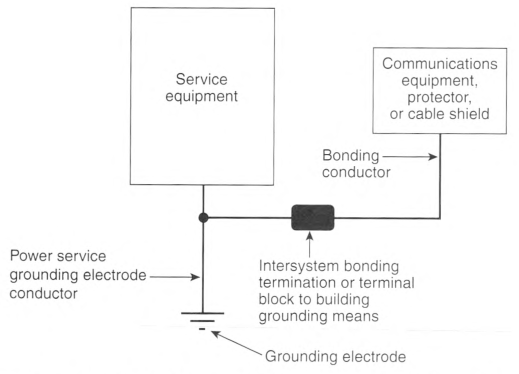
Informational Note: Informational Note Figure 800.100(B)(1) illustrates the connection of the bonding conductor in buildings or structures equipped with an intersystem bonding termination or a terminal block providing access to the building grounding means.
(2) In Buildings or Structures With Grounding Means.
If an intersystem bonding termination is established, 250.94(A) shall apply. If the building or structure served has no intersystem bonding termination, the bonding conductor or grounding electrode conductor shall be connected to the nearest accessible location on one of the following: 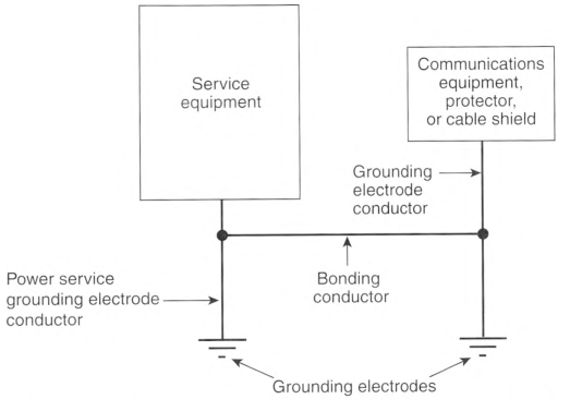
- The building or structure grounding electrode system as covered in 250.50
- The power service accessible means external to enclosures using the options identified in 250.94(A), Exception
- The nonflexible metal power service raceway
- The service equipment enclosure
- The grounding electrode conductor or the grounding electrode conductor metal enclosure of the power service
- The grounding electrode conductor or the grounding electrode of a building or structure disconnecting means that is connected to a grounding electrode as covered in 250.32
- The grounded interior metal water piping system, within 1.5 m (5 ft) from its point of entrance to the building, as covered in 250.52
A bonding device intended to provide a termination point for the bonding conductor (intersystem bonding) shall not interfere with the opening of an equipment enclosure. A bonding device shall be mounted on nonremovable parts. A bonding device shall not be mounted on a door or cover even if the door or cover is nonremovable.
For purposes of this section, the mobile home service equipment or the mobile home disconnecting means located within 9.0 m (30 ft) of the exterior wall of the mobile home it serves, or at a mobile home disconnecting means connected to an electrode by a grounding electrode conductor in accordance with 250.32 and located within 9.0 m (30 ft) of the exterior wall of the mobile home it serves, shall be considered to meet the requirements of this section.
Informational Note: See Informational Note Figure 800.100(B)(2) for an illustration of a grounding electrode conductor and a bonding conductor in a communications installation not equipped with an intersystem bonding termination or terminal block.
Informational Note Figure 800.100(B)(2) Illustration of a Grounding Electrode Conductor and a Bonding Conductor in a Communications Installation Not Equipped with an Intersystem Bonding Termination or Terminal Block Providing Access to the Building Grounding Means.
(3) In Buildings or Structures Without an Intersystem Bonding Termination or Grounding Means.
If the building or structure served has no intersystem bonding termination or grounding means, as described in 800.100(B)(2), the grounding electrode conductor shall be connected to one of the following:
- To any one of the individual grounding electrodes described in 250.52(A)(1), (A)(2), (A)(3), or (A)(4)
- If the building or structure served has no intersystem bonding termination or grounding means, as described in 800.100(B)(2) or (B)(3)(1), to any one of the individual grounding electrodes described in 250.52(A)(5), (A)(7), and (A)(8)
- For communications circuits covered in Article 805 or network-powered broadband communications systems covered in Article 830, to a ground rod or pipe not less than 1.5 m (5 ft) in length and 12.7 mm (0.5 in.) in diameter, driven, where practicable, into permanently damp earth and separated from lightning protection system conductors, as covered in 800.53, and at least 1.8 m (6 ft) from electrodes of other systems
Steam pipes, hot water pipes, or lightning protection system conductors shall not be employed as grounding electrodes or as a bonding or grounding electrode conductor for protectors and grounded metal members.
(D) Bonding of Electrodes.
A bonding jumper not smaller than 6 AWG copper or equivalent shall be connected between the grounding electrode and power grounding electrode system at the building or structure served if separate electrodes are used.
Exception: Bonding of electrodes at mobile homes shall be in accordance with 800.106.
Informational Note No. 1: See 250.60 for connection to a lightning protection system.
Informational Note No. 2: Bonding together of all separate electrodes limits potential differences between them and between their associated wiring systems.
800.106 Primary Protector Grounding and Bonding at Mobile Homes.
(A) Grounding.
(1) Mobile Home Service Equipment.
Where there is no mobile home service equipment located within 9.0 m (30 ft) of the exterior wall of the mobile home it serves, grounding shall comply with one of the following:
- The following components (if present) shall be connected to a grounding electrode in accordance with 800.100(B)(3):
- Primary protector grounding terminal
- Network interface unit
- Coaxial cable shield ground
- Surge arrester grounding terminal
- Network-powered broadband communications cable shield
- Network-powered broadband communications cable metal members not used for communications or powering
- The non-current-carrying metal members of optical fiber cables shall be connected to a grounding electrode in accordance with 770.106(A)(1). The network terminal, if required to be grounded, shall be connected to a grounding electrode in accordance with 800.106(A)(1)(1). The grounding electrode shall be bonded in accordance with 770.106(B).
(2) Mobile Home Feeder Disconnecting Means.
Where there is no mobile home disconnecting means grounded in accordance with 250.32 and located within 9.0 m (30 ft) of the exterior wall of the mobile home it serves, grounding shall comply with one of the following:
- The following components (if present) shall be connected to a grounding electrode in accordance with 800.100(B)(3):
- Primary protector grounding terminal
- Network interface unit
- Network-powered broadband communications shield
- Network-powered broadband communications cable metal members not used for communications or powering
- The non-current-carrying metal members of optical fiber cables shall be connected to a grounding electrode in accordance with 770.106(A)(2). The network terminal, if required to be grounded, shall be connected to a grounding electrode in accordance with 800.106(A)(2). The grounding electrode shall be bonded in accordance with 770.106(B).
(B) Bonding.
The primary protector grounding terminal or grounding electrode, network-powered broadband communications cable grounding terminal, or network interface unit grounding terminal shall be bonded together and connected to the metal frame or available grounding terminal of the mobile home with a copper conductor not smaller than 12 AWG under either of the following conditions:
- If there is no mobile home service equipment or disconnecting means as in 800.106(A)
- If the mobile home is supplied by cord and plug
800.110 Raceways, Cable Routing Assemblies, and Cable Trays.
(A) Types of Raceways.
Wires and cables shall be permitted to be installed in raceways that comply with 800.110(A)(1), 800.110(A)(2), or 800.110(A)(3). Medium-power network-powered broadband communications cables shall not be installed in raceways that comply with 800.110(A)(2).
(2) Communications Raceways.
Wires and cables shall be permitted to be installed in plenum communications raceways, riser communications raceways, and general-purpose communications raceways selected in accordance with Table 800.154(b), listed in accordance with 800.182, and installed in accordance with 800.113 and 362.24 through 362.56, where the requirements applicable to electrical nonmetallic tubing (ENT) apply.
(C) Cable Routing Assemblies.
Cables shall be permitted to be installed in plenum cable routing assemblies, riser cable routing assemblies, and general-purpose cable routing assemblies selected in accordance with Table 800.154(c), listed in accordance with 800.182, and installed in accordance with 800.110(C)(1) and (C)(2) and 800.113.
(1) Horizontal Support.
Cable routing assemblies shall be supported where run horizontally at intervals not to exceed 900 mm (3 ft) and at each end or joint, unless listed for other support intervals. In no case shall the distance between supports exceed 3 m (10 ft).
(2) Vertical Support.
Vertical runs of cable routing assemblies shall be supported at intervals not exceeding 1.2 m (4 ft), unless listed for other support intervals, and shall not have more than one joint between supports.
(D) Cable Trays.
Wires and cables and communications raceways shall be permitted to be installed in metal or listed nonmetallic cable tray systems. Ladder cable trays shall be permitted to support cable routing assemblies.
800.113 Installation of Cables Used for Communications Circuits, Communications Wires, Cable Routing Assemblies, and Communications Raceways.
Installation of wires, cables, cable routing assemblies, and communications raceways shall comply with 800.113(A) through (L). Installation of cable routing assemblies and communications raceways shall comply also with 800.110. Types of cables used by this section are identified in Table 800.113.
Table 800.113 Cables Used for Communications Circuits.
| Listed Cable Types | |
|---|---|
| Plenum cables | CMP, CATVP, BLP, OFNP, OFCP |
| Riser cables | CMR, CATVR, BMR, BLR, OFNR, OFCR |
| General-purpose cables | CMG, CM, CATV, BM, BL, OFNG, OFN, OFCG, OFC |
| Limited-use cables | CMX, CATVX, BLX |
| Undercarpet | CMUC |
| Underground | BMU, BLU |
(A) Listing.
Cables used for communications circuits, communications wires, cable routing assemblies, and communications raceways installed in buildings shall be listed and installed in accordance with the limitations of the listing.
Exception: Cables installed in compliance with 800.48 shall not be required to be listed.
(B) Ducts Specifically Fabricated for Environmental Air.
Installations of cables used for communications circuits, communications wires, cable routing assemblies, and communications raceways in ducts specifically fabricated for environmental air shall be in accordance with 800.113(B)(1) and (B)(2).
(1) Uses Permitted.
The following cables shall be permitted in ducts specifically fabricated for environmental air as described in 300.22(B) if they are directly associated with the air distribution system:
(2) Uses Not Permitted.
The following cables, wires, cable routing assemblies, and communications raceways shall not be permitted in ducts specifically fabricated for environmental air as described in 300.22(B):
- Plenum, riser, and general-purpose communications raceways
- Plenum, riser, and general-purpose cable routing assemblies
- Riser, general-purpose, and limited-use cables
- Type CMUC cables and wires
- Types BMU and BLU cables
- Communications wires
- Hybrid power and communications cables
Informational Note: See NFPA 90A-2021, Standard for the Installation of Air-Conditioning and Ventilating Systems, for information on fire protection of wiring installed in fabricated ducts.
(C) Other Spaces Used for Environmental Air (Plenums).
Installations of cables used for communications circuits, communications wires, cable routing assemblies, and communications raceways in other spaces used for environmental air (plenums) shall be in accordance with 800.113(C)(1) and (C)(2).
(1) Uses Permitted.
The following cables, wires, cable routing assemblies, and communications raceways shall be permitted in other spaces used for environmental air as described in 300.22(C):
- Plenum cables
- Plenum communications raceways
- Plenum cable routing assemblies
- Plenum cables installed in plenum communications raceways
- Plenum cables installed in plenum cable routing assemblies
- Plenum cables and plenum communications raceways supported by open metal cable tray systems
- Plenum, riser, general-purpose, and limited-use cables, and communications wires installed in raceways that are installed in compliance with 300.22(C)
- Plenum, rise, general-purpose, limited-use cables and plenum, riser, and general-purpose communications raceways supported by solid bottom metal cable trays with solid metal covers in other spaces used for environmental air (plenums) as described in 300.22(C)
- Plenum, riser, general-purpose, and limited-use cables installed in plenum, riser, and general-purpose communications raceways supported by solid bottom metal cable trays with solid metal covers in other spaces used for environmental air (plenums) as described in 300.22(C)
(2) Uses Not Permitted.
The following cables, wires, cable routing assemblies, and communications raceways shall not be permitted in other spaces used for environmental air as described in 300.22(C):
- Riser, general-purpose, and limited-use cables
- Riser and general-purpose communications raceways
- Riser and general-purpose cable routing assemblies
- Type CMUC cables and wires
- Types BMR, BM, BMU, and BLU cables
- Communications wires
- Hybrid power and communications cables
Informational Note: See NFPA 90A-2021, Standard for the Installation of Air-Conditioning and Ventilating Systems, for information on fire protection of wiring installed in other spaces used for environmental air.
(D) Risers - Cables, Cable Routing Assemblies, and Communications Raceways in Vertical Runs.
Installations of cables used for communications circuits, communications wires, cable routing assemblies, and communications raceways in risers shall be in accordance with 800.113(D)(1) and (D)(2).
(1) Uses Permitted.
The following cables, cable routing assemblies, and communications raceways shall be permitted in vertical runs penetrating one or more floors and in vertical runs in a shaft:
- Plenum and riser cables
- Plenum and riser communications raceways
- Plenum and riser cable routing assemblies
- Plenum and riser cables installed in the following:
- Plenum communications raceways
- Riser communications raceways
- Plenum cable routing assemblies
- Riser cable routing assemblies
(2) Uses Not Permitted.
The following cables, wires, cable routing assemblies, and communications raceways shall not be permitted in risers:
- General-purpose and limited-use cables
- General-purpose communications raceways
- General-purpose cable routing assemblies
- Type CMUC cables and wires
- Types BMR, BM, BMU, and BLU cables
- Communications wires
- Hybrid power and communications cables
Informational Note: See 800.26 for firestop requirements for floor penetrations.
(E) Risers — Cables and Innerducts in Metal Raceways.
Installations of cables used for communications circuits, communications wires, cable routing assemblies, and communications raceways in metal raceways in a riser having firestops at each floor shall be in accordance with 800.113(E)(1) and (E)(2).
(1) Uses Permitted.
The following cables and innerducts shall be permitted in metal raceways in a riser having firestops at each floor:
(2) Uses Not Permitted.
The following cables, wires, cable routing assemblies, and communications raceways shall not be permitted in metal raceways in a riser having firestops at each floor:
- Plenum, riser, and general-purpose cable routing assemblies
- Type CMUC cables and wires
- Types BMR. BM, BMU, and BLU cables
- Communications wires
- Hybrid power and communications cables
Informational Note: See 800.26 for firestop requirements for floor penetrations.
(F) Risers — Cables, Cable Routing Assemblies, and Communications Raceways in Fireproof Shafts.
Installations of cables used for communications circuits, communications wires, cable routing assemblies, and communications raceways in fireproof riser shafts having firestops at each floor shall be in accordance with 800.113(F)(1) and (F)(2).
(1) Uses Permitted.
The following cables, cable routing assemblies, and communications raceways shall be permitted to be installed in fireproof riser shafts having firestops at each floor:
- Plenum, riser, general-purpose, and limited-use cables
- Plenum, riser, and general-purpose communications raceways
- Plenum, riser, and general-purpose cable routing assemblies
- Plenum, riser, general-purpose, and limited-use cables installed in the following:
- Plenum communications raceways
- Riser communications raceways
- General-purpose communications raceways
- Plenum cable routing assemblies
- Riser cable routing assemblies
- General-purpose cable routing assemblies
(2) Uses Not Permitted.
The following cables, wires, cable routing assemblies, and communications raceways shall not be permitted in metal raceways in fireproof riser shafts having firestops at each floor:
- Type CMUC cables and wires
- Type BMU and BLU cables
- Communications wires
- Hybrid power and communications cables
Informational Note: See 800.26 for firestop requirements for floor penetrations.
(G) Risers — One- And Two-Family Dwellings.
Installations of cables used for communications circuits, communications wires, cable routing assemblies, and communications raceways in risers in one- and two-family dwellings shafts shall be in accordance with 800.113(G)(1) and (G)(2).
(1) Uses Permitted.
The following cables, cable routing assemblies, and communications raceways shall be permitted in one- and two-family dwellings:
- Plenum, riser, and general-purpose cables
- Limited-use cables less than 6 mm (0.25 in.) in diameter
- Plenum, riser, and general-purpose communications raceways
- Plenum, riser, and general-purpose cable routing assemblies
- Plenum, riser, and general-purpose cables installed in the following:
- Plenum communications raceways
- Riser communications raceways
- General-purpose communications raceways
- Plenum cable routing assemblies
- Riser cable routing assemblies
- General-purpose cable routing assemblies
(H) Cable Trays.
Installations of cables used for communications circuits, communications wires, cable routing assemblies, and communications raceways supported by cable trays shall be in accordance with 800.113(H)(1) and (H)(2).
(1) Uses Permitted.
(I) Distributing Frames and Cross-Connect Arrays.
Installations of cables used for communications circuits, communications wires, cable routing assemblies, and communications raceways in distributing frames and cross-connect arrays shall be in accordance with 800.113(I)(1) and (I)(2).
(1) Uses Permitted.
The following wires, cables, cable routing assemblies, and communications raceways shall be permitted to be installed in distributing frames and cross-connect arrays:
- Plenum, riser, and general-purpose cables and communications wires
- Plenum, riser, and general-purpose communications raceways
- Plenum, riser, and general-purpose cable routing assemblies
- Plenum communications raceways
- Riser communications raceways
- General-purpose communications raceways
- Plenum cable routing assemblies
- Riser cable routing assemblies
- General-purpose cable routing assemblies
(J) Other Building Locations.
Installations of cables used for communications circuits, cable communications wires, routing assemblies, and communications raceways in building locations other than those covered in 800.113(B) through (I) shall be in accordance with 800.113 (J)(1) and (J)(2).
(1) Uses Permitted.
The following wires, cables, cable routing assemblies, and communications raceways shall be permitted to be installed in building locations other than the locations covered in 800.113(B) through (I):
- Plenum, riser, and general-purpose cables
- Limited-use cables with a maximum of 3 m (10 ft) of exposed length in nonconcealed spaces
- Plenum, riser, and general-purpose communications raceways
- Plenum, riser, and general-purpose cable routing assemblies
- Plenum, riser, and general-purpose cables installed in the following:
- Plenum cable routing assemblies
- Riser cable routing assemblies
- General-purpose cable routing assemblies
- Communications wires and plenum, riser, general-purpose, and limited-use cables installed in raceways recognized in Chapter 3
- Type CMUC undercarpet communications wires and cables installed under carpet, modular flooring, and planks
(2) Uses Not Permitted.
The following cables, wires, cable routing assemblies, and communications raceways shall not be installed in building locations other than the locations covered in 800.113(B) through (I):
- Types BMU and BLU cables
- Communications wires
- Hybrid power and communications cables
(K) Multifamily Dwellings.
Installations of cables used for communications circuits, communications wires, cable routing assemblies, and communications raceways in multifamily dwellings shall be in accordance with 800.113(K)(1) and (K)(2).
(1) Uses Permitted.
The following cables, cable routing assemblies, and communications raceways shall be permitted to be installed in multifamily dwellings in locations other than the locations covered in 800.113(B) through (G):
- Plenum, riser, and general-purpose cables
- Limited-use cables less than 6 mm (0.25 in.) in diameter in nonconcealed spaces
- Plenum, riser, and general-purpose communications raceways
- Plenum, riser, and general-purpose cable routing assemblies
- Plenum, riser, and general-purpose cables installed in the following:
- Plenum cable routing assemblies
- Riser cable routing assemblies
- General-purpose cable routing assemblies
- Communications wires and plenum, riser, general-purpose, and limited-use cables installed in raceways recognized in Chapter 3
- Type CMUC under-carpet communications wires and cables installed under carpet, modular flooring, and planks
(2) Uses Not Permitted.
The following cables, cable routing assemblies, and communications raceways shall not be installed in multifamily dwellings in locations other than the locations covered in 800.113(B) through (G):
- Types BMU and BLU cables
- Communications wires
- Hybrid power and communications cables
(L) One- And Two-Family Dwellings.
Installations of cables used for communications circuits, communications wires, cable routing assemblies, and communications raceways in one- and two-family dwellings in locations other than those covered in 800.113(B) through (F) shall be in accordance with 800.113(L)(1) and (L)(2).
(1) Uses Permitted.
The following wires, cables, cable routing assemblies, and communications raceways shall be permitted to be installed in one- and two-family dwellings in locations other than the locations covered in 800.113(B) through (F):
- Plenum, riser, and general-purpose cables
- Limited-use cables less than 6 mm (0.25 in.) in diameter
- Plenum, riser, and general-purpose communications raceways
- Plenum, riser, and general-purpose cable routing assemblies
- Plenum, riser, and general-purpose cables installed in the following:
- Plenum cable routing assemblies
- Riser cable routing assemblies
- General-purpose cable routing assemblies
- Communications wires and plenum, riser, general-purpose, and limited-use cables installed in raceways recognized in Chapter 3
- Type CMUC under-carpet communications wires and cables installed under carpet, modular flooring, and planks
- Hybrid power and communications cable listed in accordance with 800.179
(2) Uses Not Permitted.
The following cables, wires, cable routing assemblies, and communications raceways shall not be installed in one- and two-family dwellings in locations other than those covered in 800.113(B) through (F):
- Types BMU and BLU cables
- Communications wires
800.133 Installation of Communications Wires and Cables and CATV-type Coaxial Cables.
Installation of communications wires and cables, from the protector to the equipment, or where no protector is required, communications wires and cables attached to the outside or inside of the building, shall comply with 800.133(A) and 800.133(B). Installation of CATV-type coaxial cables, beyond the point of grounding as defined in 820.93, shall comply with 800.133(A) through (C).
(A) In Raceways, Cable Trays, Boxes, Cables, Enclosures, and Cable Routing Assemblies.
(1) Other Circuits.
Communications cables and CATV-type coaxial cables shall be permitted in the same raceway, cable tray, box, enclosure, or cable routing assembly together and with jacketed cables of any of the following:
- Class 2 and Class 3 remote-control, signaling, and power-limited circuits in compliance with 645.5(E)(2) or Parts I and II of Article 725
- Power-limited fire alarm systems in compliance with Parts I and III of Article 760
- Nonconductive and conductive optical fiber cables in compliance with Parts I and V of Article 770
- Communications circuits in compliance with Parts I and IV of Articles 800 and 805
- Community antenna television and radio distribution systems in compliance with Parts I and V of Articles 800 and 820
- Low-power network-powered broadband communications circuits in compliance with Parts I and V of Articles 800 and 830
(2) Class 2 and Class 3 Circuits.
Class 1 circuits shall not be run in the same cable with communications circuits. Class 2 and Class 3 circuit conductors shall be permitted in the same listed communications cable with communications circuits.
(3) Electric Light, Power, Class 1, Non-Power-Limited Fire Alarm, and Medium-Power Network-Powered Broadband Communications Circuits in Raceways, Compartments, and Boxes.
Communications wires and cables and CATV-type coaxial cables shall not be placed in any raceway, compartment, outlet box, junction box, or similar fitting with conductors of electric light, power, Class 1, non-power-limited fire alarm, or medium-power network-powered broadband communications circuits.
Exception No. 1: Communications wires and cables and CATV-type coaxial cables shall be permitted to be placed in any raceway, compartment, outlet box, junction box, or other enclosures with conductors of electric light, power, Class 1, non-power-limited fire alarm., or medium-power network-powered broadband communications circuits where all of the conductors of electric light, power, Class 1, non-power-limited fire alarm, and medium-power network-powered broadband communications circuits are separated from all of the communications wires and cables and CATV-type coaxial cables by a permanent barrier or listed divider.
Exception No. 2: Communications wires and cables and CATV-type coaxial cables shall be permitted to be placed in outlet boxes, junction boxes, or similar fittings or compartments with power conductors where such conductors are introduced solely for power supply to the communications and coaxial cable system distribution equipment. The power circuit conductors shall be routed within the enclosure to maintain a minimum 6 mm (1/4 in.) separation from the communications wires and cables and the CATV-type coaxial cables.
Exception No. 3: Separation of circuits shall not be required in elevator traveling cables constructed in accordance with by 620.36.
(B) Other Applications.
Communications wires and cables and CATV-type coaxial cables shall be separated at least 50 mm (2 in.) from conductors of any electric light, power, Class 1, non—power-limited fire alarm, or medium-power network-powered broadband communications circuits.
Exception No. 1: Separation shall not be required where either (1) all of the conductors of electric light, power, Class 1, non-power-limited fire alarm, and medium-power network-powered broadband communications circuits are in a raceway or in metal-sheathed, metal-clad, nonmetallic-sheathed, Type AC or Type UF cables, or (2) all of the communications wires and cables and all of the CATV-type coaxial cables are encased in raceway.
Exception No. 2: Separation shall not be required where the communications wires and cables and CATV-type coaxial cables are permanently separated from the conductors of electric light, power, Class 1, non-power-limited fire alarm, and medium-power network-powered broadband communications circuits by a continuous and firmly fixed nonconductor, such as porcelain lubes or flexible tubing, in addition to the insulation on the wire.
(C) Support of Communications Wires and Cables and CATV-type Coaxial Cables.
800.154 Applications of Listed Communications Wires, Cables, and Raceways, and Listed Cable Routing Assemblies.
Permitted and nonpermitted applications of listed communications wires, cables, coaxial cables, network-powered broadband communications system cables and raceways, and listed cable routing assemblies, shall be in accordance with one of the following:
- Listed communications wires and cables as indicated in Table 800.154(a)
- Listed communications raceways as indicated in Table 800.154(b)
- Listed cable routing assemblies as indicated in Table 800.154(c)
Table 800.154(a) Applications of Listed Communications Wires, Cables, and Network-Powered Broadband Communications System Cables in Buildings.
| Applications | Wire and Cable Type | ||||||||||
|---|---|---|---|---|---|---|---|---|---|---|---|
| Plenum | Riser | BMR | General-Purpose | BM | Limited-Use | Undercarpet | BMU, BLU | Hybrid Power and Communications Cables | Communications Wires | ||
| In ducts specifically fabricated for environmental air as described in 300.22(B) | In fabricated ducts | Y | N | N | N | N | N | N | N | N | N |
| In metal raceway that complies with 300.22(B) | Y | Y | Y | Y | Y | Y | N | N | N | Y | |
| In other spaces used for environmental air (plenums) as described in 300.22(C) | In other spaces used for environmental air | Y | N | N | N | N | N | N | N | N | N |
| In metal raceway that complies with 300.22(C) | Y | Y | Y | Y | Y | Y | N | N | N | Y | |
| In plenum communications raceways | Y | N | N | N | N | N | N | N | N | N | |
| In plenum cable routing assemblies | Y | N | N | N | N | N | N | N | N | N | |
| Supported by open metal cable trays | Y | N | N | N | N | N | N | N | N | N | |
| Supported by solid bottom metal cable trays with solid metal covers | Y | Y | Y | Y | Y | Y | N | N | N | N | |
| In risers | In vertical runs | Y | Y | Y | N | N | N | N | N | N | N |
| In metal raceways | Y | Y | Y | Y | Y | Y | N | N | N | N | |
| In fireproof shafts | Y | Y | Y | Y | Y | Y | N | N | N | N | |
| In plenum communications raceways | Y | Y | N | N | N | N | N | N | N | N | |
| In plenum cable routing assemblies | Y | Y | N | N | N | N | N | N | N | N | |
| In riser communications raceways | Y | Y | N | N | N | N | N | N | N | N | |
| In riser cable routing assemblies | Y | Y | N | N | N | N | N | N | N | N | |
| In one- and two- family dwellings | Y | Y | Y | Y | Y | Y | N | N | Y | N | |
| Within buildings in other than air-handling spaces and risers | General | Y | Y | Y | Y | Y | Y | N | N | N | N |
| In one- and two- family dwellings | Y | Y | Y | Y | Y | Y | Y | N | Y | N | |
| In multifamily dwellings | Y | Y | Y | Y | Y | Y | Y | N | N | N | |
| In nonconcealed spaces | Y | Y | Y | Y | Y | Y | Y | N | N | N | |
| Supported by cable trays | Y | Y | Y | Y | Y | N | N | N | N | N | |
| Under carpet, modular flooring, and planks | N | N | N | N | N | N | Y | N | N | N | |
| In distributing frames and cross-connect arrays | Y | Y | N | Y | N | N | N | N | N | Y | |
| In rigid metal conduit (RMC) and intermediate metal conduit (IMC) | Y | Y | Y | Y | Y | Y | Y | Y | Y | Y | |
| In any raceway recognized in Chapter 3 | Y | Y | Y | Y | Y | Y | N | N | N | Y | |
| In plenum communications raceways | Y | Y | N | Y | N | N | N | N | N | Y | |
| In plenum cable routing assemblies | Y | Y | N | Y | N | N | N | N | N | Y | |
| In riser communications raceways | Y | Y | N | Y | N | N | N | N | N | Y | |
| In riser cable routing assemblies | Y | Y | N | Y | N | N | N | N | N | Y | |
| In general-purpose communications raceways | Y | Y | N | Y | N | N | N | N | N | Y | |
| In general-purpose cable routing assemblies | Y | Y | N | Y | N | N | N | N | N | Y | |
Note: An "N" in the table indicates that the cable type shall not be installed in the application. A "Y" indicates that the cable type shall be permitted to be installed in the application subject to the limitations described in 800.113. The Riser column includes all riser cables except BMR, and the General-Purpose column includes all general-purpose cables except BM.
Table 800.154(b) Applications of Listed Communications Raceways in Buildings.
| Applications | Listed Communications Raceway Type | |||
|---|---|---|---|---|
| Plenum | Riser | General-Purpose | ||
| In ducts specifically fabricated for environmental air as described in 300.22(B) | In fabricated ducts | N | N | N |
| In metal raceway that complies with 300.22(B) | N | N | N | |
| In other spaces used for environmental air (plenums) as described in 300.22(C) | In other spaces used for environmental air | Y | N | N |
| In metal raceway that complies with 300.22(C) | Y | Y | Y | |
| In plenum cable routing assemblies | N | N | N | |
| Supported by open metal cable trays | Y | N | N | |
| Supported by solid bottom metal cable trays with solid metal covers | Y | Y | Y | |
| In risers | In vertical runs | Y | Y | N |
| In metal raceways | Y | Y | Y | |
| In fireproof shafts | Y | Y | Y | |
| In plenum cable routing assemblies | N | N | N | |
| In riser cable routing assemblies | N | N | N | |
| In one- and two-family dwellings | Y | Y | Y | |
| Within buildings in other than air-handling spaces and risers | General | Y | Y | Y |
| In one- and two-family dwellings | Y | Y | Y | |
| In multifamily dwellings | Y | Y | Y | |
| In nonconcealed spaces | Y | Y | Y | |
| Supported by cable trays | Y | Y | Y | |
| Under carpet, modular flooring, and planks | N | N | N | |
| In distributing frames and cross-connect arrays | Y | Y | Y | |
| In any raceway recognized in Chapter 3 | Y | Y | Y | |
| In plenum cable routing assemblies | N | N | N | |
| In riser cable routing assemblies | N | N | N | |
| In general-purpose cable routing assemblies | N | N | N | |
Table 800.154(c) Applications of Listed Cable Routing Assemblies in Buildings.
| Applications | Listed Cable Routing Assembly Type | |||
|---|---|---|---|---|
| Plenum | Riser | General-Purpose | ||
| In ducts specifically fabricated for environmental air as described in 300.22(B) | In fabricated ducts | N | N | N |
| In metal raceway that complies with 300.22(B) | N | N | N | |
| In other spaces used for environmental air (plenums) as described in 300.22(C) | In other spaces used for environmental air | Y | N | N |
| In metal raceway that complies with 300.22(C) | N | N | N | |
| In plenum communications raceways | N | N | N | |
| Supported by open metal cable trays | Y | N | N | |
| Supported by solid bottom metal cable trays with solid metal covers | N | N | N | |
| In risers | In vertical runs | Y | Y | N |
| In metal raceways | N | N | N | |
| In fireproof shafts | Y | Y | Y | |
| In plenum communications raceways | N | N | N | |
| In riser communications raceways | N | N | N | |
| In one- and two-family dwellings | Y | Y | Y | |
| Within buildings in other than air-handling spaces and risers | General | Y | Y | Y |
| In one- and two-family dwellings | Y | Y | Y | |
| In multifamily dwellings | Y | Y | Y | |
| In nonconcealed spaces | Y | Y | Y | |
| Supported by cable trays | Y | Y | Y | |
| Under carpet, modular flooring, and planks | N | N | N | |
| In distributing frames and cross-connect arrays | Y | Y | Y | |
| In any raceway recognized in Chapter 3 | N | N | N | |
| In plenum communications raceways | N | N | N | |
| In riser communications raceways | N | N | N | |
| In general-purpose communications raceways | N | N | N | |
Note: An "N" in the table indicates that the cable routing assembly type shall not be installed in the application. A "Y" indicates that the cable routing assembly type shall be permitted to be installed in the application subject to the limitations described in 800.113.
Informational Note No. 1: Part IV of Article 800 covers installation methods within buildings. This table covers the applications of listed communications wires, cables, and raceways in buildings.
Informational Note No. 2: For information on the restrictions to the installation of communications cables in fabricated ducts, see 800.113(B).
800.170 Plenum Cable Ties.
Cable lies intended for use in other space used for environmental air (plenums) shall be listed as having low smoke and heat release properties.
Informational Note: See NFPA 90A-2018, Standard for the Installation of Air-Conditioning and Ventilating Systems, and ANSI/ UL 2043-2013, Standard for Safety Tire Test for Heat and Visible Smoke Release for Discrete Products and Their Accessories Installed in Air-Handling Spaces, for information on listing discrete products as having low smoke and heat release properties.
800.171 Communications Equipment.
Communications equipment shall be listed as being suitable for electrical connection to a communications network.
Informational Note No. 1: See ANSI/UL 60950-1-2014, Standard for Safety of Information Technology Equipment, ANSI/ UL 1863-2012, Standard for Safety Communications Circuit Accessories, or ANSI/UL 62368-1-2014 or ANSI/UL 62368-1-2018, Audio/Video, Information and Communication Technology Equipment - Part 1: Safety Requirements.
Informational Note No. 2: See ANSI/ATIS 0600337-2016, Requirements for Maximum Voltage, Current, and Power Levels Used in Communications Circuits, for additional information regarding voltages, currents, and power allowed on communications circuits.
800.179 Wires and Cables.
Communications wires and cables, community antenna television cables, and network-powered broadband communications cables shall be listed in accordance with 800.179(A) through (L) and shall have a temperature rating of not less than 60°C (140°F). The temperature rating shall be marked on the jacket of cables that have a temperature rating exceeding 60°C (140°F). Conductors in communications cables, other than in a coaxial cable, shall be copper. Cables shall be permitted to contain optical fibers. Cables containing optical fibers shall be marked with the suffix "-OF."
Communications wires and cables and network-powered communications cables shall have a voltage rating of not less than 300 volts; the insulation for the individual conductors, other than the outer conductor of a coaxial cable, shall be rated for 300 volts minimum. The cable voltage rating shall not be marked on the cable or on the under-carpet communications wire.
Exception: Voltage markings shall be permitted where the cable has multiple listings and voltage marking is required for one or more of the listings.
Informational Note No. 1: Voltage markings on cables could be misinterpreted to suggest that the cables may be suitable for Class 1, electric light, and power applications.
Informational Note No. 2: See UL 444-2017, Standard for Communications Cables, for information on communications cables.
Informational Note No. 3: See UL1655-2009, Standard for Community-Antenna Television Cables, for information on community-antenna television cables.
(A) Plenum Cables.
Type CMP communications plenum cables, Type CATVP community antenna television plenum coaxial cables, and Type BLP network-powered broadband communication low-power plenum cables shall be listed as being suitable for use in ducts, plenums, and other spaces used for environmental air and shall also be listed as having adequate fire-resistant and low-smoke-producing characteristics.
Informational Note: See NFPA 262-2019, Standard Method of Test for Flame Travel and Smoke of Wires and Cables for Use in Air-Handling Spaces, for one method of defining a cable that is low-smoke-producing cable and fire-resistant cable so that the cable exhibits a maximum peak optical density of 0.50 or less, an average optical density of 0.15 or less, and a maximum flame spread distance of 1.52 m (5 ft).
(B) Riser Cables.
Type CMR communications riser cables, Type CATVR community antenna television riser coaxial cables, Type BMR network-powered broadband communications medium-power riser cables, and Type BLR network-powered broadband communications low-power riser cables shall be listed as being suitable for use in a vertical run in a shaft or from floor to floor and shall also be listed as having fire-resistant characteristics capable of preventing the carrying of fire from floor to floor.
(C) General-Purpose Cables.
(1) Type CMG.
Type CMG communications general-purpose cables shall be listed as being suitable for general-purpose use, with the exception of risers and plenums, and shall also be listed as being resistant to the spread of fire.
Informational Note: See CSA Vertical Flame Test - Cables in Cable Trays as described in CSA C22.2 No. 0.3-09 (R2019), Test Methods for Electrical Wires and Cables, for one method of defining resistance to the spread of fire where the damage (char length) of the cable does not exceed 1.5 m (4 ft 11 in.) or FT4 Flame Test in ANSI/UL 1685-2015, Standard for Safety for Vertical-Tray Fire-Propagation and Smoke-Release Test for Electrical and Optical-Fiber Cables. The smoke measurements in the test methods are not applicable.
(2) Types cm, CATV, BM, and BL.
Type CM communications general-purpose cables, Type CATV community antenna television coaxial general-purpose cables, Type BM network-powered broadband communications medium-power general-purpose cables, and Type BL network-powered broadband communications low-power general-purpose cables shall be listed as being suitable for general-purpose use, with the exception of risers and plenums, and shall also be listed as being resistant to the spread of fire.
Informational Note: See UL Flame Exposure in ANSI/ UL 1685-2015, Standard for Safety for Vertical-Tray Fire-Propagation and Smoke-Release Test for Electrical and Optical-Fiber Cables, for one method of defining resistance to the spread of fire where the damage (char length) of the cable does not to exceed 244 cm (8 ft 0 in.). The smoke measurements in the test method are not applicable.
(D) Limited-Use Cables.
Type CMX limited-use communications cables, Type CATVX limited-use community antenna television coaxial cables, and Type BLX limited-use network-powered broadband low-power cables shall be listed as being suitable for use in dwellings and for use in raceway and shall also be listed as being resistant to flame spread.
(E) Circuit Integrity (CI) Cable, Fire-Resistive Cable System, or Electrical Circuit Protective System.
Cables that are used for survivability of critical circuits under fire conditions shall be listed and meet either 800.179(E)(1), (E)(2), or (E)(3).
(1) CI Cables.
Cables specified in 800.179(A) through (C) and used for survivability of critical circuits shall be marked with the additional classification using the suffix "CI." In order to maintain its listed lire rating, CI cable shall only be installed in free air in accordance with 800.24. CI cables shall only be permitted to be installed in a raceway where specifically listed and marked as part of a fire-resistive cable system as covered in 800.179(E)(2).
Informational Note: See UL 2196, Standard for Fire Test for Circuit Integrity of Fire-Resistant Power, Instrumentation, Control, and Data Cables, for one method of defining CI cable by establishing a minimum 2-hour fire resistance rating for the cable as specified in UL 444, Standard for Safety Communications Cables.
(2) Fire-Resistive Cable Systems.
Cables specified in 800.179(A) through (C) and 800.179(E)(1) that are part of an electrical circuit protective system shall be fire-resistive cable identified with the protective system number on the product, or on the smallest unit container in which the product is packaged, and shall be installed in accordance with the listing of the protective system.
Informational Note No. 1: See UL 2196, Fire Test for Circuit Integrity of Fire-Resistive Power, Instrumentation, Control and Data Cables, for one method of defining an electrical circuit protective system rating for the system. UL Guide Information for Electrical Circuit Integrity Systems (FHIT) contains information to identify the system and its installation limitations to maintain a minimum fire-resistive rating.
Informational Note No. 2: The listing organization provides information for electrical circuit protective systems (FHIT), including installation requirements for maintaining the fire rating.
(3) Electrical Circuit Protective System.
Protectants for cables specified in 800.179(A) through (E), which are part of an electrical circuit protective system, shall be identified with the protective system identifier and hourly rating marked on the protectant or the smallest unit container and installed in accordance with the listing of the system.
Informational Note: See UL 1724, Fire Tests for Electrical Circuit Protective Systems, for one method of defining an electrical circuit protective system. UL Guide Information for Electrical Circuit Integrity Systems (FHIT) contains information to identify the system and its installation limitations to maintain the fire-resistive rating.
(F) Types CMP-LP, CMR-LP, CMG-LP, and CM-LP Limited Power (LP) Cables.
Types CMP-LP, CMR-LP, CMG-LP, and CM-LP communications limited power cables shall be listed as suitable for carrying power and data up to a specified current limit for each conductor without exceeding the temperature rating of the cable where the cable is installed in cable bundles in free air or installed within a raceway, cable tray, or cable routing assembly. The cables shall be marked with the suffix "-LP(XXA)," where XX designates the current limit in amperes per conductor.
(G) Type CMUC Undercarpet Wires and Cables.
Type CMUC undercarpet communications wires and cables shall be listed as being suitable for undercarpet use and shall also be listed as being resistant to flame spread.
(H) Communications Wires.
Communications wires, such as distributing frame wire and jumper wire, shall be listed as being resistant to the spread of fire.
Informational Note No. 1: See UL Flame Exposure, Vertical Flame Tray Test in ANSI/UL 1685-2015, Standard for Safety for Vertical-Tray Fire-Propagation and Smoke-Release lest for Electrical and Optical-Fiber Cables, for one method of defining cable flame resistance to the spread of fire where the cables do not spread fire to the top of the tray. The smoke measurements in the test method are not applicable.
Informational Note No. 2: See CSA Vertical Flame Test - Cables in Cable Trays, as described in CSA C22.2 No. 0.3-09 (R2019), Test Methods for Electrical Wires and Cables, for another method of defining resistance to the spread of fire is for the damage (char length) of the cable to not exceed 1.5 m (4 ft 11 in.).
(I) Optional Markings.
Cables shall be permitted to be surface marked to indicate special characteristics of the cable materials.
Informational Note: These markings can include, but are not limited to, markings for limited-smoke, halogen-free, low-smoke halogen-free, and sunlight resistance.
800.180 Grounding Devices.
Where bonding or grounding is required, devices used to connect a shield, a sheath, or noncurrent-carrying metallic members of a cable to a bonding conductor or grounding electrode conductor shall be listed or be part of listed equipment.
800.182 Cable Routing Assemblies and Communications Raceways.
Cable routing assemblies and communications raceways shall be listed in accordance with 800.182(A) through (C). Cable routing assemblies shall be marked in accordance with Table 800.182(a). Communications raceways shall be marked in accordance with Table 800.182(b).
Informational Note: See ANSI/UL 2024-5-2015, Cable Routing Assemblies and Communications Raceways, for information on listing requirements for both communications raceways and cable routing assemblies.
(A) Plenum Cable Routing Assemblies and Plenum Communications Raceways.
Plenum cable routing assemblies and plenum communications raceways shall be listed as having adequate fire-resistant and low-smoke-producing characteristics.
Informational Note No. 1: See ASTM E84-19B, Standard lest Method for Surface Burning Characteristics of Building Materials, or ANSI/UL 723-2018, Standard Test Method for Surface Burning Characteristics of Building Materials, for one method of defining cable routing assemblies and communications raceways that have adequate fire-resistant and low-smoke-producing characteristics and exhibit a maximum flame spread index of 25 and a maximum smoke developed index of 50.
Informational Note No. 2: See NFPA 262-2019, Standard Method of Test for Flame Travel and Smoke of Wires and Cables for Use in Air-Handling Spaces, for another method of defining communications raceways that have adequate fire-resistant and low-smoke-producing characteristics and exhibit a maximum peak optical density of 0.50 or less, an average optical density of 0.15 or less, and a maximum flame spread distance of 1.52 m (5 ft) or less.
Informational Note No. 3: See 4.3.11.2.6 or 4.3.11.5.5 of NFPA 90A-2021, Standard for the Installation of Air-Conditioning and Ventilating Systems, for information on materials exposed to the airflow in ceiling cavity and raised floor plenums.
Table 800.182(a) Cable Routing Assembly Markings.
| Type | Marking |
|---|---|
| Plenum Cable Routing Assembly | Plenum Cable Routing Assembly |
| Riser Cable Routing Assembly | Riser Cable Routing Assembly |
| General-Purpose Cable Routing Assembly | General-Purpose Cable Routing Assembly |
(B) Riser Cable Routing Assemblies and Riser Communications Raceways.
Riser cable routing assemblies and riser communications raceways shall be listed as having adequate fire-resistant characteristics capable of preventing the carrying of fire from floor to floor.
Informational Note: See ANSI/UL 1666-2017, Standard Test for Flame Propagation Height of Electrical and Optical Fiber Cable Installed Vertically in Shafts, for one method of defining fire-resistant characteristics capable of preventing the carrying of fire from floor to floor of the cable routing assemblies and communications raceways.
(C) General-Purpose Cable Routing Assemblies and General-Purpose Communications Raceways.
General-purpose cable routing assemblies and general-purpose communications raceways shall be listed as being resistant to the spread of fire.
Informational Note: See ANSI/UL 1685-2015, Standard for Safety for Vertical-Tray Fire-Propagation and Smoke-Release Test for Electrical and Optical-Fiber Cables, for one method of defining resistance to the spread of fire where the cable routing assemblies and communications raceways do not spread fire to the top of the tray.
Article 805
Communications Circuits
805.18 Installation of Equipment.
Equipment electrically connected to a communications network shall be listed in accordance with 800.171.
805.47 Underground Communications Wires and Cables Entering Buildings — Underground Block Distribution.
Where the entire street circuit is run underground and the circuit within the block is placed so as to be free from the likelihood of accidental contact with electric light or power circuits of over 300 volts to ground, the insulation requirements of 805.50(A) and 805.50(C) shall not apply, insulating supports shall not be required for the conductors, and bushings shall not be required where the conductors enter the building.
805.50 Circuits Requiring Primary Protectors.
Circuits that require primary protectors as provided in 805.90 shall comply with 805.50(A),805.50(B), and 805.50(C).
(B) On Buildings.
Communications wires and cables in accordance with 805.50(A) shall be separated at least 100 mm (4 in.) from electric light or power conductors not in a raceway or cable or be permanently separated from conductors of the other systems by a continuous and firmly fixed nonconductor in addition to the insulation on the wires, such as porcelain tubes or flexible tubing. Communications wires and cables in accordance with 805.50(A) exposed to accidental contact with electric light and power conductors operating at over 300 volts to ground and attached to buildings shall be separated from woodwork by being supported on glass, porcelain, or other insulating material.
Exception: Separation from woodwork shall not be required where fuses are omitted as provided for in 805.90(A)(1), or where conductors are used to extend circuits to a building from a cable having a grounded metal sheath.
(C) Entering Buildings.
(1) Installed Inside Buildings.
If a primary protector is installed inside the building, the communications wires and cables shall enter the building either through a noncombustible, nonabsorbent insulating bushing or through a metal raceway.
Exception: The insulating bushing shall not be required if the entering communications wires and cables meet one or more of the following conditions:
(1) Is a metal-sheathed cable
(2) Pass through masonry
805.90 Protective Devices.
(A) Application.
A listed primary protector shall be provided on each circuit run partly or entirely in aerial wire or aerial cable not confined within a block. Also, a listed primary protector shall be provided on each circuit, aerial or underground, located within the block containing the building served so as to be exposed to accidental contact with electric light or power conductors operating at over 300 volts to ground. In addition, where there exists a lightning exposure, each interbuilding circuit on a premises shall be protected by a listed primary protector at each end of the interbuilding circuit. Installation of primary protectors shall also comply with 110.3(B).
Informational Note No. 1: On a circuit not exposed to accidental contact with power conductors, providing a listed primary protector in accordance with this article helps protect against other hazards, such as lightning and above-normal voltages induced by fault currents on power circuits in proximity to the communications circuit.
Informational Note No. 2: Interbuilding circuits are considered to have a lightning exposure unless one or more of the following conditions exist:
- Circuits in large metropolitan areas where buildings are close together and sufficiently high to intercept lightning.
- Interbuilding cable runs of 42 m (140 ft) or less, directly buried or in underground conduit, where a continuous metallic cable shield or a continuous metal conduit containing the cable is connected to each building grounding electrode system.
- Areas having an average of five or fewer thunderstorm days per year and earth resistivity of less than 100 ohmmeters. Such areas are found along the Pacific coast.
Informational Note No. 3: See NFPA 780-2020, Standard for the Installation of Lightning Protection Systems, for information on lightning protection systems.
(1) Fuseless Primary Protectors.
Fuseless-type primary protectors shall be permitted under any of the following conditions:
- Where conductors enter a building through a cable with grounded metallic sheath member(s) and where the conductors in the cable safely fuse on all currents greater than the current-carrying capacity of the primary protector and of the primary protector bonding conductor or grounding electrode conductor
- Where insulated conductors in accordance with 805.50(A) are used to extend circuits to a building from a cable with an effectively grounded metallic sheath member(s) and where the conductors in the cable or cable stub, or the connections between the insulated conductors and the plant exposed to accidental contact with electric light or power conductors operating at greater than 300 volts to ground, safely fuse on all currents greater than the current-carrying capacity of the primary protector, or the associated insulated conductors and of the primary protector bonding conductor or grounding electrode conductor
- Where insulated conductors in accordance with 805.50(A) or (B) are used to extend circuits to a building from other than a cable with metallic sheath member(s), where (a) the primary protector is listed as being suitable for this purpose for application with circuits extending from other than a cable with metallic sheath members and (b) the connections of the insulated conductors to the plant exposed to accidental contact with electric light or power conductors operating at greater than 300 volts to ground or the conductors of the plant exposed to accidental contact with electric light or power conductors operating at greater than 300 volts to ground safely fuse on all currents greater than the current-carrying capacity of the primary protector, or associated insulated conductors and of the primary protector bonding conductor or grounding electrode conductor
- Where insulated conductors in accordance with 805.50(A) are used to extend circuits aerially to a building from a buried or underground circuit that is unexposed to accidental contact with electric light or power conductors operating at greater than 300 volts to ground
- Where insulated conductors in accordance with 805.50(A) are used to extend circuits to a building from cable with an effectively grounded metallic sheath member(s), and where (a) the combination of the primary protector and insulated conductors is listed as being suitable for this purpose for application with circuits extending from a cable with an effectively grounded metallic sheath member(s) and (b) the insulated conductors safely fuse on all currents greater than the current-carrying capacity of the primary protector and of the primary protector bonding conductor or grounding electrode conductor
Informational Note: See ANSI/IEEE C2-2017, National Electrical Safety Code, Section 9, for examples of methods of protective grounding that can achieve effective grounding of communications cable sheaths for cables from which communications circuits are extended.
(2) Fused Primary Protectors.
Where the requirements listed under 805.90(A)(1)(a) through (A)(1)(e) are not met, fused-type primary protectors shall be used. Fused-type primary protectors shall consist of an arrester connected between each line conductor and ground, a fuse in series with each line conductor, and an appropriate mounting arrangement. Primary protector terminals shall be marked to indicate line, instrument, and ground, as applicable.
(B) Location.
The primary protector shall be located in, on, or immediately adjacent to the structure or building served and as close as practicable to the point of entrance.
For purposes of this section, primary protectors located at mobile home service equipment within 9.0 m (30 ft) of the exterior wall of the mobile home it serves, or at a mobile home disconnecting means connected to an electrode by a grounding electrode conductor in accordance with 250.32 and located within 9.0 m (30 ft) of the exterior wall of the mobile home it serves, shall be considered to meet the requirements of this section.
Informational Note: Selecting a primary protector location to achieve the shortest practicable primary protector bonding conductor or grounding electrode conductor helps limit potential differences between communications circuits and other metallic systems.
(D) Secondary Protectors.
Where a secondary protector is installed in series with the indoor communications wire and cable between the primary protector and the equipment, it shall be listed for the purpose in accordance with 805.170(B).
Informational Note: Secondary protectors on circuits exposed to accidental contact with electric light or power conductors operating at greater than 300 volts to ground are not intended for use without primary protectors.
805.93 Grounding, Bonding, or Interruption of Non-Current-Carrying Metallic Sheath Members of Communications Cables.
Communications cables entering the building or terminating on the outside of the building shall comply with 805.93(A) or (B).
(A) Entering Buildings.
In installations where the communications cable enters a building, the metallic sheath members of the cable shall be grounded or bonded as specified in 800.100 or interrupted by an insulating joint or equivalent device. The grounding, bonding, or interruption shall be as close as practicable to the point of entrance.
(B) Terminating on the Outside of Buildings.
In installations where the communications cable is terminated on the outside of the building, the metallic sheath members of the cable shall be grounded or bonded as specified in 800.100 or interrupted by an insulating joint or equivalent device. The grounding, bonding, or interruption shall be as close as practicable to the point of termination of the cable.
805.154 Substitutions for Listed Communications Cables.
The substitutions for communications cables listed in Table 805.154 and illustrated in Figure 805.154 shall be permitted.
Table 805.154 Cable Substitutions.
| Cable Type | Permitted Substitutions |
|---|---|
| CMR | CMP |
| CMG, CM | CMP, CMR |
| CMX | CMP, CMR, CMG, CM |
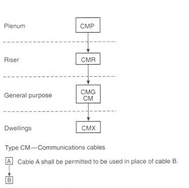
805.170 Protectors.
(A) Primary Protectors.
The primary protector shall be listed and consist of an arrester connected between each line conductor and ground in an appropriate mounting. Primary protector terminals shall be marked to indicate line and ground as applicable.
Informational Note: See ANSI/UL 497-2017, Standard for Protectors for Paired Conductor Communications Circuits, to determine applicable requirements for a listed primary protector.
(B) Secondary Protectors.
The secondary protector shall be listed as suitable to provide means to safely limit currents to less than the current-carrying capacity of listed indoor communications wire and cable, listed telephone set line cords, and listed communications terminal equipment having ports for external wire line communications circuits. Any overvoltage protection, arresters, or grounding connection shall be connected on the equipment terminals side of the secondary protector current-limiting means.
Informational Note: See ANSI/UL 497A-2019, Standard for Secondary Protectors for Communications Circuits, to determine applicable requirements for a listed secondary protector.
805.173 Drop Wire and Cable.
Communications wires and cables without a metallic shield, running from the last outdoor support to the primary protector, shall be listed as being suitable for the purpose and shall have current-carrying capacity as specified in 805.90(A)(1) (b) or (A)(1) (c).
Article 810
Antenna Systems
810.1 Scope.
This article covers antenna systems for radio and television receiving equipment, amateur and citizen band radio transmitting and receiving equipment, and certain features of transmitter safety. This article covers antennas such as wire-strung type, multi-element, vertical rod, flat, or parabolic and also covers the wiring and cabling that connect them to equipment. This article does not cover equipment and antennas used for coupling carrier current to power line conductors.
810.3 Other Articles.
Wiring from the source of power to and between devices connected to the interior wiring system shall comply with the following:
- Chapters 1 through 4 other than as modified by Parts I and II of Article 640.
- Coaxial cables that connect antennas to equipment shall comply with the appropriate article of Chapter 8.
- Wiring and equipment installed in hazardous (classified) locations shall comply with the appropriate requirements in Chapter 5.
810.4 Community Television Antenna.
The installation of the antenna shall comply with this article. The installation of the distribution system shall comply with the appropriate article of Chapter 8.
810.5 Radio Noise Suppression.
Radio interference eliminators, interference capacitors, or noise suppressors connected to power-supply leads shall be of a listed type. They shall not be exposed to physical damage.
810.6 Antenna Lead-in Protectors.
If an antenna lead-in surge protector is installed, it shall be listed as being suitable for limiting surges on the cable that connects the antenna to the receiver/transmitter electronics and shall be connected between the conductors and the grounded shield or other ground connection. The antenna lead-in protector shall be grounded using a bonding conductor or grounding electrode conductor installed in accordance with 810.21 (F).
Informational Note: See UL 497E, Outline of Investigation for Protectors for Antenna Lead-In Conductors, for information concerning protectors for antenna lead-in conductors.
810.7 Grounding Devices.
If bonding or grounding is required, devices used to connect a shield, a sheath, noncurrent-carrying metal members of a cable, or metal parts of equipment or antennas to a bonding conductor or grounding electrode conductor shall be listed or be part of listed equipment.
810.11 Material.
Antennas and lead-in conductors shall be of hard-drawn copper, bronze, aluminum alloy, copper-clad steel, or other high-strength, corrosion-resistant material.
Exception: Soft-drawn or medium-drawn copper shall be permitted for lead-in conductors if the maximum span between points of support is less than 11 m (35 ft).
810.12 Supports.
Outdoor antennas and lead-in conductors shall be securely supported. The antennas or lead-in conductors shall not be attached to the electric service mast. They shall not be attached to poles or similar structures carrying open electric light or power wires or trolley wires of over 250 volts between conductors. Insulators supporting the antenna conductors shall have sufficient mechanical strength to safely support the conductors. Lead-in conductors shall be securely attached to the antennas.
810.13 Avoidance of Contacts With Conductors of Other Systems.
Outdoor antennas and lead-in conductors from an antenna to a building shall not cross over open conductors of electric light or power circuits and shall be kept well away from all such circuits so as to avoid the possibility of accidental contact. Where proximity to open electric light or power service conductors of less than 250 volts between conductors cannot be avoided, the installation shall be such as to provide a clearance of at least 600 mm (2 ft).
Where practicable, antenna conductors shall be installed so as not to cross under open electric light or power conductors.
810.15 Grounding or Bonding.
Masts and metal structures supporting antennas shall be grounded or bonded in accordance with 810.21, unless the antenna and its related supporting mast or structure are within a zone of protection defined by a 46 m (150 ft) radius rolling sphere.
Informational Note: See NFPA 780-2020, Standard for the Installation of Lightning Protection Systems, 4.7.3.1, for the application of the term rolling sphere.
810.16 Size of Wire-Strung Antenna — Receiving Station.
(A) Size of Antenna Conductors.
Outdoor antenna conductors for receiving stations shall be of a size not less than given in Table 810.16(A).
Table 810.16 (A) Size of Receiving Station Outdoor Antenna Conductors.
| Material | Minimum Size of Conductors (AWG) Where Maximum Open Span Length Is | ||
|---|---|---|---|
| Less Than 11 m (35 ft) | 11 m to 45 m (35 ft to 150 ft) | Over 45 m (150 ft) | |
| Aluminum alloy, hard-drawn copper | 19 | 14 | 12 |
| Copper-clad steel, bronze, or other high-strength material | 20 | 17 | 14 |
(B) Self-Supporting Antennas.
Outdoor antennas, such as vertical rods and flat, parabolic, or dipole structures, shall be of corrosion-resistant materials and of strength suitable to withstand ice and wind loading conditions and shall be located well away from overhead conductors of electric light and power circuits of over 150 volts to ground, so as to avoid the possibility of the antenna or structure falling into or making accidental contact with such circuits.
810.17 Size of Lead-in — Receiving Station.
Lead-in conductors from outside antennas for receiving stations shall, for various maximum open span lengths, be of such size as to have a tensile strength at least as great as that of the conductors for antennas as specified in 810.16. If the lead-in consists of two or more conductors that are twisted together, are enclosed in the same covering, or are concentric, the conductor size shall, for various maximum open span lengths, be such that the tensile strength of the combination is at least as great as that of the conductors for antennas as specified in 810.16.
810.18 Clearances — Receiving Stations.
(A) Outside of Buildings.
Lead-in conductors attached to buildings shall be installed so that they cannot swing closer than 600 mm (2 ft) to the conductors of circuits of 250 volts or less between conductors, or 3.0 m (10 ft) to the conductors of circuits of over 250 volts between conductors, except that in the case of circuits not over 150 volts between conductors, if all conductors involved are supported so as to ensure permanent separation, the clearance shall be permitted to be reduced but shall not be less than 100 mm (4 in.). The clearance between lead-in conductors and any conductor forming a part of a lightning protection system shall not be less than 1.8 m (6 ft). Underground conductors shall be separated at least 300 mm (12 in.) from conductors of any light or power circuits or Class 1 circuits.
Exception: The separation and clearance requirements shall not apply if the electric light or power conductors, Class 1 conductors, or lead-in conductors are installed in raceways or metal cable armor.
Informational Note No. 1: See 250.60 for grounding associated with lightning protection components - strike termination devices. See NFPA 780-2020, Standard for the Installation of Lightning Protection Systems, for detailed information on grounding, bonding, and spacing from lightning protection systems, and the calculation of specific separation distances using the sideflash equation in Section 4.6.
Informational Note No. 2: See NFPA 780-2020, Standard for the Installation of Lighting Protection Systems, for information on bonding or separation of metal raceways, enclosures, frames, and other non-current-carrying metal parts of electrical equipment installed on a building equipped with a lightning protection system. Separation from lightning protection conductors is typically 1.8 m (6 ft) through air or 900 mm (3 ft) through dense materials such as concrete, brick, or wood.
(B) Antennas and Lead-Ins — Indoors.
Indoor antennas and indoor lead-ins shall not be run nearer than 50 mm (2 in.) to conductors of other wiring systems in the premises unless one of the following conditions applies:
(C) In Boxes or Other Enclosures.
Indoor antennas and indoor lead-ins shall be permitted to occupy the same box or enclosure with conductors of other wiring systems if separated from such other conductors by an effective permanently installed barrier.
810.19 Electrical Supply Circuits Used in Lieu of Antenna — Receiving Stations.
If an electrical supply circuit is used in lieu of an antenna, the device by which the radio receiving set is connected to the supply circuit shall be listed.
810.20 Antenna Discharge Units — Receiving Stations.
(A) General Requirement.
Each lead-in conductor from an outdoor antenna shall be provided with a listed antenna discharge unit.
Exception: A separate antenna discharge unit is not required if the lead-in conductors are enclosed in a continuous metal shield that complies with one of the following:
(2) Is protected by an antenna discharge unit
(B) Location.
Antenna discharge units shall be located outside the building or inside the building between the point of entrance of the lead-in and the radio set or transformers and as near as practicable to the entrance of the conductors to the building. The antenna discharge unit shall not be located near combustible material or in a hazardous (classified) location as defined in accordance with 500.5 and 505.5.
810.21 Bonding Conductors and Grounding Electrode Conductors — Receiving Stations.
Bonding conductors and grounding electrode conductors shall comply with 810.21(A) through 810.21 (K).
(A) Material.
The bonding conductor or grounding electrode conductor shall be of copper, aluminum, copper-clad steel, copper-clad aluminum, bronze, or similar corrosion-resistant material. Aluminum or copper-clad aluminum bonding conductors or grounding electrode conductors shall not be used if subject to corrosive conditions or in direct contact with masonry or the earth or where subject to corrosive conditions. If used outside, aluminum or copper-clad aluminum conductors shall not be installed within 450 mm (18 in.) of the earth.
(C) Supports.
The bonding conductor or grounding electrode conductor shall be securely fastened in place and shall be permitted to be directly attached to the surface wired over without the use of insulating supports.
Exception: Where proper support cannot be provided, the size of the bonding conductors or grounding electrode conductors shall be increased proportionately.
(D) Physical Protection.
Bonding conductors and grounding electrode conductors shall be protected where exposed to physical damage. Where the bonding conductor or grounding electrode conductor is installed in a metal raceway, both ends of the raceway shall be bonded to the contained conductor or to the same terminal or electrode to which the bonding conductor or grounding electrode conductor is connected.
(E) Run in Straight Line.
The bonding conductor or grounding electrode conductor for an antenna mast or antenna discharge unit shall be run in as straight a line as practicable.
(F) Electrode.
The bonding conductor or grounding electrode conductor shall be connected as required in 810.21(F)(1) through 810.21(F)(3).
(1) In Buildings or Structures With an Intersystem Bonding Termination.
If the building or structure served has an inter-system bonding termination as required by 250.94, the bonding conductor shall be connected to the intersystem bonding termination.
(2) In Buildings or Structures With Grounding Means.
If the building or structure served has no intersystem bonding termination, the bonding conductor or grounding electrode conductor shall be connected to the nearest accessible location on one of the following:
- The building or structure grounding electrode system as covered in 250.50
- The power service accessible means external to the building, as covered in 250.94
- The nonflexible metal power service raceway
- The service equipment enclosure
- The grounding electrode conductor or the grounding electrode conductor metal enclosures of the power service
- The grounded interior metal water piping systems, within 1.52 m (5 ft) from its point of entrance to the building, as covered in 250.52
A bonding device intended to provide a termination point for the bonding conductor (intersystem bonding) shall not interfere with the opening of an equipment enclosure. A bonding device shall be mounted on nonremovable parts. A bonding device shall not be mounted on a door or cover even if the door or cover is nonremovable.
(3) In Buildings or Structures Without an Intersystem Bonding Termination or Grounding Means.
If the building or structure served has no intersystem bonding termination or grounding means as described in 810.21(F)(2), the grounding electrode conductor shall be connected to a grounding electrode as described in 250.52.
(G) Inside or Outside Building.
The bonding conductor or grounding electrode conductor shall be permitted to be run either inside or outside the building.
(H) Size.
The bonding conductor or grounding electrode conductor shall not be smaller than 10 AWG copper, 8 AWG aluminum, or 17 AWG copper-clad steel or bronze.
(I) Common Ground.
A single bonding conductor or grounding electrode conductor shall be permitted for both protective and operating purposes.
(J) Bonding of Electrodes.
A bonding jumper not smaller than 6 AWG copper or equivalent shall be connected between the radio and television equipment grounding electrode and the power grounding electrode system at the building or structure served if separate electrodes are used.
810.52 Size of Conductors.
Antenna conductors for transmitting and receiving stations shall be of a size not less than given in Table 810.52.
Table 810.52 Size of Outdoor Antenna Conductors.
| Material | Minimum Size of Conductors (AWG) If Maximum Open Span Length Is | |
|---|---|---|
| Less Than 45 m (150 ft) | Over 45 m (150 ft) | |
| Hard-drawn copper | 14 | 10 |
| Copper-clad steel, bronze, or other high-strength material | 14 | 12 |
810.53 Size of Lead-in Conductors.
Lead-in conductors for transmitting stations shall, for various maximum span lengths, be of a size at least as great as that of conductors for antennas as specified in 810.52.
810.54 Clearance on Building.
Antenna conductors for transmitting stations, attached to buildings, shall be firmly mounted at least 75 mm (3 in.) clear of the surface of the building on nonabsorbent insulating supports, such as treated pins or brackets equipped with insulators having not less than 75-mm (3-in.) creepage and airgap distances. Lead-in conductors attached to buildings shall also comply with these requirements.
810.55 Entrance to Building.
Except where protected with a continuous metallic shield that is grounded with a conductor in accordance with 810.58, lead-in conductors for transmitting stations shall enter buildings by one of the following methods:
- Through a rigid, noncombustible, nonabsorbent insulating tube or bushing
- Through an opening provided for the purpose in which the entrance conductors are firmly secured so as to provide a clearance of at least 50 mm (2 in.)
- Through a drilled window pane
810.56 Protection Against Accidental Contact.
Lead-in conductors to radio transmitters shall be located or installed so as to make accidental contact with them difficult.
810.57 Antenna Discharge Units — Transmitting Stations.
Each lead-in conductor for outdoor antennas shall be provided with an antenna discharge unit or other suitable means that drain static charges from the antenna system.
Exception No. 1: If the lead-in conductor is protected by a continuous metal shield that is grounded with a conductor in accordance with 810.58, an antenna discharge unit or other suitable means shall not be required for the lead-in conductor.
810.58 Bonding Conductors and Grounding Electrode Conductors — Amateur and Citizen Band Transmitting and Receiving Stations.
Bonding conductors and grounding electrode conductors shall comply with 810.58(A) through 810.58(C).
(A) Other Sections.
All bonding conductors and grounding electrode conductors for amateur and citizen band transmitting and receiving stations shall comply with 810.21(A) through 810.21(C).
(B) Size of Protective Bonding Conductor or Grounding Electrode Conductor.
The protective bonding conductor or grounding electrode conductor for transmitting stations shall be as large as the lead-in but not smaller than 10 AWG copper, bronze, or copper-clad steel.
(C) Size of Operating Bonding Conductor or Grounding Electrode Conductor.
The operating bonding conductor or grounding electrode conductor for transmitting stations shall not be less than 14 AWG copper or its equivalent.
810.70 Separation From Other Conductors.
All conductors inside the building shall be separated at least 100 mm (4 in.) from the conductors of any electric light, power, or signaling circuit unless one of the following conditions applies:
- The conductors of a permanent audio system are installed in compliance with Parts I and II of Article 640.
- The conductors of portable and temporary audio systems are installed in compliance with Parts I and III of Article 640.
- The conductors are separated from such other conductors by a continuous and firmly fixed nonconductor.
810.71 General.
(A) Enclosing.
The transmitter shall be enclosed in a metal frame or grille or separated from the operating space by a barrier or other equivalent means, all metallic parts of which are effectively connected to a bonding conductor or grounding electrode conductor.
(B) Grounding of Controls.
All external metal handles and controls accessible to the operating personnel shall be effectively connected to an equipment grounding conductor if the transmitter is powered by the premises wiring system or grounded with a conductor in accordance with 810.21.
(C) Interlocks on Doors.
All access doors shall be provided with interlocks that disconnect all voltages of over 350 volts between conductors when any access door is opened.
Article 820
Community Antenna Television and Radio Distribution Systems
820.1 Scope.
This article covers coaxial cable distribution of radio frequency signals typically employed in community antenna television (CATV) systems.
820.3 Other Articles.
The wiring methods of Article 830 shall be permitted to substitute for the wiring methods of Article 820.
Informational Note: Use of Article 830 wiring methods will facilitate the upgrading of Article 820 installations to network-powered broadband applications.
820.15 Power Limitations.
Coaxial cable shall be permitted to deliver power to equipment that is directly associated with the radio frequency distribution system if the voltage is not over 60 volts and if the current is supplied by a transformer or other device that has power-limiting characteristics.
820.93 Grounding of the Outer Conductive Shield of Coaxial Cables.
Coaxial cables entering buildings or attached to buildings shall comply with 820.93(A) or (B). Where the outer conductive shield of a coaxial cable is grounded, no other protective devices shall be required. For purposes of this section, grounding located at mobile home service equipment located within 9.0 m (30 ft) of the exterior wall of the mobile home it serves, or at a mobile home disconnecting means grounded in accordance with 250.32 and located within 9.0 m (30 ft) of the exterior wall of the mobile home it serves, shall be considered to meet the requirements of this section.
Informational Note: Selecting a grounding block location to achieve the shortest practicable bonding conductor or grounding electrode conductor helps limit potential differences between CATV and other metallic systems.
(A) Entering Buildings.
In installations where the coaxial cable enters the building, the outer conductive shield shall be grounded in accordance with 820.100. The grounding shall be as close as practicable to the point of entrance.
(C) Location.
Where installed, a listed primary protector shall be applied on each community antenna and radio distribution (CATV) cable external to the premises. The listed primary protector shall be located as close as practicable to the entrance point of the cable on either side or integral to the ground block.
(D) Hazardous (Classified) Locations.
820.100 Cable Bonding and Grounding.
The shield of the coaxial cable shall be bonded or grounded as specified in 820.100(A) and (B).
Exception: For communications systems using coaxial cable completely contained within the building (i.e., they do not exit the building) or the exterior zone of protection defined by a 46 m (150 ft) radius rolling sphere and isolated from outside cable plant, the shield shall be permitted to be grounded by a connection to an equipment grounding conductor as described in 250.118. Connecting to an equipment grounding conductor through a grounded receptacle using a dedicated bonding jumper and a permanently connected listed device shall be permitted. Use of a cord and plug for the connection to an equipment grounding conductor shall not be permitted.
Informational Note: See NFPA 780-2020, Standard for the Installation of Lightning Protection Systems, 4.7.3.1, for the application of the term rolling sphere.
820.154 Substitutions of Listed CATV Cables.
The substitutions for coaxial cables in Table 820.154 and illustrated in Figure 820.154 shall be permitted.
Informational Note: The substitute cables in Table 820.154 and Figure 820.154 are only coaxial-type cables.
Table 820.154 Coaxial Cable Uses and Permitted Substitutions.
| Cable Type | Permitted Substitutions |
|---|---|
| CATVP | CMP, BLP |
| CATVR | CATVP, CMP, CMR, BMR, BLP, BLR |
| CATV | CATVP, CMP, CATVR. CMR, CMG, CM, BMR, BM, BLP, BLR, BL |
| CATVX | CATVP, CMP, CATVR, CMR, CATV, CMG, CM, BMR, BM, BLP, BLR, BL, BLX |
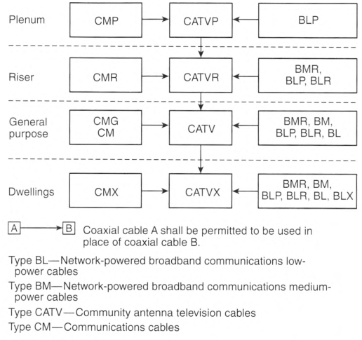
Article 830
Network-Powered Broadband Communications Systems
830.1 Scope.
This article covers network-powered broadband communications systems that provide any combination of voice, audio, video, data, and interactive services through a network interface unit.
Informational Note: A typical basic system configuration includes a cable supplying power and broadband signal to a network interface unit that converts the broadband signal to the component signals. Typical cables are coaxial cable with both broadband signal and power on the center conductor, composite metallic cable with a coaxial member(s) or twisted pair members for the broadband signal and twisted pair members for power, and hybrid optical fiber cable with a pair of conductors for power. Larger systems may also include network components such as amplifiers that require network power.
830.15 Power Limitations.
Network-powered broadband communications systems shall be classified as having low- or medium-power sources as specified in the following:
- Sources shall be classified as defined in Table 830.15.
- Direct-current power sources exceeding 150 volts to ground, but no more than 200 volts to ground, with the current to ground limited to 10 mA dc, that meet the current and power limitation for medium-power sources in Table 830.15 shall be classified as medium-power sources.
Informational Note: See UL 60950-21-2007, Standard for Safety for Information Technology Equipment - Safety - Part 21: Remote Power Feeding, for listing information on equipment that complies with 830.15(2).
Table 830.15 Limitations for Network-Powered Broadband Communications Systems.
| Network Power Source | Low | Medium |
|---|---|---|
| Circuit voltage, Vmax (volts)1 | 0—100 | 0—150 |
| Power limitation, VAmax (volt-amperes)1 | 250 | 250 |
| Current limitation, Imax (amperes)1 | 1000/Vmax | 1000/Vmax |
| Maximum power rating (volt-amperes) | 100 | 100 |
| Maximum voltage rating (volts) | 100 | 150 |
| Maximum overcurrent protection (amperes)2 | 100/Vmax | NA |
1 Vmax, Imax, and VAmax are determined with the current-limiting impedance in the circuit (not bypassed) as follows:
Vmax - Maximum system voltage regardless of load with rated input applied
Imax - Maximum system current under any noncapacitive load, including short circuit, and with overcurrent protection bypassed if used. Imax limits apply after 1 minute of operation
VAmax - Maximum volt-ampere output after 1 minute of operation regardless of load and overcurrent protection bypassed if used
2Overcurrent protection is not required if the current limiting device provides equivalent current limitation and the current-limiting device does not reset until power or the load is removed.
830.40 Entrance Cables.
Network-powered broadband communications cables located outside and entering buildings shall comply with 830.40(A) and (B).
(A) Medium-Power Circuits.
Medium-power network-powered broadband communications circuits located outside and entering buildings shall be installed using Type BMU, Type BM, or Type BMR network-powered broadband communications medium-power cables.
(B) Low-Power Circuits.
Low-power network-powered broadband communications circuits located outside and entering buildings shall be installed using Type BLU or Type BLX low-power network-powered broadband communications cables. Cables shown in Table 830.154 shall be permitted to substitute.
830.44 Overhead (Aerial) Cables.
Overhead (aerial) network powered broadband communications cables shall comply with 830.44(A) through (F).
(B) Clearance From Ground.
Overhead (aerial) spans of network-powered broadband communications cables shall conform to not less than the following:
- 2.9 m (91/2 ft) - above finished grade, sidewalks, or from any platform or projection from which they might be reached and accessible to pedestrians only
- 3.5 m (111/2 ft) - over residential property and driveways, and those commercial areas not subject to truck traffic
- 4.7 m (151/2 ft) - over public streets, alleys, roads, parking areas subject to truck traffic, driveways on other than residential property, and other land traversed by vehicles such as cultivated, grazing, forest, and orchard
(D) Final Spans.
Final spans of network-powered broadband communications cables without an outer jacket shall be permitted to be attached to the building, but they shall be kept not less than 900 mm (3 ft) from windows that are designed to be opened, doors, porches, balconies, ladders, stairs, fire escapes, or similar locations.
Exception: Conductors run above the top level of a window shall be permitted to be less than the 900-mm (3-ft) requirement above.
Overhead (aerial) network-powered broadband communications cables shall not be installed beneath openings through which materials might be moved, such as openings in farm and commercial buildings, and shall not be installed where they obstruct entrance to these building openings.
(E) Between Buildings.
Network-powered broadband communications cables extending between buildings or structures, and also the supports or attachment fixtures, shall be identified as suitable for outdoor aerial applications and shall have sufficient strength to withstand the loads to which they may be subjected.
Exception: Where a network-powered broadband communications cable does not have sufficient strength to be self-supporting, it shall be attached to a supporting messenger cable that, together with the attachment fixtures or supports, shall be acceptable for the purpose and shall have sufficient strength to withstand the loads to which they may be subjected.
(F) On Buildings.
Where attached to buildings, network-powered broadband communications cables shall be securely fastened in such a manner that they are separated from other conductors in accordance with 830.44(F)(1) through (F)(3).
(1) Electric Light or Power.
The network-powered broadband communications cable shall have a separation of at least 100 mm (4 in.) from electric light, power, Class 1, or non-power-limited fire alarm circuit conductors not in raceway or cable, or be permanently separated from conductors of the other system by a continuous and firmly fixed nonconductor in addition to the insulation on the wires.
(2) Other Communications Systems.
Network-powered broadband communications cables shall be installed so that there will be no unnecessary interference in the maintenance of the separate systems. In no case shall the conductors, cables, messenger strand, or equipment of one system cause abrasion to the conductors, cables, messenger strand, or equipment of any other system.
(3) Protection From Damage.
Network-powered broadband communications cables attached to buildings or structures and located within 2.5 m (8 ft) of finished grade shall be protected by enclosures, raceways, or other approved means.
Exception: A low-power network-powered broadband communications circuit that is equipped with a listed fault protection device, appropriate to the network-powered broadband communications cable used, and located on the network side of the network-powered broadband communications cable shall not be required to be additionally protected by enclosures, raceways, or other approved means.
830.47 Underground Network-Powered Broadband Communications Cables Entering Buildings.
Underground network-powered broadband communications cables entering buildings shall comply with 830.47(A) and (B).
(A) Protection From Physical Damage.
Direct-buried cable, conduit, or other raceways shall be installed to meet the minimum cover requirements of Table 830.47(A). In addition, direct-buried cables emerging from the ground shall be protected by enclosures, raceways, or other approved means extending from the minimum cover distance required by Table 830.47(A) below grade to a point at least 2.5 m (8 ft) above finished grade. In no case shall the protection be required to exceed 450 mm (18 in.) below finished grade. Types BMU and BLU direct-buried cables emerging from the ground shall be installed in rigid metal conduit (RMC), intermediate metal conduit (IMC), rigid nonmetallic conduit, or other approved means extending from the minimum cover distance required by Table 830.47(A) below grade to the point of entrance.
Exception: Protection from physical damage shall not be required if a low-power network-powered broadband communications circuit is equipped with a listed fault protection device that is located on the network side of the network-powered broadband cable being protected and the device is appropriate to the network-powered broadband communications cable used.
Table 830.47(A) Network-Powered Broadband Communications Systems Minimum Cover Requirements.
| Location of Wiring Method or Circuit | Direct Burial Cables | Rigid Metal Conduit (RMC) or Intermediate Metal Conduit (IMC) | Nonmetallic Raceways Listed for Direct Burial; Without Concrete Encasement or Other Approved Raceways | |||
|---|---|---|---|---|---|---|
| mm | in. | mm | in. | mm | in. | |
| All locations not specified below | 450 | 18 | 150 | 6 | 300 | 12 |
| In trench below 50 mm (2 in.) thick concrete or equivalent | 300 | 12 | 150 | 6 | 150 | 6 |
| Under a building (in raceway only) | 0 | 0 | 0 | 0 | 0 | 0 |
| Under minimum of 100 mm (4 in.) thick concrete exterior slab with no vehicular traffic and the slab extending not less than 150 mm (6 in.) beyond the underground installation | 300 | 12 | 100 | 4 | 100 | 4 |
| One- and two-family dwelling driveways and outdoor parking areas and used only for dwelling-related purposes | 300 | 12 | 300 | 12 | 300 | 12 |
Notes:
- Cover is the shortest distance measured between a point on the top surface of any direct-buried cable, conduit, or other raceway and the top surface of finished grade, concrete, or similar cover.
- Raceways approved for burial only where concrete encased shall require a concrete envelope not less than 50 mm (2 in.) thick.
- Lesser depths shall be permitted where cables rise for terminations or splices or where access is otherwise required.
- Where solid rock is encountered, all wiring shall be installed in metal or nonmetallic raceway permitted for direct burial.
The raceways shall be covered by a minimum of 50 mm (2 in.) of concrete extending down to rock.
830.90 Primary Electrical Protection.
(A) Application.
Primary electrical protection shall be provided on all network-powered broadband communications conductors that are neither grounded nor interrupted and are run partly or entirely in aerial cable not confined within a block. Also, primary electrical protection shall be provided on all aerial or underground network-powered broadband communications conductors that are neither grounded nor interrupted and are located within the block containing the building served so as to be exposed to lightning or accidental contact with electric light or power conductors operating at over 300 volts to ground.
Exception: Primary electrical protection shall not be required on the network-powered broadband communications conductors where electrical protection is provided on the derived circuit(s) (output side of the NIU) in accordance with 830.90(B)(3).
Informational Note No. 1: On network-powered broadband communications conductors not exposed to lightning or accidental contact with power conductors, providing primary electrical protection in accordance with this article helps protect against other hazards, such as ground potential rise caused by power fault currents, and above-normal voltages induced by fault currents on power circuits in proximity to the network-powered broadband communications conductors.
Informational Note No. 2: Network-powered broadband communications circuits are considered to have a lightning exposure unless one or more of the following conditions exist:
- Circuits in large metropolitan areas where buildings are close together and sufficiently high to intercept lightning.
- Areas having an average of five or fewer thunderstorm days each year and earth resistivity of less than 100 ohmmeters. Such areas are found along the Pacific coast.
Informational Note No. 3: See NFPA 780-2020, Standard for the Installation of Lightning Protection Systems, for information on lightning protection systems.
(1) Fuseless Primary Protectors.
Fuseless-type primary protectors shall be permitted where power fault currents on all protected conductors in the cable are safely limited to a value no greater than the current-carrying capacity of the primary protector and of the primary protector bonding conductor or grounding electrode conductor.
(2) Fused Primary Protectors.
Where the requirements listed in 830.90(A)(1) are not met, fused-type primary protectors shall be used. Fused-type primary protectors shall consist of an arrester connected between each conductor to be protected and ground, a fuse in series with each conductor to be protected, and an appropriate mounting arrangement. Fused primary protector terminals shall be marked to indicate line, instrument, and ground, as applicable.
(B) Location.
The location of the primary protector, where required, shall comply with the following:
- A listed primary protector shall be applied on each network-powered broadband communications cable external to and on the network side of the network interface unit.
- The primary protector function shall be an integral part of and contained in the network interface unit. The network interface unit shall be listed as being suitable for application with network-powered broadband communications systems and shall have an external marking indicating that it contains primary electrical protection.
- The primary protector(s) shall be provided on the derived circuit(s) (output side of the NIU), and the combination of the NIU and the protector(s) shall be listed as being suitable for application with network-powered broadband communications systems.
A primary protector, whether provided integrally or external to the network interface unit, shall be located as close as practicable to the point of entrance.
For purposes of this section, a network interface unit and any externally provided primary protectors located at mobile home service equipment located in sight from and not more than 9.0 m (30 ft) from the exterior wall of the mobile home it serves, or at a mobile home disconnecting means grounded in accordance with 250.32 and located in sight from and not more than 9.0 m (30 ft) from the exterior wall of the mobile home it serves, shall be considered to meet the requirements of this section.
Informational Note: Selecting a network interface unit and primary protector location to achieve the shortest practicable primary protector bonding conductor or grounding electrode conductor helps limit potential differences between communications circuits and other metallic systems.
830.93 Grounding or Interruption of Metallic Members of Network-Powered Broadband Communications Cables.
Network-powered communications cables entering buildings or attaching to buildings shall comply with 830.93(A) or (B).
For purposes of this section, grounding located at mobile home service equipment located within 9.0 m (30 ft) of the exterior wall of the mobile home it serves, or at a mobile home disconnecting means grounded in accordance with 250.32 and located within 9.0 m (30 ft) of the exterior wall of the mobile home it serves, shall be considered to meet the requirements of this section.
Informational Note: Selecting a grounding location to achieve the shortest practicable bonding conductor or grounding electrode conductor helps limit potential differences between the network-powered broadband communications circuits and other metallic systems.
(A) Entering Buildings.
In installations where the network-powered communications cable enters the building, the shield shall be grounded in accordance with 800.100, and metallic members of the cable not used for communications or powering shall be grounded in accordance with 800.100 or interrupted by an insulating joint or equivalent device. The grounding or interruption shall be as close as practicable to the point of entrance.
(B) Terminating Outside of the Building.
In installations where the network-powered communications cable is terminated outside of the building, the shield shall be grounded in accordance with 800.100, and metallic members of the cable not used for communications or powering shall be grounded in accordance with 800.100 or interrupted by an insulating joint or equivalent device. The grounding or interruption shall be as close as practicable to the point of attachment of the NIU.
830.133 Installation of Network-Powered Broadband Communications Cables and Equipment.
Cable and equipment installations within buildings shall comply with 830.133(A) through (C), as applicable.
(A) Separation of Conductors.
(1) In Raceways. Cable Trays, Boxes, Enclosures, and Cable Routing Assemblies.
- Low- and Medium-Power Network-Powered Broadband Communications Circuit Cables. Low- and medium-power network-powered broadband communications cables shall be permitted in the same raceway, cable tray, box, enclosure, or cable routing assembly.
-
Low-Power Network-Powered Broadband Communications Circuit Cables with Other Circuits. Low-power network-powered broadband communications cables shall be permitted in the same raceway, cable tray, box, enclosure, or cable routing assembly with jacketed cables of any of the following circuits:
- Class 2 and Class 3 remote-control, signaling, and power-limited circuits in compliance with Parts I and II of Article 725
- Power-limited fire alarm systems in compliance with Parts I and III of Article 760
- Communications circuits in compliance with Parts I and IV of Article 805
- Nonconductive and conductive optical fiber cables in compliance with Parts I and V of Article 770
- Community antenna television and radio distribution systems in compliance with Parts I and V of Article 820
-
Medium-Power Network-Powered Broadband Communications Circuit Cables with Optical Fiber Cables and Other Communications Cables. Medium-power network-powered broadband communications cables shall not be permitted in the same raceway, cable tray, box, enclosure, or cable routing assembly with conductors of any of the following circuits:
- Communications circuits in compliance with Parts I and IV of Article 805
- Conductive optical fiber cables in compliance with Parts I and V of Article 770
- Community antenna television and radio distribution systems in compliance with Parts I and V of Article 820
-
Medium-Power Network-Powered Broadband Communications Circuit Cables with Other Circuits. Medium-power network-powered broadband communications cables shall not be permitted in the same raceway, cable tray, box, enclosure, or cable routing assembly with conductors of any of the following circuits:
- Class 2 and Class 3 remote-control, signaling, and power-limited circuits in compliance with Parts I and II of Article 725
- Power-limited fire alarm systems in compliance with Parts I and III of Article 760
- Electric Light, Power, Class 1, Nonpowered Broadband Communications Circuit Cables. Network-powered broadband communications cable shall not be placed in any raceway, cable tray, compartment, outlet box, junction box, or similar fittings with conductors of electric light, power, Class 1, or non-power-limited fire alarm circuit cables.
Exception No. 1: Network-powered broadband communications cable shall be permitted to be placed in a raceway, cable tray, compartment, outlet box, junction box, or similar fittings with conductors of electric light, power, Class 1, or non-power-limited fire alarm circuit cables where all of the conductors of electric light, power, Class 1, non-power-limited fire alarm circuits are separated from all of the network-powered broadband communications cables by a permanent barrier or listed divider.
Exception No. 2: Where power circuit conductors in outlet boxes, junction boxes, or similar fittings or compartments where such conductors are introduced solely for power supply to the network-powered broadband communications system distribution equipment, the power circuit conductors shall be routed within the enclosure to maintain a minimum 6 mm (1/4 in.) separation from network-powered broadband communications cables.
(2) Other Applications.
Network-powered broadband communications cable shall be separated at least 50 mm (2 in.) from conductors of any electric light, power, Class 1, and non-power-limited fire alarm circuits.
Exception No. 1: Separation shall not be. required where: (1) all of the conductors of electric light, power, Class 1, and non-power-limited fire alarm circuits are in a raceway or in metal-sheathed, metal-clad, nonmetallic-sheathed, Type AC, or Type UF cables, or (2) all of the network-powered broadband communications cables are encased in a raceway.
Exception No. 2: Separation shall not be required where the network-powered broadband communications cables are permanently separated from the conductors of electric light, power, Class 1, and non-power-limited fire alarm circuits by a continuous and firmly fixed nonconductor, such as porcelain tubes or flexible tubing, in addition to the insulation on the wire.
830.154 Substitutions of Network-Powered Broadband Communications System Cables.
The substitutions for network-powered broadband system cables listed in Table 830.154 shall be permitted.
Table 830.154 Cable Substitutions.
| Cable Type | Permitted Cable Substitutions |
|---|---|
| BM | BMR |
| BLP | CMP, CL3P |
| BLR | CMP, CL3P, CMR, CL3R, BLP, BMR |
| BL | CMP, CMR, CM, CMG, CL3P, CL3R, CL3, BMR, BM, BLP, BLR |
| BLX | CMP, CMR, CM, CMG, CMX, CL3P, CL3R, CL3, CL3X, BMR, BM, BLP, BRP, BL |
830.160 Bends.
830.179 Network-Powered Broadband Communications Equipment and Cables.
Network-powered broadband communications equipment and cables shall be listed and marked in accordance with 830.179(A) through (C).
Exception No. 1: This listing requirement shall not apply to community antenna television and radio distribution system coaxial cables that were installed prior to January 1, 2000, in accordance with Article 820 and are used for low-power network-powered broadband communications circuits.
Exception No. 2: Substitute cables for network-powered broadband communications cables shall be permitted as shown in Table 830.154.
(B) Network-Powered Broadband Communications Medium-Power Cables.
Network-powered broadband communications medium-power cables shall be factory-assembled cables consisting of a jacketed coaxial cable, a jacketed combination of coaxial cable and multiple individual conductors, or a jacketed combination of an optical fiber cable and multiple individual conductors. The insulation for the individual conductors shall be rated for 300 volts minimum. Cables intended for outdoor use shall be listed as suitable for the application. Cables shall be marked in accordance with 310.8. Type BMU cables shall be jacketed and listed as being suitable for outdoor underground use.
(C) Network-Powered Broadband Communication Low-Power Cables.
Network-powered broadband communications low-power cables shall be factory-assembled cables consisting of a jacketed coaxial cable, a jacketed combination of coaxial cable and multiple individual conductors, or a jacketed combination of an optical fiber cable and multiple individual conductors. The insulation for the individual conductors shall be rated for 300 volts minimum. Cables intended for outdoor use shall be listed as suitable for the application. Cables shall be marked in accordance with 310.8. Type BLU cables shall be jacketed and listed as being suitable for outdoor underground use.
Informational Note: See NFPA 780-2020, Standard for the Installation of Lightning Protection Systems, for the theory of the term rolling sphere.
Article 840
Premises-Powered Broadband Communications Systems
840.1 Scope.
This article covers premises-powered broadband communications systems.
Informational Note: A typical basic system configuration consists of an optical fiber, twisted pair, or coaxial cable to the premises supplying a broadband signal to a network terminal that converts the broadband signal into component signals, such as traditional telephone, video, high-speed Internet, and interactive services. Powering for the network terminal and network devices is typically accomplished through a premises power supply that might be built into the network terminal or provided as a separate unit. In order to provide communications in the event of a power interruption, a battery backup unit or an uninterruptible power supply (UPS) is typically part of the powering system.
840.47 Underground Wires and Cables Entering Buildings.
Direct-buried cables shall be installed to have a minimum cover of 150 mm (6 in.).
840.93 Grounding or Interruption.
Non-current-carrying metallic members of optical fiber cables, communications cables, or coaxial cables entering buildings or attaching to buildings shall comply with 840.93(A), (B), or (C), respectively.
(C) Coaxial Cables.
Where the network terminal is installed inside or outside of the building, with coaxial cables terminating at the network terminal, and is either entering, exiting, or attached to the outside of the building, 820.93 shall apply.
840.101 Premises Circuits Not Leaving the Building.
If the network terminal is served by a nonconductive optical fiber cable, or where any non-current-carrying metal member of a conductive optical fiber cable is interrupted by an insulating joint or equivalent device, and circuits that terminate at the network terminal are completely contained within the building (i.e., they do not exit the building), 840.101(A), (B), or (C) shall apply, as applicable.
(A) Coaxial Cable Shield Grounding.
The shield of coaxial cable shall be grounded by one of the following:
- Any of the methods described in 820.100 or 800.106
- A fixed connection to an equipment grounding conductor as described in 250.118
- Connection to the network terminal grounding terminal provided that the terminal is connected to ground by one of the methods described in 820.100 or 800.106, or to an equipment grounding conductor through a listed grounding device that wall retain the ground connection if the network terminal is unplugged
(B) Communications Circuit Grounding.
Communications circuits shall not be required to be grounded.
(C) Network Terminal Grounding.
The network terminal shall not be required to be grounded unless required by its listing. If the coaxial cable shield is separately grounded as described in 840.101 (A)(1) or 840.101 (A)(2), the use of a cord and plug for the connection to the network terminal grounding connection shall be permitted.
Informational Note: If required to be grounded, a listed device that extends the equipment grounding conductor from the receptacle to the network terminal equipment grounding terminal is permitted. Sizing of the extended equipment grounding conductor is covered in Table 250.122.
840.102 Premises Circuits Leaving the Building.
If circuits leave the building to power equipment remote to the building or outside the exterior zone of protection defined by a 46 m (150 ft) radius rolling sphere, the installation of communications wires and cables shall comply with 800.100 and 800.106, and the installation of coaxial cables shall comply with 820.100 and 800.106.
Informational Note: See NFPA 780-2020, Standard for the Installation of Lightning Protection Systems, for the application of the term rolling sphere.
840.160 Powering Circuits.
Listed communications cables, in addition to carrying the communications circuit, shall also be permitted to carry circuits for powering listed communications equipment. The power source shall be listed in accordance with 840.170(C). Installation of the listed 4-pair communications cables for a communications circuit or installation where 4-pair communications cables are substituted for Class 2 and Class 3 cables in accordance with 722.135(E) shall comply with 725.144.
Exception: Installing communications cables in compliance with 725.144 shall not be required for listed 4-pair communications cables where the rated current of the power source does not exceed 0.3 amperes in any conductor 24 AWG or larger.
Informational Note No. 1: A typical communications cable for this application is a 4-pair cable sometimes referred to as Category 5e (or higher) LAN cable or balanced twisted pair cable. These types of cables are often used to provide Ethernet-and Power over Ethernet (PoE)-type services.
Informational Note No. 2: See 725.144 for requirements to manage the temperature rise of bundles of cables that provide power.
840.170 Equipment and Cables.
Premises-powered broadband communications systems equipment and cables shall comply with 840.170(A) through (D).
(A) Network Terminal.
The network terminal and applicable grounding means shall be listed for application with premises-powered broadband communications systems.
Informational Note No. 1: See ANSI/UL 60950-1-2014, Standard for Safety of Information Technology Equipment, ANSI/ UL 498A-2015, Current Taps and Adapters; ANSI/UL 467-2013, Grounding and Bonding Equipment; or ANSI/UL 62368-1-2014, Audio/Video, Information and Communication Technology Equipment - Part I: Safety Requirements.
Informational Note No. 2: There are no requirements on the network terminal and its grounding methodologies except for those covered by the listing of the product.
(C) Power Source.
The power source for circuits intended to provide power over communications cables to remote equipment shall be limited in accordance with Table 11 (B) in Chapter 9 for voltage sources up to 60 volts dc and be listed as specified in either of the following:
- A power source shall be listed as specified in 725.60(A)(1), (A)(2), (A)(3), or (A)(4). The power sources shall not have the output connections paralleled or otherwise interconnected unless listed for such interconnection.
- A power source shall be listed as communications equipment for limited-power circuits.
Informational Note: See ANSI/UL 60950-1-2014, Standard far Safety of Information Technology Equipment-Safety — Part 1, or ANSI/UL 62368-1-2014, Audio/Video, Information and Communication Technology Equipment — Part 1: Safety Requirements. Typically, such circuits are used to interconnect equipment for the purpose of exchanging information (data).
(D) Accessory Equipment.
Communications accessory equipment and/or assemblies shall be listed for application with premises-powered communications systems.
Informational Note: See ANSI/UL 1863-2004, Communications-Circuit Accessories.