Article 300
General Requirements for Wiring Methods and Materials
300.1 Scope.
(A) All Wiring Installations.
This article covers general requirements for wiring methods and materials for all wiring installations unless modified by other articles in Chapter 3.
(B) Integral Parts of Equipment.
The requirements of this article are not intended to apply to the conductors that form an integral part of equipment, such as motors, controllers, motor control centers, or factory-assembled control equipment or listed utilization equipment.
(C) Metric Designators and Trade Sizes.
Metric designators and trade sizes for conduit, tubing, and associated fittings and accessories shall be in accordance with Table 300.1(C).
Table 300.1(C) Metric Designators and Trade Sizes.
| Metric Designator | Trade Size |
|---|---|
| 12 | 3/8 |
| 16 | 1/2 |
| 21 | 3/4 |
| 27 | 1 |
| 35 | l1/4 |
| 41 | 11/2 |
| 53 | 2 |
| 63 | 21/2 |
| 78 | 3 |
| 91 | 31/2 |
| 103 | 4 |
| 129 | 5 |
| 155 | 6 |
Note: The metric designators and trade sizes are for identification purposes only and are not actual dimensions.
300.3 Conductors.
(A) Single Conductors.
Single conductors specified in Table 310.4(1) shall only be permitted where installed as part of a recognized wiring method specified in Chapter 3.
Exception: Individual conductors shall be permitted where installed as separate overhead conductors in accordance with 225.6.
(B) Conductors of the Same Circuit.
All conductors of the same circuit and, where used, the grounded conductor and all equipment grounding conductors and bonding conductors shall be contained within the same raceway, conduit body, auxiliary gutter, cable tray, cablebus assembly, trench, cable, or cord unless otherwise permitted in accordance with 300.3(B)(1) through (B)(4).
(1) Paralleled Installations.
Conductors shall be permitted to be run in parallel in accordance with 310.10(G). The requirement to run all circuit conductors within the same raceway, auxiliary gutter, cable tray, trench, cable, or cord shall apply separately to each portion of the paralleled installation, and the equipment grounding conductors shall comply with 250.122. Connections, taps, or extensions made from paralleled conductors shall connect to all conductors of the paralleled set, grounded and ungrounded, as applicable. Parallel runs in cable trays shall comply with 392.20(C).
Exception: Conductors installed in nonmetallic raceways run underground shall be permitted to be arranged as isolated phase, neutral, and grounded conductor installations. The raceways shall be installed in close proximity, and the isolated phase, neutral, and grounded conductors shall comply with 300.20(B).
(2) Grounding and Bonding Conductors.
Equipment grounding conductors shall be permitted to be installed outside a raceway or cable assembly in accordance with 250.130(C) for certain existing installations or in accordance with 250.134, Exception No. 2, for dc circuits. Equipment bonding conductors shall be permitted to be installed on the outside of raceways in accordance with 250.102(E).
(3) Nonferrous Wiring Methods.
Conductors in wiring methods with a nonmetallic or other nonmagnetic sheath, where run in different raceways, auxiliary gutters, cable trays, trenches, cables, or cords, shall comply with 300.20(B). Conductors in single-conductor Type MI cable with a nonmagnetic sheath shall comply with 332.31. Conductors of single-conductor Type MC cable with a nonmagnetic sheath shall comply with 330.31, 330.116, and 300.20(B).
(4) Column-Width Panelboard Enclosures.
Where an auxiliary gutter runs between a column-width panelboard and a pull box, and the pull box includes neutral terminations, the neutral conductors of circuits supplied from the panelboard shall be permitted to originate in the pull box.
(C) Conductors of Different Systems.
(1) 1000 Volts AC, 1500 Volts DC, Nominal, or Less.
Conductors of ac and dc circuits rated 1000 volts ac, 1500 volts dc, nominal, or less shall be permitted to occupy the same equipment wiring enclosure, cable, or raceway. All conductors shall have an insulation rating equal to at least the maximum circuit voltage applied to any conductor within the enclosure, cable, or raceway.
Secondary wiring to electric-discharge lamps of 1000 volts ac, 1500 volts dc, or less, if insulated for the secondary voltage involved, shall be permitted to occupy the same luminaire, sign, or outline lighting enclosure as the branch-circuit conductors.
Informational Note No. 1: See 725.136(A) for Class 2 and Class 3 circuit conductors.
Informational Note No. 2: See 690.31(B) for photovoltaic source and output circuits.
300.4 Protection Against Physical Damage.
(A) Cables and Raceways Through Wood Members.
(1) Bored Holes.
In both exposed and concealed locations, where a cable- or raceway-type wiring method is installed through bored holes in joists, rafters, or wood members, holes shall be bored so that the edge of the hole is not less than 32 mm (11/4 in.) from the edges of the wood member. Where this distance cannot be maintained, the cable or raceway shall be protected from penetration by screws or nails by a steel plate(s) or bushing(s) at least 1.6 mm (1/16 in.) thick, and of appropriate length and width, installed to cover the area of the wiring.
Exception No. 1: Steel plates shall not be required to protect rigid metal conduit, intermediate metal conduit, rigid PVC conduit, RTRC, or electrical metallic tubing.
Exception No. 2: A listed and marked steel plate less than 1.6 mm (1/16 in.) thick that provides equal or better protection against nail or screw penetration shall be permitted.
(2) Notches in Wood.
Where there is no objection because of weakening the building structure, in both exposed and concealed locations, cables or raceways shall be permitted to be laid in notches in wood studs, joists, rafters, or other wood members where the cable or raceway at those points is protected from penetration by nails or screws by a steel plate at least 1.6 mm (1/16 in.) thick, and of appropriate length and width, installed to cover the area of the wiring. The steel plate shall be installed before the building finish is applied.
Exception No. 1: Steel plates shall not be required to protect rigid metal conduit, intermediate metal conduit, rigid nonmetallic conduit, or electrical metallic tubing.
Exception No. 2: A listed and marked steel plate less than 1.6 mm (1/16 in.) thick that provides equal or better protection against nail or screw penetration shall be permitted.
(B) Nonmetallic-Sheathed Cables and Electrical Nonmetallic Tubing Through Metal Framing Members.
(1) Nonmetallic-Sheathed Cable.
In both exposed and concealed locations where nonmetallic-sheathed cables pass through either factory- or field-punched, cut, or drilled slots or holes in metal members, the cable shall be protected by listed bushings or listed grommets covering all metal edges that are securely fastened in the opening prior to installation of the cable.
(2) Nonmetallic-Sheathed Cable and Electrical Nonmetallic Tubing.
Where nails or screws are likely to penetrate nonmetallic-sheathed cable or electrical nonmetallic tubing, a steel sleeve, steel plate, or steel clip not less than 1.6 mm (1/16 in.) in thickness shall be used to protect the cable or tubing.
Exception: A listed and marked steel plate less than 1.6 mm (1/16 in.) thick that provides equal or better protection against nail or screw penetration shall be permitted.
(C) Cables Through Spaces Behind Panels Designed to Allow Access.
Cables or raceway-type wiring methods, installed behind panels designed to allow access shall be supported according to their applicable articles.
(D) Cables and Raceways Parallel to Framing Members and Furring Strips.
In both exposed and concealed locations, where a cable- or raceway-type wiring method is installed parallel to framing members, such as joists, rafters, or studs, or is installed parallel to furring strips, the cable or raceway shall be installed and supported so that the nearest outside surface of the cable or raceway is not less than 32 mm (11/4 in.) from the nearest edge of the framing member or furring strips where nails or screws are likely to penetrate. Where this distance cannot be maintained, the cable or raceway shall be protected from penetration by nails or screws by a steel plate, sleeve, or equivalent at least 1.6 mm (1/16 in.) thick.
Exception No. 1: Steel plates, sleeves, or the equivalent shall not be required to protect rigid metal conduit, intermediate metal conduit, rigid nonmetallic conduit, or electrical metallic tubing.
Exception No. 2: For concealed work in finished buildings, or finished panels for prefabricated buildings where such supporting is impracticable, it shall be permissible to fish the cables between access points.
Exception No. 3: A listed and marked steel plate less than 1.6 mm (1/16 in.) thick that provides equal or better protection against nail or screw penetration shall be permitted.
(E) Cables, Raceways, or Boxes Installed in or Under Metal-Corrugated Roof Decking.
A cable, raceway, or box, installed in exposed or concealed locations under metal-corrugated sheet roof decking, shall be installed and supported so there is not less than 38 mm (11/2 in.) measured from the lowest surface of the roof decking to the top of the cable, raceway, or box. A cable, raceway, or box shall not be installed in concealed locations in metal-corrugated, sheet decking—type roof.
Informational Note: Roof decking material is often repaired or replaced after the initial raceway or cabling and roofing installation and might be penetrated by screws or other mechanical devices designed to provide "hold down" strength of the waterproof membrane or roof insulating material.
Exception No. 1: Rigid metal conduit and intermediate metal conduit, with listed steel or malleable iron fittings and boxes, shall not be required to comply with 300.4(E).
Exception No. 2: The 38 mm (11/2 in.) spacing is not required where metal-corrugated sheet roof decking is covered with a minimum thickness 50 mm (2 in.) concrete slab, measured from the top of the corrugated roofing.
(F) Cables and Raceways Installed in Shallow Grooves.
Cable- or raceway-type wiring methods installed in a groove, to be covered by wallboard, siding, paneling, carpeting, or similar finish, shall be protected by 1.6 mm (1/16 in.) thick steel plate, sleeve, or equivalent or by not less than 32-mm (11/4-in.) free space for the full length of the groove in which the cable or raceway is installed.
Exception No. 1: Steel plates, sleeves, or the equivalent shall not be required to protect rigid metal conduit, intermediate metal conduit, rigid PVC conduit, RTRC, or electrical metallic tubing.
Exception No. 2: A listed and marked steel plate less than 1.6 mm (1/16 in.) thick that provides equal or better protection against nail or screw penetration shall be permitted.
(G) Fittings.
Where raceways contain 4 AWG or larger insulated circuit conductors, and these conductors enter a cabinet, a box, an enclosure, or a raceway, prior to the installation of conductors, the conductors shall be protected in accordance with any of the following:
- An identified fitting providing a smoothly rounded insulating surface
- A listed metal fitting that has smoothly rounded edges
- Separation from the fitting or raceway using an identified insulating material that is securely fastened in place
- Threaded hubs or bosses that are an integral part of a cabinet, box, enclosure, or raceway providing a smoothly rounded or flared entry for conductors
Conduit bushings constructed wholly of insulating material shall not be used to secure a fitting or raceway. The insulating fitting or insulating material shall have a temperature rating not less than the insulation temperature rating of the installed conductors.
300.5 Underground Installations.
(A) Minimum Cover Requirements.
Direct-buried cable, conduit, or other raceways shall be installed to meet the minimum cover requirements of Table 300.5(A).
Table 300.5(A) Minimum Cover Requirements, 0 to 1000 Volts ac, 1500 Volts dc, Nominal, Burial in Millimeters (Inches).
| Location of Wiring Method or Circuit | Type of Wiring Method or Circuit | |||||||||
|---|---|---|---|---|---|---|---|---|---|---|
| Column 1 Direct Burial Cables or Conductors | Column 2 Rigid Metal Conduit or Intermediate Metal Conduit | Column 3 Electrical Metallic Tubing, Nonmetallic Raceways Listed for Direct Burial Without Concrete Encasement, or Other Approved Raceways | Column 4 Residential Branch Circuits Rated 120 Volts or Less with GFCI Protection and Maximum Overcurrent Protection of 20 Amperes | Column 5 Circuits for Control of Irrigation and Landscape Lighting Limited to Not More Than 30 Volts and Installed with Type UF or in Other Identified Cable or Raceway | ||||||
| mm | in. | mm | in. | mm | in. | mm | in. | mm | in. | |
| All locations not specified below | 600 | 24 | 150 | 6 | 450 | 18 | 300 | 12 | 1501,2 | 61,2 |
| In trench below 50 mm (2 in.) thick concrete or equivalent | 450 | 18 | 150 | 6 | 300 | 12 | 150 | 6 | 150 | 6 |
| Under a building | 0 | 0 | 0 | 0 | 0 | 0 | 0 | 0 | 0 | 0 |
| (in raceway or Type MC or Type MI cable identified for direct burial) | (in raceway or Type MC or Type MI cable identified for direct burial) | (in raceway or Type MC or Type MI cable identified for direct burial) | ||||||||
| Under minimum of 102 mm (4 in.) thick concrete exterior slab with no vehicular traffic and the slab extending not less than 152 mm (6 in.) beyond the underground installation | 450 | 18 | 100 | 4 | 100 | 4 | 150 (direct burial) | 6 | 150(direct burial) | 6 |
| 100(in raceway) | 4 | 100(in raceway) | 4 | |||||||
| Under streets, highways, roads, alleys, driveways, and parking lots | 600 | 24 | 600 | 24 | 600 | 24 | 600 | 24 | 600 | 24 |
| One- and two-family dwelling driveways and outdoor parking areas, and used only for dwelling-related purposes | 450 | 18 | 450 | 18 | 450 | 18 | 300 | 12 | 450 | 18 |
| In or under airport runways, including adjacent areas where trespassing is prohibited | 450 | 18 | 450 | 18 | 450 | 18 | 450 | 18 | 450 | 18 |
1A lesser depth shall be permitted where specified in the installation instructions of a listed low-voltage lighting system.
2A depth of 150 mm (6 in.) shall be permitted for pool, spa, and fountain lighting, installed in a nonmetallic raceway, limited to not more than 30 volts where part of a listed low-voltage lighting system.
Notes:
- Cover shall be defined as the shortest distance in mm (in.) measured between a point on the top surface of any direct-buried conductor, cable, conduit, or other raceway and the top surface of finished grade, concrete, or similar cover.
- Raceways approved for burial only where concrete encased shall require a concrete envelope not less than 50 mm (2 in.) thick.
- Lesser depths shall be permitted where cables and conductors rise for terminations or splices or where access is otherwise required.
- Where one of the wiring method types listed in Columns 1 through 3 is used for one of the circuit types in Columns 4 and 5, the shallowest depth of burial shall be permitted.
- Where solid rock prevents compliance with the cover depths specified in this table, the wiring shall be installed in a metal raceway, or a nonmetallic raceway permitted for direct burial. The raceways shall be covered by a minimum of 50 mm (2 in.) of concrete extending down to rock.
- Directly buried electrical metallic tubing (EMT) shall comply with 358.10.
(B) Wet Locations.
The interior of enclosures or raceways installed underground shall be considered to be a wet location. Insulated conductors and cables installed in these enclosures or raceways in underground installations shall comply with 310.10(C).
(C) Underground Cables and Conductors Under Buildings.
Underground cable and conductors installed under a building shall be in a raceway.
Exception No. 1: Type MI cable shall be permitted under a building without installation in a raceway where embedded in concrete, fill, or other masonry in accordance with 332.10(6) or in underground runs where suitably protected against physical damage and corrosive conditions in accordance with 332.10(10).
(D) Protection From Damage.
(1) Emerging From Grade.
Direct-buried conductors and cables emerging from grade and specified in Columns 1 and 4 of Table 300.5(A) shall be protected by enclosures or raceways extending from the minimum cover distance below grade required by 300.5(A) to a point at least 2.5 m (8 ft) above finished grade. In no case shall the protection be required to exceed 450 mm (18 in.) below finished grade.
(3) Service Conductors.
Underground service conductors that are not encased in concrete and that are buried 450 mm (18 in.) or more below grade shall have their location identified by a warning ribbon that is placed in the trench at least 300 mm (12 in.) above the underground installation.
(E) Splices and Taps.
Direct-buried conductors or cables shall be permitted to be spliced or tapped without the use of splice boxes. The splices or taps shall be made in accordance with 110.14(B).
(F) Backfill.
Backfill that contains large rocks, paving materials, cinders, large or sharply angular substances, or corrosive material shall not be placed in an excavation where materials might damage raceways, cables, conductors, or other substructures or prevent adequate compaction of fill or contribute to corrosion of raceways, cables, or other substructures.
(G) Raceway Seals.
Conduits or raceways through which moisture might contact live parts shall be sealed or plugged at either or both ends. Spare or unused raceways shall also be sealed. Sealants shall be identified for use with the cable insulation, conductor insulation, bare conductor, shield, or other components.
Informational Note: Presence of hazardous gases or vapors might also necessitate the sealing of underground conduits or raceways entering buildings.
(H) Bushing.
A bushing, or terminal fitting, with an integral bushed opening shall be used at the end of a conduit or other raceway that terminates underground where the conductors or cables emerge as a direct burial wiring method. A seal incorporating the physical protection characteristics of a bushing shall be permitted to be used in lieu of a bushing.
(I) Conductors of the Same Circuit.
All conductors of the same circuit and, where used, the grounded conductor and all equipment grounding conductors shall be installed in the same raceway or cable or shall be installed in close proximity in the same trench.
Exception No. 1: Conductors shall be permitted to be installed in parallel in raceways, multiconductor cables, or direct-buried single conductor cables. Each raceway or multiconductor cable shall contain all conductors of the same circuit, including equipment grounding conductors. Each direct-buried single conductor cable shall be located in close proximity in the trench to the other single conductor cables in the same parallel set of conductors in the circuit, including equipment grounding conductors.
Exception No. 2: Isolated phase, polarity, grounded conductor, and equipment grounding and bonding conductor installations shall be permitted in nonmetallic raceways or cables with a nonmetallic covering or nonmagnetic sheath in close proximity where conductors are paralleled as permitted in 310.10(G), and where the conditions of 300.20(B) are met.
(J) Earth Movement.
300.6 Protection Against Corrosion and Deterioration.
Raceways, cable trays, cablebus, auxiliary gutters, cable armor, boxes, cable sheathing, cabinets, enclosures (other than surrounding fences and walls), elbows, couplings, fittings, supports, and support hardware shall be of materials suitable for the environment in which they are to be installed.
(A) Ferrous Metal Equipment.
Ferrous metal raceways, cable trays, cablebus, auxiliary gutters, cable armor, boxes, cable sheathing, cabinets, enclosures (other than surrounding fences and walls), elbows, couplings, nipples, fittings, supports, and support hardware shall be suitably protected against corrosion inside and outside (except threads at joints) by a coating of approved corrosion-resistant material. Where corrosion protection is necessary and the conduit is threaded anywhere other than at the factory where the product is listed, the threads shall be coated with an approved electrically conductive, corrosion-resistant compound.
Exception: Stainless steel shall not be required to have protective coatings.
(1) Protected From Corrosion Solely by Enamel.
Where protected from corrosion solely by enamel, ferrous metal raceways, cable trays, cablebus, auxiliary gutters, cable armor, boxes, cable sheathing, cabinets, enclosures (other than surrounding fences and walls), elbows, couplings, nipples, fittings, supports, and support hardware shall not be used outdoors or in wet locations as described in 300.6(D).
(2) Organic Coatings on Boxes or Cabinets.
Where boxes, cabinets, or enclosures (other than surrounding fences and walls) have an approved system of organic coatings and are marked "Raintight," "Rainproof," or "Outdoor Type," they shall be permitted outdoors.
(3) In Concrete or in Direct Contact With the Earth.
Ferrous metal raceways, cable armor, boxes, cable sheathing, cabinets, enclosures (other than surrounding fences and walls), elbows, couplings, nipples, fittings, supports, and support hardware shall be permitted to be installed in concrete, in direct contact with the earth, or in areas subject to severe corrosive influences where made of material approved for the condition or where provided with corrosion protection approved for the condition.
(B) Aluminum Metal Equipment.
Aluminum raceways, cable trays, cablebus, auxiliary gutters, cable armor, boxes, cable sheathing, cabinets, enclosures (other than surrounding fences and walls), elbows, couplings, nipples, fittings, supports, and support hardware embedded or encased in concrete or in direct contact with the earth shall be provided with supplementary corrosion protection.
(C) Nonmetallic Equipment.
Nonmetallic raceways, cable trays, cablebus, auxiliary gutters, boxes, cables with a nonmetallic outer jacket and internal metal armor or jacket, cable sheathing, cabinets, enclosures (other than surrounding fences and walls), elbows, couplings, nipples, fittings, supports, and support hardware shall be made of material approved for the condition and shall comply with 300.6(C)(1) and (C)(2) as applicable to the specific installation.
(1) Exposed to Sunlight.
Where exposed to sunlight, the materials shall be listed as sunlight resistant or shall be identified as sunlight resistant.
(2) Chemical Exposure.
Where subject to exposure to chemical solvents, vapors, splashing, or immersion, materials or coatings shall either be inherently resistant to chemicals based on their listing or be identified for the specific chemical reagent.
(D) Indoor Wet Locations.
In portions of dairy processing facilities, laundries, canneries, and other indoor wet locations, and in locations where walls are frequently washed or where there are surfaces of absorbent materials, such as damp paper or wood, the entire wiring system, where installed exposed, including all boxes, cabinets, enclosures (other than surrounding fences and walls), fittings, raceways, and cable used therewith, shall be mounted so that there is at least a 6 mm (1/4 in.) airspace between it and the wall or supporting surface.
Exception: Nonmetallic raceways, boxes, and fittings shall be permitted to be installed without the airspace on a concrete, masonry, tile, or similar surface.
Informational Note: In general, areas where acids and alkali chemicals are handled and stored might present such corrosive conditions, particularly when wet or damp. Severe corrosive conditions might also be present in portions of meatpacking plants, tanneries, glue houses, and some stables; in installations immediately adjacent to a seashore and swimming pool areas; in areas where chemical deicers are used; and in storage cellars or rooms for hides, casings, fertilizer, salt, and bulk chemicals.
300.7 Raceways Exposed to Different Temperatures.
(A) Sealing.
Where portions of a raceway or sleeve are known to be subjected to different temperatures, and where condensation is known to be a problem, as in cold storage areas of buildings or where passing from the interior to the exterior of a building, the raceway or sleeve shall be sealed to prevent the circulation of warm air to a colder section of the raceway or sleeve. Sealants shall be identified for use with cable insulation, conductor insulation, a bare conductor, a shield, or other components. An explosionproof seal shall not be required for this purpose.
(B) Expansion, Expansion-Deflection, and Deflection Fittings.
Raceways shall be provided with expansion, expansion-deflection, or deflection fittings where necessary to compensate for thermal expansion, deflection, and contraction.
Informational Note No. 1: Table 352.44(A) and Table 355.44 provide the expansion information for polyvinyl chloride (PVC) and for reinforced thermosetting resin conduit (RTRC), respectively. A nominal number for steel conduit can be determined by multiplying the expansion length in Table 352.44(A) by 0.20. The coefficient of expansion for steel electrical metallic tubing, intermediate metal conduit, and rigid metal conduit is 1.170 × 10⁻⁵ (0.0000117) mm per mm of conduit for each °C in temperature change) [0.650 × 10⁻⁵ (0.0000065 in. per in. of conduit for each °F in temperature change)].
A nominal number for aluminum conduit and aluminum electrical metallic tubing can be determined by multiplying the expansion length in Table 352.44(A) by 0.40. The coefficient of expansion for aluminum electrical metallic tubing and aluminum rigid metal conduit is 2.34 × 10⁻⁵ (0.0000234 mm per mm of conduit for each °C in temperature change) [1.30 × 10⁻⁵ (0.000013 in. per in. of conduit for each °F in temperature change)].
300.10 Electrical Continuity of Metal Raceways, Cable Armor, and Enclosures.
Metal raceways, cable armor, and other metal enclosures for conductors shall be metallically joined together into a continuous electrical conductor and shall be connected to all boxes, fittings, and cabinets to provide effective electrical continuity. Unless specifically permitted elsewhere in this Code, raceways and cable assemblies shall be mechanically secured to boxes, fittings, cabinets, and other enclosures.
Exception No. 1: Short sections of raceways used to provide support or protection of cable assemblies from physical damage shall not be required to be made electrically continuous.
Exception No. 2: Equipment enclosures to be isolated, as permitted by 250.96(B), shall not be required to be metallically joined to the metal raceway.
300.11 Securing and Supporting.
(B) Wiring Systems Installed Above Suspended Ceilings.
Support wires that do not provide secure support shall not be the sole support. Support wires and associated fittings that provide secure support and that are installed in addition to the ceiling grid support wires shall be permitted as the sole support. Where independent support wires are used, they shall be secured at both ends. Cables and raceways shall not be supported by ceiling grids.
(1) Fire-Rated Assemblies.
Wiring located within the cavity of a fire-rated floor-ceiling or roof-ceiling assembly shall not be secured to, or supported by, the ceiling assembly, including the ceiling support wires. An independent means of secure support shall be provided and shall be permitted to be attached to the assembly. Where independent support wires are used, they shall be distinguishable by color, tagging, or other effective means from those that are part of the fire-rated design.
Exception: The ceiling support system shall be permitted to support wiring and equipment that have been tested as part of the fire-rated assembly.
Informational Note: See ASTM E119, Standard Test Methods for Fire Tests of Building Construction and Materials, for one method of testing to determine fire rating.
(2) Non-Fire-Rated Assemblies.
Wiring located within the cavity of a non-fire-rated floor-ceiling or roof-ceiling assembly shall not be secured to, or supported by, the ceiling assembly, including the ceiling support wires. An independent means of secure support shall be provided and shall be permitted to be attached to the assembly. Where independent support wires are used, they shall be distinguishable by color, tagging, or other effective means.
Exception: The ceiling support system shall be permitted to support branch-circuit wiring and associated equipment where installed in accordance with the ceiling system manufacturer's instructions.
(C) Raceways Used as Means of Support.
Raceways shall be used only as a means of support for other raceways, cables, or nonelectrical equipment under any of the following conditions:
- Where the raceway or means of support is identified as a means of support
- Where the raceway contains power supply conductors for electrically controlled equipment and is used to support Class 2 or Class 3 circuit conductors or cables that are solely for the purpose of connection to the equipment control circuits
- Where the raceway is used to support boxes or conduit bodies in accordance with 314.23 or to support luminaires in accordance with 410.36(E)
300.12 Mechanical Continuity - Raceways and Cables.
Raceways, cable armors, and cable sheaths shall be continuous between cabinets, boxes, conduit bodies, fittings, or other enclosures or outlets.
Exception No. 1: Short sections of raceways used to provide support or protection of cable assemblies from physical damage shall not be required to be mechanically continuous.
Exception No. 2: Raceways and cables installed into the bottom of open bottom equipment, such as switchboards, motor control centers, and floor or pad-mounted transformers, shall not be required to be mechanically secured to the equipment.
300.13 Mechanical and Electrical Continuity - Conductors.
(B) Device Removal.
In multiwire branch circuits, the continuity of a grounded conductor shall not depend on device connections such as lampholders, receptacles, and so forth where the removal of such devices would interrupt the continuity.
300.14 Length of Free Conductors at Outlets, Junctions, and Switch Points.
At least 150 mm (6 in.) of free conductor, measured from the point in the box where it emerges from its raceway or cable sheath, shall be left at each outlet, junction, and switch point for splices or the connection of luminaires or devices. The 150 mm (6 in.) free conductor shall be permitted to be spliced or unspliced. Where the opening to an outlet, junction, or switch point is less than 200 mm (8 in.) in any dimension, each conductor shall be long enough to extend at least 75 mm (3 in.) outside the opening.
Exception: Conductors that are not spliced or terminated at the outlet, junction, or switch point shall not be required to comply with 300.14.
300.15 Boxes, Conduit Bodies, or Fittings - Where Required.
A box shall be installed at each outlet and switch point for concealed knob-and-tube wiring.
Fittings and connectors shall be used only with the specific wiring methods for which they are designed and listed.
Where the wiring method is conduit, tubing, Type AC cable, Type MC cable, Type MI cable, nonmetallic-sheathed cable, or other cables, a box or conduit body shall be installed at each outlet point, switch point, conductor splice point, conductor junction point, conductor termination point, wiring method transition point, or conductor pull point, unless otherwise permitted in 300.15(A) through (L).
(A) Wiring Methods With Interior Access.
A box or conduit body shall not be required for each splice, junction, switch, pull, termination, or outlet points in wiring methods with removable covers, such as wireways, multioutlet assemblies, auxiliary gutters, and surface raceways. The covers shall be accessible after installation.
(D) Type MI Cable.
A box or conduit body shall not be required where accessible fittings are used for straight-through splices in mineral-insulated metal-sheathed cable.
(E) Integral Enclosure.
A wiring device with integral enclosure identified for the use, having brackets that securely fasten the device to walls or ceilings of conventional on-site frame construction, for use with nonmetallic-sheathed cable, shall be permitted in lieu of a box or conduit body.
(F) Fitting.
A fitting identified for the use shall be permitted in lieu of a box or conduit body where conductors are not spliced or terminated within the fitting. The fitting shall be accessible after installation, unless listed for concealed installation.
(G) Direct-Buried Conductors and Cables.
As permitted in 300.5(E), a box or conduit body shall not be required for splices and taps in direct-buried conductors and cables.
(H) Insulated Devices.
As permitted in 334.40(B), a box or conduit body shall not be required for insulated devices supplied by nonmetallic-sheathed cable.
(I) Enclosures.
A box or conduit body shall not be required where a splice, switch, terminal, or pull point is in a cabinet or cutout box, in an enclosure for a switch or overcurrent device as permitted in 312.8, in a motor controller as permitted in 430.10(A), or in a motor control center.
(J) Luminaires.
A box or conduit body shall not be required where a luminaire is used as a raceway as permitted in 410.64.
(L) Manholes and Handhole Enclosures.
A box or conduit body shall not be required for conductors in manholes or handhole enclosures, except where connecting to electrical equipment. The installation shall comply with Part V of Article 110 for manholes, and 314.30 for handhole enclosures.
300.16 Raceway or Cable to Open or Concealed Wiring.
(A) Box, Conduit Body, or Fitting.
A box, conduit body, or terminal fitting having a separately bushed hole for each conductor shall be used wherever a change is made from conduit, electrical metallic tubing, electrical nonmetallic tubing, nonmetallic-sheathed cable, Type AC cable, Type MC cable, or mineral-insulated, metal-sheathed cable and surface raceway wiring to open wiring or to concealed knob-and-tube wiring. A fitting used for this purpose shall contain no taps or splices and shall not be used at luminaire outlets. A conduit body used for this purpose shall contain no taps or splices unless it complies with 314.16(C)(2).
(B) Bushing.
A bushing shall be permitted in lieu of a box or terminal where the conductors emerge from a raceway and enter or terminate at equipment, such as open switchboards, unenclosed control equipment, or similar equipment. The bushing shall be of the insulating type for other than lead-sheathed conductors.
300.17 Number and Size of Conductors and Cables in Raceway.
The number and size of conductors and cables in any raceway shall not be more than will permit dissipation of the heat and ready installation or withdrawal of the conductors or cables without damage to the conductors or cables, or to their insulation.
Informational Note: See the following sections of this Code. intermediate metal conduit, 342.22; rigid metal conduit, 344.22: flexible metal conduit, 348.22; liquidtight flexible metal conduit, 350.22; PVC conduit, 352.22; HDPE conduit, 353.22; RTRC, 355.22; liquidtight nonmetallic flexible conduit, 356.22; electrical metallic tubing, 358.22; flexible metallic tubing, 360.22; electrical nonmetallic tubing, 362.22; cellular concrete floor raceways, 372.22; cellular metal floor raceways, 374.22: metal wireways, 376.22; nonmetallic wireways, 378.22; surface metal raceways, 386.22; surface nonmetallic raceways, 388.22; underfloor raceways, 390.22; fixture wire, 402.7; theaters, 520.6; signs, 600.31(C); elevators, 620.33; audio signal processing, amplification, and reproduction equipment, 640.23(A) and 640.24; Class 1 circuits, 724.3(A); Class 2, Class 3, Class 4, and power-limited fire alarm (PLFA) circuits, 722.3(A); non-power-limited fire alarm (NPLFA) circuits, 760.3(H); and optical fiber cables and raceways, 770.110(B).
300.18 Raceway Installations.
(A) Complete Runs.
Raceways other than busways, listed manufactured assemblies in accordance with 604.100, or exposed raceways having hinged or removable covers shall be installed complete between outlet, junction, or splicing points prior to the installation of conductors or cables. Where required to facilitate the installation of utilization equipment, the raceway shall be permitted to be initially installed without a terminating connection at the equipment. Prewired raceway assemblies shall be permitted only where specifically permitted in this Code for the applicable wiring method.
300.19 Supporting Conductors in Vertical Raceways.
(A) Spacing Intervals - Maximum.
Conductors in vertical raceways shall be supported if the vertical rise exceeds the values in Table 300.19(A). At least one support method shall be provided for each conductor at the top of the vertical raceway or as close to the top as practical. Intermediate supports shall be provided as necessary to limit supported conductor lengths to not greater than those values specified in Table 300.19(A).
Exception: Steel wire armor cable shall be supported at the top of the riser with a cable support that clamps the steel wire armor. A safety device shall be permitted at the lower end of the riser to hold the cable in the event there is slippage of the cable in the wire-armored cable support. Additional wedge-type supports shall be permitted to relieve the strain on the equipment terminals caused by expansion of the cable under load.
Table 300.19(A) Spacings for Conductor Supports.
| Conductor Size | Support of Conductors in Vertical Raceways | Conductors | |||
|---|---|---|---|---|---|
| Aluminum or Copper-Clad Aluminum | Copper | ||||
| m | ft | m | ft | ||
| 18 AWG through 8 AWG | Not greater than | 30 | 100 | 30 | 100 |
| 6AWG through 1/0 AWG | Not greater than | 60 | 200 | 30 | 100 |
| 2/0 AWG through 4/0 AWG | Not greater than | 55 | 180 | 25 | 80 |
| Over 4/0 AWG through 350 kcmil | Not greater than | 41 | 135 | 18 | 60 |
| Over 350 kcmil through 500 kcmil | Not greater than | 36 | 120 | 15 | 50 |
| Over 500 kcmil through 750 kcmil | Not greater than | 28 | 95 | 12 | 40 |
| Over 750 kcmil | Not greater than | 26 | 85 | 11 | 35 |
(B) Fire-Resistive Cables and Conductors.
Support methods and spacing intervals for fire-resistive cables and conductors shall comply with any restrictions provided in the listing of the electrical circuit protective system or fire-resistive cable system used and in no case shall exceed the values in Table 300.19(A).
(C) Support Methods.
One of the following methods of support shall be used:
- Clamping devices constructed of or employing insulating wedges inserted in the ends of the raceways. Where clamping of insulation does not adequately support the cable, the conductor also shall be clamped.
- Inserting boxes at the required intervals in which insulating supports are installed and secured in an approved manner to withstand the weight of the conductors attached thereto, the boxes being provided with covers.
- In junction boxes, deflecting the cables not less than 90 degrees and carrying them horizontally to a distance not less than twice the diameter of the cable, with the cables being carried on two or more insulating supports and additionally secured thereto by tie wires, if desired. Where this method is used, cables shall be supported at intervals not greater than 20 percent of the support spacing in Table 300.19(A).
- Other approved means.
300.20 Induced Currents in Ferrous Metal Enclosures or Ferrous Metal Raceways.
(A) Conductors Grouped Together.
Where conductors carrying alternating current are installed in ferrous metal enclosures or ferrous metal raceways, they shall be arranged so as to avoid heating the surrounding ferrous metal by induction. To accomplish this, all phase conductors and, where used, the grounded conductor and all equipment grounding conductors shall be grouped together.
Exception No. 1: Equipment grounding conductors for certain existing installations shall be permitted to be installed separate from their associated circuit conductors where run in accordance with 250.130(C).
(B) Individual Conductors.
Where a single conductor carrying alternating current passes through metal with magnetic properties, the inductive effect shall be minimized by either cutting slots in the metal between the individual holes through which the individual conductors pass or passing all the conductors in the circuit through an insulating wall sufficiently large for all of the conductors of the circuit.
Exception: In the case of circuits supplying vacuum or electric-discharge lighting systems or signs or X-ray apparatus, the currents carried by the conductors are so small that the inductive heating effect can be ignored where these conductors are placed in metal enclosures or pass through metal.
Informational Note: Because aluminum is not a magnetic metal, there will be no heating due to hysteresis; however, induced currents will be present. They will not be of sufficient magnitude to require grouping of conductors or special treatment in passing conductors through aluminum wall sections.
300.21 Spread of Fire or Products of Combustion.
Electrical installations in hollow spaces, vertical shafts, and ventilation or air-handling ducts shall be made so that the possible spread of fire or products of combustion will not be substantially increased. Openings around electrical penetrations into or through fire-resistant-rated walls, partitions, floors, or ceilings shall be firestopped using approved methods to maintain the fire resistance rating.
Informational Note: Directories of electrical construction materials published by qualified testing laboratories contain many listing installation restrictions necessary to maintain the fire-resistive rating of assemblies where penetrations or openings are made. Building codes also contain restrictions on membrane penetrations on opposite sides of a fire-resistance-rated wall assembly. An example is the 600-mm (24-in.) minimum horizontal separation that usually applies between boxes installed on opposite sides of the wall. Assistance in complying with the requirements of 300.21 can be found in building codes, fire resistance directories, and product listings.
300.22 Wiring in Ducts Not Used for Air Handling, Fabricated Ducts for Environmental Air, and Other Spaces for Environmental Air (Plenums).
The requirements of this section shall apply to the installation and uses of electrical wiring and equipment in ducts used for dust, loose stock, or vapor removal; ducts specifically fabricated for environmental air; and other spaces used for environmental air (plenums).
Informational Note: See Part VI of Article 424 for requirements on duct heaters.
(A) Ducts for Dust, Loose Stock, or Vapor Removal.
No wiring systems of any type shall be installed in ducts used to transport dust, loose stock, or flammable vapors. No wiring system of any type shall be installed in any duct, or shaft containing only such ducts, used for vapor removal or for ventilation of commercial-type cooking equipment.
(B) Ducts Specifically Fabricated for Environmental Air.
Equipment, devices, and the wiring methods specified in this section shall be permitted within such ducts only if necessary for the direct action upon, or sensing of, the contained air. Where equipment or devices are installed and illumination is necessary to facilitate maintenance and repair, enclosed gasketed-type luminaires shall be permitted.
Only wiring methods consisting of Type MI cable without an overall nonmetallic covering, Type MC cable employing a smooth or corrugated impervious metal sheath without an overall nonmetallic covering, electrical metallic tubing, flexible metallic tubing, intermediate metal conduit, or rigid metal conduit without an overall nonmetallic covering shall be installed in ducts specifically fabricated to transport environmental air. Flexible metal conduit shall be permitted, in lengths not to exceed 1.2 m (4 ft), to connect physically adjustable equipment and devices permitted to be in these fabricated ducts. The connectors used with flexible metal conduit shall effectively close any openings in the connection.
Exception: Wiring methods and cabling systems, listed for use in other spaces used for environmental air (plenums), shall be permitted to be installed in ducts specifically fabricated for environmental air-handling purposes under both of the following conditions:
(1) The wiring methods or cabling systems shall be permitted only if necessary to connect to equipment or devices associated with the direct action upon or sensing of the contained air.
(2) The total length of such wiring methods or cabling systems shall not exceed 1.2 m (4 ft).
(C) Other Spaces Used for Environmental Air (Plenums).
This section shall apply to spaces not specifically fabricated for environmental air-handling purposes but used for air-handling purposes as a plenum. This section shall not apply to habitable rooms or areas of buildings, the prime purpose of which is not air handling.
Informational Note No. 1: The space over a hung ceiling used for environmental air-handling purposes is an example of the type of other space to which this section applies.
Informational Note No. 2: See NFPA 90A, Standard for the Installation of Air-Conditioning and Ventilating Systems, and other mechanical codes for information on how the term other spaces used for environmental air (plenum), as used in this section, correlates with the use of the term plenum where the plenum is used for return air purposes, as well as some other air-handling spaces.
Exception: This section shall not apply to the joist or stud spaces of dwelling units where the wiring passes through such spaces perpendicular to the long dimension of such spaces.
(1) Wiring Methods.
The wiring methods for other spaces used for environmental air shall be limited to totally enclosed, nonventilated, insulated busway having no provisions for plugin connections, Type MI cable without an overall nonmetallic covering, Type MC cable without an overall nonmetallic covering, Type AC cable, or other factory-assembled multiconductor control or power cable that is specifically listed for use within an air-handling space, or listed prefabricated cable assemblies of metallic manufactured wiring systems without nonmetallic sheath. Other types of cables, conductors, and raceways shall be permitted to be installed in electrical metallic tubing, flexible metallic tubing, intermediate metal conduit, rigid metal conduit without an overall nonmetallic covering, flexible metal conduit, or, where accessible, surface metal raceway or metal wireway with metal covers.
Nonmetallic cable ties and other nonmetallic cable accessories used to secure and support cables shall be listed as having low smoke and heat release properties.
Informational Note: See UL 2043, Fire Test for Heat and Visible Smoke Release for Discrete Products and Their Accessories Installed in Air-Handling Spaces, for one method of testing low smoke and heat release properties for nonmetallic cable ties and other nonmetallic cable accessories to determine a maximum peak optical density of 0.50 or less, an average optical density of 0.15 or less, and a peak heat release rate of 100 kW or less.
(2) Cable Tray Systems.
The requirements in 300.22(C)(2)(a) or (C)(2)(b) shall apply to the use of metallic cable tray systems in other spaces used for environmental air (plenums), where accessible.
- Metal Cable Tray Systems. Metal cable tray systems shall be permitted to support the wiring methods specified in 300.22(C)(1).
- Solid Side and Bottom Metal Cable. Tray Systems. Solid side and bottom metal cable tray systems with solid metal covers shall be permitted to enclose wiring methods and cables not already covered in 300.22(C)(1) in accordance with 392.10(A) and (B).
(3) Equipment.
Electrical equipment with a metal enclosure, or electrical equipment with a nonmetallic enclosure listed for use within an air-handling space and having low smoke and heat release properties, and associated wiring material suitable for the ambient temperature shall be permitted to be installed in such other spaces unless prohibited elsewhere in this Code.
Informational Note: See UL 2043, Fire Test for Heat and Visible Smoke Release for Discrete Products and Their Accessories Installed in Air-Handling Spaces, for one method of testing low smoke and heat release properties to determine that the equipment exhibits a maximum peak optical density of 0.50 or less, an average optical density of 0.15 or less, and a peak heat release rate of 100 kW or less.
Exception: Integral fan systems shall be permitted where specifically identified for use within an air-handling space.
(D) Information Technology Equipment.
Where the installation complies with the special requirements specified in 645.4, electrical wiring in air-handling areas beneath raised floors for information technology equipment shall be permitted in accordance with 645.5(E).
300.25 Exit Enclosures (Stair Towers).
Where an exit enclosure is required to have a fire resistance rating, only electrical wiring methods serving equipment permitted by the authority having jurisdiction in the exit enclosure shall be installed within the exit enclosure.
Exception: Where egress lighting is required on outside exterior doorways from the exit enclosure, luminaires shall be permitted to be supplied from the inside of the exit enclosure.
Informational Note: See NFPA 101-2021, Life Safety Code, 7.1.3.2.1 (10)(b), for more information.
300.26 Remote-Control and Signaling Circuits Classification.
Remote-control and signaling circuits shall be classified as either power-limited or non-power-limited and comply with the following:
- Class 1 power-limited remote-control and signaling circuits shall comply with 724.3.
- Class 2 and Class 3 power-limited remote-control and signaling circuits shall comply with 725.3.
- Non-power-limited remote-control and signaling circuits shall be installed in accordance with 300.2 through 300.25.
Article 305
General Requirements for Wiring Methods and Materials for Systems Rated Over 1000 Volts AC, 1500 Volts DC, Nominal
305.1 Scope.
This article covers wiring methods and materials for systems rated over 1000 volts ac, 1500 volts dc, nominal.
305.3 Other Articles.
Conductors shall be permitted to be installed in accordance with any of the wiring methods identified in Table 305.3.
Exposed runs of Type MV cables, bare conductors, and bare busbars shall be permitted in locations accessible only to qualified persons. Busbars shall be permitted to be either copper or aluminum.
Exception: Airfield lighting cable used in series circuits that are powered by regulators and installed in restricted airport lighting vaults shall be permitted as exposed cable installations.
Informational Note: An example of a common application is FAA L-824 cables installed as exposed runs within a restricted vault area.
Table 305.3 Wiring Methods Permitted for Use in Systems Rated Over 1000 Volts ac, 1500 Volts dc, Nominal.
| Wiring Methods Permitted for Use Above 1000 Volts ac, 1500 Volts dc | Voltage Levels | Reference |
|---|---|---|
| Pull and junction boxes, conduit bodies, and handhole enclosures | Over 1000 | Article 314, Part IV |
| Metal-clad cable (Type MC) | 1000—35,000 | Article 330 |
| Type P cable | 1000—2000 | Article 337 |
| Intermediate metal conduit (IMC) | Over 1000 | Article 342 |
| Rigid metal conduit (RMC) | Over 1000 | Article 344 |
| Rigid polyvinyl chloride conduit (PVC) | Over 1000 | Article 352 |
| Reinforced thermosetting resin conduit (RTRC) | Over 1000 | Article 355 |
| Electrical metallic tubing (EMT) | Over 1000 | Article 358 |
| Auxiliary gutters | Over 1000 | Article 366 |
| Busway | Over 1000 | Article 368, Part IV |
| Cablebus | 1000—35,000 | Article 370 |
| Cable trays | 1000—35,000 | Article 392 |
| Messenger-supported wiring | 1000—35,000 | Article 396 |
| Outdoor overhead conductors | Over 1000 | Article 395 |
| Insulated bus pipe (IBP) | 1000—35,000 ac | Article 369 |
305.4 Conductors of Different Systems.
Conductors of circuits rated over 1000 volts ac, 1500 volts dc, nominal, shall not occupy the same equipment wiring enclosure, cable, or raceway with conductors of circuits rated 1000 volts ac, 1500 volts dc, nominal, or less unless otherwise permitted as follows:
- Where contained within the individual wiring enclosure, primary leads of electric-discharge lamp ballasts insulated for the primary voltage of the ballast shall be permitted to occupy the same luminaire, sign, or outline lighting enclosure as the branch-circuit conductors.
- Excitation, control, relay, and ammeter conductors used in connection with any individual motor or starter shall be permitted to occupy the same enclosure as the motor-circuit conductors.
- Conductors of different voltage ratings shall be permitted in motors, transformers, switchgear, switchboards, control assemblies, and similar equipment.
- If the conductors of each system in a manhole are permanently and effectively separated from the conductors of the other systems and securely fastened to racks, insulators, or other approved supports, conductors of different voltage ratings shall be permitted.
305.5 Conductor Bending Radius.
The conductor shall not be bent to a radius less than 8 times the overall diameter for nonshielded conductors or 12 times the overall diameter for shielded or lead-covered conductors during or after installation. For multiconductor or multiplexed single-conductor cables having individually shielded conductors, the minimum bending radius shall be 12 times the diameter of the individually shielded conductors or 7 times the overall diameter, whichever is greater.
305.7 Covers Required.
Suitable covers shall be installed on all boxes, fittings, and similar enclosures to prevent accidental contact with energized parts or physical damage to parts or insulation.
305.8 Raceways in Wet Locations Above Grade.
Where raceways are installed in wet locations above grade, the interior of these raceways shall be considered to be a wet location. Insulated conductors and cables installed in raceways in wet locations above grade shall be either moisture-impervious metal-sheathed or of a type listed for use in wet locations.
305.9 Braid-Covered Insulated Conductors - Exposed Installation.
Exposed runs of braid-covered insulated conductors shall have a flame-retardant braid. If the conductors used do not have this protection, a flame-retardant saturant shall be applied to the braid covering after installation. This treated braid covering shall be stripped back a safe distance at conductor terminals, according to the operating voltage. Where practicable, this distance shall not be less than 25 mm (1 in.) for each kilovolt of the conductor-to-ground voltage of the circuit.
305.10 Insulation Shielding.
Metallic and semiconducting insulation shielding components of shielded cables shall be removed for a distance dependent on the circuit voltage and insulation. Stress reduction means shall be provided at all terminations of factory-applied shielding.
Metallic shielding components such as tapes, wires, or braids, or combinations of them, shall be connected to an equipment grounding conductor, an equipment grounding busbar, or a grounding electrode.
305.11 Moisture or Mechanical Protection for Metal-Sheathed Cables.
Where cable conductors emerge from a metal sheath and where protection against moisture or physical damage is necessary, the insulation of the conductors shall be protected by a cable sheath terminating device.
305.15 Underground Installations.
(A) General.
Underground conductors shall be identified for the voltage and conditions under which they are installed. Conductors used for direct-burial applications shall be of a type identified for such use. Underground cables shall be installed in accordance with 305.15(A)(1), (A)(2), or (A)(3), and the installation shall meet the depth requirements of Table 305.15(A).
Table 305.15(A) Minimum Cover Requirements.
| Circuit Voltage | General Conditions (not otherwise specified) | Special Conditions (use if applicable) | ||||||||||
|---|---|---|---|---|---|---|---|---|---|---|---|---|
| Column 1 | Column 2 | Column 3 | Column 4 | Column 5 | Column 6 | |||||||
| Direct-Buried Cables1 | Electrical Metallic Tubing, RTRC, PVC, and HDPE Conduit2 | Rigid Metal Conduit and Intermediate Metal Conduit | Raceways Under Buildings or Exterior Concrete Slabs, 100 mm (4 in.) Minimum Thickness3 | Cables in Airport Runways or Adjacent Areas Where Trespass Is Prohibited | Areas Subject to Vehicular Traffic, Such as Thoroughfares and Commercial Parking Areas | |||||||
| mm | in. | mm | in. | mm | in. | mm | in. | mm | in. | mm | in. | |
| Over 1000 V ac, 1500 V dc, through 22 kV | 750 | 30 | 450 | 18 | 150 | 6 | 100 | 4 | 450 | 18 | 600 | 24 |
| Over 22 kV through 40 kV | 900 | 36 | 600 | 24 | 150 | 6 | 100 | 4 | 450 | 18 | 600 | 24 |
| Over 40 kV | 1000 | 42 | 750 | 30 | 150 | 6 | 100 | 4 | 450 | 18 | 600 | 24 |
Notes:
- Cover shall be defined as the shortest distance in millimeters (inches) measured between a point on the top surface of any direct-buried conductor, cable, conduit, or other raceway and the top surface of finished grade, concrete, or similar cover.
- Lesser depths shall be permitted where cables and conductors rise for terminations or splices or where access is otherwise required.
- Where solid rock prevents compliance with the cover depths specified in this table, the wiring shall be installed in a metal or nonmetallic raceway permitted for direct burial. The raceways shall be covered by a minimum of 50 mm (2 in.) of concrete extending down to rock.
- In industrial establishments, where conditions of maintenance and supervision ensure that qualified persons will service the installation, the minimum cover requirements for other than rigid metal conduit and intermediate metal conduit shall be permitted to be reduced 150 mm (6 in.) for each 50 mm (2 in.) of concrete or equivalent placed entirely within the trench over the underground installation.
1Underground direct-buried cables that are not encased or protected by concrete and are buried 750 mm (30 in.) or more below grade shall have their location identified by a warning ribbon that is placed in the trench at least 300 mm (12 in.) above the cables.
2Listed by a qualified testing agency as suitable for direct burial without encasement. All other nonmetallic systems shall require 50 mm (2 in.) of concrete or equivalent above conduit in addition to the table depth.
3The slab shall extend a minimum of 150 mm (6 in.) beyond the underground installation, and a warning ribbon or other effective means suitable for the conditions shall be placed above the underground installation.
(1) Shielded Cables and Nonshielded Cables in Metal-Sheathed Cable Assemblies.
Underground cables, including nonshielded, Type MC and moisture-impervious metal sheath cables, shall have those sheaths grounded through an effective grounding path meeting the requirements of 250.4(A)(5) or 250.4(B)(4). They shall be direct buried or installed in raceways identified for the use.
(3) Other Nonshielded Cables.
Other nonshielded cables not covered in 305.15(A)(1) or (A)(2) shall be installed in rigid metal conduit, intermediate metal conduit, or rigid nonmetallic conduit encased in not less than 75 mm (3 in.) of concrete.
(B) Wet Locations.
The interior of enclosures or raceways installed underground shall be considered to be a wet location. Insulated conductors and cables installed in these enclosures or raceways in underground installations shall be listed for use in wet locations and shall be either moisture-impervious metal-sheathed or of a type listed for use in wet locations. Any connections or splices in an underground installation shall be approved for wet locations.
(C) Protection From Damage.
Conductors emerging from the ground shall be enclosed in listed raceways. Raceways installed on poles shall be of rigid metal conduit, intermediate metal conduit, RTRC-XW, Schedule 80 PVC conduit, or equivalent, extending from the minimum cover depth specified in Table 305.15(A) to a point 2.5 m (8 ft) above finished grade. Conductors entering a building shall be protected by an approved enclosure or raceway from the minimum cover depth to the point of entrance. Where direct-buried conductors, raceways, or cables are subject to movement by settlement or frost, they shall be installed to prevent damage to the enclosed conductors or to the equipment connected to the raceways. Metallic enclosures shall be grounded.
(D) Splices.
Direct burial cables shall be permitted to be spliced or tapped without the use of splice boxes if they are installed using materials suitable for the application. The taps and splices shall be watertight and protected from mechanical damage. Where cables are shielded, the shielding shall be continuous across the splice or tap.
Exception: At splices of an engineered cabling system, metallic shields of direct-buried single-conductor cables with maintained spacing between phases shall be permitted to be interrupted and overlapped. Where shields are interrupted and overlapped, each shield section shall be grounded at one point.
(E) Backfill.
Backfill containing large rocks, paving materials, cinders, large or sharply angular substances, or corrosive materials shall not be placed in an excavation where materials can damage or contribute to the corrosion of raceways, cables, or other substructures or where it might prevent adequate compaction of fill.
(F) Raceway Seal.
Where a raceway enters from an underground system, the end within the building shall be sealed with an identified compound to prevent the entrance of moisture.
Informational Note: Presence of hazardous gases or vapors might also necessitate sealing of underground conduits or raceways entering buildings.
Article 310
Conductors for General Wiring
310.1 Scope.
This article covers general requirements for conductors rated up to and including 2000 volts and their type designations, insulations, markings, mechanical strengths, ampacity ratings, and uses. These requirements do not apply to conductors that form an integral part of equipment, such as motors, motor controllers, and similar equipment, or to conductors specifically provided for elsewhere in this Code.
310.3 Conductors.
(A) Minimum Size of Conductors.
The minimum size of conductors for voltage ratings up to and including 2000 volts shall be 14 AWG copper or 12 AWG aluminum or copper-clad aluminum, except as permitted elsewhere in this Code.
(B) Conductor Material.
Conductors in this article shall be of copper, aluminum, or copper-clad aluminum, unless otherwise specified. Aluminum and copper-clad aluminum shall comply with the following:
- Solid aluminum conductors 8, 10, and 12 AWG shall be made of an AA-8000 series electrical grade aluminum alloy conductor material.
- Stranded aluminum conductors 8 AWG through 1000 kcmil marked as Type RHH. RHW, XHHW, XHHN, XHWN, THW, THHW, THWN, THHN, service-entrance Type SE Style U, and SE Style R shall be made of an AA-8000 series electrical grade aluminum alloy conductor material.
- For copper-clad aluminum conductors, the copper shall form a minimum 10 percent of the cross-sectional area of a solid conductor or each strand of a stranded conductor. The aluminum core of a copper-clad aluminum conductor shall be made of an AA-8000 series electrical grade aluminum alloy conductor material.
- Copper-clad aluminum conductor material shall be listed.
(C) Stranded Conductors.
Where installed in raceways, conductors 8 AWG and larger shall be stranded, unless specifically permitted or required elsewhere in this Code to be solid.
(D) Insulated.
Conductors not specifically permitted elsewhere in this Code to be covered or bare shall be insulated.
Informational Note: See 250.184 for insulation of neutral conductors of a solidly grounded high-voltage system.
310.4 Conductor Constructions and Applications.
Insulated conductors shall comply with Table 310.4(1) and Table 310.4(2).
Informational Note: Thermoplastic insulation may stiffen at temperatures lower than —10°C (+14°F). Thermoplastic insulation may also be deformed at normal temperatures where subjected to pressure, such as at points of support.
Table 310.4(1) Conductor Applications and Insulations Rated 600 Volts.
| Trade Name | Type Letter | Maximum Operating Temperature | Application Provisions | Insulation | Thickness of Insulation | Outer Covering1 | ||||
|---|---|---|---|---|---|---|---|---|---|---|
| AWG or kcmil | mm | mils | ||||||||
| Fluorinated ethylene propylene | FEP or FEPB | 90°C (194°F) |
Dry and damp locations | Fluorinated ethylene propylene | 14—10 | 0.51 | 20 | None | ||
| 8—2 | 0.76 | 30 | ||||||||
| 200°C (392°F) |
Dry locations - special applications2 | Fluorinated ethylene propylene | 14—8 | 0.36 | 14 | Glass braid | ||||
| 6—2 | 0.36 | 14 | Glass or other suitable braid material | |||||||
| Mineral insulation (metal sheathed) | MI | 90°C (194°F) |
Dry and wet locations | Magnesium oxide | 18—163 | 0.58 | 23 | Copper or alloy steel | ||
| 16—10 | 0.91 | 36 | ||||||||
| 250°C (482°F) |
For special applications2 | 9—4 | 1.27 | 50 | ||||||
| 3—500 | 1.40 | 55 | ||||||||
| Moisture-, heat-, and oil-resistant thermoplastic | MTW | 60°C (140°F) |
Machine tool wiring in wet locations | Flame-retardant, moisture-, heat-, and oil-resistant thermoplastic | (A) | (B) | (A) | (B) | (A) None | |
| (B) Nylon jacket or equivalent | ||||||||||
| 90°C (194°F) |
Machine tool wiring in dry locations. | 22—12 | 0.76 | 0.38 | 30 | 15 | ||||
| 10 | 0.76 | 0.51 | 30 | 20 | ||||||
| 8 | 1.14 | 0.76 | 45 | 30 | ||||||
| Informational Note: See NFPA 79-2021. Electrical Standard for Industrial Machinery. |
6 | 1.52 | 0.76 | 60 | 30 | |||||
| 4—2 | 1.52 | 1.02 | 60 | 40 | ||||||
| 1—4/0 | 2.03 | 1.27 | 80 | 50 | ||||||
| 213—500 | 2.41 | 1.52 | 95 | 60 | ||||||
| 501—1000 | 2.79 | 1.78 | 110 | 70 | ||||||
| Paper | 85°C (185°F) |
For underground service conductors, or by special permission | Paper | Lead sheath | ||||||
| Perfluoro-alkoxy | PFA | 90°C (194°F) |
Dry and damp locations | Perfluoro-alkoxy | 14—10 | 0.51 | 20 | None | ||
| 8—2 | 0.76 | 30 | ||||||||
| 200°C (392°F) |
Dry locations - special applications2 | 1—4/0 | 1.14 | 45 | ||||||
| Perfluoro-alkoxy | PFAH | 250°C (482°F) |
Dry locations only. Only for leads within apparatus or within raceways connected to apparatus (nickel or nickel-coated copper only) | Perfluoro-alkoxy | 14—10 | 0.51 | 20 | None | ||
| 8—2 | 0.76 | 30 | ||||||||
| 1—4/0 | 1.14 | 45 | ||||||||
| Thermoset | RHH | 90°C (194°F) |
Dry and damp locations | 14—10 | 1.14 | 45 | Moisture-resistant, flame-retardant, nonmetallic covering1 | |||
| 8—2 | 1.52 | 60 | ||||||||
| 1—4/0 | 2.03 | 80 | ||||||||
| 213—500 | 2.41 | 95 | ||||||||
| 501—1000 | 2.79 | 110 | ||||||||
| 1001—2000 | 3.18 | 125 | ||||||||
| Moisture-resistant thermoset | RHW | 75°C (167°F) |
Dry and wet locations | Flame-retardant, moisture-resistant thermoset | 14—10 | 1.14 | 45 | Moisture-resistant, flame-retardant, nonmetallic covering | ||
| 8—2 | 1.52 | 60 | ||||||||
| 1—4/0 | 2.03 | 80 | ||||||||
| RHW-2 | 90°C (194°F) |
213—500 | 2.41 | 95 | ||||||
| 501—1000 | 2.79 | 110 | ||||||||
| 1001—2000 | 3.18 | 125 | ||||||||
| Silicone | SA | 90°C (194°F) |
Dry and damp locations | Silicone rubber | 14—10 | 1.14 | 45 | Glass or other suitable braid material | ||
| 8—2 | 1.52 | 60 | ||||||||
| 1—4/0 | 2.03 | 80 | ||||||||
| 200°C (392°F) |
For special application2 | 213—500 | 2.41 | 95 | ||||||
| 501—1000 | 2.79 | 110 | ||||||||
| 1001—2000 | 3.18 | 125 | ||||||||
| Thermoset | SIS | 90°C (194°F) |
Switchboard and switchgear wiring only | Flame-retardant thermoset | 14—10 | 0.76 | 30 | None | ||
| 8—2 | 1.14 | 45 | ||||||||
| 1—4/0 | 1.40 | 55 | ||||||||
| Thermoplastic and fibrous outer braid | TBS | 90°C (194°F) |
Switchboard and switchgear wiring only | Thermoplastic | 14—10 | 0.76 | 30 | Flame-retardant, nonmetallic covering | ||
| 8 | 1.14 | 45 | ||||||||
| 6—2 | 1.52 | 60 | ||||||||
| 1—4/0 | 2.03 | 80 | ||||||||
| Extended polytetra-fluoro-ethylene | TFE | 250°C (482°F) |
Dry locations only. Only for leads within apparatus or within raceways connected to apparatus, or as open wiring (nickel or nickel-coated copper only) | Extruded polytetra-fluoroethylene | 14—10 | 0.51 | 20 | None | ||
| 8—2 | 0.76 | 30 | ||||||||
| 1—4/0 | 1.14 | 45 | ||||||||
| Heat-resistant thermoplastic | THHN | 90°C (194°F) |
Dry and damp locations | Flame-retardant, heat-resistant thermoplastic | 14—12 | 0.38 | 15 | Nylon jacket or equivalent | ||
| 10 | 0.51 | 20 | ||||||||
| 8—6 | 0.76 | 30 | ||||||||
| 4—2 | 1.02 | 40 | ||||||||
| 1—4/0 | 1.27 | 50 | ||||||||
| 250—500 | 1.52 | 60 | ||||||||
| 501—1000 | 1.78 | 70 | ||||||||
| Moisture- and heat-resistant thermoplastic | THHW | 75°C (167°F) |
Wet location | Flame-retardant, moisture- and heat-resistant thermoplastic | 14—10 | 0.76 | 30 | None | ||
| 8 | 1.14 | 45 | ||||||||
| 6—2 | 1.52 | 60 | ||||||||
| 90°C (194°F) |
Dry location | 1—4/0 | 2.03 | 80 | ||||||
| 213—500 | 2.41 | 95 | ||||||||
| 501—1000 | 2.79 | 110 | ||||||||
| 1001—2000 | 3.18 | 125 | ||||||||
| Moisture- and heat-resistant thermoplastic | THW | 75°C (167°F) |
Dry and wet locations | Flame-retardant, moisture- and heat-resistant thermoplastic | 14—10 | 0.76 | 30 | None | ||
| 8 | 1.14 | 45 | ||||||||
| 90°C (194°F) |
Special applications within electric discharge lighting equipment. Limited to 1000 open-circuit volts or less. (Size 14—8 only as permitted in 410.68.) | 6—2 | 1.52 | 60 | ||||||
| 1—4/0 | 2.03 | 80 | ||||||||
| 213—500 | 2.41 | 95 | ||||||||
| 501—1000 | 2.79 | 110 | ||||||||
| 1001—2000 | 3.18 | 125 | ||||||||
| THW-2 | 90°C (194°F) |
Dry and wet locations | ||||||||
| Moisture- and heat-resistant thermoplastic | THWN | 75°C (167°F) |
Dry and wet locations | Flame-retardant, moisture- and heat-resistant thermoplastic | 14—12 | 0.38 | 15 | Nylon jacket or equivalent | ||
| 10 | 0.51 | 20 | ||||||||
| 8—6 | 0.76 | 30 | ||||||||
| 4—2 | 1.02 | 40 | ||||||||
| THWN-2 | 90°C (194°F) |
1—4/0 | 1.27 | 50 | ||||||
| 250—500 | 1.52 | 60 | ||||||||
| 501—1000 | 1.78 | 70 | ||||||||
| Moisture-resistant thermoplastic | TW | 60°C (140°F) |
Dry and wet locations | Flame-retardant, moisture-resistant thermoplastic | 14—10 | 0.76 | 30 | None | ||
| 8 | 1.14 | 45 | ||||||||
| 6—2 | 1.52 | 60 | ||||||||
| 1—4/0 | 2.03 | 80 | ||||||||
| 213—500 | 2.41 | 95 | ||||||||
| 501—1000 | 2.79 | 110 | ||||||||
| 1001—2000 | 3.18 | 125 | ||||||||
| Underground feeder and branch-circuit cable - single conductor (for Type UF cable employing more than one conductor, see Part II of Article 340). | UF | 60°C 140°C |
See Part II of Article 340. | Moisture-resistant | 14—10 | 1.52 | 605 | Integral with insulation | ||
| 8—2 | 2.03 | 805 | ||||||||
| 75°C (167°F)4 |
Moisture- and heat-resistant | 1—4/0 | 2.41 | 955 | ||||||
| Underground service-entrance cable - single conductor (for Type USE cable employing more than one conductor, see Part II of Article 338). | USE | 75°C (167°F)4 |
See Part II of Article 338. | Heat- and moisture-resistant | 14—10 | 1.14 | 45 | Moisture-resistant nonmetallic covering (See 338.2.) | ||
| 8—2 | 1.52 | 60 | ||||||||
| USE-2 | 90°C (194°F) |
Dry and wet locations | 1—4/0 | 2.03 | 80 | |||||
| 213—500 | 2.41 | 956 | ||||||||
| 501—1000 | 2.79 | 110 | ||||||||
| 1001—2000 | 3.18 | 125 | ||||||||
| Thermoset | XHH | 90°C (194°F) |
Dry and damp locations | Flame-retardant thermoset | 14—10 | 0.76 | 30 | None | ||
| 8—2 | 1.14 | 45 | ||||||||
| 1—4/0 | 1.40 | 55 | ||||||||
| 213—500 | 1.65 | 65 | ||||||||
| 501—1000 | 2.03 | 80 | ||||||||
| 1001—2000 | 2.41 | 95 | ||||||||
| Thermoset | XHHN | 90°C (194°F) |
Dry and damp locations | Flame-retardant thermoset | 14—12 | 0.38 | 15 | Nylon jacket or equivalent | ||
| 10 | 0.51 | 20 | ||||||||
| 8—6 | 0.76 | 30 | ||||||||
| 4—2 | 1.02 | 40 | ||||||||
| 1—4/0 | 1.27 | 50 | ||||||||
| 250—500 | 1.52 | 60 | ||||||||
| 501—1000 | 1.78 | 70 | ||||||||
| Moisture-resistant thermoset | XHHW | 90°C (194°F) |
Dry and damp locations | Flame-retardant, moisture-resistant thermoset | 14—10 | 0.76 | 30 | None | ||
| 8—2 | 1.14 | 45 | ||||||||
| 75°C (167°F) |
Wet locations | 1—4/0 | 1.40 | 55 | ||||||
| 213—500 | 1.65 | 65 | ||||||||
| 501—1000 | 2.03 | 80 | ||||||||
| 1001—2000 | 2.41 | 95 | ||||||||
| Moisture-resistant thermoset | XHHW-2 | 90°C (194°F) |
Dry and wet locations | Flame-retardant, moisture-resistant thermoset | 14—10 | 0.76 | 30 | None | ||
| 8—2 | 1.14 | 45 | ||||||||
| 1—4/0 | 1.40 | 55 | ||||||||
| 213—500 | 1.65 | 65 | ||||||||
| 501—1000 | 2.03 | 80 | ||||||||
| 1001—2000 | 2.41 | 95 | ||||||||
| Moisture-resistant thermoset | XHWN | 75°C (167°F) |
Dry and wet locations | Flame-retardant, moisture-resistant thermoset | 14—12 | 0.38 | 15 | Nylon jacket or equivalent | ||
| 10 | 0.51 | 20 | ||||||||
| 8—6 | 0.76 | 30 | ||||||||
| XHWN-2 | 90°C (194°F) |
4—2 | 1.02 | 40 | ||||||
| 1—4/0 | 1.27 | 50 | ||||||||
| 250—500 | 1.52 | 60 | ||||||||
| 501—1000 | 1.78 | 70 | ||||||||
| Modified ethylene tetrafluoro-ethylene | Z | 90°C (194°F) |
Dry and damp locations | Modified ethylene tetrafluoro-ethylene | 14—12 | 0.38 | 15 | None | ||
| 10 | 0.51 | 20 | ||||||||
| 150°C (302°F) |
Dry locations - special applications2 | 8—4 | 0.64 | 25 | ||||||
| 3—1 | 0.89 | 35 | ||||||||
| 1/0—4/0 | 1.14 | 45 | ||||||||
| Modified ethylene tetrafluoro-ethylene | ZW | 75°C (167°F) |
Wet locations | Modified ethylene tetrafluoro-ethylene | 14—10 | 0.76 | 30 | None | ||
| 8—2 | 1.14 | 45 | ||||||||
| 90°C (194°F) |
Dry and damp locations | |||||||||
| 150°C (302°F) |
Dry locations - special applications2 | |||||||||
| ZW-2 | 90°C (194°F) |
Dry and wet locations | ||||||||
Note: Conductors in Table 310.4(1) shall be permitted to be rated up to 1000 volts if listed and marked.
1Outer coverings shall not be required where listed without a covering.
2Higher temperature rated constructions shall be permitted where design conditions require maximum conductor operating temperatures above 90°C (194°F).
3Conductor sizes shall be permitted for signaling circuits permitting 300-volt insulation.
5Type UF insulation thickness shall include the integral jacket.
6Insulation thickness shall be permitted to be 2.03 mm (80 mils) for listed Type USE conductors that have been subjected to special investigations. The nonmetallic covering over individual rubber-covered conductors of aluminum-sheathed cable and of lead-sheathed or multiconductor cable shall not be required to be flame retardant.
Table 310.4(2) Thickness of Insulation for Nonshielded Types RHH and RHW Solid Dielectric Insulated Conductors Rated 2000 Volts.
| Conductor Size (AWG or kcmil) |
Column A1 | Column B2 | ||
|---|---|---|---|---|
| mm | mils | mm | mils | |
| 14—10 | 2.03 | 80 | 1.52 | 60 |
| 8 | 2.03 | 80 | 1.78 | 70 |
| 6—2 | 2.41 | 95 | 1.78 | 70 |
| 1—2/0 | 2.79 | 110 | 2.29 | 90 |
| 3/0—4/0 | 2.79 | 110 | 2.29 | 90 |
| 213—500 | 3.18 | 125 | 2.67 | 105 |
| 501—1000 | 3.56 | 140 | 3.05 | 120 |
| 1001—2000 | 3.56 | 140 | 3.56 | 140 |
1Column A insulations shall be limited to natural, SBR, and butyl rubbers.
2Column B insulations shall be materials such as cross-linked polyethylene, ethylene propylene rubber, and composites thereof.
310.6 Conductor Identification.
(C) Ungrounded Conductors.
Conductors that are intended for use as ungrounded conductors, whether used as a single conductor or in multiconductor cables, shall be finished to be clearly distinguishable from grounded conductors and equipment grounding conductors. Distinguishing markings shall not conflict in any manner with the surface markings required by 310.8(B)(1). Branch-circuit ungrounded conductors shall be identified in accordance with 210.5(C). Feeders shall be identified in accordance with 215.12(C)
Exception: Conductor identification shall be permitted in accordance with 200.7.
310.8 Marking.
(A) Required Information.
All conductors and cables shall be marked to indicate the following information, using the applicable method described in 310.8(B):
- The maximum rated voltage.
- The proper type letter or letters for the type of wire or cable as specified elsewhere in this Code.
- The manufacturer's name, trademark, or other distinctive marking by which the organization responsible for the product can be readily identified.
- The AWG size or circular mil area.
- Cable assemblies where the neutral conductor is smaller than the ungrounded conductors shall be so marked.
(B) Method of Marking.
(1) Surface Marking.
The following conductors and cables shall be durably marked on the surface:
- Single-conductor and multiconductor thermoset and thermoplastic-insulated wire and cable
- Nonmetallic-sheathed cable
- Service-entrance cable
- Underground feeder and branch-circuit cable
- Tray cable
- Irrigation cable
- Power-limited tray cable
- Instrumentation tray cable
The AWG size or circular mil area shall be repeated at intervals not exceeding 610 mm (24 in.). All other markings shall be repeated at intervals not exceeding 1.0 m (40 in.).
(2) Marker Tape.
Metal-covered multiconductor cables shall employ a marker tape located within the cable and running for its complete length.
Exception No. 1: Type MI cable shall not require a marker tape.
Exception No. 2: Type AC cable shall not require a marker tape.
Exception No. 3: The information required in 310.8(A) shall be permitted to be durably marked on the outer nonmetallic covering of Type MC, Type ITC, or Type PLTC cables at intervals not exceeding 1.0 m (40 in.).
(3) Tag Marking.
The following conductors and cables shall be marked by means of a printed tag attached to the coil, reel, or carton:
- Type MI cable
- Switchboard wires
- Metal-covered, single-conductor cables
- Type AC cable
(C) Suffixes to Designate Number of Conductors.
A type letter or letters used alone shall indicate a single insulated conductor. The letter suffixes shall be indicated as follows:
- D - For two insulated conductors laid parallel within an outer nonmetallic covering
- M - For an assembly of two or more insulated conductors twisted spirally within an outer nonmetallic covering
310.10 Uses Permitted.
The conductors described in 310.4 shall be permitted for use in any of the wiring methods covered in Chapter 3 and as specified in their respective tables or as permitted elsewhere in this Code.
(A) Dry Locations.
Insulated conductors and cables used in dry locations shall be any of the types identified in this Code.
(B) Dry and Damp Locations.
Insulated conductors and cables used in dry and damp locations shall be Types FEP, FEPB, MTW, PFA, RHH, RHW, RHW-2, SA, THHN, THW, THW-2, THHW, THWN, THWN-2, TW, XHH, XHHW, XHHW-2, XHHN, XHWN, XHWN-2, Z, or ZW.
(C) Wet Locations.
Insulated conductors and cables used in wet locations shall comply with one of the following:
- Be moisture-impervious metal-sheathed
- Be types MTW, RHW, RHW-2, TW, THW, THW-2, THHW, THWN, THWN-2, XHHW, XHHW-2, XHWN, XHWN-2 or ZW
- Be of a type listed for use in wet locations
(D) Locations Exposed to Direct Sunlight.
Insulated conductors or cables used where exposed to direct rays of the sun shall comply with one of the following:
- Conductors and cables shall be listed being sunlight resistant.
- Conductors and cables shall be covered with insulating material, such as tape or sleeving, that is listed as being sunlight resistant.
(F) Corrosive Conditions.
Conductors exposed to oils, greases, vapors, gases, fumes, liquids, or other substances having a deleterious effect on the conductor or insulation shall be of a type suitable for the application.
(G) Conductors in Parallel.
(1) General.
Aluminum, copper-clad aluminum, or copper circuit conductors for each ungrounded conductor, grounded conductor, or neutral conductor shall be permitted to be connected in parallel (electrically joined at both ends) only in sizes 1/0 AWG and larger and shall be installed in accordance with 310.10(G)(2) through (G)(4).
Exception No. 1: Conductors in sizes smaller than 1/0 AWG shall be permitted to be run in parallel to supply control power to indicating instruments, contactors, relays, solenoids, and similar control devices, or for frequencies of 360 Hz and higher, provided all of the following apply:
(2) The ampacity of each individual conductor is sufficient to carry the entire load current shared by the parallel conductors.
(3) The overcurrent protection is such that the ampacity of each individual conductor will not be exceeded if one or more of the parallel conductors become inadvertently disconnected.
Exception No. 2: Under engineering supervision, 2 AWG and 1 AWG grounded neutral conductors shall be permitted to be installed in parallel for existing installations.
Informational Note: Exception No. 2 can be used to alleviate overheating of neutral conductors in existing installations due to high content of triplen harmonic currents.
(2) Conductor and Installation Characteristics.
The paralleled conductors that comprise each ungrounded conductor, grounded conductor, neutral conductor, equipment grounding conductor, equipment bonding jumper, or supply-side bonding jumper shall comply with all of the following:
- Be the same length
- Consist of the same conductor material
- Be the same size in circular mil area
- Have the same insulation type
- Be terminated in the same manner
(3) Separate Cables or Raceways.
Where run in separate cables or raceways, the cables or raceways with conductors shall have the same number of conductors and shall have the same electrical characteristics. Conductors composing one paralleled set shall not be required to have the same physical characteristics as those of another paralleled set.
(5) Equipment Grounding Conductors.
Where parallel equipment grounding conductors are used, they shall be sized in accordance with 250.122. Sectioned equipment grounding conductors smaller than 1/0 AWG shall be permitted in multiconductor cables, if the combined circular mil area of the sectioned equipment grounding conductors in each cable complies with 250.122.
310.12 Single-Phase Dwelling Services and Feeders.
For one-family dwellings and the individual dwelling units of two-family and multifamily dwellings, service and feeder conductors supplied by a single-phase, 120/240-volt system shall be permitted to be sized in accordance with 310.12(A) through (D).
For one-family dwellings and the individual dwelling units of two-family and multifamily dwellings, single-phase feeder conductors consisting of two ungrounded conductors and the neutral conductor from a 208Y/120 volt system shall be permitted to be sized in accordance with 310.12(A) through (C).
(A) Services.
For a service rated 100 amperes through 400 amperes, the service conductors supplying the entire load associated with a one-family dwelling, or the service conductors supplying the entire load associated with an individual dwelling unit in a two-family or multifamily dwelling, shall be permitted to have an ampacity not less than 83 percent of the service rating. If no adjustment or correction factors are required, Table 310.12(A) shall be permitted to be applied.
Table 310.12(A) Single-Phase Dwelling Services and Feeders.
| Service or Feeder Rating (Amperes) | Conductor (AWG or kcmil) | |
|---|---|---|
| Copper | Aluminum or Copper-Clad Aluminum | |
| 100 | 4 | 2 |
| 110 | 3 | 1 |
| 125 | 2 | 1/0 |
| 150 | 1 | 2/0 |
| 175 | 1/0 | 3/0 |
| 200 | 2/0 | 4/0 |
| 225 | 3/0 | 250 |
| 250 | 4/0 | 300 |
| 300 | 250 | 350 |
| 350 | 350 | 500 |
| 400 | 400 | 600 |
Note: If no adjustment or correction factors are required, this table shall be permitted to be applied.
(B) Feeders.
For a feeder rated 100 amperes through 400 amperes, the feeder conductors supplying the entire load associated with a one-family dwelling, or the feeder conductors supplying the entire load associated with an individual dwelling unit in a two-family or multifamily dwelling, shall be permitted to have an ampacity not less than 83 percent of the feeder rating. If no adjustment or correction factors are required, Table 310.12(A) shall be permitted to be applied.
(C) Feeder Ampacities.
In no case shall a feeder for an individual dwelling unit be required to have an ampacity greater than that specified in 310.12(A) or (B).
(D) Grounded Conductors.
Grounded conductors shall be permitted to be sized smaller than the ungrounded conductors, if the requirements of 220.61 and 230.42 for service conductors or the requirements of 215.2 and 220.61 for feeder conductors are met.
Where correction or adjustment factors are required by 310.15(B) or (C), they shall be permitted to be applied to the ampacity associated with the temperature rating of the conductor.
Informational Note No. 1: See 240.6(A) for standard ampere ratings for fuses and inverse time circuit breakers.
Informational Note No. 2: See Informative Annex D, Example D7.
310.14 Ampacities for Conductors Rated 0 Volts — 2000 Volts.
(A) General.
(1) Tables or Engineering Supervision.
Ampacities for conductors shall be permitted to be determined by tables as provided in 310.15 or under engineering supervision as provided in 310.14(B).
Informational Note No. 1: See 210.19, Informational Note, for voltage drop on branch circuits that this section does not take into consideration. See 215.2(A)(2), Informational Note No. 2, for voltage drop on feeders that this section does not take into consideration.
Informational Note No. 2: See NFPA 79-2021, Electrical Standard for Industrial Machinery, Table 12.5.1, for the allowable ampacities of Type MTW wire.
(2) Selection of Ampacity.
Where more than one ampacity applies for a given circuit length, the lowest value shall be used.
Exception: Where different ampacities apply to portions of a circuit, the higher ampacity shall be permitted to be used if the total portion(s) of the circuit with lower ampacity does not exceed the lesser of 3.0 m (10 ft) or 10 percent of the total circuit.
Informational Note: See 110.14(C) for conductor temperature limitations due to termination provisions.
(3) Temperature Limitation of Conductors.
No conductor shall be used in such a manner that its operating temperature exceeds that designated for the type of insulated conductor involved. In no case shall conductors be associated together in such a way, with respect to type of circuit, the wiring method employed, or the number of conductors, that the limiting temperature of any conductor is exceeded.
Informational Note No. 1: See Table 310.4(1) and Table 315.10(A) for the temperature rating of a conductor that is the maximum temperature, at any location along its length, that the conductor can withstand over a prolonged time period without serious degradation. The ampacity tables of Article 310 and the ampacity tables of Informative Annex B, the ambient temperature correction factors in 310.15(B), and the notes to the tables provide guidance for coordinating conductor sizes, types, ampacities, ambient temperatures, and number of associated conductors. The principal determinants of operating temperature are as follows:
- Ambient temperature - ambient temperature may vary along the conductor length as well as from time to time.
- Heat generated internally in the conductor as the result of load current flow, including fundamental and harmonic currents.
- The rate at which generated heat dissipates into the ambient medium. Thermal insulation that covers or surrounds conductors affects the rate of heat dissipation.
- Adjacent load-carrying conductors - adjacent conductors have the dual effect of raising the ambient temperature and impeding heat dissipation.
Informational Note No. 2: Refer to 110.14(C) for the temperature limitation of terminations.
(B) Engineering Supervision.
Under engineering supervision, conductor ampacities shall be permitted to be calculated by means of Equation 310.14(B).
| [310.14(B)] |
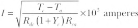 |
where:
| Tc | = | conductor temperature in degrees Celsius (°C) |
| Ta | = | ambient temperature in degrees Celsius (°C) |
| Rdc | = | dc resistance of 305 mm (1 ft) of conductor in microohms at temperature, Tc |
| Yc | = | component ac resistance resulting from skin effect and proximity effect |
| Rca | = | effective thermal resistance between conductor and surrounding ambient |
310.15 Ampacity Tables.
(A) General.
Ampacities for conductors rated 0 volts to 2000 volts shall be as specified in the Ampacity Table 310.16 through Table 310.21, as modified by 310.15(A) through (F) and 310.12. Under engineering supervision, ampacities of sizes not shown in ampacity tables for conductors meeting the general wiring requirements shall be permitted to be determined by interpolation of the adjacent conductors based on the conductor's circular-mil area.
The temperature correction and adjustment factors shall be permitted to be applied to the ampacity for the temperature rating of the conductor, if the corrected and adjusted ampacity does not exceed the ampacity for the temperature rating of the termination in accordance with 110.14(C).
Informational Note No. 1: Table 310.16 through Table 310.19 are application tables for use in determining conductor sizes on loads calculated in accordance with Part II, Part III, Part IV, or Part V of Article 220. Ampacities result from consideration of one or more of the following:
- Temperature compatibility with connected equipment, especially the connection points
- Coordination with circuit and system overcurrent protection
- Compliance with the requirements of product listings or certifications.
- Preservation of the safety benefits of established industry practices and standardized procedures
Informational Note No. 2: See Chapter 9, Table 8, Conductor Properties, for conductor area. Interpolation is based on the conductor circular-mil area and not the conductor overall area.
Informational Note No. 3: See 400.5 for the ampacities of flexible cords and cables. See 402.5 for the ampacities of fixture wires.
Informational Note No. 4: See Table 310.4(1) and Table 310.4(2) for explanation of type letters used in tables and for recognized sizes of conductors for the various conductor insulations. See 310.1 through 310.14 and the various articles of this Code for installation requirements. See Table 400.4, Table 400.5(A)(1), and Table 400.5(A)(2) for flexible cords.
(B) Ambient Temperature Correction Factors.
(1) General.
Ampacities for ambient temperatures other than those shown in the ampacity tables shall be corrected in accordance with Table 310.15(B)(1)(1) or Table 310.15(B)(1)(2), or shall be permitted to be calculated using Equation 310.15(B)(1).
| [310.15(B)(1)] |
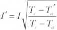 |
where:
| I' | = | ampacity corrected for ambient temperature |
| I | = | ampacity shown in the tables |
| Tc | = | temperature rating of conductor (°C) |
| Ta' | = | new ambient temperature (°C) |
| Ta | = | ambient temperature used in the table (°C) |
Table 310.15(B)(1)(1) Ambient Temperature Correction Factors Based on 30°C (86°F).
| For ambient temperatures other than 30°C (86°F), multiply the ampacities specified in the ampacity tables by the appropriate correction factor shown below. | ||||
|---|---|---|---|---|
| Ambient Temperature (°C) | Temperature Rating of Conductor | Ambient Temperature (°F) | ||
| 60°C | 75°C | 90°C | ||
| 10 or less | 1.29 | 1.20 | 1.15 | 50 or less |
| 11—15 | 1.22 | 1.15 | 1.12 | 51—59 |
| 16—20 | 1.15 | 1.11 | 1.08 | 60—68 |
| 21—25 | 1.08 | 1.05 | 1.04 | 69—77 |
| 26—30 | 1.00 | 1.00 | 1.00 | 78—86 |
| 31—35 | 0.91 | 0.94 | 0.96 | 87—95 |
| 36—40 | 0.82 | 0.88 | 0.91 | 96—104 |
| 41—45 | 0.71 | 0.82 | 0.87 | 105—113 |
| 46—50 | 0.58 | 0.75 | 0.82 | 114—122 |
| 51—55 | 0.41 | 0.67 | 0.76 | 123—131 |
| 56—60 | - | 0.58 | 0.71 | 132—140 |
| 61—65 | - | 0.47 | 0.65 | 141—149 |
| 66—70 | - | 0.33 | 0.58 | 150—158 |
| 71—75 | - | - | 0.50 | 159—167 |
| 76—80 | - | - | 0.41 | 168—176 |
| 81—85 | - | - | 0.29 | 177—185 |
Note: Table 310.15(B)(1)(1) shall be used with Table 310.16 and Table 310.17 as required.
Table 310.15(B)(1)(2) Ambient Temperature Correction Factors Based on 40°C (104°F).
| For ambient temperatures other than 40°C (104°F), multiply the ampacities specified in the ampacity tables by the appropriate correction factor shown below. | |||||||
|---|---|---|---|---|---|---|---|
| Ambient Temperature (°C) | Temperature Rating of Conductor | Ambient Temperature (°F) | |||||
| 60°C | 75°C | 90°C | 150°C | 200°C | 250°C | ||
| 10 or less | 1.58 | 1.36 | 1.26 | 1.13 | 1.09 | 1.07 | 50 or less |
| 11—15 | 1.50 | 1.31 | 1.22 | 1.11 | 1.08 | 1.06 | 51—59 |
| 16—20 | 1.41 | 1.25 | 1.18 | 1.09 | 1.06 | 1.05 | 60—68 |
| 21—25 | 1.32 | 1.2 | 1.14 | 1.07 | 1.05 | 1.04 | 69—77 |
| 26—30 | 1.22 | 1.13 | 1.10 | 1.04 | 1.03 | 1.02 | 78—86 |
| 31—35 | 1.12 | 1.07 | 1.05 | 1.02 | 1.02 | 1.01 | 87—95 |
| 36—40 | 1.00 | 1.00 | 1.00 | 1.00 | 1.00 | 1.00 | 96—104 |
| 41—45 | 0.87 | 0.93 | 0.95 | 0.98 | 0.98 | 0.99 | 105—113 |
| 46—50 | 0.71 | 0.85 | 0.89 | 0.95 | 0.97 | 0.98 | 114—122 |
| 51—55 | 0.50 | 0.76 | 0.84 | 0.93 | 0.95 | 0.96 | 123—131 |
| 56—60 | - | 0.65 | 0.77 | 0.90 | 0.94 | 0.95 | 132—140 |
| 61—65 | - | 0.53 | 0.71 | 0.88 | 0.92 | 0.94 | 141—149 |
| 66—70 | - | 0.38 | 0.63 | 0.85 | 0.90 | 0.93 | 150—158 |
| 71—75 | - | - | 0.55 | 0.83 | 0.88 | 0.91 | 159—167 |
| 76—80 | - | - | 0.45 | 0.80 | 0.87 | 0.90 | 168—176 |
| 81—90 | - | - | - | 0.74 | 0.83 | 0.87 | 177—194 |
| 91—100 | - | - | - | 0.67 | 0.79 | 0.85 | 195—212 |
| 101—110 | - | - | - | 0.60 | 0.75 | 0.82 | 213—230 |
| 111—120 | - | - | - | 0.52 | 0.71 | 0.79 | 231—248 |
| 121—130 | - | - | - | 0.43 | 0.66 | 0.76 | 249—266 |
| 131—140 | - | - | - | 0.30 | 0.61 | 0.72 | 267—284 |
| 141—160 | - | - | - | - | 0.50 | 0.65 | 285—320 |
| 161—180 | - | - | - | - | 0.35 | 0.58 | 321—356 |
| 181—200 | - | - | - | - | - | 0.49 | 357—392 |
| 201—225 | - | - | — | - | - | 0.35 | 393—437 |
(2) Rooftop.
For raceways or cables exposed to direct sunlight on or above rooftops where the distance above the roof to the bottom of the raceway or cable is less than 19 mm (3/4 in.), a temperature adder of 33°C (60°F) shall be added to the outdoor temperature to determine the applicable ambient temperature for application of the correction factors in Table 310.15(B)(1)(1) or Table 310.15(B)(1)(2).
Exception: Type XHHW-2 insulated conductors shall not be subject to this ampacity adjustment.
Informational Note: The ASHRAE Handbook - Fundamentals is one source for the ambient temperatures in various locations.
(C) Adjustment Factors.
(1) More Than Three Current-Carrying Conductors.
The ampacity of each conductor shall be reduced as shown in Table 310.15(C)(1) where the number of current-carrying conductors in a raceway or cable exceeds three, or where single conductors or multiconductor cables not installed in raceways are installed without maintaining spacing for a continuous length longer than 600 mm (24 in.). Each current-carrying conductor of a paralleled set of conductors shall be counted as a current-carrying conductor.
Where conductors of different systems, as provided in 300.3, are installed in a common raceway or cable, the adjustment factors shown in Table 310.15(C)(1) shall apply only to the number of power and lighting conductors.
Informational Note No. 1: See Informative Annex B for adjustment factors for more than three current-carrying conductors in a raceway or cable with load diversity.
Informational Note No. 2: See 366.23 for adjustment factors for conductors and ampacity for bare copper and aluminum bars in auxiliary gutters and 376.22(B) for adjustment factors for conductors in metal wireways.
- Where conductors are installed in cable trays, 392.80 shall apply.
- Adjustment factors shall not apply to conductors in raceways having a length not exceeding 600 mm (24 in.).
- Adjustment factors shall not apply to underground conductors entering or leaving an outdoor trench if those conductors have physical protection in the form of rigid metal conduit, intermediate metal conduit, rigid polyvinyl chloride conduit (PVC), or reinforced thermosetting resin conduit (RTRC) having a length not exceeding 3.05 m (10 ft), and if the number of conductors does not exceed four.
-
Adjustment factors shall not apply to Type AC cable or to Type MC cable under the following conditions:
- The cables do not have an overall outer jacket.
- Each cable has not more than three current-carrying conductors.
- The conductors are 12 AWG copper.
- Not more than 20 current-carrying conductors are installed without maintaining spacing, are stacked, or are supported on "bridle rings."
Exception to (4): If cables meeting the requirements in 310.15(C)(1)(d)(1) through (C)(1)(d)(3) with more than 20 current-carrying conductors are installed longer than 600 mm (24 in.) without maintaining spacing, are stacked, or are supported on bridle rings, a 60 percent adjustment factor shall be applied.
e 310.21 as required.Table 310.15(C)(1) Adjustment Factors for More Than Three Current-Carrying Conductors.
| Number of Conductors* | Percent of Values in Table 310.16 Through Table 310.19 as Adjusted for Ambient Temperature if Necessary |
|---|---|
| 4—6 | 80 |
| 7—9 | 70 |
| 10—20 | 50 |
| 21—30 | 45 |
| 31—40 | 40 |
| 41 and above | 35 |
*Number of conductors is the total number of conductors in the raceway or cable, including spare conductors. The count shall be adjusted in accordance with 310.15(E) and (F). The count shall not include conductors that are connected to electrical components that cannot be simultaneously energized.
(D) Bare or Covered Conductors.
Where bare or covered conductors are installed with insulated conductors, the temperature rating of the bare or covered conductor shall be equal to the lowest temperature rating of the insulated conductors for the purpose of determining ampacity.
(E) Neutral Conductor.
Neutral conductors shall be considered current carrying in accordance with any of the following:
- A neutral conductor that carries only the unbalanced current from other conductors of the same circuit shall not be required to be counted when applying the provisions of 310.15(C)(1).
- In a 3-wire circuit consisting of two phase conductors and the neutral conductor of a 4-wire, 3-phase, wye-connected system, the neutral conductor carries approximately the same current as the line-to-neutral load currents of the other conductors and shall be counted when applying 310.15(C)(1).
- On a 4-wire, 3-phase wye circuit where the major portion of the load consists of nonlinear loads, harmonic currents are present in the neutral conductor; the neutral conductor shall therefore be considered a current-carrying conductor.
310.16 Ampacities of Insulated Conductors in Raceway, Cable, or Earth (Directly Buried).
The ampacities shall be as specified in Table 310.16 where all of the following conditions apply:
(1) Conductors are rated 0 volts through 2000 volts.
(2) Conductors are rated 60°C (140°F), 75°C (167°F), or 90°C (194°F).
(3) Wiring is installed in a 30°C (86°F) ambient temperature.
(4) There are not more than three current-carrying conductors.
Table 310.16 Ampacities of Insulated Conductors with Not More Than Three Current-Carrying Conductors in Raceway, Cable, or Earth (Directly Buried).
| Size AWG or kcmil |
Temperature Rating of Conductor [See Table 310.4(1)] | Size AWG or kcmil |
|||||
|---|---|---|---|---|---|---|---|
| 60°C (140°F) | 75°C (167°F) | 90°C (194°F) | 60°C (140°F) | 75°C (167°F) | 90°C (194°F) | ||
| Types TW, UF | Types RHW, THHW, THW, THWN, XHHW, XHWN, USE, ZW |
Types TBS, SA, SIS, FEP, FEPB, MI, PFA, RHH, RHW-2, THHN, THHW, THW-2, THWN-2, USE-2, XHH, XHHW, XHHW-2, XHWN, XHWN-2, XHHN, Z, ZW-2 |
Types TW, UF | Types RHW, THHW, THW, THWN, XHHW, XHWN, USE |
Types TBS, SA, SIS, THHN, THHW, THW-2, THWN-2, RHH, RHW-2, USE-2, XHH, XHHW, XHHW-2, XHWN, XHWN-2, XHHN |
||
| COPPER | ALUMINUM OR COPPER-CLAD ALUMINUM | ||||||
| 18* | - | - | 14 | - | - | - | - |
| 16* | - | - | 18 | - | - | - | - |
| 14* | 15 | 20 | 25 | - | - | - | - |
| 12* | 20 | 25 | 30 | 15 | 20 | 25 | 12* |
| 10* | 30 | 35 | 40 | 25 | 30 | 35 | 10* |
| 8 | 40 | 50 | 55 | 35 | 40 | 45 | 8 |
| 6 | 55 | 65 | 75 | 40 | 50 | 55 | 6 |
| 4 | 70 | 85 | 95 | 55 | 65 | 75 | 4 |
| 3 | 85 | 100 | 115 | 65 | 75 | 85 | 3 |
| 2 | 95 | 115 | 130 | 75 | 90 | 100 | 2 |
| 1 | 110 | 130 | 145 | 85 | 100 | 115 | 1 |
| 1/0 | 125 | 150 | 170 | 100 | 120 | 135 | 1/0 |
| 2/0 | 145 | 175 | 195 | 115 | 135 | 150 | 2/0 |
| 3/0 | 165 | 200 | 225 | 130 | 155 | 175 | 3/0 |
| 4/0 | 195 | 230 | 260 | 150 | 180 | 205 | 4/0 |
| 250 | 215 | 255 | 290 | 170 | 205 | 230 | 250 |
| 300 | 240 | 285 | 320 | 195 | 230 | 260 | 300 |
| 350 | 260 | 310 | 350 | 210 | 250 | 280 | 350 |
| 400 | 280 | 335 | 380 | 225 | 270 | 305 | 400 |
| 500 | 320 | 380 | 430 | 260 | 310 | 350 | 500 |
| 600 | 350 | 420 | 475 | 285 | 340 | 385 | 600 |
| 700 | 385 | 460 | 520 | 315 | 375 | 425 | 700 |
| 750 | 400 | 475 | 535 | 320 | 385 | 435 | 750 |
| 800 | 410 | 490 | 555 | 330 | 395 | 445 | 800 |
| 900 | 435 | 520 | 585 | 355 | 425 | 480 | 900 |
| 1000 | 455 | 545 | 615 | 375 | 445 | 500 | 1000 |
| 1250 | 495 | 590 | 665 | 405 | 485 | 545 | 1250 |
| 1500 | 525 | 625 | 705 | 435 | 520 | 585 | 1500 |
| 1750 | 545 | 650 | 735 | 455 | 545 | 615 | 1750 |
| 2000 | 555 | 665 | 750 | 470 | 560 | 630 | 2000 |
Notes:
1. Section 310.15(B) shall be referenced for ampacity correction factors where the ambient temperature is other than 30°C (86°F).
2. Section 310.15(C)(1) shall be referenced for more than three current-carrying conductors.
3. Section 310.16 shall be referenced for conditions of use.
*Section 240.4(D) shall be referenced for conductor overcurrent protection limitations, except as modified elsewhere in the Code.
310.17 Ampacities of Single-Insulated Conductors in Free Air.
The ampacities shall be as specified in Table 310.17 where all of the following conditions apply:
(1) Conductors are rated 0 volts through 2000 volts.
(2) Conductors are rated 60°C (140°F), 75°C (167°F), or 90°C (194°F).
(3) Wiring is installed in a 30°C (86°F) ambient temperature.
Table 310.17 Ampacities of Single-Insulated Conductors in Free Air.
| Size AWG or kcmil |
Temperature Rating of Conductor [See Table 310.4(1)] | Size AWG or kcmil |
|||||
|---|---|---|---|---|---|---|---|
| 60°C (140°F) | 75°C (167°F) | 90°C (194°F) | 60°C (140°F) | 75°C (167°F) | 90°C (194°F) | ||
| Types TW, UF | Types RHW, THHW, THW, THWN, XHHW, XHWN, ZW |
Types TBS, SA, SIS, FEP, FEPB, MI, PFA, RHH, RHW-2, THHN, THHW, THW-2, THWN-2, USE-2, XHH, XHHW, XHHW-2, XHWN, XHWN-2, XHHN, Z, ZW-2 |
Types TW, UF | Types RHW, THHW, THW, THWN, XHHW, XHWN |
Types TBS, SA, SIS, THHN, THHW, THW-2, THWN-2, RHH, RHW-2, USE-2, XHH, XHHW, XHHW-2, XHWN, XHWN-2, XHHN |
||
| COPPER | ALUMINUM OR COPPER-CLAD ALUMINUM | ||||||
| 18 | - | - | 18 | - | - | - | - |
| 16 | - | - | 24 | - | - | - | - |
| 14* | 25 | 30 | 35 | - | - | - | - |
| 12* | 30 | 35 | 40 | 25 | 30 | 35 | 12* |
| 10* | 40 | 50 | 55 | 35 | 40 | 45 | 10* |
| 8 | 60 | 70 | 80 | 45 | 55 | 60 | 8 |
| 6 | 80 | 95 | 105 | 60 | 75 | 85 | 6 |
| 4 | 105 | 125 | 140 | 80 | 100 | 115 | 4 |
| 3 | 120 | 145 | 165 | 95 | 115 | 130 | 3 |
| 2 | 140 | 170 | 190 | 110 | 135 | 150 | 2 |
| 1 | 165 | 195 | 220 | 130 | 155 | 175 | 1 |
| 1/0 | 195 | 230 | 260 | 150 | 180 | 205 | 1/0 |
| 2/0 | 225 | 265 | 300 | 175 | 210 | 235 | 2/0 |
| 3/0 | 260 | 310 | 350 | 200 | 240 | 270 | 3/0 |
| 4/0 | 300 | 360 | 405 | 235 | 280 | 315 | 4/0 |
| 250 | 340 | 405 | 455 | 265 | 315 | 355 | 250 |
| 300 | 375 | 445 | 500 | 290 | 350 | 395 | 300 |
| 350 | 420 | 505 | 570 | 330 | 395 | 445 | 350 |
| 400 | 455 | 545 | 615 | 355 | 425 | 480 | 400 |
| 500 | 515 | 620 | 700 | 405 | 485 | 545 | 500 |
| 600 | 575 | 690 | 780 | 455 | 545 | 615 | 600 |
| 700 | 630 | 755 | 850 | 500 | 595 | 670 | 700 |
| 750 | 655 | 785 | 885 | 515 | 620 | 700 | 750 |
| 800 | 680 | 815 | 920 | 535 | 645 | 725 | 800 |
| 900 | 730 | 870 | 980 | 580 | 700 | 790 | 900 |
| 1000 | 780 | 935 | 1055 | 625 | 750 | 845 | 1000 |
| 1250 | 890 | 1065 | 1200 | 710 | 855 | 965 | 1250 |
| 1500 | 980 | 1175 | 1325 | 795 | 950 | 1070 | 1500 |
| 1750 | 1070 | 1280 | 1445 | 875 | 1050 | 1185 | 1750 |
| 2000 | 1155 | 1385 | 1560 | 960 | 1150 | 1295 | 2000 |
Notes:
1. Section 310.15(B) shall be referenced for ampacity correction factors where the ambient temperature is other than 30°C (86°F).
2. Section 310.17 shall be referenced for conditions of use.
*Section 240.4(D) shall be referenced for conductor overcurrent protection limitations, except as modified elsewhere in the Code.
310.18 Ampacities of Insulated Conductors in Raceway or Cable.
The ampacities shall be as specified in Table 310.18 where all of the following conditions apply:
(1) Conductors are rated 0 volts through 2000 volts.
(2) Conductors are rated 150°C (302°F), 200°C (392°F), or 250°C (482°F).
(3) Wiring is installed in a 40°C (104°F) ambient temperature.
(4) There are not more than three current-carrying conductors.
Table 310.18 Ampacities of Insulated Conductors with Not More Than Three Current-Carrying Conductors in Raceway or Cable.
| Size AWG or kcmil | Temperature Rating of Conductor [See Table 310.4(1)] | Size AWG or kcmil | |||
|---|---|---|---|---|---|
| 150°C (302°F) | 200°C (392°F) | 250°C (482°F) | 150°C (302°F) | ||
| Type Z | Types FEP, FEPB, PFA, SA |
Types PFAH, TFE | Type Z | ||
| COPPER | NICKEL OR NICKEL-COATED COPPER |
ALUMINUM OR COPPER-CLAD ALUMINUM |
|||
| 14 | 34 | 36 | 39 | - | 14 |
| 12 | 43 | 45 | 54 | 30 | 12 |
| 10 | 55 | 60 | 73 | 44 | 10 |
| 8 | 76 | 83 | 93 | 57 | 8 |
| 6 | 96 | 110 | 117 | 75 | 6 |
| 4 | 120 | 125 | 148 | 94 | 4 |
| 3 | 143 | 152 | 166 | 109 | 3 |
| 2 | 160 | 171 | 191 | 124 | 2 |
| 1 | 186 | 197 | 215 | 145 | 1 |
| 1/0 | 215 | 229 | 244 | 169 | 1/0 |
| 2/0 | 251 | 260 | 273 | 198 | 2/0 |
| 3/0 | 288 | 297 | 308 | 227 | 3/0 |
| 4/0 | 332 | 346 | 361 | 260 | 4/0 |
Notes:
1. Section 310.15(B) shall be referenced for ampacity correction factors where the ambient temperature is other than 40°C (104°F).
2. Section 310.15(C)(1) shall be referenced for more than three current-carrying conductors.
3. Section 310.18 shall be referenced for conditions of use.
310.19 Ampacities of Single-Insulated Conductors in Free Air.
The ampacities shall be as specified in Fable 310.19 where all of the following conditions apply:
(1) Conductors are rated 0 volts through 2000 volts.
(2) Conductors are rated up to 250°C (482°F).
(3) Wiring is installed in a 40°C (104°F) ambient temperature.
Table 310.19 Ampacities of Single-Insulated Conductors in Free Air.
| Size AWG or kcmil | Temperature Rating of Conductor [See Table 310.4(1)] | Size AWG or kcmil | |||
|---|---|---|---|---|---|
| 150°C (302°F) | 200°C (392°F) | 250°C (482°F) | 150°C (302°F) | ||
| Type Z | Types FEP, FEPB, PFA, SA |
Types PFAH, TFE | Type Z | ||
| COPPER | NICKEL OR NICKEL- COATED COPPER |
ALUMINUM OR COPPER-CLAD ALUMINUM |
|||
| 14 | 46 | 54 | 59 | - | 14 |
| 12 | 60 | 68 | 78 | 47 | 12 |
| 10 | 80 | 90 | 107 | 63 | 10 |
| 8 | 106 | 124 | 142 | 83 | 8 |
| 6 | 155 | 165 | 205 | 112 | 6 |
| 4 | 190 | 220 | 278 | 148 | 4 |
| 3 | 214 | 252 | 327 | 170 | 3 |
| 2 | 255 | 293 | 381 | 198 | 2 |
| 1 | 293 | 344 | 440 | 228 | 1 |
| 1/0 | 339 | 399 | 532 | 263 | 1/0 |
| 2/0 | 390 | 467 | 591 | 305 | 2/0 |
| 3/0 | 451 | 546 | 708 | 351 | 3/0 |
| 4/0 | 529 | 629 | 830 | 411 | 4/0 |
Notes:
1. Section 310.15(B) shall be referenced for ampacity correction factors where the ambient temperature is other than 40°C (104°F).
2. Section 310.19 shall be referenced for conditions of use.
310.20 Ampacities of Conductors Supported on a Messenger.
The ampacities shall be as specified in Table 310.20 where all of the following conditions apply:
(1) Conductors are rated 0 volts through 2000 volts.
(2) Conductors are rated 75°C (167°F) or 90°C (194°F).
(3) Wiring is installed in a 40°C (104°F) ambient temperature.
(4) There are not more than three single-insulated conductors.
Table 310.20 Ampacities of Conductors on a Messenger.
| Size AWG or kcmil | Temperature Rating of Conductor [See Table 310.4(1)] | Size AWG or kcmil | |||
|---|---|---|---|---|---|
| 75°C (167°F) | 90°C (194°F) | 75°C (167°F) | 90°C (194°F) | ||
| Types RHW, THHW, THW, THWN, XHHW, XHWN, ZW |
Types MI, THHN, THHW, THW-2, THWN-2, RHH, RHW-2, USE-2, XHHW, XHHW-2, XHWN-2, ZW-2 |
Types RHW, THW, THWN, THHW, XHHW, XHWN |
Types THHN, THHW, RHH, XHHW, RHW-2, XHHW-2, THW-2, THWN 2, XHWN-2, USE-2, ZW-2 |
||
| COPPER | ALUMINUM OR COPPER-CLAD ALUMINUM | ||||
| 8 | 57 | 66 | 44 | 51 | 8 |
| 6 | 76 | 89 | 59 | 69 | 6 |
| 4 | 101 | 117 | 78 | 91 | 4 |
| 3 | 118 | 138 | 92 | 107 | 3 |
| 2 | 135 | 158 | 106 | 123 | 2 |
| 1 | 158 | 185 | 123 | 144 | 1 |
| 1/0 | 183 | 214 | 143 | 167 | 1/0 |
| 2/0 | 212 | 247 | 165 | 193 | 2/0 |
| 3/0 | 245 | 287 | 192 | 224 | 3/0 |
| 4/0 | 287 | 335 | 224 | 262 | 4/0 |
| 250 | 320 | 374 | 251 | 292 | 250 |
| 300 | 359 | 419 | 282 | 328 | 300 |
| 350 | 397 | 464 | 312 | 364 | 350 |
| 400 | 430 | 503 | 339 | 395 | 400 |
| 500 | 496 | 580 | 392 | 458 | 500 |
| 600 | 553 | 647 | 440 | 514 | 600 |
| 700 | 610 | 714 | 488 | 570 | 700 |
| 750 | 638 | 747 | 512 | 598 | 750 |
| 800 | 660 | 773 | 532 | 622 | 800 |
| 900 | 704 | 826 | 572 | 669 | 900 |
| 1000 | 748 | 879 | 612 | 716 | 1000 |
Notes:
1. Section 310.15(B) shall be referenced for ampacity correction factors where the ambient temperature is other than 40°C (104°F).
2. Section 310.15(C)(1) shall be referenced for more than three current-carrying conductors.
3. Section 310.20 shall be referenced for conditions of use.
310.21 Ampacities of Bare or Covered Conductors in Free Air.
The ampacities shall be as specified in Table 310.21 where all of the following conditions apply:
- Wind velocity is 610 mm/sec (2 ft/sec).
- Conductors are 80°C (176°F) total conductor temperature.
- Wiring is installed in a 40°C (104°F) ambient temperature.
Table 310.21 Ampacities of Bare or Covered Conductors in Free Air.
| Copper Conductors | AAC Aluminum Conductors | ||||||
|---|---|---|---|---|---|---|---|
| Bare | Covered | Bare | Covered | ||||
| AWG or kcmil | Amperes | AWG or kcmil | Amperes | AWG or kcmil | Amperes | AWG or kcmil | Amperes |
| 8 | 98 | 8 | 103 | 8 | 76 | 8 | 80 |
| 6 | 124 | 6 | 130 | 6 | 96 | 6 | 101 |
| 4 | 155 | 4 | 163 | 4 | 121 | 4 | 127 |
| 2 | 209 | 2 | 219 | 2 | 163 | 2 | 171 |
| 1/0 | 282 | 1/0 | 297 | 1/0 | 220 | 1/0 | 231 |
| 2/0 | 329 | 2/0 | 344 | 2/0 | 255 | 2/0 | 268 |
| 3/0 | 382 | 3/0 | 401 | 3/0 | 297 | 3/0 | 312 |
| 4/0 | 444 | 4/0 | 466 | 4/0 | 346 | 4/0 | 364 |
| 250 | 494 | 250 | 519 | 266.8 | 403 | 266.8 | 423 |
| 300 | 556 | 300 | 584 | 336.4 | 468 | 336.4 | 492 |
| 500 | 773 | 500 | 812 | 397.5 | 522 | 397.5 | 548 |
| 750 | 1000 | 750 | 1050 | 477.0 | 588 | 477.0 | 617 |
| 1000 | 1193 | 1000 | 1253 | 556.5 | 650 | 556.5 | 682 |
| - | - | - | - | 636.0 | 709 | 636.0 | 744 |
| - | - | - | - | 795.0 | 819 | 795.0 | 860 |
| - | - | - | - | 954.0 | 920 | - | - |
| - | - | - | - | 1033.5 | 968 | 1033.5 | 1017 |
| - | - | - | - | 1272 | 1103 | 1272 | 1201 |
| - | - | - | - | 1590 | 1267 | 1590 | 1381 |
| - | - | - | - | 2000 | 1454 | 2000 | 1527 |
Note: Section 310.21 shall be referenced for conditions of use.
Article 312
Cabinets, Cutout Boxes, and Meter Socket Enclosures
312.1 Scope.
This article covers the installation and construction specifications of cabinets, cutout boxes, and meter socket enclosures. It does not apply to equipment operating at over 1000 volts, except as specifically referenced elsewhere in the Code.
312.2 Damp or Wet Locations.
In damp or wet locations, surface-type enclosures within the scope of this article shall be placed or equipped so as to prevent moisture or water from entering and accumulating within the cabinet or cutout box, and shall be mounted so there is at least 6-mm (1/4-in.) airspace between the enclosure and the wall or other supporting surface. Enclosures installed in wet locations shall be weatherproof. For enclosures in wet locations, raceways or cables entering above the level of uninsulated live parts shall use fittings listed for wet locations.
Exception: Nonmetallic enclosures shall be permitted to be installed without the airspace on a concrete, masonry, tile, or similar surface.
Informational Note: See 300.6 for protection against corrosion.
312.3 Position in Wall.
In walls of concrete, tile, or other noncombustible material, cabinets shall be installed so that the front edge of the cabinet is not set back of the finished surface more than 6 mm (1/4 in.). In walls constructed of wood or other combustible material, cabinets shall be flush with the finished surface or project therefrom.
312.4 Repairing Noncombustible Surfaces.
Noncombustible surfaces that are broken or incomplete shall be repaired so there will be no gaps or open spaces greater than 3 mm (1/8 in.) at the edge of the cabinet or cutout box employing a flush-type cover.
312.5 Cabinets, Cutout Boxes, and Meter Socket Enclosures.
Cable assemblies and insulated conductors entering enclosures within the scope of this article shall be protected from abrasion and shall comply with 312.5(A) through (C).
(B) Metal Cabinets, Cutout Boxes, and Meter Socket Enclosures.
Where metal enclosures within the scope of this article are installed with messenger-supported wiring, open wiring on insulators, or concealed knob-and-tube wiring, conductors shall enter through insulating bushings or, in dry locations, through flexible tubing extending from the last insulating support and firmly secured to the enclosure.
(C) Cables.
Where cable is used, each cable shall be secured to the cabinet, cutout box, or meter socket enclosure.
Exception No. 1: Cables with entirely nonmetallic sheaths shall be permitted to enter the top of a surface-mounted enclosure through one or more nonflexible raceways not less than 450 mm (18 in.) and not more than 3.0 m (10 ft) in length, provided all of the following conditions are met:
(1) Each cable is fastened within 300 mm (12 in.), measured along the sheath, of the outer end of the raceway.
(3) A fitting is provided on each end of the raceway to protect the cable(s) from abrasion and the fittings remain accessible after installation.
(4) The raceway is sealed or plugged at the outer end using approved means so as to prevent access to the enclosure through the raceway.
(5) The cable sheath is continuous through the raceway and extends into the enclosure beyond the fitting not less than 6 mm (1/4 in.).
(6) The raceway is fastened at its outer end and at other points in accordance with the applicable article.
(7) Where installed as conduit or tubing, the cable fill does not exceed the amount that would be permitted for complete conduit or tubing systems by Table 1 of Chapter 9 of this Code and all applicable notes thereto. Note 2 to the tables in Chapter 9 does not apply to this condition.
Informational Note: See Chapter 9, Table 1, including Note 9, for allowable cable fill in circular raceways. See 310.15(C)(1) for required ampacity reductions for multiple cables installed in a common raceway.
Exception No. 2: Single conductors and multiconductor cables shall be permitted to enter enclosures in accordance with 392.46(A) or (B).
312.6 Deflection of Conductors.
Conductors at terminals or conductors entering or leaving cabinets, cutout boxes, and meter socket enclosures shall comply with 312.6(A) through (C).
Exception: Wire-bending space in enclosures for motor controllers with provisions for one or two wires per terminal shall comply with 430.10(B).
(A) Width of Wiring Gutters.
Conductors shall not be deflected within a cabinet or cutout box unless a gutter having a width in accordance with Table 312.6(A) is provided. Conductors in parallel in accordance with 310.10(G) shall be judged on the basis of the number of conductors in parallel.
Table 312.6(A) Minimum Wire-Bending Space at Terminals and Minimum Width of Wiring Gutters.
| Wire Size (AWG or kcmil) | Wires per Terminal | ||||||||||
|---|---|---|---|---|---|---|---|---|---|---|---|
| All Other Conductors | Compact Stranded AA-8000 Aluminum Alloy Conductors (See Note 2) |
1 | 2 | 3 | 4 | 5 | |||||
| mm | in. | mm | in. | mm | in. | mm | in. | mm | in. | ||
| 14—10 | 12—8 | Not specified | - | - | - | - | - | - | - | - | |
| 8—6 | 6—4 | 38.1 | 11/2 | - | - | - | - | - | - | - | - |
| 4—3 | 2—1 | 50.8 | 2 | - | - | - | - | - | - | - | - |
| 2 | 1/0 | 63.5 | 21/2 | - | - | - | - | - | - | - | - |
| 1 | 2/0 | 76.2 | 3 | - | - | - | - | - | - | - | - |
| 1/0—2/0 | 3/0—4/0 | 88.9 | 31/2 | 127 | 5 | 178 | 7 | - | - | - | - |
| 3/0—4/0 | 250—300 | 102 | 4 | 152 | 6 | 203 | 8 | - | - | - | - |
| 250 | 350 | 114 | 41/2 | 152 | 6 | 203 | 8 | 254 | 10 | - | - |
| 300—350 | 400—500 | 127 | 5 | 203 | 8 | 254 | 10 | 305 | 12 | - | - |
| 400—500 | 600—750 | 152 | 6 | 203 | 8 | 254 | 10 | 305 | 12 | 356 | 14 |
| 600—700 | 800—1000 | 203 | 8 | 254 | 10 | 305 | 12 | 356 | 14 | 406 | 16 |
| 750—900 | - | 203 | 8 | 305 | 12 | 356 | 14 | 406 | 16 | 457 | 18 |
| 1000—1250 | - | 254 | 10 | - | - | - | - | - | - | - | - |
| 1500—2000 | - | 305 | 12 | - | - | - | - | - | - | - | - |
Notes:
1. Bending space at terminals shall be measured in a straight line from the end of the lug or wire connector (in the direction that the wire leaves the terminal) to the wall, barrier, or obstruction.
2. This column shall be permitted to be used to determine the minimum wire-bending space for compact stranded aluminum conductors in sizes up to 1000 kcmil and manufactured using AA-8000 series electrical grade aluminum alloy conductor material in accordance with 310.3(B). The minimum width of the wire gutter space shall be determined using the all other conductors value in this table.
(B) Wire-Bending Space at Terminals.
(1) Conductors Not Entering or Leaving Opposite Wall.
Table 312.6(A) shall apply where the conductor does not enter or leave the enclosure through the wall opposite its terminal.
(2) Conductors Entering or Leaving Opposite Wall.
Table 312.6(B)(2) shall apply where the conductor does enter or leave the enclosure through the wall opposite its terminal.
Exception No. 1: Where the distance between the wall and its terminal is in accordance with Table 312.6(A), a conductor shall be permitted to enter or leave an enclosure through the wall opposite its terminal, provided the conductor enters or leaves the enclosure where the gutter joins an adjacent gutter that has a width that conforms to Table 312.6(B)(2) for the conductor.
Exception No. 2: A conductor not larger than 350 kcmil shall be permitted to enter or leave an enclosure containing only a meter socket(s) through the wall opposite its terminal, provided the distance between the terminal and the opposite wall is not less than that specified in Table 312.6(A) and the terminal is a lay-in type or removable lug with integral mounting tang, where the terminal is either of the following:
(1) Directed toward the opening in the enclosure and within a 45-degree angle of directly facing the enclosure wall
Table 312.6(B)(2) Minimum Wire-Bending Space at Terminals.
| Wire Size (AWG or kcmil) | Wires per Terminal | ||||||||
|---|---|---|---|---|---|---|---|---|---|
| All Other Conductors | Compact Stranded AA-8000 Aluminum Alloy Conductors (See Note 3) |
1 | 2 | 3 | 4 or more | ||||
| mm | in. | mm | in. | mm | in. | mm | in. | ||
| 14—10 | 12—8 | Not specified | - | - | - | - | - | ||
| 8 | 6 | 38.1 | 11/2 | - | - | - | - | - | |
| 6 | 4 | 50.8 | 2 | - | - | - | - | - | |
| 4 | 2 | 76.2 | 3 | - | - | - | - | - | |
| 3 | 1 | 76.2 | 3 | - | - | - | - | - | |
| 2 | 1/0 | 88.9 | 31/2 | - | - | - | - | - | |
| 1 | 2/0 | 114 | 41/2 | - | - | - | - | - | |
| 1/0 | 3/0 | 140 | 51/2 | 140 | 51/2 | 178 | 7 | - | - |
| 2/0 | 4/0 | 152 | 6 | 152 | 6 | 190 | 71/2 | - | - |
| 3/0 | 250 | 165a | 61/2a | 165a | 61/2a | 203 | 8 | - | - |
| 4/0 | 300 | 178b | 7b | 190c | 71/2c | 216a | 81/2a | - | - |
| 250 | 350 | 216d | 81/2d | 216d | 81/2d | 229b | 9b | 254 | 10 |
| 300 | 400 | 254e | 10e | 254d | 10d | 279b | 11b | 305 | 12 |
| 350 | 500 | 305e | 12e | 305e | 12e | 330e | 13e | 356d | 14d |
| 400 | 600 | 330e | 13e | 330e | 13e | 356e | 14e | 381e | 15e |
| 500 | 700—750 | 356e | 14e | 356e | 14e | 381e | 15e | 406e | 16e |
| 600 | 800—900 | 381e | 15e | 406e | 16e | 457e | 18e | 483e | 19e |
| 700 | 1000 | 406e | 16e | 457e | 18e | 508e | 20e | 559e | 22e |
| 750 | - | 432e | 17e | 483e | 19e | 559e | 22e | 610e | 24e |
| 800 | - | 457 | 18 | 508 | 20 | 559 | 22 | 610 | 24 |
| 900 | - | 483 | 19 | 559 | 22 | 610 | 24 | 610 | 24 |
| 1000 | - | 508 | 20 | - | - | - | - | ||
| 1250 | - | 559 | 22 | - | - | - | - | ||
| 1500 | - | 610 | 24 | - | - | - | - | ||
| 1750 | - | 610 | 24 | - | - | - | - | ||
| 2000 | — | 610 | 24 | - | - | - | - | ||
Notes:
1. Bending space at terminals shall be measured in a straight line from the end of the lug or wire connector in a direction perpendicular to the enclosure wall.
2. For removable and lay-in wire terminals intended for only one wire, bending space shall be permitted to be reduced by the following number of millimeters (inches):
a12.7 mm (1/2 in.)
b25.4 mm (1 in.)
c38.1 mm (11/2 in.)
d50.8 mm (2 in.)
e76.2 mm (3 in.)
312.7 Space in Enclosures.
Cabinets and cutout boxes shall have approved space to accommodate all conductors installed in them without crowding.
312.8 Switch and Overcurrent Device Enclosures.
The wiring space within enclosures for switches and overcurrent devices shall be permitted for other wiring and equipment subject to limitations for specific equipment as provided in 312.8(A) and (B).
(A) Splices, Taps, and Feed-Through Conductors.
The wiring space of enclosures for switches or overcurrent devices shall be permitted for conductors feeding through, spliced, or tapping off to other enclosures, switches, or overcurrent devices where all of the following conditions are met:
- The total of all conductors installed at any cross section of the wiring space does not exceed 40 percent of the cross-sectional area of that space.
- The total area of all conductors, splices, and taps installed at any cross section of the wiring space does not exceed 75 percent of the cross-sectional area of that space.
- The bending space for conductors 4 AWG and larger complies with 314.28(A)(2).
- A warning label complying with 110.21(B) is applied to the enclosure that identifies the closest disconnecting means for any feed-through conductors.
(B) Power Monitoring or Energy Management Equipment.
The wiring space of enclosures for switches or overcurrent devices shall be permitted to contain power monitoring or energy management equipment in accordance with 312.8(B)(1) through (B)(3).
(1) Identification.
Power monitoring or energy management equipment shall either be identified as a field installable accessory as part of the listed equipment or be a listed kit evaluated for field installation in switch or overcurrent device enclosures.
(3) Conductors.
Conductors used exclusively for control or instrumentation circuits shall comply with either 312.8(B)(3)(a) or (B)(3)(b).
- Conductors shall comply with 724.49.
- Conductors smaller than 18 AWG, but not smaller than 22 AWG for a single conductor and 26 AWG for a multiconductor cable, shall be permitted to be used where the conductors and cable assemblies meet all of the following conditions:
- Are enclosed within raceways or routed along one or more walls of the enclosure and secured at intervals that do not exceed 250 mm (10 in.)
- Are secured within 250 mm (10 in.) of terminations
- Are secured to prevent contact with current carrying components within the enclosure
- Are rated for the system voltage and not less than 600 volts
- Have a minimum insulation temperature rating of 90°C
312.9 Side or Back Wiring Spaces or Gutters.
Cabinets and cutout boxes shall be provided with back-wiring spaces, gutters, or wiring compartments as required by 312.101(C) and (D).
312.10 Screws or Other Fasteners.
Screws or other fasteners installed in the field that enter wiring spaces shall be as provided by or specified by the manufacturer or shall comply with the following as applicable:
312.100 Material.
(A) Metal Cabinets and Cutout Boxes.
Metal enclosures within the scope of this article shall be protected both inside and outside against corrosion.
(B) Strength.
The design and construction of enclosures within the scope of this article shall be such as to secure ample strength and rigidity. If constructed of sheet steel, the metal thickness shall not be less than 1.35 mm (0.053 in.) uncoated.
(C) Nonmetallic Cabinets.
Nonmetallic cabinets shall be listed, or they shall be submitted for approval prior to installation.
312.101 Spacing.
(A) General.
Spacing within cabinets and cutout boxes shall provide approved spacing for the distribution of wires and cables placed in them and for a separation between metal parts of devices and apparatus mounted within them in accordance with 312.101(A)(1), (A)(2), and (A)(3).
(1) Base.
Other than at points of support, there shall be an airspace of at least 1.59 mm (0.0625 in.) between the base of the device and the wall of any metal cabinet or cutout box in which the device is mounted.
(2) Doors.
There shall be an airspace of at least 25.4 mm (1.00 in.) between any live metal part, including live metal parts of enclosed fuses, and the door.
Exception: Where the door is lined with an approved insulating material or is of a thickness of metal not less than 2.36 mm (0.093 in.) uncoated, the airspace shall not be less than 12.7 mm (0.500 in.).
(3) Live Parts.
There shall be an airspace of at least 12.7 mm (0.500 in.) between the walls, back, gutter partition, if of metal, or door of any cabinet or cutout box and the nearest exposed current-carrying part of devices mounted within the cabinet where the voltage does not exceed 250. This spacing shall be increased to at least 25.4 mm (1.00 in.) for voltages of 251 to 1000, nominal.
Exception: Where the conditions in 312.101(A)(2), Exception, are met, the airspace for nominal voltages from 251 to 600 shall be permitted to be not less than 12.7 mm (0.500 in.).
(B) Switch Clearance.
Cabinets and cutout boxes shall be deep enough to allow the closing of the doors when 30-ampere branch-circuit panelboard switches are in any position, when combination cutout switches are in any position, or when other single-throw switches are opened as far as their construction permits.
(C) Wiring Space.
Cabinets and cutout boxes that contain devices or apparatus connected within the cabinet or box to more than eight conductors, including those of branch circuits, meter loops, feeder circuits, power circuits, and similar circuits, but not including the supply circuit or a continuation thereof, shall have back-wiring spaces or one or more side-wiring spaces, side gutters, or wiring compartments.
(D) Wiring Space - Enclosure.
Side-wiring spaces, side gutters, or side-wiring compartments of cabinets and cutout boxes shall be made tight enclosures by means of covers, barriers, or partitions extending from the bases of the devices contained in the cabinet, to the door, frame, or sides of the cabinet.
Exception: Side-wiring spaces, side gutters, and side-wiring compartments of cabinets shall not be required to be made tight enclosures where those side spaces contain only conductors that enter the cabinet directly opposite to the devices where they terminate.
Partially enclosed back-wiring spaces shall be provided with covers to complete the enclosure. Wiring spaces that are required by 312.101(C) and are exposed when doors are open shall be provided with covers to complete the enclosure. Where space is provided for feed-through conductors and for splices as required in 312.8, additional barriers shall not be required.
Article 314
Outlet, Device, Pull, and Junction Boxes; Conduit Bodies; Fittings; And Handhole Enclosures
314.1 Scope.
This article covers the installation and use of all boxes and conduit bodies used as outlet, device, junction, or pull boxes, depending on their use, and handhole enclosures. Cast metal, sheet metal, nonmetallic, and other boxes such as FS, FD, and larger boxes are not classified as conduit bodies. This article also includes installation requirements for fittings used to join raceways and to connect raceways and cables to boxes and conduit bodies.
314.2 Round Boxes.
Round boxes shall not be used where conduits or connectors requiring the use of locknuts or bushings are to be connected to the side of the box.
314.3 Nonmetallic Boxes.
Nonmetallic boxes shall be permitted only with open wiring on insulators, concealed knob-and-tube wiring, cabled wiring methods with entirely nonmetallic sheaths, flexible cords, and nonmetallic raceways.
Exception No. 1: Where internal bonding means are provided between all entries, nonmetallic boxes shall be permitted to be used with metal raceways or metal-armored cables.
Exception No. 2: Where integral bonding means with a provision for attaching an equipment bonding jumper inside the box are provided between all threaded entries in nonmetallic boxes listed for the purpose, nonmetallic boxes shall be permitted to be used with metal raceways or metal-armored cables.
314.4 Metal Boxes.
Metal boxes shall be grounded and bonded in accordance with Parts I, IV, V, VI, VII, and X of Article 250 as applicable, except as permitted in 250.112(I).
314.5 Screws or Other Fasteners.
Screws or other fasteners installed in the field that enter wiring spaces shall be as provided by or specified by the manufacturer or shall comply with the following as applicable:
- Screws shall be machine type with blunt ends.
- Other fasteners shall have blunt ends.
- Screws attaching a cover shall extend no more than 10 mm (3/8 in.).
- Screws or other fasteners, other than in (3), penetrating a cover shall extend no more than 8 mm (5/16 in.).
- Screws or other fasteners penetrating a wall of a box exceeding 1650 cm3 (100 in.3) shall extend no more than 6 mm (1/4 in.), or more than 11 mm (7/16 in.) if located within 10 mm (3/8 in.) of an adjacent box wall.
- Screws or other fasteners penetrating the wall of a box not exceeding 1650 cm3 (100 in.3) and not covered in 314.23(B)(1) shall be made flush with the box interior.
- Screws or other fasteners penetrating the wall of a conduit body shall be made flush with the conduit body interior.
Exception to (3) through (6): A screw shall be permitted to be longer if the end of the screw is protected with an approved means.
314.15 Damp or Wet Locations.
In damp or wet locations, boxes, conduit bodies, outlet box hoods, and fittings shall be placed or equipped so as to prevent moisture from entering or accumulating within the box, conduit body, or fitting. Boxes, conduit bodies, outlet box hoods, and fittings installed in wet locations shall be listed for use in wet locations. Approved drainage openings not smaller than 3 mm (1/8 in.) and not larger than 6 mm (1/4 in.) in diameter shall be permitted to be installed in the field in boxes or conduit bodies listed for use in damp or wet locations. For installation of listed drain fittings, larger openings are permitted to be installed in the field in accordance with manufacturer's instructions.
Informational Note No. 1: See 314.27(B) for boxes in floors.
Informational Note No. 2: See 300.6 for protection against corrosion.
314.16 Number of Conductors in Outlet, Device, and Junction Boxes, and Conduit Bodies.
Boxes and conduit bodies shall be of an approved size to provide free space for all enclosed conductors. In no case shall the volume of the box, as calculated in 314.16(A), be less than the fill calculation as calculated in 314.16(B). The minimum volume for conduit bodies shall be as calculated in 314.16(C).
This section shall not apply to terminal housings supplied with motors or generators.
Informational Note: See 430.12 for volume requirements of motor or generator terminal housings.
Boxes and conduit bodies enclosing conductors 4 AWG or larger shall also comply with 314.28. Outlet and device boxes shall also comply with 314.24.
(A) Box Volume Calculations.
The volume of a wiring enclosure (box) shall be the total volume of the assembled sections and, where used, the space provided by plaster rings, domed covers, extension rings, and so forth, that are marked with their volume or are made from boxes the dimensions of which are listed in Table 314.16(A). Where a box is provided with one or more securely installed barriers, the volume shall be apportioned to each of the resulting spaces. Each barrier, if not marked with its volume, shall be considered to take up 8.2 cm3 (1/2 in.3) if metal, and 16.4 cm3 (1.0 in.3) if nonmetallic.
Table 314.16(A) Metal Boxes.
| Box Trade Size | Minimum Volume | Maximum Number of Conductors* (arranged by AWG size) | |||||||||
|---|---|---|---|---|---|---|---|---|---|---|---|
| mm | in. | cm3 | in.3 | 18 | 16 | 14 | 12 | 10 | 8 | 6 | |
| 100 × 32 | (4 × 11/4) | round/octagonal | 205 | 12.5 | 8 | 7 | 6 | 5 | 5 | 4 | 2 |
| 100 × 38 | (4 × 11/2) | round/octagonal | 254 | 15.5 | 10 | 8 | 7 | 6 | 6 | 5 | 3 |
| 100 × 54 | (4 × 21/8) | round/octagonal | 353 | 21.5 | 14 | 12 | 10 | 9 | 8 | 7 | 4 |
| 100 × 32 | (4 × 11/4) | square | 295 | 18.0 | 12 | 10 | 9 | 8 | 7 | 6 | 3 |
| 100 × 38 | (4 × 11/2) | square | 344 | 21.0 | 14 | 12 | 10 | 9 | 8 | 7 | 4 |
| 100 × 54 | (4 × 21/8) | square | 497 | 30.3 | 20 | 17 | 15 | 13 | 12 | 10 | 6 |
| 120 × 32 | (411/16× 11/4) | square | 418 | 25.5 | 17 | 14 | 12 | 11 | 10 | 8 | 5 |
| 120 × 38 | (411/16× 11/2) | square | 484 | 29.5 | 19 | 16 | 14 | 13 | 11 | 9 | 5 |
| 120 × 54 | (411/16× 21/8) | square | 689 | 42.0 | 28 | 24 | 21 | 18 | 16 | 14 | 8 |
| 75 × 50 × 38 | (3 × 2 × 11/2) | device | 123 | 7.5 | 5 | 4 | 3 | 3 | 3 | 2 | 1 |
| 75 × 50 × 50 | (3 × 2 × 2) | device | 164 | 10.0 | 6 | 5 | 5 | 4 | 4 | 3 | 2 |
| 75 × 50 × 57 | (3 × 2 × 21/4) | device | 172 | 10.5 | 7 | 6 | 5 | 4 | 4 | 3 | 2 |
| 75 × 50 × 65 | (3 × 2 × 21/4) | device | 205 | 12.5 | 8 | 7 | 6 | 5 | 5 | 4 | 2 |
| 75 × 50 × 70 | (3 × 2 × 23/4) | device | 230 | 14.0 | 9 | 8 | 7 | 6 | 5 | 4 | 2 |
| 75 × 50 × 90 | (3 × 2 × 31/2) | device | 295 | 18.0 | 12 | 10 | 9 | 8 | 7 | 6 | 3 |
| 100 × 54 × 38 | (4 × 21/8 × 11/2) | device | 169 | 10.3 | 6 | 5 | 5 | 4 | 4 | 3 | 2 |
| 100 × 54 × 48 | (4 × 21/8 × 17/8) | device | 213 | 13.0 | 8 | 7 | 6 | 5 | 5 | 4 | 2 |
| 100 × 54 × 54 | (4 × 21/8 × 21/8) | device | 238 | 14.5 | 9 | 8 | 7 | 6 | 5 | 4 | 2 |
| 95 × 50 × 65 | (33/4 × 2 × 21/2) | masonry box/gang | 230 | 14.0 | 9 | 8 | 7 | 6 | 5 | 4 | 2 |
| 95 × 50 × 90 | (33/4 × 2 × 31/2) | masonry box/gang | 344 | 21.0 | 14 | 12 | 10 | 9 | 8 | 7 | 4 |
| min. 44.5 depth | FS - single cover/gang (13/4) | 221 | 13.5 | 9 | 7 | 6 | 6 | 5 | 4 | 2 | |
| min. 60.3 depth | FD - single cover/gang (23/8) | 295 | 18.0 | 12 | 10 | 9 | 8 | 7 | 6 | 3 | |
| min. 44.5 depth | FS - multiple cover/gang (13/4) | 295 | 18.0 | 12 | 10 | 9 | 8 | 7 | 6 | 3 | |
| min. 60.3 depth | FD - multiple cover/gang (23/8) | 395 | 24.0 | 16 | 13 | 12 | 10 | 9 | 8 | 4 | |
*Where no volume allowances are required by 314.16(B)(2) through (B)(6).
(1) Standard Boxes.
The volumes of standard boxes that are not marked with their volume shall be as given in Table 314.16(A).
(2) Other Boxes.
Boxes 1650 cm3 (100 in.3) or less, other than those described in Table 314.16(A), and nonmetallic boxes shall be durably and legibly marked by the manufacturer with their volume(s). Boxes described in Table 314.16(A) that have a volume larger than is designated in the table shall be permitted to have their volume marked as required by this section.
(B) Box Fill Calculations.
The volumes in 314.16(B)(1) through (B)(6), as applicable, shall be added together. No allowance shall be required for small fittings such as locknuts and bushings. Each space within a box installed with a barrier shall be calculated separately.
(1) Conductor Fill.
Each conductor that originates outside the box and terminates or is spliced within the box shall be counted once, and each conductor that passes through the box without splice or termination shall be counted once. Each loop or coil of unbroken conductor not less than twice the minimum length required for free conductors in 300.14 shall be counted twice. The conductor fill shall be calculated using Table 314.16(B)(1). A conductor, no part of which leaves the box, shall not be counted.
Exception: An equipment grounding conductor or conductors or not over four fixture wires smaller than 14 AWG, or both, shall be permitted to be omitted from the calculations where they enter a box from a domed luminaire or similar canopy and terminate within that box.
Table 314.16(B)(1) Volume Allowance Required per Conductor.
| Size of Conductor (AWG) | Free Space Within Box for Each Conductor | |
|---|---|---|
| cm3 | in.3 | |
| 18 | 24.6 | 1.50 |
| 16 | 28.7 | 1.75 |
| 14 | 32.8 | 2.00 |
| 12 | 36.9 | 2.25 |
| 10 | 41.0 | 2.50 |
| 8 | 49.2 | 3.00 |
| 6 | 81.9 | 5.00 |
(2) Clamp Fill.
Where one or more internal cable clamps, whether factory or field supplied, are present in the box, a single volume allowance in accordance with Table 314.16(B)(1) shall be made based on the largest conductor present in the box. No allowance shall be required for a cable connector with its clamping mechanism outside the box.
(4) Device or Equipment Fill.
For each yoke or strap containing one or more devices or equipment, a double volume allowance in accordance with Table 314.16(B)(1) shall be made for each yoke or strap based on the largest conductor connected to a device(s) or equipment supported by that yoke or strap. A device or utilization equipment wider than a single 50 mm (2 in.) device box as described in Table 314.16(A) shall have double volume allowances provided for each gang required for mounting.
(5) Equipment Grounding Conductor Fill.
Where up to four equipment grounding conductors enter a box, a single volume allowance in accordance with Table 314.16(B)(1) shall be made based on the largest equipment grounding conductor entering the box. A 1/4 volume allowance shall be made for each additional equipment grounding conductor that enters the box, based on the largest equipment grounding conductor entering the box.
(C) Conduit Bodies.
(1) General.
Conduit bodies enclosing 6 AWG conductors or smaller, other than short-radius conduit bodies as described in 314.16(C)(3). shall have a cross-sectional area not less than twice the cross-sectional area of the largest conduit or tubing to which they can be attached. The maximum number of conductors permitted shall be the maximum number permitted by Table 1 of Chapter 9 for the conduit or tubing to which it is attached.
(2) With Splices, Taps, or Devices.
Only those conduit bodies that are durably and legibly marked by the manufacturer with their volume shall be permitted to contain splices, taps, or devices. The maximum number of conductors shall be calculated in accordance with 314.16(B). Conduit bodies shall be supported in a rigid and secure manner.
(3) Short Radius Conduit Bodies.
Conduit bodies such as capped elbows and service-entrance elbows that enclose conductors 6 AWG or smaller, and are only intended to enable the installation of the raceway and the contained conductors, shall not contain splices, taps, or devices and shall be of an approved size to provide free space for all conductors enclosed in the conduit body.
314.17 Conductors and Cables Entering Boxes, Conduit Bodies, or Fittings.
Conductors entering boxes, conduit bodies, or fittings shall be protected from abrasion. Conductors and cables shall comply with 314.17(A) through (C).
(B) Boxes and Conduit Bodies.
The installation of the conductors and cables in boxes and conduit bodies shall comply with 314.17(B)(1) through (B)(4).
(1) Conductors Entering Through Individual Holes or Through Flexible Tubing.
For messenger-supported wiring, open wiring on insulators, or concealed knob-and-tube wiring, the conductors shall enter the box through individual holes. In installations where metal boxes or conduit bodies are used with conductors unprotected by flexible tubing, the individual openings shall be provided with insulating bushings. Where flexible tubing is used to enclose the conductors, the tubing shall extend from the last insulating support to not less than 6 mm (1/4 in.) inside the box or conduit body and 6 mm (1/4 in.) beyond the end of any cable clamp. The wiring method shall be secured to the box or conduit body.
(2) Cables Entering Through Cable Clamps.
Where cable assemblies with nonmetallic sheaths are used, the sheath shall extend not less than 6 mm (1/4 in.) inside the box and 6 mm (1/4 in.) beyond the end of any cable clamp. Except as covered in 300.15(C), the wiring method shall be secured to the box or conduit body.
Exception: Where nonmetallic-sheathed cable is used with single gang nonmetallic boxes not larger than a nominal size 57 mm × 100 mm (21/4 in. × 4 in.) mounted in walls or ceilings, and where the cable is fastened within 200 mm (8 in.) of the box measured along the sheath and where the sheath extends through a cable knockout not less than 6 mm (1/4 in.), securing the cable to the box shall not be required. Multiple cable entries shall be permitted in a single cable knockout opening.
(3) Conductors and Cables Entering Through Raceways.
Where the raceway is complete between boxes, conduit bodies, or both and encloses individual conductors or nonmetallic cable assemblies or both, the conductors or cable assemblies shall not be required to be additionally secured. Where raceways enclose cable assemblies as covered in 300.15(C), the cable assembly shall not be required to be additionally secured within the box or conduit body.
(4) Temperature Limitation.
Nonmetallic boxes and conduit bodies shall be suitable for the lowest temperature-rated conductor entering the box or conduit body.
314.19 Boxes Enclosing Flush Devices or Flush Equipment.
Boxes used to enclose flush devices or flush equipment shall be of such design that the devices or equipment will be completely enclosed on the back and sides, and substantial support for the devices or equipment will be provided. Screws for supporting the box shall not also be used to attach a device or equipment.
314.20 Flush-Mounted Installations.
Installations within or behind a surface of concrete, tile, gypsum, plaster, or other noncombustible material, including boxes employing a flush-type cover or faceplate, shall be made so that the front edge of the box, plaster ring, extension ring, or listed extender will not be set back of the finished surface more than 6 mm (1/4 in.).
Installations within a surface of wood or other combustible surface material, boxes, plaster rings, extension rings, or listed extenders shall extend to the finished surface or project therefrom.
314.21 Repairing Noncombustible Surfaces.
Noncombustible surfaces that are broken or incomplete around boxes employing a flush-type cover or faceplate shall be repaired so there will be no gaps or open spaces greater than 3 mm (1/8 in.) at the edge of the box.
314.22 Surface Extensions.
Surface extensions shall be made by mounting and mechanically securing an extension ring over the box. Equipment grounding shall be in accordance with Part VI of Article 250.
Exception: A surface extension shall be permitted to be made from the cover of a box where the cover is designed so it is unlikely to fall off or be removed if its securing means becomes loose. The wiring method shall be flexible for an approved length that permits removal of the cover and provides access to the box interior and shall be arranged so that any grounding continuity is independent of the connection between the box and cover.
314.23 Supports.
Enclosures within the scope of this article shall be supported in accordance with 314.23(A) through (H) as applicable.
(A) Surface Mounting.
An enclosure mounted on a building or other surface shall be rigidly and securely fastened in place. If the surface does not provide rigid and secure support, additional support in accordance with this section shall be provided.
(B) Structural Mounting.
An enclosure supported from a structural member or from grade shall be rigidly supported either directly or by using a metal, polymeric, or wood brace.
(1) Nails and Screws.
Nails and screws, where used as a fastening means, shall secure boxes by using brackets on the outside of the enclosure, or by using mounting holes in the back or in one or more sides of the enclosure, or they shall pass through the interior within 6 mm (1/4 in.) of the back or ends of the enclosure. Screws shall not be permitted to pass through the box unless exposed threads in the box are protected using approved means to avoid abrasion of conductor insulation. Mounting holes made in the field shall be approved.
(2) Braces.
Metal braces shall be protected against corrosion and formed from metal that is not less than 0.51 mm (0.020 in.) thick uncoated. Wood braces shall have a cross section not less than nominal 25 mm × 50 mm (1 in. × 2 in.). Wood braces in wet locations shall be treated for the conditions. Polymeric braces shall be identified as being suitable for the use.
(C) Mounting in Finished Surfaces.
An enclosure mounted in a finished surface shall be rigidly secured thereto by clamps, anchors, or fittings identified for the application.
(D) Suspended Ceilings.
An enclosure mounted to structural or supporting elements of a suspended ceiling shall be not more than 1650 cm3 (100 in.3) in size and shall be securely fastened in place in accordance with either 314.23(D)(1) or (D)(2).
(1) Framing Members.
An enclosure shall be fastened to the framing members by mechanical means such as bolts, screws, or rivets, or by the use of clips or other securing means identified for use with the type of ceiling framing member(s) and enclosure(s) employed. The framing members shall be supported in an approved manner and securely fastened to each other and to the building structure.
(2) Support Wires.
The installation shall comply with 300.11(B). The enclosure shall be secured, using identified methods, to ceiling support wire(s), including any additional support wire(s) installed for ceiling support. Support wire(s) used for enclosure support shall be fastened at each end so as to be taut within the ceiling cavity.
(E) Raceway-Supported Enclosure, Without Devices, Luminaires, or Lampholders.
An enclosure that does not contain a device(s), other than splicing devices, or supports a luminaire(s), a lampholder, or other equipment and is supported by entering raceways shall not exceed 1650 cm3 (100 in.3) in size. It shall have threaded entries or identified hubs. It shall be supported by two or more conduits threaded wrenchtight into the enclosure or hubs. Each conduit shall be secured within 900 mm (3 ft) of the enclosure, or within 450 mm (18 in.) of the enclosure if all conduit entries are on the same side.
Exception: The following wiring methods shall be permitted to support a conduit body of any size, including a conduit body constructed with only one conduit entry, provided that the trade size of the conduit body is not larger than the largest trade size of the conduit or tubing:
(1) Intermediate metal conduit, IMC
(2) Rigid metal conduit, RMC
(3) Rigid polyvinyl chloride conduit, PVC
(4) Reinforced thermosetting resin conduit, RTRC
(5) Electrical metallic tubing, EMT
(F) Raceway-Supported Enclosures, With Devices, Luminaires, or Lampholders.
An enclosure that contains a device(s), other than splicing devices, or supports a luminaire(s), a lampholder, or other equipment and is supported by entering raceways shall not exceed 1650 cm3 (100 in.3) in size. It shall have threaded entries or identified hubs. It shall be supported by two or more conduits threaded wrenchtight into the enclosure or hubs. Each conduit shall be secured within 450 mm (18 in.) of the enclosure.
Exception No. 1: Rigid metal or intermediate metal conduit shall be permitted to support a conduit body of any size, including a conduit body constructed with only one conduit entry, provided the trade size of the conduit body is not larger than the largest trade size of the conduit.
Exception No. 2: An unbroken length(s) of rigid or intermediate metal conduit shall be permitted to support a box used for luminaire or lampholder support, or to support a wiring enclosure that is an integral part of a luminaire and used in lieu of a box in accordance with 300.15(B), where all of the following conditions are met:
(1) The conduit is securely fastened at a point so that the length of conduit beyond the last point of conduit support does not exceed 900 mm (3 ft).
(2) The unbroken conduit length before the last point of conduit support is 300 mm (12 in.) or greater, and that portion of the conduit is securely fastened at some point not less than 300 mm (12 in.) from its last point of support.
(3) Where accessible to unqualified persons, the luminaire or lampholder, measured to its lowest point, is at least 2.5 m (8 ft) above grade or standing area and at least 900 mm (3 ft) measured horizontally to the 2.5 m (8 ft) elevation from windows, doors, porches, fire escapes, or similar locations.
(4) A luminaire supported by a single conduit does not exceed 300 mm (12 in.) in any direction from the point of conduit entry.
(5) The weight supported by any single conduit does not exceed 9 kg (20 lb).
(6) At the luminaire or lampholder end, the conduit(s) is threaded wrenchtight into the box, conduit body, integral wiring enclosure, or identified hubs. Where, a box or conduit body is used for support, the luminaire shall be secured directly to the box or conduit body, or through a threaded conduit nipple not over 75 mm (3 in.) long.
(G) Enclosures in Concrete or Masonry.
An enclosure supported by embedment shall be identified as suitably protected from corrosion and securely embedded in concrete or masonry.
(H) Pendant Boxes.
(2) Conduit.
A box supporting lampholders or luminaires, or wiring enclosures within luminaires used in lieu of boxes in accordance with 300.15(B), shall be supported by rigid or intermediate metal conduit stems. For stems longer than 450 mm (18 in.), the stems shall be connected to the wiring system with listed swivel hangers suitable for the location. At the luminaire end, the conduit(s) shall be threaded wrenchtight into the box, wiring enclosure, or identified hubs.
Where supported by only a single conduit, the threaded joints shall be prevented from loosening by the use of setscrews or other effective means, or the luminaire, at any point, shall be at least 2.5 m (8 ft) above grade or standing area and at least 900 mm (3 ft) measured horizontally to the 2.5 m (8 ft) elevation from windows, doors, porches, fire escapes, or similar locations. A luminaire supported by a single conduit shall not exceed 300 mm (12 in.) in any horizontal direction from the point of conduit entry.
314.24 Dimensions of Boxes.
Outlet and device boxes shall have approved dimensions to allow equipment installed within them to be mounted properly and without likelihood of damage to conductors within the box.
(A) Depth of Outlet Boxes Without Enclosed Devices or Utilization Equipment.
Outlet boxes that do not enclose devices or utilization equipment shall have a minimum internal depth of 12.7 mm (1/2 in.).
(B) Depth of Outlet and Device Boxes With Enclosed Devices or Utilization Equipment.
Outlet and device boxes that enclose devices or utilization equipment shall have a minimum internal depth that accommodates the rearward projection of the equipment and the size of the conductors that supply the equipment. The internal depth shall include, where used, that of any extension boxes, plaster rings, or raised covers. The internal depth shall comply with 314.24(B)(1) through (B)(5) as applicable.
(1) Large Equipment.
Boxes that enclose devices or utilization equipment that projects more than 48 mm (17/8 in.) rearward from the mounting plane of the box shall have a depth that is not less than the depth of the equipment plus 6 mm (1/4 in.).
(2) Conductors Larger Than 4 AWG.
Boxes that enclose devices or utilization equipment supplied by conductors larger than 4 AWG shall be identified for their specific function.
Exception: Devices or utilization equipment supplied by conductors larger than 4 AWG shall be permitted to be mounted on or in junction and pull boxes larger than 1650 cm3 (100 in.3) if the spacing at the terminals meets the requirements of 312.6.
(3) Conductors 8, 6, or 4 AWG.
Boxes that enclose devices or utilization equipment supplied by 8, 6, or 4 AWG conductors shall have an internal depth that is not less than 52.4 mm (21/16 in.).
(4) Conductors 12 or 10 AWG.
Boxes that enclose devices or utilization equipment supplied by 12 or 10 AWG conductors shall have an internal depth that is not less than 30.2 mm (13/16 in.). Where the equipment projects rearward from the mounting plane of the box by more than 25 mm (1 in.), the box shall have a depth not less than that of the equipment plus 6 mm (1/4 in.). Where wiring enters the center portion of the rear of a box opposite to the equipment, the minimum clearance shall be increased to 13 mm (1/2 in.)
(5) Conductors 14 AWG and Smaller.
Boxes that enclose devices or utilization equipment supplied by 14 AWG or smaller conductors shall have a depth that is not less than 23.8 mm (15/16 in.).
Exception: Under any of the conditions specified in 314.24(B)(1) through (B)(5), devices or utilization equipment that is listed to be installed with specified boxes shall be permitted.
(C) Clearances for Side-Wiring Entrances.
314.25 Covers and Canopies.
In completed installations, each box shall have a cover, faceplate, lampholder, or luminaire canopy, except where the installation complies with 410.24(B). Conduit body enclosures shall be installed with a cover, lampholder, or device. Screws used for the purpose of attaching covers, or other equipment, to the box shall be either machine screws matching the thread gauge and size that is integral to the box or shall be in accordance with the manufacturer's instructions.
(A) Nonmetallic or Metal Covers and Plates.
Nonmetallic or metal covers and plates shall be permitted. Where metal covers or plates are used, they shall be connected to the equipment grounding conductor in accordance with 250.110.
(C) Flexible Cord Pendants.
Covers of outlet boxes and conduit bodies having holes through which flexible cord pendants pass shall be provided with identified bushings or shall have smooth, well-rounded surfaces on which the cords can bear. So-called hard rubber or composition bushings shall not be used.
314.27 Outlet Boxes.
(A) Boxes at Luminaire or Lampholder Outlets.
Outlet boxes or fittings designed for the support of luminaires and lampholders, and installed as required by 314.23, shall be permitted to support a luminaire or lampholder.
(1) Vertical Surface Outlets.
Boxes used at luminaire or lampholder outlets in or on a vertical surface shall be identified and marked on the interior of the box to indicate the maximum weight of the luminaire that is permitted to be supported by the box if other than 23 kg (50 lb).
Exception: A vertically mounted luminaire or lampholder weighing not more than 3 kg (6 lb) shall be permitted to be supported on other boxes or plaster rings that are secured to other boxes, provided that the luminaire or its supporting yoke, or the lampholder, is secured to the box with no fewer than two No. 6 or larger screws.
(2) Ceiling Outlets.
At every outlet used exclusively for lighting, the box shall be designed or installed so that a luminaire or lampholder can be attached. Boxes shall be required to support a luminaire weighing a minimum of 23 kg (50 lb). A luminaire that weighs more than 23 kg (50 lb) shall be supported independently of the outlet box, unless the outlet box is listed for not less than the weight to be supported. The interior of the box shall be marked by the manufacturer to indicate the maximum weight the box shall be permitted to support.
(B) Floor Boxes.
Boxes listed specifically for this application shall be used for receptacles located in the floor.
Exception: Where the authority having jurisdiction judges them free from likely exposure to physical damage, moisture, and dirt, boxes located in elevated floors of show windows and similar locations shall be permitted to be other than those listed for floor applications. Receptacles and covers shall be listed as an assembly for this type of location.
(C) Boxes at Ceiling-Suspended (Paddle) Fan Outlets.
Outlet boxes or outlet box systems used as the sole support of a ceiling-suspended (paddle) fan shall be listed, shall be marked by their manufacturer on the interior of the box as suitable for this purpose, and shall not support ceiling-suspended (paddle) fans that weigh more than 32 kg (70 lb). For outlet boxes or outlet box systems designed to support ceiling-suspended (paddle) fans that weigh more than 16 kg (35 lb), the required marking shall include the maximum weight to be supported.
Outlet boxes mounted in the ceilings of habitable rooms of dwelling occupancies in a location acceptable for the installation of a ceiling-suspended (paddle) fan shall comply with one of the following:
- Listed for the sole support of ceiling-suspended (paddle) fans
- Installed so as to allow direct access through the box to structural framing capable of supporting a ceiling-suspended (paddle) fan without removing the box
(D) Utilization Equipment.
Boxes used for the support of utilization equipment other than ceiling-suspended (paddle) fans shall meet the requirements of 314.27(A) for the support of a luminaire that is the same size and weight.
Exception: Utilization equipment weighing not more than 3 kg (6 lb) shall be permitted to be supported on other boxes or plaster rings that are secured to other boxes, provided the equipment or its supporting yoke is secured to the box with no fewer than two No. 6 or larger screws.
(E) Weight-Supporting Ceiling Receptacles (WSCR) and Weight-Supporting Attachment Fittings (WSAF).
Outlet boxes required in 314.27 shall be permitted to support listed weight-supporting ceiling receptacles (WSCR). A WSCR shall be used in combination with compatible weight-supporting attachment fittings (WSAF) that are identified for the support of equipment within the weight and mounting orientation limits of the listing. Where the WSCR is installed, it shall be included in the box fill calculation covered in 314.16(B)(4).
Listed WSCR used in combination with compatible WSAF shall be permitted to be installed in outlet boxes for the sole support of ceiling-suspended (paddle) fans, in accordance with 314.27(C).
Informational Note: See ANSI/NEMA WD-6, American National Standard for Wiring Devices—Dimensional Specifications, for standard configurations of weight-supporting ceiling receptacles and weight-supporting attachment fittings.
314.28 Pull and Junction Boxes and Conduit Bodies.
Boxes and conduit bodies used as pull or junction boxes shall comply with 314.28(A) through (E).
Exception: Terminal housings supplied with motors shall comply with the provisions of 430.12.
(A) Minimum Size.
For raceways containing conductors of 4 AWG or larger that are required to be insulated, and for cables containing conductors of 4 AWG or larger, the minimum dimensions of pull or junction boxes installed in a raceway or cable run shall comply with 314.28(A)(1) through (A)(3). Where an enclosure dimension is to be calculated based on the diameter of entering raceways, the diameter shall be the metric designator (trade size) expressed in the units of measurement employed.
(1) Straight Pulls.
In straight pulls, the length of the box or conduit body shall not be less than eight times the metric designator (trade size) of the largest raceway.
(2) Angle or U Pulls, or Splices.
Where splices or where angle or U pulls are made, the distance between each raceway entry inside the box or conduit body and the opposite wall of the box or conduit body shall not be less than six times the metric designator (trade size) of the largest raceway in a row. This distance shall be increased for additional entries by the amount of the sum of the diameters of all other raceway entries in the same row on the same wall of the box. Each row shall be calculated individually, and the single row that provides the maximum distance shall be used.
Exception: Where a raceway or cable entry is in the wall of a box or conduit body opposite a removable cover, the distance from that wall to the cover shall be permitted to comply with the distance required for one wire per terminal in Table 312.6(A).
The distance between raceway entries enclosing the same conductor shall not be less than six times the metric designator (trade size) of the larger raceway.
When transposing cable size into raceway size in 314.28(A)(1) and (A)(2), the minimum metric designator (trade size) raceway required for the number and size of conductors in the cable shall be used.
(3) Smaller Dimensions.
Listed boxes or listed conduit bodies of dimensions less than those required in 314.28(A)(1) and (A)(2) shall be permitted for installations of combinations of conductors that are less than the maximum conduit or tubing fill (of conduits or tubing being used) permitted by Table 1 of Chapter 9.
Listed conduit bodies of dimensions less than those required in 314.28(A)(2), and having a radius of the curve to the centerline not less than that indicated in Table 2 of Chapter 9 for one-shot and full-shoe benders, shall be permitted for installations of combinations of conductors permitted by Table 1 of Chapter 9. These conduit bodies shall be marked to show they have been specifically evaluated in accordance with this provision.
Where the permitted combinations of conductors for which the box or conduit body has been listed are less than the maximum conduit or tubing fill permitted by Table 1 of Chapter 9, the box or conduit body shall be permanently marked with the maximum number and maximum size of conductors permitted. For other conductor sizes and combinations, the total cross-sectional area of the fill shall not exceed the cross-sectional area of the conductors specified in the marking, based on the type of conductor identified as part of the product listing.
Informational Note: Unless otherwise specified, the applicable product standards evaluate the fill markings covered here based on conductors with Type XHHW insulation.
(B) Conductors in Pull or Junction Boxes.
In pull boxes or junction boxes having any dimension over 1.8 m (6 ft), all conductors shall be cabled or racked up in an approved manner.
(C) Covers.
All pull boxes, junction boxes, and conduit bodies shall be provided with covers compatible with the box or conduit body construction and suitable for the conditions of use. Where used, metal covers shall comply with the grounding requirements of 250.110.
(D) Permanent Barriers.
Where permanent barriers are installed in a box, each section shall be considered as a separate box.
(E) Power Distribution Blocks.
Power distribution blocks shall be permitted in pull and junction boxes over 1650 cm3 (100 in.3) for connections of conductors where installed in boxes and where the installation complies with 314.28(E)(1) through (E)(5).
Exception: Equipment grounding terminal bars shall be permitted in smaller enclosures.
(2) Size.
In addition to the overall size requirement in the first sentence of 314.28(A)(2), the power distribution block shall be installed in a box with dimensions not smaller than specified in the installation instructions of the power distribution block.
(4) Live Parts.
Power distribution blocks shall not have uninsulated live parts exposed within a box, whether or not the box cover is installed.
314.29 Boxes, Conduit Bodies, and Handhole Enclosures to Be Accessible.
Boxes, conduit bodies, and handhole enclosures shall be installed so that wiring and devices contained in the boxes, conduit bodies, or handhole enclosures can be rendered accessible in accordance with 314.29(A) and (B).
(B) Underground.
Underground boxes and handhole enclosures shall be installed so they are accessible without excavating sidewalks, paving, earth, or other substance that is to be used to establish the finished grade.
Exception: Listed boxes and handhole enclosures shall be permitted where covered by gravel, light aggregate, or noncohesive granulated soil if their location is effectively described and accessible for excavation. The location description shall be available to those authorized to access, maintain, or inspect the wiring.
314.30 Handhole Enclosures.
Handhole enclosures shall be designed and installed to withstand all loads likely to be imposed on them. They shall be identified for use in underground systems.
Informational Note: See ANSI/SCTE 77-2013, Specification for Underground Enclosure Integrity, for additional information on deliberate and nondeliberate traffic loading that can be expected to bear on underground enclosures.
(A) Size.
Handhole enclosures shall be sized in accordance with 314.28(A) for conductors operating at 1000 volts or below, and in accordance with 314.71 for conductors operating at over 1000 volts. For handhole enclosures without bottoms where the provisions of 314.28(A)(2), Exception, or 314.71(B)(1), Exception No. 1, apply, the measurement to the removable cover shall be taken from the end of the conduit or cable assembly.
(B) Wiring Entries.
Underground raceways and cable assemblies entering a handhole enclosure shall extend into the enclosure, but they shall not be required to be mechanically connected to the enclosure.
(C) Enclosed Wiring.
All enclosed conductors and any splices or terminations, if present, shall be listed as suitable for wet locations.
(D) Covers.
Handhole enclosure covers shall have an identifying mark or logo that prominently identifies the function of the enclosure, such as "electric." Handhole enclosure covers shall require the use of tools to open, or they shall weigh over 45 kg (100 lb). Metal covers and other exposed conductive surfaces shall be bonded in accordance with 250.92 if the conductors in the handhole are service conductors, or in accordance with 250.96(A) if the conductors in the handhole are feeder or branch-circuit conductors.
314.70 General.
(A) Pull and Junction Boxes.
Where pull and junction boxes are used on systems over 1000 volts, the installation shall comply with Part III and with the following general provisions of this article:
(B) Conduit Bodies.
Where conduit bodies are used on systems over 1000 volts, the installation shall comply with Part III and with the following general provisions of this article:
- Part I, 314.4, and 314.5
- Part II, 314.15; 314.17; 314.23(A), (E), or (G); 314.28(A)(3); and 314.29
- Part III, 314.100(A) and 314.101
314.71 Size of Pull and Junction Boxes, Conduit Bodies, and Handhole Enclosures.
Pull and junction boxes and handhole enclosures shall provide approved space and dimensions for the installation of conductors, and they shall comply with the specific requirements of this section. Conduit bodies shall be permitted if they meet the dimensional requirements for boxes.
(B) For Angle or U Pulls.
(1) Distance to Opposite Wall.
The distance between each cable or conductor entry inside the box and the opposite wall of the box shall not be less than 36 times the outside diameter, over sheath, of the largest cable or conductor. This distance shall be increased for additional entries by the amount of the sum of the outside diameters, over sheath, of all other cables or conductor entries through the same wall of the box.
Exception No. 1: Where a conductor or cable entry is in the wall of a box opposite a removable cover, the distance from that wall to the cover shall be permitted to be not less than the bending radius for the conductors as provided in 305.5.
Exception No. 2: Where cables are nonshielded and not lead covered, the distance of 36 times the outside diameter shall be permitted to be reduced to 24 times the outside diameter.
(2) Distance Between Entry and Exit.
The distance between a cable or conductor entry and its exit from the box shall not be less than 36 times the outside diameter, over sheath, of that cable or conductor.
Exception: Where cables are nonshielded and not lead covered, the distance of 36 times the outside diameter shall be permitted to be reduced to 24 times the outside diameter.
(C) Removable Sides.
One or more sides of any pull box shall be removable.
314.72 Construction and Installation Requirements.
(A) Corrosion Protection.
Boxes shall be made of material inherently resistant to corrosion or shall be suitably protected, both internally and externally, by enameling, galvanizing, plating, or other means.
(B) Passing Through Partitions.
Suitable bushings, shields, or fittings having smooth, rounded edges shall be provided where conductors or cables pass through partitions and at other locations where necessary.
(D) Wiring Is Accessible.
Boxes and conduit bodies shall be installed so that the conductors are accessible without removing any fixed part of the building or structure. Working space shall be provided in accordance with 110.34.
(E) Suitable Covers.
Boxes shall be closed by suitable covers securely fastened in place. Underground box covers that weigh over 45 kg (100 lb) shall be considered meeting this requirement. Covers for boxes shall be permanently marked "DANGER - HIGH VOLTAGE - KEEP OUT." The marking shall be on the outside of the box cover and shall be readily visible. Letters shall be block type and at least 13 mm (1/2 in.) in height.
(F) Suitable for Expected Handling.
Boxes and their covers shall be capable of withstanding the handling to which they are likely to be subjected.
314.100 Metal Boxes, Conduit Bodies, and Fittings.
(A) Corrosion Resistant.
Metal boxes, conduit bodies, and fittings shall be corrosion resistant or shall be well-galvanized, enameled, or otherwise properly coated inside and out to prevent corrosion.
(B) Thickness of Metal.
Sheet steel boxes not over 1650 cm3 (100 in.3) in size shall be made from steel not less than 1.59 mm (0.0625 in.) thick. The wall of a malleable iron box or conduit body and a die-cast or permanent-mold cast aluminum, brass, bronze, or zinc box or conduit body shall not be less than 2.38 mm (3/32 in.) thick. Other cast metal boxes or conduit bodies shall have a wall thickness not less than 3.17 mm (1/8 in.).
Exception No. 1: Listed boxes and conduit bodies shown to have equivalent strength and characteristics shall be permitted to be made of thinner or other metals.
Exception No. 2: The walls of listed short radius conduit bodies, as covered in 314.16(C)(2), shall be permitted to be made of thinner metal.
(C) Metal Boxes Over 1650 cm3 (100 in.3).
Metal boxes over 1650 cm3 (100 in.3) in size shall be constructed so as to be of ample strength and rigidity. If of sheet steel, the metal thickness shall not be less than 1.35 mm (0.053 in.) uncoated.
(D) Equipment Grounding Conductor Provisions.
A means shall be provided in each metal box for the connection of an equipment grounding conductor. The means shall be permitted to be a tapped hole or equivalent.
314.101 Covers.
Metal covers shall be of the same material as the box or conduit body with which they are used, or they shall be lined with firmly attached insulating material that is not less than 0.79 mm (1/32 in.) thick, or they shall be listed for the purpose. Metal covers shall be the same thickness as the boxes or conduit body for which they are used, or they shall be listed for the purpose. Covers of porcelain or other approved insulating materials shall be permitted if of such form and thickness as to afford the required protection and strength.
314.102 Bushings.
Covers of outlet boxes and conduit bodies having holes through which flexible cord pendants pass shall be provided with approved bushings or shall have smooth, well-rounded surfaces on which the cord will bear. Where individual conductors pass through a metal cover, a separate hole equipped with a bushing of suitable insulating material shall be provided for each conductor. Such separate holes shall be connected by a slot as required by 300.20.
314.103 Nonmetallic Boxes.
Provisions for supports or other mounting means for nonmetallic boxes shall be outside of the box, or the box shall be constructed so as to prevent contact between the conductors in the box and the supporting screws.
314.104 Marking.
All boxes and conduit bodies, covers, extension rings, plaster rings, and the like shall be durably and legibly marked with the manufacturer's name or trademark.
Article 315
Medium Voltage Conductors, Cable, Cable Joints, and Cable Terminations
315.1 Scope.
This article covers the use, installation, construction specifications, and ampacities for Type MV medium voltage conductors, cable, cable joints, and cable terminations. This article includes voltages from 2001 volts to 35,000 volts ac, nominal and 2001 volts to 2500 volts dc, nominal.
315.6 Listing Requirements.
Type MV cables, type MV cable joints, type MV cable terminations, connectors, and associated fittings shall be listed. The listing requirement for Type MV cable joints, cable terminations, and connectors shall be effective January 1, 2026.
315.10 Constructions and Applications.
(A) Conductor Application and Insulation.
Conductor application and insulation shall comply with Table 315.10(A).
Table 315.10(A) Conductor Application and Insulation Rated 2001 Volts and Higher.
| Trade Name | Type Letter | Maximum Operating Temperature | Application Provision | Insulation | Outer Covering |
|---|---|---|---|---|---|
| Medium voltage solid dielectric | MV-90 MV-105* | 90°C 105°C | Dry or wet locations | Thermoplastic or thermosetting | Jacket, sheath, or armor |
*Where design conditions require maximum conductor temperatures above 90°C.
(B) Thickness of Insulation and Jacket for Nonshielded Insulated Conductors.
Thickness of insulation and jacket for nonshielded solid dielectric insulated conductors rated 2001 volts to 5000 volts shall comply with Table 315.10(B).
Table 315.10(B) Thickness of Insulation and Jacket for Nonshielded Solid Dielectric Insulated Conductors Rated 2001 Volts to 5000 Volts.
| Conductor Size (AWG or kcmil) | Dry Locations, Single Conductor | Wet or Dry Locations | ||||||||||
|---|---|---|---|---|---|---|---|---|---|---|---|---|
| Without Jacket Insulation | With Jacket | Single Conductor | Multiconductor Insulation* | |||||||||
| Insulation | Jacket | Insulation | Jacket | |||||||||
| mm | mils | mm | mils | mm | mils | mm | mils | mm | mils | mm | mils | |
| 8 | 2.79 | 110 | 2.29 | 90 | 0.76 | 30 | 3.18 | 125 | 2.03 | 80 | 2.29 | 90 |
| 6 | 2.79 | 110 | 2.29 | 90 | 0.76 | 30 | 3.18 | 125 | 2.03 | 80 | 2.29 | 90 |
| 4—2 | 2.79 | 110 | 2.29 | 90 | 1.14 | 45 | 3.18 | 125 | 2.03 | 80 | 2.29 | 90 |
| 1—2/0 | 2.79 | 110 | 2.29 | 90 | 1.14 | 45 | 3.18 | 125 | 2.03 | 80 | 2.29 | 90 |
| 3/0—4/0 | 2.79 | 110 | 2.29 | 90 | 1.65 | 65 | 3.18 | 125 | 2.41 | 95 | 2.29 | 90 |
| 213—500 | 3.05 | 120 | 2.29 | 90 | 1.65 | 65 | 3.56 | 140 | 2.79 | 110 | 2.29 | 90 |
| 501—750 | 3.30 | 130 | 2.29 | 90 | 1.65 | 65 | 3.94 | 155 | 3.18 | 125 | 2.29 | 90 |
| 751—1000 | 3.30 | 130 | 2.29 | 90 | 1.65 | 65 | 3.94 | 155 | 3.18 | 125 | 2.29 | 90 |
| 1001—1250 | 3.56 | 140 | 2.92 | 115 | 1.65 | 65 | 4.32 | 170 | 3.56 | 140 | 2.92 | 115 |
| 1251—1500 | 3.56 | 140 | 2.92 | 115 | 2.03 | 80 | 4.32 | 170 | 3.56 | 140 | 2.92 | 115 |
| 1501—2000 | 3.56 | 140 | 2.92 | 115 | 2.03 | 80 | 4.32 | 170 | 3.94 | 155 | 3.56 | 140 |
*Under a common overall covering such as a jacket, sheath, or armor.
(C) Thickness of Insulation for Shielded Insulated Conductors.
Thickness of insulation for shielded solid dielectric insulated conductors rated 2001 volts to 35,000 volts shall comply with Table 315.10(C) and 315.10(C)(1) through (C)(3).
Table 315.10(C) Thickness of Insulation for Shielded Solid Dielectric Insulated Conductors Rated 2001 Volts to 35,000 Volts.
| Conductor Size (AWG or kcmil) | 2001—5000 Volts | 5001—8000 Volts | 8001—15,000 Volts | 15,001—25,000 Volts | ||||||||||||||||
|---|---|---|---|---|---|---|---|---|---|---|---|---|---|---|---|---|---|---|---|---|
| 100 Percent Insulation Level | 100 Percent Insulation Level | 133 Percent Insulation Level | 173 Percent Insulation Level | 100 Percent Insulation Level | 133 Percent Insulation Level | 173 Percent Insulation Level | 100 Percent Insulation Level | 133 Percent Insulation Level | 173 Percent Insulation Level | |||||||||||
| mm | mils | mm | mils | mm | mils | mm | mils | mm | mils | mm | mils | mm | mils | mm | mils | mm | mils | mm | mils | |
| 8 | 2.29 | 90 | - | - | - | - | - | - | - | - | - | - | - | - | - | - | - | - | - | - |
| 6—4 | 2.29 | 90 | 2.92 | 115 | 3.56 | 140 | 4.45 | 175 | - | - | - | - | - | - | - | - | - | - | - | - |
| 2 | 2.29 | 90 | 2.92 | 115 | 3.56 | 140 | 4.45 | 175 | 445 | 175 | 5.59 | 220 | 6.60 | 260 | - | - | - | - | - | - |
| 1 | 2.29 | 90 | 2.92 | 115 | 3.56 | 140 | 4.45 | 175 | 4.45 | 175 | 5.59 | 220 | 6.60 | 260 | 6.60 | 260 | 8.13 | 320 | 10.67 | 420 |
| 1/0—2000 | 2.29 | 90 | 2.92 | 115 | 3.56 | 140 | 4.45 | 175 | 4.45 | 175 | 5.59 | 220 | 6.60 | 260 | 6.60 | 260 | 8.13 | 320 | 10.67 | 420 |
| Conductor Size (AWG or kcmil) | 25,001—28,000 Volts | 28,001—35,000 Volts | ||||||||||
|---|---|---|---|---|---|---|---|---|---|---|---|---|
| 100 Percent Insulation Level | 133 Percent Insulation Level | 173 Percent Insulation Level | 100 Percent Insulation Level | 133 Percent Insulation Level | 173 Percent Insulation Level | |||||||
| mm | mils | mm | mils | mm | mils | mm | mils | mm | mils | mm | mils | |
| 1 | 7.11 | 280 | 8.76 | 345 | 11.30 | 445 | - | - | - | - | - | - |
| 1/0—2000 | 7.11 | 280 | 8.76 | 345 | 11.30 | 445 | 8.76 | 345 | 10.67 | 420 | 14.73 | 580 |
(1) 100 Percent Insulation Level.
Cables shall be permitted to be applied where the system is provided with relay protection such that ground faults will be cleared as rapidly as possible but, in any case, within 1 minute. These cables are applicable to cable installations that are on grounded systems and shall be permitted to be used on other systems provided the above clearing requirements are met in completely de-energizing the faulted section.
(2) 133 Percent Insulation Level.
Cables shall be permitted to be applied in situations where the clearing time requirements of the 100 percent level category cannot be met and the faulted section will be de-energized in a time not exceeding 1 hour. Cable shall be permitted to be used in 100 percent insulation level applications where the installation requires additional insulation.
(3) 173 Percent Insulation Level.
Cables shall be permitted to be applied under all of the following conditions:
- In industrial establishments where the conditions of maintenance and supervision ensure only qualified persons service the installation
- Where the fault clearing time requirements of the 133 percent level category cannot be met
- Where an orderly shutdown is required to protect equipment and personnel
- Where the faulted section will be de-energized in an orderly shutdown
Cables shall be permitted to be used in 100 percent or 133 percent insulation level applications where the installation requires additional insulation.
Informational Note: See UL 1072, Medium-Voltage Power Cable, ANSI/ICEA S-93-639, American National Standard for 5-46kV Shielded Power Cable for Use in the Transmission and Distribution of Electric Energy, and ICEA S-94-649 2013, Standard for Concentric Neutral Cables Rated 5 through 46 kV for Medium Voltage Cables.
315.12 Conductors.
(A) Minimum Size of Conductors.
The minimum size of conductors shall be as shown in Table 315.12(A), except as permitted elsewhere in this Code.
Table 315.12(A) Minimum Size of Conductors.
| Conductor Voltage Rating (Volts) | Minimum Conductor Size (AWG) |
|---|---|
| Copper, Aluminum, or Copper-Clad Aluminum | |
| 2001-5000 | 8 |
| 5001—8000 | 6 |
| 8001—15,000 | 2 |
| 15,001—28,000 | 1 |
| 28,001—35,000 | 1/0 |
(B) Conductor Material.
Conductors shall be of aluminum, copper-clad aluminum, or copper unless otherwise specified.
(C) Stranded Conductors.
Where installed in raceways, conductors not specifically permitted or required elsewhere in this Code to be solid shall be stranded.
315.14 Conductor Identification.
Conductors that are intended for use as ungrounded conductors, whether used as a single conductor or in multiconductor cables, shall be finished to be clearly distinguishable from grounded and grounding conductors. Distinguishing markings shall not conflict in any manner with the surface markings required by 315.16(B)(1). Branch-circuit ungrounded conductors shall be identified in accordance with 210.5(C). Feeders shall be identified in accordance with 215.12.
315.16 Marking for Type MV Cables and Conductors.
(A) Required Information for Type MV Cables and Conductors.
All conductors and cables shall be marked to indicate the following information, using the applicable method described in 315.16(B):
- The maximum rated voltage
- The proper type letter or letters for the type of wire or cable as specified elsewhere in this Code
- The manufacturer's name, trademark, or other distinctive marking by which the organization responsible for the product can be readily identified
- The AWG size or circular mil area
(B) Method of Marking for Type MV Cables and Conductors.
(1) Surface Marking.
Cables shall be durably marked on the surface. The AWG size or circular mil area shall be repeated at intervals not exceeding 610 mm (24 in.). All other markings shall be repeated at intervals not exceeding 1.0 m (40 in.).
(2) Marker Tape.
Metal-covered multiconductor cables shall employ a marker tape located within the cable and along its complete length.
(3) Tag Marking.
Metal-covered, single-conductor cables shall be marked by means of a printed tag attached to the reel.
(4) Optional Marking of Wire Size.
The information required in 315.16(A)(4) shall be permitted to be marked on the surface of the individual insulated conductors for multiconductor Type MC cable.
(C) Optional Markings.
Cables shall be permitted to be marked to indicate special characteristics of the cable materials, such as limited smoke and sunlight resistance.
315.17 Marking for Type MV Cable Joints and Terminations.
(A) Required Information for Type MV Cable Joints, Terminations, and Connectors.
All Type MV cable joints, cable terminations, and connectors shall be marked to indicate the following information, using one or more of the methods described in 315.17(B)(1) or (B)(2), and shall be permitted to be optionally marked as described in 315.17(C):
- The maximum rated voltage.
- The proper type letter or letters for the type of wire or cable as specified elsewhere in this Code that the cable joint or cable terminations is listed for use with.
- The manufacturer's name, trademark, or other distinctive marking by which the organizations responsible for the product can be readily identified.
- The conductor AWG size or circular mil area size, or range of sizes, that the cable joint or cable terminations is listed for use with.
- The cable outer diameter size, or size range, that the cable joint or cable termination is listed for use with.
-
Connectors shall be marked with the following information; the marking shall also be on the unit container (the smallest container in which the connector is packaged):
- The manufacturer's name, trademark, or other distinctive marking by which the organization responsible for the product can be readily identified
- The manufacturer's catalog number
- The conductor AWG size or circular mil use range, and die number if applicable
- The type of conductor material(s) the connector is for use with
(B) Method of Marking for Type MV Cable Joints, Terminations, and Connectors.
One or both of the methods in 315.17(B)(1) or (B)(2) shall be used for the marking of cable joints, terminations, or connectors.
(2) Tag Marking.
Type MV cable joints, terminations, or connectors shall be marked by means of a durably printed tag or label attached to joint or termination.
(C) Optional Markings.
Type MV cable joints and cable terminations shall be permitted to be marked to indicate special characteristics, such as limited smoke and sunlight resistance.
315.30 Installation.
A qualified person(s) with documented training and experience shall perform the installation and testing of Type MV cable. A qualified person(s) with documented training and experience in the installation of Type MV cable joints shall perform the installation of Type MV cable joints. A qualified person(s) with documented training and experience in the installation of Type MV cable terminations shall perform the installation of Type MV cable terminations.
Informational Note No. 1: See ANSI/NECA/NCSCB 600-2020, Standard for Installing and Maintaining Medium-Voltage Cable, and IEEE 576, Recommended Practice for Installation, Termination, and Testing of Insulated Power Cables as Used in Industrial and Commercial Applications, for information about accepted industry practices and installation procedures for medium-voltage cable.
Informational Note No. 2: Where medium-voltage cable is used for dc circuits, low frequency polarization can create hazardous voltages. When handling the cable these voltages could be present or could develop on dc stressed cable while the circuit is energized. Solidly grounding the cable prior to contacting, cutting or disconnecting cables in dc circuits is a method to discharge these voltages.
315.32 Uses Permitted.
(A) Type MV Cable.
Type MV cable shall be permitted for use on power systems rated up to and including 35,000 volts, nominal, as follows:
- In wet or dry locations.
- In raceways.
- In cable trays, where identified for the use, in accordance with 392.10, 392.20(B), (C), and (D), 392.22(C), 392.30(B)(1), 392.46, 392.56, and 392.60. Type MV cable that has an overall metallic sheath or armor, complies with the requirements for Type MC cable, and is identified as "MV or MC" shall be permitted to be installed in cable trays in accordance with 392.10(B)(2).
- In messenger-supported wiring in accordance with Part II of Article 396.
- As exposed runs in accordance with 305.3. Type MV cable that has an overall metallic sheath or armor, complies with the requirements for Type MC cable, and is identified as "MV or MC" shall be permitted to be installed as exposed runs of metal-clad cable in accordance with 305.3.
- Corrosive conditions where exposed to oils, greases, vapors, gases, fumes, liquids, or other substances having a deleterious effect on the conductor or insulation shall be of a type suitable for the application.
- Conductors in parallel in accordance with 310.10(G).
- Type MV cable used where exposed to direct sunlight shall be identified for the use.
- Direct buried in accordance with 315.36.
(B) Type MV Cable Joints and Terminations.
Type MV cable joints and terminations shall be permitted for use on power systems rated up to and including 35,000 volts, nominal, as follows:
- Type MV cable joints and terminations, used where exposed to direct sunlight, shall be identified for the use.
- Direct buried.
- Where used intermittently or continuously submerged in water at a depth not exceeding 7 m (23 ft) type MV cable joints and terminations shall be identified for the use.
- The environmental operating temperature range shall be identified.
-
Where used in one or more of the following conditions Type MV cable joints and terminations shall be identified for the use:
- Underground chambers
- Tunnels
- Conduits
- Manholes
- Vaults
- Corrosive conditions where exposed to oils, greases, vapors, gases, fumes, liquids, or other substances having a deleterious effect on the joint or termination shall be of a type suitable for the application.
- In cable trays, where identified for use, in accordance with 392.10, 392.20(B), (C) and (D), 392.22(C), 392.30(B)(1), 392.46, 392.56, and 392.60.
Informational Note No. 1: The "uses permitted" is not an all-inclusive list.
Informational Note No. 2: See IEEE-404, IEEE Standard for Extruded and Laminated Dielectric Shielded Cable Joints Rated 2.5kV to 500kV, for more information on cable joints. Cable joints are often referred to as splices. However, the term splice includes many other applications not included in the definition of a cable joint.
Informational Note No. 3: See IEEE-48, IEEE Standard for Test Procedures and Requirements for Alternating-Current Cable Terminations Used on Shielded Cables Having Laminated insulation Rated 2.5 kV through 765 kV or Extruded Insulation Rated 2.5 kV through 500 kV, for information on terminations. Type MV cable terminations include terminations used to connect directly to equipment or insulators.
Informational Note No. 4: See IEEE-386, IEEE Standard for Separable Insulated Connector Systems for Power Distribution Systems Rated 2.5kV through 35 kV, and IEEE-1215, IEEE Guide for the Application of Separable Insulated Connectors, for more information on separable insulated connectors. Type MV cable terminations also include separable insulated connectors, which are a type of pluggable cable termination and can be used for connection to equipment, such as switchgear or transformers. A separable connector has a matching interface that the separable connector plugs into on the equipment, such as switchgear or transformers. Separable connectors can also be ganged together to form a distribution junction using specialized junction brackets.
315.36 Direct-Burial Conductors.
Type MV conductors and cables used for direct burial applications shall be shielded, identified for such use, and installed in accordance with 305.15.
Exception No. 1: Nonshielded multiconductor cables rated 2001 volts to 2400 volts shall be permitted if the cable has an overall metallic sheath or armor.
The metallic shield, sheath, or armor shall be connected to a grounding electrode conductor, a grounding busbar, or a grounding electrode.
Exception No. 2: Airfield lighting cable used in series circuits that are rated up to 5000 volts and are powered by regulators shall be permitted to be nonshielded.
Informational Note to Exception No. 2: Federal Aviation Administration (FAA) Advisory Circulars (ACs) provide additional practices and methods for airport lighting.
315.40 Support.
Type MV cable terminated in equipment or installed in pull boxes or vaults shall be secured and supported by metallic or nonmetallic supports suitable to withstand the weight by cable ties listed and identified for securement and support, or other approved means, at intervals not exceeding 1.5 m (5 ft) from terminations or a maximum of 1.8 m (6 ft) between supports.
315.44 Shielding.
Nonshielded, ozone-resistant insulated conductors with a maximum phase-to-phase voltage of 5000 volts shall be permitted in Type MC cables in industrial establishments where the conditions of maintenance and supervision ensure that only qualified persons service the installation. For other establishments, solid dielectric insulated conductors operated above 2000 volts in permanent installations shall have ozone-resistant insulation and shall be shielded. All metallic insulation shields shall be connected to a grounding electrode conductor, a grounding busbar, an equipment grounding conductor, or a grounding electrode. Equipment grounding conductors installed with circuits using medium voltage cables shall be sized according to 250.190(C).
Informational Note: The primary purposes of shielding are to confine the voltage stresses to the insulation, dissipate insulation leakage current, and drain off the capacitive charging current.
Exception No. 1: Nonshielded insulated conductors listed by a qualified testing laboratory shall be permitted for use up to 2400 volts under the following conditions:
(1) Conductors shall have insulation resistant to electric discharge and surface tracking, or the insulated conductor(s) shall be covered with a material resistant to ozone, electric discharge, and surface tracking.
(2) Where used in wet locations, the insulated conductor(s) shall have an overall nonmetallic jacket or a continuous metallic sheath.
(3) Insulation and jacket thicknesses shall be in accordance with Table 315.10(B).
Exception No. 2: Nonshielded insulated conductors listed by a qualified testing laboratory shall be permitted for use up to 5000 volts to replace existing nonshielded conductors, on existing equipment in industrial establishments only, under the following conditions:
(1) Where the condition of maintenance and supervision ensures that only qualified personnel install and service the installation.
(2) Conductors shall have insulation resistant to electric discharge and surface tracking, or the insulated conductor(s) shall be covered with a material resistant to ozone, electric discharge, and surface tracking.
(3) Where used in wet locations, the insulated conductor(s) shall have an overall nonmetallic jacket or a continuous metallic sheath,
(4) Insulation and jacket thicknesses shall be in accordance with Table 315.10(B).
Informational Note: Relocation or replacement of equipment may not comply with the term existing as related to this exception.
Exception No. 3: Where permitted in 315.36, Exception No. 2.
315.45 Shielding at Type MV Cable Joints and Terminations.
Type MV cable joints and terminations shall be provided with means to connect the metallic insulation shield to ground if required.
315.60 Ampacities of Conductors.
(A) General.
(1) Tables or Engineering Supervision.
Ampacities for solid dielectric-insulated conductors shall be permitted to be determined by tables or under engineering supervision, as provided in 315.60(B) and (C).
(2) Selection of Ampacity.
Where more than one calculated or tabulated ampacity could apply for a given circuit length, the lowest value shall be used.
Exception: Where different ampacities apply to portions of a circuit, the higher ampacity shall be permitted to be used if the total portion(s) of the circuit with the lower ampacity does not exceed the lesser of 3.0 m (10 ft) or 10 percent of the total circuit.
Informational Note: See 110.40 for conductor temperature limitations due to termination provisions.
(B) Engineering Supervision.
Under engineering supervision, conductor ampacities shall be permitted to be calculated by using the following general equation:
| [315.60(B)] |
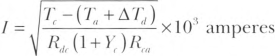 |
where:
| Tc | = | conductor temperature (°C) |
| Ta | = | ambient temperature (°C) |
| ΔTd | = | dielectric loss temperature rise |
| Rdc | = | dc resistance of conductor at temperature, Tc |
| Yc | = | component ac resistance resulting from skin effect and proximity effect |
| Rca | = | effective thermal resistance between conductor and surrounding ambient |
Informational Note: The dielectric loss temperature rise (ΔTd) is negligible for single circuit extruded dielectric cables rated below 46 kV.
(C) Tables.
Ampacities for conductors rated 2001 volts to 35,000 volts shall be as specified in Table 315.60(C)(1) through Table 315.60(C)(20). Ampacities for ambient temperatures other than those specified in the ampacity tables shall be corrected in accordance with 315.60(D)(4).
Informational Note No. 1: See IEEE 835, Standard Power Cable Ampacity Tables, and the references therein for availability of all factors and constants for ampacities calculated in accordance with 315.60(A).
Informational Note No. 2: See 210.19, Informational Note, for voltage drop on branch circuits that this section does not take into consideration. See 215.2(A)(2), Informational Note No. 2, for voltage drop on feeders that this section does not take into consideration.
Table 315.60(C)(1) Ampacities of Insulated Single Copper Conductor Cables Triplexed in Air.
| Conductor Size (AWG or kcmil) | Temperature Rating of Conductor | ||||
|---|---|---|---|---|---|
| 2001—5000 Volts Ampacity | 5001—35,000 Volts Ampacity | ||||
| 90°C (194°F) Type MV-90 | 105°C (221°F) Type MV-105 | 90°C (194°F) Type MV-90 | 105°C (221°F) Type MV-105 | ||
| 8 | 65 | 74 | - | - | |
| 6 | 90 | 99 | 100 | 110 | |
| 4 | 120 | 130 | 130 | 140 | |
| 2 | 160 | 175 | 170 | 195 | |
| 1 | 185 | 205 | 195 | 225 | |
| 1/0 | 215 | 240 | 225 | 255 | |
| 2/0 | 250 | 275 | 260 | 295 | |
| 3/0 | 290 | 320 | 300 | 340 | |
| 4/0 | 335 | 375 | 345 | 390 | |
| 250 | 375 | 415 | 380 | 430 | |
| 350 | 465 | 515 | 470 | 525 | |
| 500 | 580 | 645 | 580 | 650 | |
| 750 | 750 | 835 | 730 | 820 | |
| 1000 | 880 | 980 | 850 | 950 | |
Note: Refer to 315.60(E) for the basis of ampacities, 315.10(A) for conductor maximum operating temperature and application, and 315.60(D)(4) for the ampacity correction factors where the ambient air temperature is other than 40°C (104°F).
Table 315.60(C)(2) Ampacities of Insulated Single Aluminum Conductor Cables Triplexed in Air.
| Conductor Size (AWG or kcmil) | Temperature Rating of Conductor | ||||
|---|---|---|---|---|---|
| 2001—5000 Volts Ampacity | 5001—35,000 Volts Ampacity | ||||
| 90°C (194°F) Type MV-90 | 105°C (221°F) Type MV-105 | 90°C (194°F) Type MV-90 | 105°C (221°F) Type MV-105 | ||
| 8 | 50 | 57 | - | - | |
| 6 | 70 | 77 | 75 | 84 | |
| 4 | 90 | 100 | 100 | 110 | |
| 2 | 125 | 135 | 130 | 150 | |
| 1 | 145 | 160 | 150 | 175 | |
| 1/0 | 170 | 185 | 175 | 200 | |
| 2/0 | 195 | 215 | 200 | 230 | |
| 3/0 | 225 | 250 | 230 | 265 | |
| 4/0 | 265 | 290 | 270 | 305 | |
| 250 | 295 | 325 | 300 | 335 | |
| 350 | 365 | 405 | 370 | 415 | |
| 500 | 460 | 510 | 460 | 515 | |
| 750 | 600 | 665 | 590 | 660 | |
| 1000 | 715 | 800 | 700 | 780 | |
Note: Refer to 315.60(E) for basis of ampacities, 315.10(A) for conductor maximum operating temperature and application, and 315.60(D)(4) for the ampacity correction factors where the ambient air temperature is other than 40°C (104°F).
Table 315.60(C)(3) Ampacities of Insulated Single Copper Conductor Isolated in Air.
| Conductor Size (AWG or kcmil) | Temperature Rating of Conductor | |||||
|---|---|---|---|---|---|---|
| 2001—5000 Volts Ampacity | 5001—15,000 Volts Ampacity | 15,001—35,000 Volts Ampacity | ||||
| 90°C (194°F) Type MV-90 | 105°C (221°F) Type MV-105 | 90°C (194°F) Type MV-90 | 105°C (221°F) Type MV-105 | 90°C (194°F) Type MV-90 | 105°C (221°F) Type MV-105 | |
| 8 | 83 | 93 | - | - | - | - |
| 6 | 110 | 120 | 110 | 125 | - | - |
| 4 | 145 | 160 | 150 | 165 | - | - |
| 2 | 190 | 215 | 195 | 215 | - | - |
| 1 | 225 | 250 | 225 | 250 | 225 | 250 |
| 1/0 | 260 | 290 | 260 | 290 | 260 | 290 |
| 2/0 | 300 | 330 | 300 | 335 | 300 | 330 |
| 3/0 | 345 | 385 | 345 | 385 | 345 | 380 |
| 4/0 | 400 | 445 | 400 | 445 | 395 | 445 |
| 250 | 445 | 495 | 445 | 495 | 440 | 490 |
| 350 | 550 | 615 | 550 | 610 | 545 | 605 |
| 500 | 695 | 775 | 685 | 765 | 680 | 755 |
| 750 | 900 | 1000 | 885 | 990 | 870 | 970 |
| 1000 | 1075 | 1200 | 1060 | 1185 | 1040 | 1160 |
| 1250 | 1230 | 1370 | 1210 | 1350 | 1185 | 1320 |
| 1500 | 1365 | 1525 | 1345 | 1500 | 1315 | 1465 |
| 1750 | 1495 | 1665 | 1470 | 1640 | 1430 | 1595 |
| 2000 | 1605 | 1790 | 1575 | 1755 | 1535 | 1710 |
Note: Refer to 315.60(E) for the basis of ampacities, 315.10(A) for conductor maximum operating temperature and application, and 315.60(D)(4) for the ampacity correction factors where the ambient air temperature is other than 40°C (104°F).
Table 315.60(C)(4) Ampacities of Insulated Single Aluminum Conductor Isolated in Air.
| Conductor Size (AWG or kcmil) | Temperature Rating of Conductor | |||||
|---|---|---|---|---|---|---|
| 2001—5000 Volts Ampacity | 5001—15,000 Volts Ampacity | 15,001—35,000 Volts Ampacity | ||||
| 90°C (194°F) Type MV-90 | 105°C (221°F) Type MV-105 | 90°C (194°F) Type MV-90 | 105°C (221°F) Type MV-105 | 90°C (194°F) Type MV-90 | 105°C (221°F) Type MV-105 | |
| 8 | 64 | 71 | - | - | - | - |
| 6 | 85 | 95 | 87 | 97 | - | - |
| 4 | 115 | 125 | 115 | 130 | - | - |
| 2 | 150 | 165 | 150 | 170 | - | - |
| 1 | 175 | 195 | 175 | 195 | 175 | 195 |
| 1/0 | 200 | 225 | 200 | 225 | 200 | 225 |
| 2/0 | 230 | 260 | 235 | 260 | 230 | 260 |
| 3/0 | 270 | 300 | 270 | 300 | 270 | 300 |
| 4/0 | 310 | 350 | 310 | 350 | 310 | 345 |
| 250 | 345 | 385 | 345 | 385 | 345 | 380 |
| 350 | 430 | 480 | 430 | 480 | 430 | 475 |
| 500 | 545 | 605 | 535 | 600 | 530 | 590 |
| 750 | 710 | 790 | 700 | 780 | 685 | 765 |
| 1000 | 855 | 950 | 840 | 940 | 825 | 920 |
| 1250 | 980 | 1095 | 970 | 1080 | 950 | 1055 |
| 1500 | 1105 | 1230 | 1085 | 1215 | 1060 | 1180 |
| 1750 | 1215 | 1355 | 1195 | 1335 | 1165 | 1300 |
| 2000 | 1320 | 1475 | 1295 | 1445 | 1265 | 1410 |
Note: Refer to 315.60(E) for the basis of ampacities, 315.10(A) for conductor maximum operating temperature and application, and 315.60(D)(4) for the ampacity correction factors where the ambient air temperature is other than 40°C (104°F).
Table 315.60(C)(5) Ampacities of an Insulated Three-Conductor Copper Cable Isolated in Air.
| Conductor Size (AWG or kcmil) | Temperature Rating of Conductor | ||||
|---|---|---|---|---|---|
| 2001—5000 Volts Ampacity | 5001—35,000 Volts Ampacity | ||||
| 90°C (194°F) Type MV-90 | 105°C (221°F) Type MV-105 | 90°C (194°F) Type MV-90 | 105°C (221°F) Type MV-105 | ||
| 8 | 59 | 66 | - | - | |
| 6 | 79 | 88 | 93 | 105 | |
| 4 | 105 | 115 | 120 | 135 | |
| 2 | 140 | 154 | 165 | 185 | |
| 1 | 160 | 180 | 185 | 210 | |
| 1/0 | 185 | 205 | 215 | 240 | |
| 2/0 | 215 | 240 | 245 | 275 | |
| 3/0 | 250 | 280 | 285 | 315 | |
| 4/0 | 285 | 320 | 325 | 360 | |
| 250 | 320 | 355 | 360 | 400 | |
| 350 | 395 | 440 | 435 | 490 | |
| 500 | 485 | 545 | 535 | 600 | |
| 750 | 615 | 685 | 670 | 745 | |
| 1000 | 705 | 790 | 770 | 860 | |
Note: Refer to 315.60(E) for the basis of ampacities, 315.10(A) for conductor maximum operating temperature and application, and 315.60(D)(4) for the ampacity correction factors where the ambient air temperature is other than 40°C (104°F).
Table 315.60(C)(6) Ampacities of an Insulated Three-Conductor Aluminum Cable Isolated in Air.
| Conductor Size (AWG or kcmil) | Temperature Rating of Conductor | ||||
|---|---|---|---|---|---|
| 2001—5000 Volts Ampacity | 5001—35,000 Volts Ampacity | ||||
| 90°C (194°F) Type MV-90 | 105°C (221°F) Type MV-105 | 90°C (194°F) Type MV-90 | 105°C (221°F) Type MV-105 | ||
| 8 | 46 | 51 | - | - | |
| 6 | 61 | 68 | 72 | 80 | |
| 4 | 81 | 90 | 95 | 105 | |
| 2 | 110 | 120 | 125 | 145 | |
| 1 | 125 | 140 | 145 | 165 | |
| 1/0 | 145 | 160 | 170 | 185 | |
| 2/0 | 170 | 185 | 190 | 215 | |
| 3/0 | 195 | 215 | 220 | 245 | |
| 4/0 | 225 | 250 | 255 | 285 | |
| 250 | 250 | 280 | 280 | 315 | |
| 350 | 310 | 345 | 345 | 385 | |
| 500 | 385 | 430 | 425 | 475 | |
| 750 | 495 | 550 | 540 | 600 | |
| 1000 | 585 | 650 | 635 | 705 | |
Note: Refer to 315.60(E) for the basis of ampacities, 315.10(A) for conductor maximum operating temperature and application, and 315.60(D)(4) for the ampacity correction factors where the ambient air temperature is other than 40°C (104°F).
Table 315.60(C)(7) Ampacities of an Insulated Triplexed or Three Single-Conductor Copper Cables in Isolated Conduit in Air.
| Conductor Size (AWG or kcmil) | Temperature Rating of Conductor | ||||
|---|---|---|---|---|---|
| 2001—5000 Volts Ampacity | 5001—35,000 Volts Ampacity | ||||
| 90°C (194°F) Type MV-90 | 105°C (221°F) Type MV-105 | 90°C (194°F) Type MV-90 | 105°C (221°F) Type MV-105 | ||
| 8 | 55 | 61 | - | - | |
| 6 | 75 | 84 | 83 | 93 | |
| 4 | 97 | 110 | 110 | 120 | |
| 2 | 130 | 145 | 150 | 165 | |
| 1 | 155 | 175 | 170 | 190 | |
| 1/0 | 180 | 200 | 195 | 215 | |
| 2/0 | 205 | 225 | 225 | 255 | |
| 3/0 | 240 | 270 | 260 | 290 | |
| 4/0 | 280 | 305 | 295 | 330 | |
| 250 | 315 | 355 | 330 | 365 | |
| 350 | 385 | 430 | 395 | 440 | |
| 500 | 475 | 530 | 480 | 535 | |
| 750 | 600 | 665 | 585 | 655 | |
| 1000 | 690 | 770 | 675 | 755 | |
Note: Refer to 315.60(E) for the basis of ampacities, 315.10(A) for conductor maximum operating temperature and application, and 315.60(D)(4) for the ampacity correction factors where the ambient air temperature is other than 40°C (104°F).
Table 315.60(C)(8) Ampacities of an Insulated Triplexed or Three Single-Conductor Aluminum Cables in Isolated Conduit in Air.
| Conductor Size (AWG or kcmil) | Temperature Rating of Conductor | ||||
|---|---|---|---|---|---|
| 2001—5000 Volts Ampacity | 5001—35,000 Volts Ampacity | ||||
| 90°C (194°F) Type MV-90 | 105°C (221°F) Type MV-105 | 90°C (194°F) Type MV-90 | 105°C (221°F) Type MV-105 | ||
| 8 | 43 | 48 | - | - | |
| 6 | 58 | 65 | 65 | 72 | |
| 4 | 76 | 85 | 84 | 94 | |
| 2 | 100 | 115 | 115 | 130 | |
| 1 | 120 | 135 | 130 | 150 | |
| 1/0 | 140 | 155 | 150 | 170 | |
| 2/0 | 160 | 175 | 175 | 200 | |
| 3/0 | 190 | 210 | 200 | 225 | |
| 4/0 | 215 | 240 | 230 | 260 | |
| 250 | 250 | 280 | 255 | 290 | |
| 350 | 305 | 340 | 310 | 350 | |
| 500 | 380 | 425 | 385 | 430 | |
| 750 | 490 | 545 | 485 | 540 | |
| 1000 | 580 | 645 | 565 | 640 | |
Note: Refer to 315.60(E) for the basis of ampacities, 315.10(A) for conductor maximum operating temperature and application, and 315.60(D)(4) for the ampacity correction factors where the ambient air temperature is other than 40°C (104°F).
Table 315.60(C)(9) Ampacities of an Insulated Three-Conductor Copper Cable in Isolated Conduit in Air.
| Conductor Size (AWG or kcmil) | Temperature Rating of Conductor | ||||
|---|---|---|---|---|---|
| 2001—5000 Volts Ampacity | 5001—35,000 Volts Ampacity | ||||
| 90°C (194°F) Type MV-90 | 105°C (221°F) Type MV-105 | 90°C (194°F) Type MV-90 | 105°C (221°F) Type MV-105 | ||
| 8 | 52 | 58 | - | - | |
| 6 | 69 | 77 | 83 | 92 | |
| 4 | 91 | 100 | 105 | 120 | |
| 2 | 125 | 135 | 145 | 165 | |
| 1 | 140 | 155 | 165 | 185 | |
| 1/0 | 165 | 185 | 195 | 215 | |
| 2/0 | 190 | 210 | 220 | 245 | |
| 3/0 | 220 | 245 | 250 | 280 | |
| 4/0 | 255 | 285 | 290 | 320 | |
| 250 | 280 | 315 | 315 | 350 | |
| 350 | 350 | 390 | 385 | 430 | |
| 500 | 425 | 475 | 470 | 525 | |
| 750 | 525 | 585 | 570 | 635 | |
| 1000 | 590 | 660 | 650 | 725 | |
Note: Refer to 315.60(E) for the basis of ampacities, 315.10(A) for conductor maximum operating temperature and application, and 315.60(D)(4) for the ampacity correction factors where the ambient air temperature is other than 40°C (104°F).
Table 315.60(C)(10) Ampacities of an Insulated Three-Conductor Aluminum Cable in Isolated Conduit in Air.
| Conductor Size (AWG or kcmil) | Temperature Rating of Conductor | ||||
|---|---|---|---|---|---|
| 2001—5000 Volts Ampacity | 5001—35,000 Volts Ampacity | ||||
| 90°C (194°F) Type MV-90 | 105°C (221°F) Type MV-105 | 90°C (194°F) Type MV-90 | 105°C (221°F) Type MV-105 | ||
| 8 | 41 | 46 | - | - | |
| 6 | 53 | 59 | 64 | 71 | |
| 4 | 71 | 79 | 84 | 94 | |
| 2 | 96 | 105 | 115 | 125 | |
| 1 | 110 | 125 | 130 | 145 | |
| 1/0 | 130 | 145 | 150 | 170 | |
| 2/0 | 150 | 165 | 170 | 190 | |
| 3/0 | 170 | 190 | 195 | 220 | |
| 4/0 | 200 | 225 | 225 | 255 | |
| 250 | 220 | 245 | 250 | 280 | |
| 350 | 275 | 305 | 305 | 340 | |
| 500 | 340 | 380 | 380 | 425 | |
| 750 | 430 | 480 | 470 | 520 | |
| 1000 | 505 | 560 | 550 | 615 | |
Note: Refer to 315.60(E) for the basis of ampacities, 315.10(A) for conductor maximum operating temperature and application, and 315.60(D)(4) for the ampacity correction factors where the ambient air temperature is other than 40°C (104°F).
Table 315.60(C)(11) Ampacities of Three Single-Insulated Copper Conductors in Underground Electrical Ducts (Three Conductors per Electrical Duct).
| Conductor Size (AWG or kcmil) | Temperature Rating of Conductor | ||||
|---|---|---|---|---|---|
| 2001—5000 Volts Ampacity | 5001—35,000 Volts Ampacity | ||||
| 90°C (194°F) Type MV-90 | 105°C (221°F) Type MV-105 | 90°C (194°F) Type MV-90 | 105°C (221°F) Type MV-105 | ||
| One Circuit [See Figure 315.60(D)(3), Detail 1.] | |||||
| 8 | 64 | 69 | - | - | |
| 6 | 85 | 92 | 90 | 97 | |
| 4 | 110 | 120 | 115 | 125 | |
| 2 | 145 | 155 | 155 | 165 | |
| 1 | 170 | 180 | 175 | 185 | |
| 1/0 | 195 | 210 | 200 | 215 | |
| 2/0 | 220 | 235 | 230 | 245 | |
| 3/0 | 250 | 270 | 260 | 275 | |
| 4/0 | 290 | 310 | 295 | 315 | |
| 250 | 320 | 345 | 325 | 345 | |
| 350 | 385 | 415 | 390 | 415 | |
| 500 | 470 | 505 | 465 | 500 | |
| 750 | 585 | 630 | 565 | 610 | |
| 1000 | 670 | 720 | 640 | 690 | |
| Three Circuits [See Figure 315.60(D)(3), Detail 2.] | |||||
| 8 | 56 | 60 | - | - | |
| 6 | 73 | 79 | 77 | 83 | |
| 4 | 95 | 100 | 99 | 105 | |
| 2 | 125 | 130 | 130 | 135 | |
| 1 | 140 | 150 | 145 | 155 | |
| 1/0 | 160 | 175 | 165 | 175 | |
| 2/0 | 185 | 195 | 185 | 200 | |
| 3/0 | 210 | 225 | 210 | 225 | |
| 4/0 | 235 | 255 | 240 | 255 | |
| 250 | 260 | 280 | 260 | 280 | |
| 350 | 315 | 335 | 310 | 330 | |
| 500 | 375 | 405 | 370 | 395 | |
| 750 | 460 | 495 | 440 | 475 | |
| 1000 | 525 | 565 | 495 | 535 | |
| Six Circuits [See Figure 315.60(D)(3), Detail 3.] | |||||
| 8 | 48 | 52 | - | - | |
| 6 | 62 | 67 | 64 | 68 | |
| 4 | 80 | 86 | 82 | 88 | |
| 2 | 105 | 110 | 105 | 115 | |
| 1 | 115 | 125 | 120 | 125 | |
| 1/0 | 135 | 145 | 135 | 145 | |
| 2/0 | 150 | 160 | 150 | 165 | |
| 3/0 | 170 | 185 | 170 | 185 | |
| 4/0 | 195 | 210 | 190 | 205 | |
| 250 | 210 | 225 | 210 | 225 | |
| 350 | 250 | 270 | 245 | 265 | |
| 500 | 300 | 325 | 290 | 310 | |
| 750 | 365 | 395 | 350 | 375 | |
| 1000 | 410 | 445 | 390 | 415 | |
Note: Refer to 315.60(F) for basis of ampacities and Table 315.10(A) for the temperature rating of the conductor.
Table 315.60(C)(12) Ampacities of Three Single-Insulated Aluminum Conductors in Underground Electrical Ducts (Three Conductors per Electrical Duct).
| Conductor Size (AWG or kcmil) | Temperature Rating of Conductor | ||||
|---|---|---|---|---|---|
| 2001—5000 Volts Ampacity | 5001—35,000 Volts Ampacity | ||||
| 90°C (194°F) Type MV-90 | 105°C (221°F) Type MV-105 | 90°C (194°F) Type MV-90 | 105°C (221°F) Type MV-105 | ||
| One Circuit [See Figure 315.60(D)(3), Detail 1.] | |||||
| 8 | 50 | 54 | - | - | |
| 6 | 66 | 71 | 70 | 75 | |
| 4 | 86 | 93 | 91 | 98 | |
| 2 | 115 | 125 | 120 | 130 | |
| 1 | 130 | 140 | 135 | 145 | |
| 1/0 | 150 | 160 | 155 | 165 | |
| 2/0 | 170 | 185 | 175 | 190 | |
| 3/0 | 195 | 210 | 200 | 215 | |
| 4/0 | 225 | 245 | 230 | 245 | |
| 250 | 250 | 270 | 250 | 270 | |
| 350 | 305 | 325 | 305 | 330 | |
| 500 | 370 | 400 | 370 | 400 | |
| 750 | 470 | 505 | 455 | 490 | |
| 1000 | 545 | 590 | 525 | 565 | |
| Three Circuits [See Figure 315.60(D)(3), Detail 2.] | |||||
| 8 | 44 | 47 | - | - | |
| 6 | 57 | 61 | 60 | 65 | |
| 4 | 74 | 80 | 77 | 83 | |
| 2 | 96 | 105 | 100 | 105 | |
| 1 | 110 | 120 | 110 | 120 | |
| 1/0 | 125 | 135 | 125 | 140 | |
| 2/0 | 145 | 155 | 145 | 155 | |
| 3/0 | 160 | 175 | 165 | 175 | |
| 4/0 | 185 | 200 | 185 | 200 | |
| 250 | 205 | 220 | 200 | 220 | |
| 350 | 245 | 265 | 245 | 260 | |
| 500 | 295 | 320 | 290 | 315 | |
| 750 | 370 | 395 | 355 | 385 | |
| 1000 | 425 | 460 | 405 | 440 | |
| Six Circuits [See Figure 315.60(D)(3), Detail 3.] | |||||
| 8 | 38 | 41 | - | - | |
| 6 | 48 | 52 | 50 | 54 | |
| 4 | 62 | 67 | 64 | 69 | |
| 2 | 80 | 86 | 80 | 88 | |
| 1 | 91 | 98 | 90 | 99 | |
| 1/0 | 105 | 110 | 105 | 110 | |
| 2/0 | 115 | 125 | 115 | 125 | |
| 3/0 | 135 | 145 | 130 | 145 | |
| 4/0 | 150 | 165 | 150 | 160 | |
| 250 | 165 | 180 | 165 | 175 | |
| 350 | 195 | 210 | 195 | 210 | |
| 500 | 240 | 255 | 230 | 250 | |
| 750 | 290 | 315 | 280 | 305 | |
| 1000 | 335 | 360 | 320 | 345 | |
Note: Refer to 315.60(F) for basis of ampacities and Table 315.10(A) for the temperature rating of the conductor.
Table 315.60(C)(13) Ampacities of Three Insulated Copper Conductors Cabled Within an Overall Covering (Three-Conductor Cable) in Underground Electrical Ducts (One Cable per Electrical Duct).
| Conductor Size (AWG or kcmil) | Temperature Rating of Conductor | ||||
|---|---|---|---|---|---|
| 2001—5000 Volts Ampacity | 5001—35,000 Volts Ampacity | ||||
| 90°C (194°F) Type MV-90 | 105°C (221°F) Type MV-105 | 90°C (194°F) Type MV-90 | 105°C (221°F) Type MV-105 | ||
| One Circuit [See Figure 315.60(D)(3), Detail 1.] | |||||
| 8 | 59 | 64 | - | - | |
| 6 | 78 | 84 | 88 | 95 | |
| 4 | 100 | 110 | 115 | 125 | |
| 2 | 135 | 145 | 150 | 160 | |
| 1 | 155 | 165 | 170 | 185 | |
| 1/0 | 175 | 190 | 195 | 210 | |
| 2/0 | 200 | 220 | 220 | 235 | |
| 3/0 | 230 | 250 | 250 | 270 | |
| 4/0 | 265 | 285 | 285 | 305 | |
| 250 | 290 | 315 | 310 | 335 | |
| 350 | 355 | 380 | 375 | 400 | |
| 500 | 430 | 460 | 450 | 485 | |
| 750 | 530 | 570 | 545 | 585 | |
| 1000 | 600 | 645 | 615 | 660 | |
| Three Circuits [See Figure 315.60(D)(3), Detail 2.] | |||||
| 8 | 53 | 57 | - | - | |
| 6 | 69 | 74 | 75 | 81 | |
| 4 | 89 | 96 | 97 | 105 | |
| 2 | 115 | 125 | 125 | 135 | |
| 1 | 135 | 145 | 140 | 155 | |
| 1/0 | 150 | 165 | 160 | 175 | |
| 2/0 | 170 | 185 | 185 | 195 | |
| 3/0 | 195 | 210 | 205 | 220 | |
| 4/0 | 225 | 240 | 230 | 250 | |
| 250 | 245 | 265 | 255 | 270 | |
| 350 | 295 | 315 | 305 | 325 | |
| 500 | 355 | 380 | 360 | 385 | |
| 750 | 430 | 465 | 430 | 465 | |
| 1000 | 485 | 520 | 485 | 515 | |
| Six Circuits [See Figure 315.60(D)(3), Detail 3.] | |||||
| 8 | 46 | 50 | - | - | |
| 6 | 60 | 65 | 63 | 68 | |
| 4 | 77 | 83 | 81 | 87 | |
| 2 | 98 | 105 | 105 | 110 | |
| 1 | 110 | 120 | 115 | 125 | |
| 1/0 | 125 | 135 | 130 | 145 | |
| 2/0 | 145 | 155 | 150 | 160 | |
| 3/0 | 165 | 175 | 170 | 180 | |
| 4/0 | 185 | 200 | 190 | 200 | |
| 250 | 200 | 220 | 205 | 220 | |
| 350 | 240 | 270 | 245 | 275 | |
| 500 | 290 | 310 | 290 | 305 | |
| 750 | 350 | 375 | 340 | 365 | |
| 1000 | 390 | 420 | 380 | 405 | |
Note: Refer to 315.60(F) for basis of ampacities and Table 315.10(A) for the temperature rating of the conductor.
Table 315.60(C)(14) Ampacities of Three Insulated Aluminum Conductors Cabled Within an Overall Covering (Three-Conductor Cable) in Underground Electrical Ducts (One Cable per Electrical Duct).
| Conductor Size (AWG or kcmil) | Temperature Rating of Conductor | ||||
|---|---|---|---|---|---|
| 2001—5000 Volts Ampacity | 5001—35,000 Volts Ampacity | ||||
| 90°C (194°F) Type MV-90 | 105°C (221°F) Type MV-105 | 90°C (194°F) Type MV-90 | 105°C (221°F) Type MV-105 | ||
| One Circuit [See Figure 315.60(D)(3), Detail 1.] | |||||
| 8 | 46 | 50 | - | - | |
| 6 | 61 | 66 | 69 | 74 | |
| 4 | 80 | 86 | 89 | 96 | |
| 2 | 105 | 110 | 115 | 125 | |
| 1 | 120 | 130 | 135 | 145 | |
| 1/0 | 140 | 150 | 150 | 165 | |
| 2/0 | 160 | 170 | 170 | 185 | |
| 3/0 | 180 | 195 | 195 | 210 | |
| 4/0 | 205 | 220 | 220 | 240 | |
| 250 | 230 | 245 | 245 | 265 | |
| 350 | 280 | 310 | 295 | 315 | |
| 500 | 340 | 365 | 355 | 385 | |
| 750 | 425 | 460 | 440 | 475 | |
| 1000 | 495 | 535 | 510 | 545 | |
| Three Circuits [See Figure 315.60(D)(3), Detail 2.] | |||||
| 8 | 41 | 44 | - | - | |
| 6 | 54 | 58 | 59 | 64 | |
| 4 | 70 | 75 | 75 | 81 | |
| 2 | 90 | 97 | 100 | 105 | |
| 1 | 105 | 110 | 110 | 120 | |
| 1/0 | 120 | 125 | 125 | 135 | |
| 2/0 | 135 | 145 | 140 | 155 | |
| 3/0 | 155 | 165 | 160 | 175 | |
| 4/0 | 175 | 185 | 180 | 195 | |
| 250 | 190 | 205 | 200 | 215 | |
| 350 | 230 | 250 | 240 | 255 | |
| 500 | 280 | 300 | 285 | 305 | |
| 750 | 345 | 375 | 350 | 375 | |
| 1000 | 400 | 430 | 400 | 430 | |
| Six Circuits [See Figure 315.60(D)(3), Detail 3.] | |||||
| 8 | 36 | 39 | - | - | |
| 6 | 46 | 50 | 49 | 53 | |
| 4 | 60 | 65 | 63 | 68 | |
| 2 | 77 | 83 | 80 | 86 | |
| 1 | 87 | 94 | 90 | 98 | |
| 1/0 | 99 | 105 | 105 | 110 | |
| 2/0 | 110 | 120 | 115 | 125 | |
| 3/0 | 130 | 140 | 130 | 140 | |
| 4/0 | 145 | 155 | 150 | 160 | |
| 250 | 160 | 170 | 160 | 170 | |
| 350 | 190 | 205 | 190 | 205 | |
| 500 | 230 | 245 | 230 | 245 | |
| 750 | 280 | 305 | 275 | 295 | |
| 1000 | 320 | 345 | 315 | 335 | |
Note: Refer to 315.60(F) for basis of ampacities and Table 315.10(A) for the temperature rating of the conductor.
Table 315.60(C)(15) Ampacities of Single Insulated Copper Conductors Directly Buried in Earth.
| Conductor Size (AWG or kcmil) | Temperature Rating of Conductor | ||||
|---|---|---|---|---|---|
| 2001—5000 Volts Ampacity | 5001—35,000 Volts Ampacity | ||||
| 90°C (194°F) Type MV-90 | 105°C (221°F) Type MV-105 | 90°C (194°F) Type MV-90 | 105°C (221°F) Type MV-105 | ||
| One Circuit, Three Conductors [See Figure 315.60(D)(3), Detail 9.] | |||||
| 8 | 110 | 115 | - | - | |
| 6 | 140 | 150 | 130 | 140 | |
| 4 | 180 | 195 | 170 | 180 | |
| 2 | 230 | 250 | 210 | 225 | |
| 1 | 260 | 280 | 240 | 260 | |
| 1/0 | 295 | 320 | 275 | 295 | |
| 2/0 | 335 | 365 | 310 | 335 | |
| 3/0 | 385 | 415 | 355 | 380 | |
| 4/0 | 435 | 465 | 405 | 435 | |
| 250 | 470 | 510 | 440 | 475 | |
| 350 | 570 | 615 | 535 | 575 | |
| 500 | 690 | 745 | 650 | 700 | |
| 750 | 845 | 910 | 805 | 865 | |
| 1000 | 980 | 1055 | 930 | 1005 | |
| Two Circuits, Six Conductors [See Figure 315.60(D)(3), Detail 10.] | |||||
| 8 | 100 | 110 | - | - | |
| 6 | 130 | 140 | 120 | 130 | |
| 4 | 165 | 180 | 160 | 170 | |
| 2 | 215 | 230 | 195 | 210 | |
| 1 | 240 | 260 | 225 | 240 | |
| 1/0 | 275 | 295 | 255 | 275 | |
| 2/0 | 310 | 335 | 290 | 315 | |
| 3/0 | 355 | 380 | 330 | 355 | |
| 4/0 | 400 | 430 | 375 | 405 | |
| 250 | 435 | 470 | 410 | 440 | |
| 350 | 520 | 560 | 495 | 530 | |
| 500 | 630 | 680 | 600 | 645 | |
| 750 | 775 | 835 | 740 | 795 | |
| 1000 | 890 | 960 | 855 | 920 | |
Note: Refer to 315.60(F) for basis of ampacities and Table 315.10(A) for the temperature rating of the conductor.
Table 315.60(C)(16) Ampacities of Single Insulated Aluminum Conductors Directly Buried in Earth.
| Conductor Size (AWG or kcmil) | Temperature Rating of Conductor | ||||
|---|---|---|---|---|---|
| 2001—5000 Volts Ampacity | 5001—35,000 Volts Ampacity | ||||
| 90°C (194°F) Type MV-90 | 105°C (221°F) Type MV-105 | 90°C (194°F) Type MV-90 | 105°C (221°F) Type MV-105 | ||
| One Circuit, Three Conductors [See Figure 315.60(D)(3), Detail 9.] | |||||
| 8 | 85 | 90 | - | - | |
| 6 | 110 | 115 | 100 | 110 | |
| 4 | 140 | 150 | 130 | 140 | |
| 2 | 180 | 195 | 165 | 175 | |
| 1 | 205 | 220 | 185 | 200 | |
| 1/0 | 230 | 250 | 215 | 230 | |
| 2/0 | 265 | 285 | 245 | 260 | |
| 3/0 | 300 | 320 | 275 | 295 | |
| 4/0 | 340 | 365 | 315 | 340 | |
| 250 | 370 | 395 | 345 | 370 | |
| 350 | 445 | 480 | 415 | 450 | |
| 500 | 540 | 580 | 510 | 545 | |
| 750 | 665 | 720 | 635 | 680 | |
| 1000 | 780 | 840 | 740 | 795 | |
| Two Circuits, Six Conductors [See Figure 315.60(D)(3), Detail 10.] | |||||
| 8 | 80 | 85 | - | - | |
| 6 | 100 | 110 | 95 | 100 | |
| 4 | 130 | 140 | 125 | 130 | |
| 2 | 165 | 180 | 155 | 165 | |
| 1 | 190 | 200 | 175 | 190 | |
| 1/0 | 215 | 230 | 200 | 215 | |
| 2/0 | 245 | 260 | 225 | 245 | |
| 3/0 | 275 | 295 | 255 | 275 | |
| 4/0 | 310 | 335 | 290 | 315 | |
| 250 | 340 | 365 | 320 | 345 | |
| 350 | 410 | 440 | 385 | 415 | |
| 500 | 495 | 530 | 470 | 505 | |
| 750 | 610 | 655 | 580 | 625 | |
| 1000 | 710 | 765 | 680 | 730 | |
Note: Refer to 315.60(F) for basis of ampacities and Table 315.10(A) for the temperature rating of the conductor.
Table 315.60(C)(17) Ampacities of Three Insulated Copper Conductors Cabled Within an Overall Covering (Three-Conductor Cable), Directly Buried in Earth.
| Conductor Size (AWG or kcmil) | Temperature Rating of Conductor | ||||
|---|---|---|---|---|---|
| 2001—5000 Volts Ampacity | 5001—35,000 Volts Ampacity | ||||
| 90°C (194°F) Type MV-90 | 105°C (221°F) Type MV-105 | 90°C (194°F) Type MV-90 | 105°C (221°F) Type MV-105 | ||
| One Circuit [See Figure 315.60(D)(3), Detail 5.] | |||||
| 8 | 85 | 89 | - | - | |
| 6 | 105 | 115 | 115 | 120 | |
| 4 | 135 | 150 | 145 | 155 | |
| 2 | 180 | 190 | 185 | 200 | |
| 1 | 200 | 215 | 210 | 225 | |
| 1/0 | 230 | 245 | 240 | 255 | |
| 2/0 | 260 | 280 | 270 | 290 | |
| 3/0 | 295 | 320 | 305 | 330 | |
| 4/0 | 335 | 360 | 350 | 375 | |
| 250 | 365 | 395 | 380 | 410 | |
| 350 | 440 | 475 | 460 | 495 | |
| 500 | 530 | 570 | 550 | 590 | |
| 750 | 650 | 700 | 665 | 720 | |
| 1000 | 730 | 785 | 750 | 810 | |
| Two Circuits [See Figure 315.60(D)(3), Detail 6.] | |||||
| 8 | 80 | 84 | - | - | |
| 6 | 100 | 105 | 105 | 115 | |
| 4 | 130 | 140 | 135 | 145 | |
| 2 | 165 | 180 | 170 | 185 | |
| 1 | 185 | 200 | 195 | 210 | |
| 1/0 | 215 | 230 | 220 | 235 | |
| 2/0 | 240 | 260 | 250 | 270 | |
| 3/0 | 275 | 295 | 280 | 305 | |
| 4/0 | 310 | 335 | 320 | 345 | |
| 250 | 340 | 365 | 350 | 375 | |
| 350 | 410 | 440 | 420 | 450 | |
| 500 | 490 | 525 | 500 | 535 | |
| 750 | 595 | 640 | 605 | 650 | |
| 1000 | 665 | 715 | 675 | 730 | |
Note: Refer to 315.60(F) for basis of ampacities and Table 315.10(A) for the temperature rating of the conductor.
Table 315.60(C)(18) Ampacities of Three Insulated Aluminum Conductors Cabled Within an Overall Covering (Three-Conductor Cable), Directly Buried in Earth.
| Conductor Size (AWG or kcmil) | Temperature Rating of Conductor | ||||
|---|---|---|---|---|---|
| 2001—5000 Volts Ampacity | 5001—35,000 Volts Ampacity | ||||
| 90°C (194°F) Type MV-90 | 105°C (221°F) Type MV-105 | 90°C (194°F) Type MV-90 | 105°C (221°F) Type MV-105 | ||
| One Circuit [See Figure 315.60(D)(3), Detail 5.] | |||||
| 8 | 65 | 70 | - | - | |
| 6 | 80 | 88 | 90 | 95 | |
| 4 | 105 | 115 | 115 | 125 | |
| 2 | 140 | 150 | 145 | 155 | |
| 1 | 155 | 170 | 165 | 175 | |
| 1/0 | 180 | 190 | 185 | 200 | |
| 2/0 | 205 | 220 | 210 | 225 | |
| 3/0 | 230 | 250 | 240 | 260 | |
| 4/0 | 260 | 280 | 270 | 295 | |
| 250 | 285 | 310 | 300 | 320 | |
| 350 | 345 | 375 | 360 | 390 | |
| 500 | 420 | 450 | 435 | 470 | |
| 750 | 520 | 560 | 540 | 580 | |
| 1000 | 600 | 650 | 620 | 665 | |
| Two Circuits [See Figure 315.60(D)(3), Detail 6.] | |||||
| 8 | 60 | 66 | - | - | |
| 6 | 75 | 83 | 80 | 95 | |
| 4 | 100 | 110 | 105 | 115 | |
| 2 | 130 | 140 | 135 | 145 | |
| 1 | 145 | 155 | 150 | 165 | |
| 1/0 | 165 | 180 | 170 | 185 | |
| 2/0 | 190 | 205 | 195 | 210 | |
| 3/0 | 215 | 230 | 220 | 240 | |
| 4/0 | 245 | 260 | 250 | 270 | |
| 250 | 265 | 285 | 275 | 295 | |
| 350 | 320 | 345 | 330 | 355 | |
| 500 | 385 | 415 | 395 | 425 | |
| 750 | 480 | 515 | 485 | 525 | |
| 1000 | 550 | 590 | 560 | 600 | |
Note: Refer to 315.60(F) for basis of ampacities and Table 315.10(A) for the temperature rating of the conductor.
Table 315.60(C)(19) Ampacities of Three Triplexed Single Insulated Copper Conductors Directly Buried in Earth.
| Conductor Size (AWG or kcmil) | Temperature Rating of Conductor | ||||
|---|---|---|---|---|---|
| 2001—5000 Volts Ampacity | 5001—35,000 Volts Ampacity | ||||
| 90°C (194°F) Type MV-90 | 105°C (221°F) Type MV-105 | 90°C (194°F) Type MV-90 | 105°C (221°F) Type MV-105 | ||
| One Circuit, Three Conductors [See Figure 315.60(D)(3), Detail 7.] | |||||
| 8 | 90 | 95 | - | - | |
| 6 | 120 | 130 | 115 | 120 | |
| 4 | 150 | 165 | 150 | 160 | |
| 2 | 195 | 205 | 190 | 205 | |
| 1 | 225 | 240 | 215 | 230 | |
| 1/0 | 255 | 270 | 245 | 260 | |
| 2/0 | 290 | 310 | 275 | 295 | |
| 3/0 | 330 | 360 | 315 | 340 | |
| 4/0 | 375 | 405 | 360 | 385 | |
| 250 | 410 | 445 | 390 | 410 | |
| 350 | 490 | 580 | 470 | 505 | |
| 500 | 590 | 635 | 565 | 605 | |
| 750 | 725 | 780 | 685 | 740 | |
| 1000 | 825 | 885 | 770 | 830 | |
| Two Circuits, Six Conductors [See Figure 315.60(D)(3), Detail 8.] | |||||
| 8 | 85 | 90 | - | - | |
| 6 | 110 | 115 | 105 | 115 | |
| 4 | 140 | 150 | 140 | 150 | |
| 2 | 180 | 195 | 175 | 190 | |
| 1 | 205 | 220 | 200 | 215 | |
| 1/0 | 235 | 250 | 225 | 240 | |
| 2/0 | 265 | 285 | 255 | 275 | |
| 3/0 | 300 | 320 | 290 | 315 | |
| 4/0 | 340 | 365 | 325 | 350 | |
| 250 | 370 | 395 | 355 | 380 | |
| 350 | 445 | 480 | 425 | 455 | |
| 500 | 535 | 575 | 510 | 545 | |
| 750 | 650 | 700 | 615 | 660 | |
| 1000 | 740 | 795 | 690 | 745 | |
Note: Refer to 315.60(F) for basis of ampacities and Table 315.10(A) for the temperature rating of the conductor.
Table 315.60(C)(20) Ampacities of Three Triplexed Single Insulated Aluminum Conductors Directly Buried in Earth.
| Conductor Size (AWG or kcmil) | Temperature Rating of Conductor | ||||
|---|---|---|---|---|---|
| 2001—5000 Volts Ampacity | 5001—35,000 Volts Ampacity | ||||
| 90°C (194°F) Type MV-90 | 105°C (221°F) Type MV-105 | 90°C (194°F) Type MV-90 | 105°C (221°F) Type MV-105 | ||
| One Circuit, Three Conductors [See Figure 315.60(D)(3), Detail 7.] | |||||
| 8 | 70 | 75 | - | - | |
| 6 | 90 | 100 | 90 | 95 | |
| 4 | 120 | 130 | 115 | 125 | |
| 2 | 155 | 165 | 145 | 155 | |
| 1 | 175 | 190 | 165 | 175 | |
| 1/0 | 200 | 210 | 190 | 205 | |
| 2/0 | 225 | 240 | 215 | 230 | |
| 3/0 | 255 | 275 | 245 | 265 | |
| 4/0 | 290 | 310 | 280 | 305 | |
| 250 | 320 | 350 | 305 | 325 | |
| 350 | 385 | 420 | 370 | 400 | |
| 500 | 465 | 500 | 445 | 480 | |
| 750 | 580 | 625 | 550 | 590 | |
| 1000 | 670 | 725 | 635 | 680 | |
| Two Circuits, Six Conductors [See Figure 315.60(D)(3), Detail 8.] | |||||
| 8 | 65 | 70 | - | - | |
| 6 | 85 | 95 | 85 | 90 | |
| 4 | 110 | 120 | 105 | 115 | |
| 2 | 140 | 150 | 135 | 145 | |
| 1 | 160 | 170 | 155 | 170 | |
| 1/0 | 180 | 195 | 175 | 190 | |
| 2/0 | 205 | 220 | 200 | 215 | |
| 3/0 | 235 | 250 | 225 | 245 | |
| 4/0 | 265 | 285 | 255 | 275 | |
| 250 | 290 | 310 | 280 | 300 | |
| 350 | 350 | 375 | 335 | 360 | |
| 500 | 420 | 455 | 405 | 435 | |
| 750 | 520 | 560 | 485 | 525 | |
| 1000 | 600 | 645 | 565 | 605 | |
Note: Refer to 315.60(F) for basis of ampacities and Table 315.10(A) for the temperature rating of the conductor.
(D) Ampacity Adjustment.
(1) Grounded Shields.
Ampacities shown in Table 315.60(C)(3), Table 315.60(C)(4), Table 315.60(C)(15), and Table 315.60(C)(16) shall apply for cables with shields grounded at one point only. Where shields for these cables are grounded at more than one point, ampacities shall be adjusted to take into consideration the heating due to shield currents.
Informational Note: Tables other than those listed contain the ampacity of cables with shields grounded at multiple points.
(2) Burial Depth.
Where the burial depth of direct burial or electrical duct bank circuits is modified from the values shown in a figure or table, ampacities shall be permitted to be modified as indicated in 315.60(D)(2)(a) and (D)(2)(b). No ampacity adjustments shall be required where the burial depth is decreased.
- Where burial depths are increased in part(s) of an electrical duct run, a decrease in ampacity of the conductors shall not be required, provided the total length of parts of the duct run increased in depth is less than 25 percent of the total run length.
- Where burial depths are deeper than shown in a specific underground ampacity table or figure, an ampacity derating factor of 6 percent per 300 mm (1 ft) increase in depth for all values of rho shall be permitted.
(3) Electrical Ducts Entering Equipment Enclosures.
At locations where electrical ducts enter equipment enclosures from underground, spacing between such ducts, as shown in Figure 315.60(D)(3), shall be permitted to be reduced without requiring the ampacity of conductors therein to be reduced. 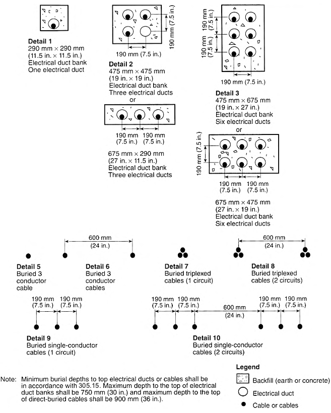
(4) Ambient Temperature Correction.
Ampacities for ambient temperatures other than those specified in the ampacity tables shall be corrected in accordance with Table 315.60(D)(4) or shall be permitted to be calculated using the following equation:
| [315.60(D)(4)] |
 |
where:
| I' | = | ampacity corrected for ambient temperature |
| I | = | ampacity shown in the table for Tc and Ta |
| Tc | = | temperature rating of conductor (°C) |
| Ta' | = | new ambient temperature (°C) |
| Ta | = | ambient temperature used in the table (°C) |
Informational Note: See 110.40 for ambient temperature adjustments for terminals.
Table 315.60(D)(4) Ambient Temperature Correction Factors.
| For ambient temperatures other than 40°C (104°F), multiply the allowable ampacities specified in the ampacity tables by the appropriate factor shown below. | |||
|---|---|---|---|
| Ambient Temperature (°C) | Temperature Rating of Conductor | Ambient Temperature (°F) | |
| 90°C | 105°C | ||
| 10 or less | 1.26 | 1.21 | 50 or less |
| 11—15 | 1.22 | 1.18 | 51—59 |
| 16—20 | 1.18 | 1.14 | 60—68 |
| 21—25 | 1.14 | 1.11 | 69—77 |
| 26—30 | 1.10 | 1.07 | 78—86 |
| 31—35 | 1.05 | 1.04 | 87—95 |
| 36—40 | 1.00 | 1.00 | 96—104 |
| 41—45 | 0.95 | 0.96 | 105—113 |
| 46—50 | 0.89 | 0.92 | 114—122 |
| 51—55 | 0.84 | 0.88 | 123—131 |
| 56—60 | 0.77 | 0.83 | 132—140 |
| 61—65 | 0.71 | 0.78 | 141—149 |
| 66—70 | 0.63 | 0.73 | 150—158 |
| 71—75 | 0.55 | 0.68 | 159—167 |
| 76—80 | 0.45 | 0.62 | 168—176 |
| 81—85 | 0.32 | 0.55 | 177—185 |
| 86—90 | - | 0.48 | 186—194 |
| 91—95 | - | 0.39 | 195—203 |
| 96—100 | - | 0.28 | 204—212 |
(E) Ampacity in Air.
Ampacities for conductors and cables in air shall be as specified in Table 315.60(C)(1) through Table 315.60(C)(10). Ampacities shall be based on the following:
- Conductor temperatures of 90°C (194°F) and 105°C (221°F)
- Ambient air temperature of 40°C (104°F)
Informational Note: See 315.60(D)(4) where the ambient air temperature is other than 40°C (104°F).
(F) Ampacity in Underground Electrical Ducts and Direct Buried in Earth.
Ampacities for conductors and cables in underground electrical ducts and direct buried in earth shall be as specified in Table 315.60(C)(11) through Table 315.60(C)(20). Ampacities shall be based on the following:
- Ambient earth temperature of 20°C (68°F)
- Arrangement in accordance with Figure 315.60(D)(3)
- 100 percent load factor
- Thermal resistance (Rho) of 90
- Conductor temperatures 90°C (194°F) and 105°C (221°F)
- Minimum burial depths to the top electrical ducts or cables shall be in accordance with 305.15.
- Maximum depth to the top of electrical duct banks shall be 750 mm (30 in.), and maximum depth to the top of direct-buried cables shall be 900 mm (36 in.).
Article 320
Armored Cable: Type AC
320.1 Scope.
This article covers the use, installation, and construction specifications for armored cable, Type AC.
320.10 Uses Permitted.
Type AC cable shall be permitted as follows:
- For feeders and branch circuits in both exposed and concealed installations
- In cable trays
- In dry locations
- Embedded in plaster finish on brick or other masonry, except in damp or wet locations
- To be run or fished in the air voids of masonry block or tile walls where such walls are not exposed or subject to excessive moisture or dampness
Informational Note: The "Uses Permitted" is not an all-inclusive list.
320.12 Uses Not Permitted.
Type AC cable shall not be used as follows:
- Where subject to physical damage
- In damp or wet locations
- In air voids of masonry block or tile walls where such walls are exposed or subject to excessive moisture or dampness
- Where exposed to corrosive conditions
- Embedded in plaster finish on brick or other masonry in damp or wet locations
320.23 In Accessible Attics.
Type AC cables in accessible attics or roof spaces shall be installed as specified in 320.23(A) and (B).
(A) Cables Run Across the Top of Framing Members.
Where run across the top of framing members, or across the face of rafters or studding within 2.1 m (7 ft) of the floor or horizontal surface, the cable shall be protected by guard strips that are at least as high as the cable. Where this space is not accessible by permanently installed stairs or ladders, protection shall only be required within 1.8 m (6 ft) of the nearest edge of the scuttle hole or attic entrance.
320.30 Securing and Supporting.
(A) General.
(C) Supporting.
Unless otherwise permitted, Type AC cable shall be supported at intervals not exceeding 1.4 m (41/2 ft).
Horizontal runs of Type AC cable installed in wooden or metal framing members or similar supporting means shall be considered supported and secured where such support does not exceed 1.4 m (41/2 ft) intervals.
(D) Unsupported Cables.
Type AC cable shall be permitted to be unsupported and unsecured where the cable complies with any of the following:
- Is fished between access points through concealed spaces in finished buildings or structures and supporting is impracticable
- Is not more than 600 mm (2 ft) in length at terminals where flexibility is necessary
- Is not more than 1.8 m (6 ft) in length from the last point of cable support to the point of connection to a luminaire(s) or other electrical equipment and the cable and point of connection are within an accessible ceiling
320.40 Boxes and Fittings.
At all points where the armor of AC cable terminates, a fitting shall be provided to protect wires from abrasion, unless the design of the outlet boxes or fittings is such as to afford equivalent protection, and, in addition, an insulating bushing or its equivalent protection shall be provided between the conductors and the armor. The connector or clamp by which the Type AC cable is fastened to boxes or cabinets shall be of such design that the insulating bushing or its equivalent will be visible for inspection. Where change is made from Type AC cable to other cable or raceway wiring methods, a box, fitting, or conduit body shall be installed at junction points as required in 300.15.
320.80 Ampacity.
(A) Thermal Insulation.
Armored cable installed in thermal insulation shall have conductors rated at 90°C (194°F). The ampacity of cable installed in these applications shall not exceed that of a 60°C (140°F) rated conductor. The 90°C (194°F) rating shall be permitted to be used for ampacity adjustment and correction calculations; however, the ampacity shall not exceed that of a 60°C (140°F) rated conductor.
Where more than two Type AC cables containing two or more current-carrying conductors in each cable are installed in contact with thermal insulation, caulk, or sealing foam without maintaining spacing between cables, the ampacity of each conductor shall be adjusted in accordance with Table 310.15(C)(1).
320.100 Construction.
Type AC cable shall have an armor of flexible metal tape and shall have an internal bonding strip of copper or aluminum in intimate contact with the armor for its entire length.
320.104 Conductors.
Insulated conductors shall be of a type listed in Table 310.4(1) or those identified for use in this cable. In addition, the conductors shall have an overall moisture-resistant and fire-retardant fibrous covering. For Type ACT, a moisture-resistant fibrous covering shall be required only on the individual conductors.
320.108 Equipment Grounding Conductor.
Type AC cable shall provide an adequate path for fault current as required by 250.4(A)(5) or (B)(4) to act as an equipment grounding conductor.
Article 322
Flat Cable Assemblies: Type FC
322.1 Scope.
This article covers the use, installation, and construction specifications for flat cable assemblies, Type FC.
322.10 Uses Permitted.
Flat cable assemblies shall be permitted only as follows:
- As branch circuits to supply suitable tap devices for lighting, small appliances, or small power loads. The rating of the branch circuit shall not exceed 30 amperes.
- Where installed for exposed work.
- In locations where they will not be subjected to physical damage. Where a flat cable assembly is installed less than 2.5 m (8 ft) above the floor or fixed working platform, it shall be protected by a cover identified for the use.
- In surface metal raceways identified for the use. The channel portion of the surface metal raceway systems shall be installed as complete systems before the flat cable assemblies are pulled into the raceways.
322.12 Uses Not Permitted.
Flat cable assemblies shall not be used as follows:
- Where exposed to corrosive conditions, unless suitable for the application
- In hoistways or on elevators or escalators
- In any hazardous (classified) location, except as specifically permitted by other articles in this Code.
- Outdoors or in wet or damp locations unless identified for the use
322.40 Boxes and Fittings.
(A) Dead Ends.
322.56 Splices and Taps.
(A) Splices.
Splices shall be made in listed junction boxes.
(B) Taps.
Taps shall be made between any phase conductor and the grounded conductor or any other phase conductor by means of devices and fittings identified for the use. Tap devices shall be rated at not less than 15 amperes, or more than 300 volts to ground, and shall be marked in accordance with 322.120(C).
322.112 Insulation.
The entire flat cable assembly shall be formed to provide a suitable insulation covering all the conductors and using one of the materials recognized in Table 310.4(1) for general branch-circuit wiring.
322.120 Marking.
(B) Identification of Grounded Conductor.
The grounded conductor shall be identified throughout its length by means of a distinctive and durable white or gray marking.
Informational Note: The color gray may have been used in the past as an ungrounded conductor. Care should be taken when working on existing systems.
(C) Terminal Block Identification.
Terminal blocks identified for the use shall have distinctive and durable markings for color or word coding. The grounded conductor section shall have a white marking or other suitable designation. The next adjacent section of the terminal block shall have a black marking or other suitable designation. The next section shall have a red marking or other suitable designation. The final or outer section, opposite the grounded conductor section of the terminal block, shall have a blue marking or other suitable designation.
Article 324
Flat Conductor Cable: Type FCC
324.1 Scope.
This article covers a field-installed wiring system for branch circuits incorporating Type FCC cable and associated accessories as defined by the article. The wiring system is designed for installation under carpet squares.
324.10 Uses Permitted.
(A) Branch Circuits.
Use of FCC systems shall be permitted both for general-purpose and appliance branch circuits and for individual branch circuits.
(B) Branch-Circuit Ratings.
(1) Voltage.
Voltage between ungrounded conductors shall not exceed 300 volts. Voltage between ungrounded conductors and the grounded conductor shall not exceed 150 volts.
(2) Current.
General-purpose and appliance branch circuits shall have ratings not exceeding 20 amperes. Individual branch circuits shall have ratings not exceeding 30 amperes.
(C) Floors.
Use of FCC systems shall be permitted on hard, sound, smooth, continuous floor surfaces made of concrete, ceramic, or composition flooring, wood, and similar materials.
(E) Damp Locations.
Use of FCC systems in damp locations shall be permitted.
(F) Heated Floors.
Materials used for floors heated in excess of 30°C (86°F) shall be identified as suitable for use at these temperatures.
(G) System Height.
Any portion of an FCC system with a height above floor level exceeding 2.3 mm (0.090 in.) shall be tapered or feathered at the edges to floor level.
324.18 Crossings.
Crossings of more than two Type FCC cable runs shall not be permitted at any one point. Crossings of a Type FCC cable over or under a flat communications or signal cable shall be permitted. In each case, a grounded layer of metal shielding shall separate the two cables, and crossings of more than two flat cables shall not be permitted at any one point.
324.30 Securing and Supporting.
All FCC system components shall be firmly anchored to the floor or wall using an adhesive or mechanical anchoring system identified for this use. Floors shall be prepared to ensure adherence of the FCC system to the floor until the carpet squares are placed.
324.40 Boxes and Fittings.
(A) Cable Connections and Insulating Ends.
All Type FCC cable connections shall use connectors identified for their use, installed such that electrical continuity, insulation, and sealing against dampness and liquid spillage are provided. All bare cable ends shall be insulated and sealed against dampness and liquid spillage using listed insulating ends.
(B) Polarization of Connections.
All receptacles and connections shall be constructed and installed so as to maintain proper polarization of the system.
(C) Shields.
(1) Top Shield.
A metal top shield shall be installed over all floor-mounted Type FCC cable, connectors, and insulating ends. The top shield shall completely cover all cable runs, corners, connectors, and ends.
(D) Connection to Other Systems.
Power feed, grounding connection, and shield system connection between the FCC system and other wiring systems shall be accomplished in a transition assembly identified for this use.
(E) Metal-Shield Connectors.
Metal shields shall be connected to each other and to boxes, receptacle housings, self-contained devices, and transition assemblies using metal-shield connectors.
324.41 Floor Coverings.
Floor-mounted Type FCC cable, cable connectors, and insulating ends shall be covered with carpet squares not larger than 1.0 m (39.37 in.) square. Carpet squares that are adhered to the floor shall be attached with release-type adhesives.
324.42 Devices.
(A) Receptacles.
All receptacles, receptacle housings, and self-contained devices used with the FCC system shall be identified for this use and shall be connected to the Type FCC cable and metal shields. Connection from any equipment grounding conductor of the Type FCC cable shall be made to the shield system at each receptacle.
(B) Receptacles and Housings.
Receptacle housings and self-contained devices designed either for floor mounting or for in-wall or on-wall mounting shall be permitted for use with the FCC system. Receptacle housings and self-contained devices shall incorporate means for facilitating entry and termination of Type FCC cable and for electrically connecting the housing or device with the metal shield. Receptacles and self-contained devices shall comply with 406.4. Power and communications outlets installed together in common housing shall be permitted in accordance with 800.133(A)(3), Exception No. 2.
324.56 Splices and Taps.
(A) FCC Systems Alterations.
Alterations to FCC systems shall be permitted. New cable connectors shall be used at new connection points to make alterations. It shall be permitted to leave unused cable runs and associated cable connectors in place and energized. All cable ends shall be covered with insulating ends.
(B) Transition Assemblies.
All transition assemblies shall be identified for their use. Each assembly shall incorporate means for facilitating entry of the Type FCC cable into the assembly, for connecting the Type FCC cable to grounded conductors, and for electrically connecting the assembly to the metal cable shields and to equipment grounding conductors.
324.60 Grounding and Bonding.
All metal shields, boxes, receptacle housings, and self-contained devices shall be electrically continuous to the equipment grounding conductor of the supplying branch circuit. All such electrical connections shall be made with connectors identified for this use. The electrical resistivity of such shield system shall not be more than that of one conductor of the Type FCC cable used in the installation.
324.100 Construction.
(A) Type FCC Cable.
Type FCC cable shall be listed for use with the FCC system and shall consist of three, four, or five flat copper conductors, one of which shall be an equipment grounding conductor.
(B) Shields.
(1) Materials and Dimensions.
All top and bottom shields shall be of designs and materials identified for their use. Top shields shall be metal. Both metallic and nonmetallic materials shall be permitted for bottom shields.
(2) Resistivity.
Metal shields shall have cross-sectional areas that provide for electrical resistivity of not more than that of one conductor of the Type FCC cable used in the installation.
324.101 Corrosion Resistance.
Metal components of the system shall be either corrosion resistant, coated with corrosion-resistant materials, or insulated from contact with corrosive substances.
324.112 Insulation.
The insulating material of the cable shall be moisture resistant and flame retardant. All insulating materials in the FCC systems shall be identified for their use.
324.120 Markings.
(B) Conductor Identification.
Conductors shall be clearly and durably identified on both sides throughout their length as specified in 310.6.
Article 326
Integrated Gas Spacer Cable: Type IGS
326.1 Scope.
This article covers the use, installation, and construction specifications for integrated gas spacer cable, Type IGS.
326.10 Uses Permitted.
Type IGS cable shall be permitted for use underground, including direct burial in the earth, as the following:
326.24 Bending Radius.
Where the coilable nonmetallic conduit and cable are bent for installation purposes or are flexed or bent during shipment or installation, the radius of the curve of the inner edge measured to the inside of the bend shall not be less than specified in Table 326.24.
Table 326.24 Minimum Radii of Bends.
| Conduit Size | Minimum Radii | ||
|---|---|---|---|
| Metric Designator | Trade Size | mm | in. |
| 53 | 2 | 600 | 24 |
| 78 | 3 | 900 | 35 |
| 103 | 4 | 1150 | 45 |
326.26 Bends.
A run of Type IGS cable between pull boxes or terminations shall not contain more than the equivalent of four quarter bends (360 degrees total), including those bends located immediately at the pull box or terminations.
326.40 Fittings.
Terminations and splices for Type IGS cable shall be identified as a type that is suitable for maintaining the gas pressure within the conduit. A valve and cap shall be provided for each length of the cable and conduit to check the gas pressure or to inject gas into the conduit.
326.80 Ampacity.
Table 326.80 Ampacity of Type IGS Cable.
| Size (kcmil) | Amperes | Size (kcmil) | Amperes |
|---|---|---|---|
| 250 | 119 | 2500 | 376 |
| 500 | 168 | 3000 | 412 |
| 750 | 206 | 3250 | 429 |
| 1000 | 238 | 3500 | 445 |
| 1250 | 266 | 3750 | 461 |
| 1500 | 292 | 4000 | 476 |
| 1750 | 315 | 4250 | 491 |
| 2000 | 336 | 4500 | 505 |
| 2250 | 357 | 4750 | 519 |
326.104 Conductors.
The conductors shall be solid aluminum rods, laid parallel, consisting of one to nineteen 12.7 mm (1/2 in.) diameter rods. The minimum conductor size shall be 250 kcmil, and the maximum size shall be 4750 kcmil.
326.112 Insulation.
The insulation shall be dry kraft paper tapes and a pressurized sulfur hexafluoride gas (SF6), both approved for electrical use. The nominal gas pressure shall be 138 kPa gauge (20 lb/in.2 gauge). The thickness of the paper spacer shall be as specified in Table 326.112.
Table 326.112 Paper Spacer Thickness.
| Size (kcmil) | Thickness | |
|---|---|---|
| mm | in. | |
| 250—1000 | 1.02 | 0.040 |
| 1250—4750 | 1.52 | 0.060 |
326.116 Conduit.
The conduit shall be a medium density polyethylene identified as suitable for use with natural gas rated pipe in metric designator 53, 78, or 103 (trade size 2, 3, or 4). The percent fill dimensions for the conduit are shown in Table 326.116.
Table 326.116 Conduit Dimensions.
| Conduit Size | Actual Outside Diameter | Actual Inside Diameter | |||
|---|---|---|---|---|---|
| Metric Designator | Trade Size | mm | in. | mm | in. |
| 53 | 2 | 60 | 2.375 | 49.46 | 1.947 |
| 78 | 3 | 89 | 3.500 | 73.30 | 2.886 |
| 103 | 4 | 114 | 4.500 | 94.23 | 3.710 |
Article 330
Metal-Clad Cable: Type MC
330.1 Scope.
This article covers the use, installation, and construction specifications of metal-clad cable, Type MC.
330.6 Listing Requirements.
Type MC cable shall be listed. Fittings used for connecting Type MC cable to boxes, cabinets, or other equipment shall be listed and identified for such use.
330.10 Uses Permitted.
(A) General Uses.
Type MC cable shall be permitted as follows:
- For services, feeders, and branch circuits.
- For power, lighting, control, and signal circuits.
- Indoors or outdoors.
- Exposed or concealed.
- To be direct buried where identified for such use.
- In cable tray where identified for such use.
- In any raceway.
- As aerial cable on a messenger.
- In hazardous (classified) locations where specifically permitted by other articles in this Code.
- In dry locations and embedded in plaster finish on brick or other masonry except in damp or wet locations.
- In damp or wet locations where a corrosion-resistant jacket is provided over the metallic covering and any of the following conditions are met:
- The metallic covering is impervious to moisture.
- A jacket resistant to moisture is provided under the metal covering.
- The insulated conductors under the metallic covering are listed for use in wet locations.
- Where single-conductor cables are used, all phase conductors and, where used, the grounded conductor shall be grouped together to minimize induced voltage on the sheath.
(B) Specific Uses.
Type MC cable shall be permitted to be installed in compliance with Parts II and III of Article 725 and 770.133 as applicable and in accordance with 330.10(B)(1) through (B)(4).
Informational Note: The "Uses Permitted" is not an all-inclusive list.
330.12 Uses Not Permitted.
Type MC cable shall not be used under either of the following conditions:
- Where subject to physical damage
- Where exposed to any of the destructive corrosive conditions in (a) or (b), unless the metallic sheath or armor is resistant to the conditions or is protected by material resistant to the conditions:
- Direct buried in the earth or embedded in concrete unless identified for direct burial
- Exposed to cinder fills, strong chlorides, caustic alkalis, or vapors of chlorine or of hydrochloric acids
330.24 Bending Radius.
Bends in Type MC cable shall be so made that the cable will not be damaged. The radius of the curve of the inner edge of any bend shall not be less than required in 330.24(A) through (C).
(A) Smooth Sheath.
- Ten times the external diameter of the metallic sheath for cable not more than 19 mm (3/4 in.) in external diameter
- Twelve times the external diameter of the metallic sheath for cable more than 19 mm (3/4 in.) but not more than 38 mm (11/2 in.) in external diameter
- Fifteen times the external diameter of the metallic sheath for cable more than 38 mm (11/2 in.) in external diameter
(B) Interlocked-Type Armor or Corrugated Sheath.
Seven times the external diameter of the metallic sheath.
(C) Shielded Conductors.
Twelve times the overall diameter of one of the individual conductors or seven times the overall diameter of the multiconductor cable, whichever is greater.
330.30 Securing and Supporting.
(A) General.
(B) Securing.
Unless otherwise permitted in this Code, cables shall be secured at intervals not exceeding 1.8 m (6 ft). Cables containing four or fewer conductors sized no larger than 10 AWG shall be secured within 300 mm (12 in.) of every box, cabinet, fitting, or other cable termination. In vertical installations, listed cables with ungrounded conductors 250 kcmil and larger shall be permitted to be secured at intervals not exceeding 3 m (10 ft).
(C) Supporting.
Unless otherwise permitted in this Code, cables shall be supported at intervals not exceeding 1.8 m (6 ft).
Horizontal runs of Type MC cable installed in wooden or metal framing members or similar supporting means shall be considered supported and secured where such support does not exceed 1.8 m (6 ft) intervals.
(D) Unsupported Cables.
Type MC cable shall be permitted to be unsupported and unsecured where the cable complies with any of the following:
- Is fished between access points through concealed spaces in finished buildings or structures and supporting is impractical
- Is not more than 1.8 m (6 ft) in length from the last point of cable support to the point of connection to luminaires or other electrical equipment and the cable and point of connection are within an accessible ceiling
- Is Type MC of the interlocked armor type in lengths not exceeding 900 mm (3 ft) from the last point where it is securely fastened and is used to connect equipment where flexibility is necessary to minimize the transmission of vibration from equipment or to provide flexibility for equipment that requires movement after installation
330.31 Single Conductors.
Where single-conductor cables with a nonferrous armor or sheath are used, the installation shall comply with 300.20.
330.80 Ampacity.
The ampacity of Type MC cable shall be determined in accordance with 310.14 or 315.60 for 14 AWG and larger conductors and in accordance with Table 402.5 for 18 AWG and 16 AWG conductors. The installation shall not exceed the temperature ratings of terminations and equipment.
(A) Type MC Cable Installed in Cable Tray.
The ampacities for Type MC cable installed in cable tray shall be determined in accordance with 392.80.
(B) Single Type MC Conductors Grouped Together.
Where single Type MC conductors are grouped together in a triangular or square configuration and installed on a messenger or exposed with a maintained free airspace of not less than 2.15 times one conductor diameter (2.15 × O.D.) of the largest conductor contained within the configuration and adjacent conductor configurations or cables, the ampacity of the conductors shall not exceed the allowable ampacities in the following tables:
- Table 310.20 for conductors rated 0 volts through 2000 volts
- Table 315.60(C)(1) and Table 315.60(C)(2) for conductors rated over 2000 volts
(C) Thermal Insulation.
Where more than two Type MC cables containing two or more current-carrying conductors in each cable are installed in contact with thermal insulation, caulk, or sealing foam without maintaining spacing between cables, the ampacity of each conductor shall be adjusted in accordance with Table 310.15(C)(1).
330.104 Conductors.
For ungrounded, grounded, and equipment grounding conductors, the minimum conductor sizes shall be 14 AWG copper, nickel, or nickel-coated copper and 12 AWG aluminum or copper-clad aluminum.
330.108 Equipment Grounding Conductor.
Where Type MC cable is used to provide an equipment grounding conductor, it shall comply with 250.118(A)(10) and 250.122.
330.112 Insulation.
(A) 1000 Volts or Less.
Insulated control and signal conductors in sizes 18 AWG and 16 AWG shall be of a type listed in Table 402.3, with a maximum operating temperature not less than 90°C (194°F) and as permitted by 724.49. Ungrounded, grounded, and equipment grounding conductors 16 AWG and larger shall be of a type listed in Table 310.4(1) or of a type identified for use in Type MC cable.
330.116 Sheath.
Metallic covering shall be one of the following types: smooth metallic sheath, corrugated metallic sheath, or interlocking metal tape armor. The metallic sheath shall be continuous and close fitting. A nonmagnetic sheath or armor shall be used on single conductor Type MC. Supplemental protection of an outer covering of corrosion-resistant material shall be permitted and shall be required where such protection is needed. The sheath shall not be used as a current-carrying conductor.
Informational Note: See 300.6 for protection against corrosion.
330.130 Hazardous (Classified) Locations.
Where required to be marked MC-HL, the cable shall be listed and shall have a gas/vapor tight continuous corrugated metallic sheath, an overall jacket of suitable polymeric material, and a separate equipment grounding conductor.
Article 332
Mineral-Insulated, Metal-Sheathed Cable: Type MI
332.1 Scope.
This article covers the use, installation, and construction specifications for mineral-insulated, metal-sheathed cable, Type MI.
332.10 Uses Permitted.
Type MI cable shall be permitted as follows:
- For services, feeders, and branch circuits
- For power, lighting, control, and signal circuits
- In dry, wet, or continuously moist locations
- Indoors or outdoors
- Where exposed or concealed
- Where embedded in plaster, concrete, fill, or other masonry, whether above or below grade
- In hazardous (classified) locations where specifically permitted by other articles in this Code
- Where exposed to oil and gasoline
- Where exposed to corrosive conditions not deteriorating to its sheath
- In underground runs where suitably protected against physical damage and corrosive conditions
- In or attached to cable tray
Informational Note: The "Uses Permitted" is not an all-inclusive list.
332.12 Uses Not Permitted.
Type MI cable shall not be used under the following conditions or in the following locations:
- In underground runs unless protected from physical damage, where necessary
- Where exposed to conditions that are destructive and corrosive to the metallic sheath, unless additional protection is provided
332.24 Bending Radius.
332.30 Securing and Supporting.
Type MI cable shall be supported and secured by staples, straps, hangers, or similar fittings, designed and installed so as not to damage the cable, at intervals not exceeding 1.8 m (6 ft).
(A) Horizontal Runs Through Holes and Notches.
In other than vertical runs, cables installed in accordance with 300.4 shall be considered supported and secured where such support does not exceed 1.8 m (6 ft) intervals.
332.31 Single Conductors.
Where single-conductor cables are used, all phase conductors and, where used, the neutral conductor shall be grouped together to minimize induced voltage on the sheath.
332.40 Boxes and Fittings.
(A) Fittings.
Fittings used for connecting Type MI cable to boxes, cabinets, or other equipment shall be identified for such use.
332.80 Ampacity.
The ampacity of Type MI cable shall be determined in accordance with 310.14. The conductor temperature at the end seal fitting shall not exceed the temperature rating of the listed end seal fitting, and the installation shall not exceed the temperature ratings of terminations or equipment.
(A) Type MI Cable Installed in Cable Tray.
The ampacities for Type MI cable installed in cable tray shall be determined in accordance with 392.80(A).
(B) Single Type MI Conductors Grouped Together.
Where single Type MI conductors are grouped together in a triangular or square configuration, as required by 332.31, and installed on a messenger or exposed with a maintained free air space of not less than 2.15 times one conductor diameter (2.15 × O.D.) of the largest conductor contained within the configuration and adjacent conductor configurations or cables, the ampacity of the conductors shall not exceed the allowable ampacities of Table 310.17.
332.104 Conductors.
Type Ml cable conductors shall be of solid copper, nickel, or nickel-coated copper with a resistance corresponding to standard AWG and kcmil sizes.
332.108 Equipment Grounding Conductor.
Where the outer sheath is made of copper, it shall provide an adequate path to serve as an equipment grounding conductor. Where the outer sheath is made of steel, a separate equipment grounding conductor shall be provided.
332.116 Sheath.
The outer sheath shall be of a continuous construction to provide mechanical protection and moisture seal.
Article 334
Nonmetallic-Sheathed Cable: Types NM and NMC
334.1 Scope.
This article covers the use, installation, and construction specifications of nonmetallic-sheathed cable.
334.10 Uses Permitted.
Type NM and Type NMC cables shall be permitted to be used in the following, except as prohibited in 334.12:
- One- and two-family dwellings and their attached or detached garages, and their storage buildings.
- Multi-family dwellings and their detached garages permitted to be of Types III, IV, and V construction.
- Other structures permitted to be of Types III, IV, and V construction. Cables shall be concealed within walls, floors, or ceilings that provide a thermal barrier of material that has at least a 15-minute finish rating as identified in listings of fire-rated assemblies.Informational Note No. 1: See NFPA 220-2021, Standard on Types of Building Construction, or the applicable building code, or both for types of building construction and occupancy classification definitions.Informational Note No. 2: See Informative Annex E for determination of building types.
- Cable trays in structures permitted to be Types III, IV, or V where the cables are identified for the use.Informational Note No. 3: See 310.14(A)(3) for temperature limitation of conductors.
- Types I and II construction where installed within raceways permitted to be installed in Types I and II construction.
(B) Type NMC.
Type NMC cable shall be permitted as follows:
- For both exposed and concealed work in dry, wet, damp, or corrosive locations, except as prohibited by 334.10(3)
- In outside and inside walls of masonry block or tile
- In a shallow chase in masonry, concrete, or adobe protected against nails or screws by a steel plate at least 1.59 mm (1/16 in.) thick and covered with plaster, adobe, or similar finish
334.12 Uses Not Permitted.
(A) Types NM and NMC.
Types NM and NMC cables shall not be permitted as follows:
- In any dwelling or structure not specifically permitted in 334.10(1), (2), (3), and (5)
- Exposed within a dropped or suspended ceiling cavity in other than one- and two-family and multifamily dwellings
- As service-entrance cable
- In commercial garages having hazardous (classified) locations as defined in 511.3
- In theaters and similar locations, except where permitted in 518.4(C)
- In motion picture studios
- In storage battery rooms
- In hoistways or on elevators or escalators
- Embedded in poured cement, concrete, or aggregate
- In hazardous (classified) locations, except where specifically permitted by other articles in this Code
(B) Type NM.
Type NM cables shall not be used under the following conditions or in the following locations:
- Where exposed to corrosive fumes or vapors
- Where embedded in masonry, concrete, adobe, fill, or plaster
- In a shallow chase in masonry, concrete, or adobe and covered with plaster, adobe, or similar finish
- In wet or damp locations
334.15 Exposed Work.
In exposed work, except as provided in 300.11(B), cable shall be installed as specified in 334.15(A) through (C).
(A) To Follow Surface.
Cable shall closely follow the surface of the building finish or of running boards.
(B) Protection From Physical Damage.
Cable shall be protected from physical damage where necessary by rigid metal conduit, intermediate metal conduit, electrical metallic tubing, Schedule 80 PVC conduit, RTRC marked with the suffix -XW, or other approved means. Where passing through a floor, the cable shall be enclosed in rigid metal conduit, intermediate metal conduit, electrical metallic tubing, Schedule 80 PVC conduit, RTRC marked with the suffix -XW, or other approved means extending at least 150 mm (6 in.) above the floor. Conduit or tubing shall be provided with a bushing or adapter that provides protection from abrasion at the point the cable enters and exits the raceway.
(C) In Unfinished Basements and Crawl Spaces.
Where cable is run at angles with joists in unfinished basements and crawl spaces, it shall be permissible to secure cables not smaller than two 6 AWG or three 8 AWG conductors directly to the lower edges of the joists. Smaller cables shall be run either through bored holes in joists or on running boards. Nonmetallic-sheathed cable installed on the wall of an unfinished basement shall be permitted to be installed in a listed conduit or tubing or shall be protected in accordance with 300.4. Conduit or tubing shall be provided with a bushing or adapter that provides protection from abrasion at the point the cable enters and exits the raceway. The sheath of the nonmetallic-sheathed cable shall extend through the conduit or tubing and into the outlet, device, or junction box not less than 6 mm (1/4 in.). The cable shall be secured within 300 mm (12 in.) of the point where the cable enters the conduit or tubing. Metal conduit, tubing, and metal outlet boxes shall be connected to an equipment grounding conductor complying with 250.86 and 250.148.
334.17 Through or Parallel to Framing Members.
Types NM and NMC cable shall be protected in accordance with 300.4 where installed through or parallel to framing members. Grommets used as required in 300.4(B)(1) shall remain in place and be listed for the purpose of cable protection.
334.19 Cable Entries.
The sheath on nonmetallic-sheathed cable shall extend not less than 6 mm (1/4 in.) beyond any cable clamp or cable entry.
334.24 Bending Radius.
Bends in Types NM and NMC cable shall be so made that the cable will not be damaged. The radius of the curve of the inner edge of any bend during or after installation shall not be less than five times the diameter of the cable. For flat cables, the major diameter dimension of the cable shall be used to determine the bending radius.
334.30 Securing and Supporting.
Nonmetallic-sheathed cable shall be supported and secured by staples, cable ties listed and identified for securement and support, or straps, hangers, or similar fittings designed and installed so as not to damage the cable, at intervals not exceeding 1.4 m (41/2 ft) and within 300 mm (12 in.) of every cable entry into enclosures such as outlet boxes, junction boxes, cabinets, or fittings. The cable length between the cable entry and the closest cable support shall not exceed 450 mm (18 in.). Flat cables shall not be stapled on edge.
(A) Horizontal Runs Through Holes and Notches.
In other than vertical runs, cables installed in accordance with 300.4 shall be considered to be supported and secured where such support does not exceed 1.4-m (41/2-ft) intervals and the nonmetallic-sheathed cable is securely fastened in place by an approved means within 300 mm (12 in.) of each box, cabinet, conduit body, or other nonmetallic-sheathed cable termination.
Informational Note: See 314.17(B)(1) for support where nonmetallic boxes are used.
(B) Unsupported Cables.
Nonmetallic-sheathed cable shall be permitted to be unsupported where the cable:
- Is fished between access points through concealed spaces in finished buildings or structures and supporting is impracticable.
- Is not more than 1.4 m (41/2 ft) from the last point of cable support to the point of connection to a luminaire or other piece of electrical equipment and the cable and point of connection are within an accessible ceiling in one-, two-, or multifamily dwellings.
(C) Wiring Device Without a Separate Outlet Box.
A wiring device identified for the use, without a separate outlet box, and incorporating an integral cable clamp shall be permitted where the cable is secured in place at intervals not exceeding 1.4 m (41/2 ft) and within 300 mm (12 in.) from the wiring device wall opening, and there shall be at least a 300 mm (12 in.) loop of unbroken cable or 150 mm (6 in.) of a cable end available on the interior side of the finished wall to permit replacement.
334.40 Boxes and Fittings.
(B) Devices of Insulating Material.
Self-contained switches, self-contained receptacles, and listed nonmetallic-sheathed cable interconnector devices of insulating material that are listed for use without a box shall be permitted to be used without boxes in exposed or concealed installations. Openings in such devices shall form a close fit around the outer covering of the cable, and the device shall fully enclose the part of the cable from which any part of the covering has been removed. Where connections to conductors are by binding-screw terminals, there shall be available as many terminals as conductors.
(C) Devices With Integral Enclosures.
Wiring devices with integral enclosures identified for such use shall be permitted as provided by 300.15(E).
334.80 Ampacity.
The ampacity of Types NM and NMC cable shall be determined in accordance with 310.14. The ampacity shall not exceed that of a 60°C (140°F) rated conductor. The 90°C (194°F) rating shall be permitted to be used for ampacity adjustment and correction calculations, provided the final calculated ampacity does not exceed that of a 60°C (140°F) rated conductor. The ampacity of Types NM and NMC cable installed in cable trays shall be determined in accordance with 392.80(A).
Where more than two NM cables containing two or more current-carrying conductors are installed, without maintaining spacing between the cables, through the same opening in wood framing that is to be sealed with thermal insulation, caulk, or sealing foam, the ampacity of each conductor shall be adjusted in accordance with Table 310.15(C)(1) and 310.14(A)(2), Exception, shall not apply.
Where more than two NM cables containing two or more current-carrying conductors are installed in contact with thermal insulation without maintaining spacing between cables, the ampacity of each conductor shall be adjusted in accordance with Table 310.15(C)(1) and 310.14(A)(2), Exception shall not apply.
334.104 Conductors.
The 600-volt insulated power conductors shall be sizes 14 AWG through 2 AWG copper conductors or sizes 12 AWG through 2 AWG aluminum or copper-clad aluminum conductors. Control and signaling conductors shall be no smaller than 18 AWG copper.
334.108 Equipment Grounding Conductor.
In addition to the insulated conductors, the cable shall have an insulated, covered, or bare equipment grounding conductor.
334.112 Insulation.
The insulated power conductors shall be one of the types listed in Table 310.4(1) that are suitable for branch-circuit wiring or one that is identified for use in these cables. Conductor insulation shall be rated at 90°C (194°F).
Informational Note: Types NM and NMC cable identified by the markings NM-B and NMC-B meet this requirement.
334.116 Sheath.
(A) Type NM.
The overall covering shall be flame retardant and moisture resistant.
(B) Type NMC.
The overall covering shall be flame retardant, moisture resistant, fungus resistant, and corrosion resistant.
Article 335
Instrumentation Tray Cable: Type ITC
335.1 Scope.
This article covers the use, installation, and construction specifications of instrumentation tray cable (Type ITC) for application to instrumentation and control circuits operating at 150 volts or less and 5 amperes or less.
335.3 Other Articles.
In addition to the provisions of this article, installation of Type ITC cable shall comply with other applicable articles of this Code.
335.4 Uses Permitted.
Type ITC cable shall be permitted to be used as follows in industrial establishments where the conditions of maintenance and supervision ensure that only qualified persons service the installation:
- In cable trays.
- In raceways.
- In hazardous locations as permitted in 501.10, 502.10, 503.10, 504.20, 504.30, 504.80, and 505.15.
- Enclosed in a smooth metallic sheath, continuous corrugated metallic sheath, or interlocking tape armor applied over the nonmetallic sheath in accordance with 335.6. The cable shall be supported and secured at intervals not exceeding 1.8 m (6 ft).
- Cable, without a metallic sheath or armor, that complies with the crush and impact requirements of Type MC cable and is identified for such use with the marking ITC-ER shall be permitted to be installed exposed. The cable shall be continuously supported and protected against physical damage using mechanical protection such as dedicated struts, angles, or channels. The cable shall be secured at intervals not exceeding 1.8 m (6 ft).Exception to (5): Where not subject to physical damage, Type ITC-ER shall be permitted to transition between cable trays and between cable trays and utilization equipment or devices for a distance not to exceed 1.8 m (6 ft) without continuous support. The cable shall be mechanically supported where exiting the cable tray to ensure that the minimum bending radius is not exceeded.
- As aerial cable on a messenger.
- Direct buried where identified for the use.
- Under raised floors in rooms containing industrial process control equipment and rack rooms where arranged to prevent damage to the cable.
- Under raised floors in information technology equipment rooms in accordance with 645.5(E)(2).
335.5 Uses Not Permitted.
Type ITC cable shall not be installed on circuits operating at more than 150 volts or more than 5 amperes.
Installation of Type ITC cable with other cables shall be subject to the stated requirements of the specific articles for the other cables. Where the governing articles do not contain stated requirements for installation with Type ITC cable, the installation of Type ITC cable with the other cables shall not be permitted.
Type ITC cable shall not be installed with power, lighting, Class 1 circuits that are not power limited, or non-power-limited circuits.
Exception No. 1: Where terminated within equipment or junction boxes and separations are maintained by insulating barriers or other means.
Exception No. 2: Where a metallic sheath or armor is applied over the nonmetallic sheath of the Type ITC cable.
335.6 Construction.
The insulated conductors of Type ITC cable shall be in sizes 22 AWG through 12 AWG. The conductor material shall be copper or thermocouple alloy. Insulation on the conductors shall be rated for 300 volts. Shielding shall be permitted.
The cable shall be listed as being resistant to the spread of fire. The outer jacket shall be sunlight and moisture resistant.
Where a smooth metallic sheath, continuous corrugated metallic sheath, or interlocking tape armor is applied over the nonmetallic sheath, an overall nonmetallic jacket shall not be required.
Informational Note: One method of defining resistant to the spread of fire is that the cables do not spread fire to the top of the tray in the UL flame exposure, vertical tray flame test in ANSI/UL 1685-2010, Vertical-Tray Fire-Propagation and Smoke-Release Test for Electrical and Optical-Fiber Cables. The smoke measurements in the test method are not applicable.
335.8 Ampacity.
The ampacity of the conductors shall be 5 amperes, except for 22 AWG conductors, which shall have an ampacity of 3 amperes.
335.9 Overcurrent Protection.
Overcurrent protection shall not exceed 5 amperes for 20 AWG and larger conductors, and 3 amperes for 22 AWG conductors.
Article 336
Power and Control Tray Cable: Type TC
336.10 Uses Permitted.
Type TC cable shall be permitted to be used as follows:
- For power, lighting, control, and signal circuits.
- In cable trays, including those with mechanically discontinuous segments up to 300 mm (1 ft).
- In raceways.
- In outdoor locations supported by a messenger wire.
- For Class 1 circuits as permitted in Parts II and III of Article 725.
- For non-power-limited fire alarm circuits if conductors comply with the requirements of 760.49.
- Between a cable tray and the utilization equipment or device(s), provided all of the following apply:
- The cable is Type TC-ER.
- The cable is installed in industrial establishments where the conditions of maintenance and supervision ensure that only qualified persons service the installation.
- The cable is continuously supported and protected against physical damage using mechanical protection such as struts, angles, or channels.
- The cable complies with the crush and impact requirements of Type MC cable and is identified with the marking "TC-ER."
- The cable is secured at intervals not exceeding 1.8 m (6 ft).
- Equipment grounding for the utilization equipment is provided by an equipment grounding conductor within the cable. In cables containing conductors sized 6 AWG or smaller, the equipment grounding conductor shall be provided within the cable or, at the time of installation, one or more insulated conductors shall be permanently identified as an equipment grounding conductor in accordance with 250.119(C).Exception to (7): Where not subject to physical damage, Type TC-ER shall be permitted to transition between cable trays and between cable trays and equipment or devices for a distance not to exceed 1.8 m (6 ft) without continuous support. The cable shall be mechanically supported where exiting the cable tray to ensure that the minimum bending radius is not exceeded.
- Type TC cable shall be resistant to moisture and corrosive agents where installed in wet locations.
- For one- and two-family dwelling units, Type TC-ER-JP cable containing conductors for both power and control circuits shall be permitted for branch circuits and feeders. Type TC-ER-JP cable used as interior wiring shall be installed per the requirements of Part II of Article 334 and where installed as exterior wiring shall be installed per the requirements of Part II of Article 340.
- Direct buried, where identified for such use.
- In hazardous (classified) locations where specifically permitted by other articles in this Code.
- For service-entrance conductors where identified for such use and marked Type TC-ER.
Informational Note No. 2: See 310.14(A)(3) for temperature limitation of conductors.
336.12 Uses Not Permitted.
336.24 Bending Radius.
Bends in Type TC cable shall be made so as not to damage the cable. For Type TC cable without metal shielding, the minimum bending radius shall be as follows:
- Four times the overall diameter for cables 25 mm (1 in.) or less in diameter
- Five times the overall diameter for cables larger than 25 mm (1 in.) but not more than 50 mm (2 in.) in diameter
- Six times the overall diameter for cables larger than 50 mm (2 in.) in diameter
Type TC cables with metallic shielding shall have a minimum bending radius of not less than 12 times the cable overall diameter.
336.100 Construction.
A metallic sheath or armor as defined in 330.116 shall not be permitted either under or over the nonmetallic jacket. Metallic shield(s) shall be permitted over groups of conductors, under the outer jacket, or both.
336.104 Conductors.
For ungrounded, grounded, and equipment grounding conductors, the conductor sizes shall be 14 AWG through 1000 kcmil copper, nickel, or nickel-coated copper and 12 AWG through 1000 kcmil aluminum or copper-clad aluminum. Insulation types shall be one of the types listed in Table 310.4(1) or Table 310.4(2) that is suitable for branch circuit and feeder circuits or one that is identified for such use.
(B) Thermocouple Circuits.
Conductors in Type TC cable used for thermocouple circuits in accordance with Part III of Article 724 shall also be permitted to be any of the materials used for thermocouple extension wire.
336.116 Jacket.
The outer jacket shall be a flame-retardant, nonmetallic material.
336.130 Hazardous (Classified) Location Cable.
Cable listed and marked Type TC-ER-HL shall comply with the following:
- The overall nonmetallic jacket shall be suitable for the environment.
- The overall cable construction shall be essentially circular in cross-section.
- The overall nonmetallic jacket shall be continuous and gas/vapor tight.
- For construction greater than 25.4 mm (1 in.) in diameter, the following shall apply:
- The equipment grounding conductor shall be bare.
- A metallic shield shall be included over all conductors under the outer jacket.
Article 337
Type P Cable
337.1 Scope.
This article covers the use, installation, and construction specifications for up through 2000 volt Type P cable (armored and unarmored).
337.10 Uses Permitted.
Type P cable shall be permitted to be used:
337.12 Uses Not Permitted.
Type P cable shall not be installed or used:
- Where it will be exposed to physical damage
- Where not specifically permitted by other articles in the Code
337.24 Bending Radius.
The minimum bending radii during installations and handling in service shall be adequate to prevent damage to the cable.
337.30 Securing and Supporting.
Type P cable shall be supported and secured by cable ties listed and identified for securement and support; straps, hangers, or similar fittings; or other approved means designed and installed so as not to damage the cable.
337.80 Ampacity.
The ampacity of Type P cable shall be determined in accordance with 310.14(A) or (B) for 14 AWG and larger conductors. For 18 AWG and 16 AWG conductors, the ampacities shall be determined in accordance with Table 402.5 or 310.14(B). When installed in cable tray, the ampacities shall be permitted to be determined in accordance with 392.80. The installation shall not exceed the temperature ratings of terminations and equipment.
337.104 Conductors.
Conductors shall be of tinned copper. Conductors shall employ flexible stranding. The minimum conductor size shall be 18 AWG.
337.108 Equipment Grounding Conductor.
An equipment grounding conductor complying with 250.122 shall be provided within multiconductor Type P cable.
337.112 Insulation.
Insulated conductors shall be a thermoset type identified for use in Type P cable. All conductors shall be suitable for wet locations. The minimum wall thickness shall be 0.76 mm (30 mils).
337.115 Jacket.
Multiconductor cables shall have an overall nonmetallic jacket that is impervious to moisture, corrosion resistant, and sunlight resistant. When installed external to an enclosure or industrial machinery, single conductor cables shall have an overall nonmetallic jacket that is impervious to moisture, corrosion resistant, and sunlight resistant. Single conductor cables rated 2000 volts with conductor sizes equal to or larger than 4/0 AWG shall be permitted to use an increased insulation thickness in lieu of using a separate cable jacket. When the increased insulation thickness is used, the insulation material shall be sunlight resistant.
337.116 Armor.
Armor shall be permitted over the jacket. If provided, the armor or metallic covering shall be a braided basket weave type consisting of wire laid closely together, flat and parallel, and forming a basket weave that shall firmly grip the cable. The wire shall be commercial bronze, tinned copper, stainless steel, or aluminum. The armor shall not be used as a current-carrying conductor or as an equipment grounding conductor. A nonmetallic jacket that conforms to 337.115 shall be provided over the armor.
337.120 Marking.
Type P cable shall be marked in accordance with 310.8. When an armor is provided, the cable shall be marked accordingly.
Article 338
Service-Entrance Cable: Types SE and USE
338.10 Uses Permitted.
(A) Service-Entrance Conductors.
Service-entrance cable shall be permitted to be used as service-entrance conductors and shall be installed in accordance with 230.6, 230.7, and Parts II, III, and IV of Article 230.
(B) Branch Circuits or Feeders.
(2) Use of Uninsulated Conductor.
Type SE service-entrance cable shall be permitted for use where the insulated conductors are used for circuit wiring and the uninsulated conductor is used only for equipment grounding purposes.
Exception: In existing installations, uninsulated conductors shall be permitted as a grounded conductor in accordance with 250.32 and 250.140, where the uninsulated grounded conductor of the cable originates in service equipment, and with 225.30 through 225.40.
(3) Temperature Limitations.
Type SE service-entrance cable used to supply appliances shall not be subject to conductor temperatures in excess of the temperature specified for the type of insulation involved.
(4) Installation Methods for Branch Circuits and Feeders.
- Interior Installations. Interior installations shall comply with the following:
- In addition to the provisions of this article, Type SE service-entrance cable used for interior wiring shall comply with the installation requirements of Part II of Article 334, excluding 334.80.
- Where more than two Type SE cables containing two or more current-carrying conductors in each cable are installed in contact with thermal insulation, caulk, or sealing foam without maintaining spacing between cables, the ampacity of each conductor shall be adjusted in accordance with Table 310.15(C)(1).
- For Type SE cable with ungrounded conductor sizes 10 AWG and smaller, where installed in contact with thermal insulation, the ampacity shall be in accordance with 60°C (140°F) conductor temperature rating. The maximum conductor temperature rating shall be permitted to be used for ampacity adjustment and correction purposes, if the final ampacity does not exceed that for a 60°C (140°F) rated conductor.
- Exterior Installations. Exterior installations shall comply with the following:
- In addition to the provisions of this article, service-entrance cable used for feeders or branch circuits, where installed as exterior wiring, shall be installed in accordance with Part I of Article 225. The cable shall be supported in accordance with 334.30.
- Type USE cable installed as underground feeder and branch circuit cable shall comply with Part II of Article 340.
Exception: Single-conductor Type USE and multi-rated USE conductors shall not be subject to the ampacity limitations of Part II of Article 340.
338.12 Uses Not Permitted.
(A) Service-Entrance Cable.
Type SE cable shall not be used under the following conditions or in the following locations:
- Where subject to physical damage unless protected in accordance with 230.50(B)
- Underground with or without a raceway
- For exterior branch circuits and feeder wiring unless the installation complies with Part I of Article 225 and is supported in accordance with 334.30 or is used as messenger-supported wiring as permitted in Part II of Article 396
(B) Underground Service-Entrance Cable.
Type USE cable shall not be used under the following conditions or in the following locations:
- For interior wiring
- For aboveground installations except where USE cable emerges from the ground and is terminated in an enclosure at an outdoor location and the cable is protected in accordance with 300.5(D)
- As aerial cable unless it is a multiconductor cable identified for use aboveground and installed as messenger-supported wiring in accordance with 225.10 and Part II of Article 396
338.24 Bending Radius.
Bends in Types USE and SE cable shall be so made that the cable will not be damaged. The radius of the curve of the inner edge of any bend, during or after installation, shall not be less than five times the diameter of the cable. For flat cables, the major diameter dimension of the cable shall be used to determine the bending radius.
338.100 Construction.
(A) Assemblies.
Cabled assemblies of multiple single-conductor Type USE conductors shall be permitted for direct burial. All conductors shall be insulated.
Informational Note: The term "cabled" refers to a manufacturing process of twisting single conductors together and may also be referred to as "plexed."
(B) Uninsulated Conductor.
Type SE or USE cable with an overall covering containing two or more conductors shall be permitted to have one conductor uninsulated.
338.120 Marking.
Service-entrance cable shall be marked as required in 310.8. Cable with the neutral conductor smaller than the ungrounded conductors shall be so marked.
Article 340
Underground Feeder and Branch-Circuit Cable: Type UF
340.10 Uses Permitted.
Type UF cable shall be permitted as follows:
- For use underground, including direct burial in the earth.
- As single-conductor cables. Where installed as single-conductor cables, all conductors of the feeder or branch circuit, including the grounded conductor and equipment grounding conductor, if any, shall be installed in accordance with 300.3.
- For wiring in wet, dry, or corrosive locations.
- Installed as nonmetallic-sheathed cable. Where so installed, the installation and conductor requirements shall comply with Parts II and III of Article 334, except for 334.12(B), and shall be of the multiconductor type.
- As single-conductor cables as the nonheating leads for heating cables as provided in 424.43.
- Supported by cable trays. Type UF cable supported by cable trays shall be of the multiconductor type.
Informational Note: See 310.14(A)(3) for temperature limitation of conductors.
340.12 Uses Not Permitted.
Type UF cable shall not be used as follows:
- As service-entrance cable
- In commercial garages
- In theaters and similar locations
- In motion picture studios
- In storage battery rooms
- In hoistways or on elevators or escalators
- In hazardous (classified) locations, except as specifically permitted by other articles in this Code
- Embedded in poured cement, concrete, or aggregate, except where embedded in plaster as nonheating leads where permitted in 424.43
- Where exposed to direct rays of the sun, unless identified as sunlight resistantInformational Note: The sunlight-resistant marking on the jacket does not apply to the individual conductors.
- Where subject to physical damage
- As overhead cable, except where installed as messenger-supported wiring in accordance with Part II of Article 396
340.104 Conductors.
The conductors shall be sizes 14 AWG copper or 12 AWG aluminum or copper-clad aluminum through 4/0 AWG.
340.108 Equipment Grounding Conductor.
In addition to the insulated conductors, the cable shall be permitted to have an insulated or bare equipment grounding conductor.
340.112 Insulation.
The conductors of Type UF shall be one of the moisture-resistant types listed in Table 310.4(1) that is suitable for branch-circuit wiring or one that is identified for such use. Where installed as a substitute wiring method for NM cable, the conductor insulation shall be rated 90°C (194°F).
340.116 Sheath.
The overall covering shall be flame retardant; moisture, fungus, and corrosion resistant; and suitable for direct burial in the earth.
Article 342
Intermediate Metal Conduit (IMC)
342.10 Uses Permitted.
(A) All Atmospheric Conditions and Occupancies.
Use of IMC shall be permitted under all atmospheric conditions and occupancies.
(C) Cinder Fill.
IMC shall be permitted to be installed in or under cinder fill where subject to permanent moisture where protected on all sides by a layer of noncinder concrete not less than 50 mm (2 in.) thick; where the conduit is not less than 450 mm (18 in.) under the fill; or where protected by corrosion protection approved for the condition.
(D) Wet Locations.
All supports, bolts, straps, screws, and so forth, shall be of corrosion-resistant materials or protected against corrosion by corrosion-resistant materials.
Informational Note: See 300.6 for protection against corrosion.
(E) Severe Physical Damage.
IMC shall be permitted to be installed where subject to severe physical damage.
342.14 Dissimilar Metals.
Where practicable, dissimilar metals in contact anywhere in the system shall be avoided to eliminate the possibility of galvanic action.
Stainless steel and aluminum fittings and enclosures shall be permitted to be used with galvanized steel IMC where not subject to severe corrosive influences.
Stainless steel IMC shall only be used with the following:
- Stainless steel fittings
- Stainless steel boxes and enclosures
- Steel (galvanized, painted, powder or PVC coated, and so forth) boxes and enclosures when not subject to severe corrosive influences
- Stainless steel, nonmetallic, or approved accessories
342.20 Size.
(A) Minimum.
IMC smaller than metric designator 16 (trade size 1/2) shall not be used.
(B) Maximum.
IMC larger than metric designator 155 (trade size 6) shall not be used.
Informational Note: See 300.1(C) for the metric designators and trade sizes. These are for identification purposes only and do not relate to actual dimensions.
342.22 Number of Conductors.
342.24 Bends.
(B) Number in One Run.
The total degrees of bends in a conduit run shall not exceed 360 degrees between pull points.
342.28 Reaming and Threading.
All cut ends shall be reamed or otherwise finished to remove rough edges. Where conduit is threaded in the field, a standard cutting die with a taper of 1 in 16 (3/4 in. taper per foot) shall be used.
Informational Note: See ANSI/ASME B1.20.1-2013, Standard for Pipe Threads, General Purpose (Inch).
342.30 Securing and Supporting.
IMC shall be installed as a complete system in accordance with 300.18 and shall be securely fastened in place and supported in accordance with 342.30(A) and (B).
(A) Securely Fastened.
IMC shall be secured in accordance with one of the following:
- IMC shall be securely fastened within 900 mm (3 ft) of each outlet box, junction box, device box, cabinet, conduit body, or other conduit termination.
- Where structural members do not readily permit fastening within 900 mm (3 ft), fastening shall be permitted to be increased to a distance of 1.5 m (5 ft).
- Where approved, conduit shall not be required to be securely fastened within 900 nun (3 ft) of the service head for above-the-roof termination of a mast.
Exception: For concealed work in finished buildings or prefinished wall panels where such securing is impracticable, unbroken lengths (without coupling) of IMC shall be permitted to be fished.
(B) Supports.
IMC shall be supported in accordance with one of the following:
- Conduit shall be supported at intervals not exceeding 3 m (10 ft).
- The distance between supports for straight runs of conduit shall be permitted in accordance with Table 344.30(B), provided the conduit is made up with threaded couplings and supports that prevent transmission of stresses to termination where conduit is deflected between supports.
- Exposed vertical risers from industrial machinery or fixed equipment shall be permitted to be supported at intervals not exceeding 6 m (20 ft) if the conduit is made up with threaded couplings, the conduit is supported and securely fastened at the top and bottom of the riser, and no other means of intermediate support is readily available.
- Horizontal runs of IMC supported by openings through framing members at intervals not exceeding 3 m (10 ft) and securely fastened within 900 mm (3 ft) of termination points shall be permitted.
342.42 Couplings and Connectors.
(A) Threadless.
Threadless couplings and connectors used with conduit shall be made tight. Where buried in masonry or concrete, they shall be the concretetight type. Where installed in wet locations, they shall comply with 314.15. Threadless couplings and connectors shall not be used on threaded conduit ends unless listed for the purpose.
342.100 Construction.
IMC shall be made of one of the following:
- Steel, with protective coatings
- Stainless steel
342.120 Marking.
Each length shall be clearly and durably marked at least every 1.5 m (5 ft) with the letters IMC. Each length shall be marked as required in the first sentence of 110.21(A).
Article 344
Rigid Metal Conduit (RMC)
344.10 Uses Permitted.
(A) Atmospheric Conditions and Occupancies.
(1) Galvanized Steel, Stainless Steel, and Red Brass RMC.
Galvanized steel, stainless steel, and red brass RMC shall be permitted under all atmospheric conditions and occupancies.
(B) Corrosive Environments.
(1) Galvanized Steel, Stainless Steel, and Red Brass RMC, Elbows, Couplings, and Fittings.
Galvanized steel, stainless steel, and red brass RMC, elbows, couplings, and fittings shall be permitted to be installed in concrete, in direct contact with the earth, in direct burial applications, or in areas subject to severe corrosive influences where protected by corrosion protection approved for the condition.
(2) Supplementary Protection of Aluminum RMC.
Aluminum RMC shall be provided with approved supplementary corrosion protection where encased in concrete or in direct contact with the earth, or in direct burial applications where identified for the application.
(C) Cinder Fill.
Galvanized steel, stainless steel, and red brass RMC shall be permitted to be installed in or under cinder fill where subject to permanent moisture where protected on all sides by a layer of noncinder concrete not less than 50 mm (2 in.) thick; where the conduit is not less than 450 mm (18 in.) under the fill; or where protected by corrosion protection approved for the condition.
(D) Wet Locations.
All supports, bolts, straps, screws, and so forth, shall be of corrosion-resistant materials or protected against corrosion by corrosion-resistant materials.
Informational Note: See 300.6 for protection against corrosion.
(E) Severe Physical Damage.
RMC shall be permitted to be installed where subject to severe physical damage.
344.14 Dissimilar Metals.
Where practicable, dissimilar metals in contact anywhere in the system shall be avoided to eliminate the possibility of galvanic action. Stainless steel and aluminum fittings and enclosures shall be permitted to be used with galvanized steel RMC, and galvanized steel fittings and enclosures shall be permitted to be used with aluminum RMC where not subject to severe corrosive influences. Stainless steel rigid conduit shall only be used with the following:
- Stainless steel fittings
- Stainless steel boxes and enclosures
- Steel (galvanized, painted, powder or PVC coated, and so forth) boxes and enclosures when not subject to severe corrosive influences
- Stainless steel, nonmetallic, or approved accessories
344.20 Size.
(A) Minimum.
RMC smaller than metric designator 16 (trade size 1/2) shall not be used.
Exception: Metric designator 12 (trade size 3/8) shall be permitted for enclosing the leads of motors as permitted in 430.245(B).
(B) Maximum.
RMC larger than metric designator 155 (trade size 6) shall not be used.
Informational Note: See 300.1(C) for the metric designators and trade sizes. These are for identification purposes only and do not relate to actual dimensions.
344.22 Number of Conductors.
344.24 Bends.
(B) Number in One Run.
The total degrees of bends in a conduit run shall not exceed 360 degrees between pull points.
344.28 Reaming and Threading.
All cut ends shall be reamed or otherwise finished to remove rough edges. Where conduit is threaded in the field, a standard cutting die with a 1 in 16 taper (3/4 in. taper per foot) shall be used. PVC-coated RMC shall be threaded in accordance with manufacturer's instructions to prevent damage to the exterior coating.
Informational Note No. 1: See ANSI/ASME B1.20.1-2013, Standard for Pipe Threads, General Purpose (Inch).
Informational Note No. 2: See NECA 101-2013, Standard for Installing Steel Conduits (RMC, IMC, EMT), for information on threading and clamping methods for RMC and PVC-coated RMC.
344.30 Securing and Supporting.
RMC shall be installed as a complete system in accordance with 300.18 and shall be securely fastened in place and supported in accordance with 344.30(A) and (B).
(A) Securely Fastened.
RMC shall be secured in accordance with one of the following:
- RMC shall be securely fastened within 900 mm (3 ft) of each outlet box, junction box, device box, cabinet, conduit body, or other conduit termination.
- Fastening shall be permitted to be increased to a distance of 1.5 m (5 ft) where structural members do not readily permit fastening within 900 mm (3 ft).
- Where approved, conduit shall not be required to be securely fastened within 900 mm (3 ft) of the service head for above-the-roof termination of a mast.
Exception: For concealed work in finished buildings or prefinished wall panels where such securing is impracticable, unbroken lengths (without coupling) of RMC shall be permitted to be fished,
(B) Supports.
RMC shall be supported in accordance with one of the following:
- Conduit shall be supported at intervals not exceeding 3 m (10 ft).
- The distance between supports for straight runs of conduit shall be permitted in accordance with Table 344.30(B), provided the conduit is made up with threaded couplings and supports that prevent transmission of stresses to termination where conduit is deflected between supports.
- Exposed vertical risers from industrial machinery or fixed equipment shall be permitted to be supported at intervals not exceeding 6 m (20 ft) if the conduit is made up with threaded couplings, the conduit is supported and securely fastened at the top and bottom of the riser, and no other means of intermediate support is readily available.
- Horizontal runs of RMC supported by openings through framing members at intervals not exceeding 3 m (10 ft) and securely fastened within 900 mm (3 ft) of termination points shall be permitted.
Table 344.30(B) Supports for Rigid Metal Conduit.
| Conduit Size | Maximum Distance Between Rigid Metal Conduit Supports | ||
|---|---|---|---|
| Metric Designator | Trade Size | m | ft |
| 16—21 | 1/2—3/4 | 3.0 | 10 |
| 27 | 1 | 3.7 | 12 |
| 35—41 | 11/4—11/2 | 4.3 | 14 |
| 53—63 | 2—21/2 | 4.9 | 16 |
| 78 and larger | 3 and larger | 6.1 | 20 |
344.42 Couplings and Connectors.
(A) Threadless.
Threadless couplings and connectors used with conduit shall be made tight. Where buried in masonry or concrete, they shall be the concrete tight type. Where installed in wet locations, they shall comply with 314.15. Threadless couplings and connectors shall not be used on threaded conduit ends unless listed for the purpose.
344.46 Bushings.
Where a conduit enters a box, fitting, or other enclosure, a bushing shall be provided to protect the wires from abrasion unless the box, fitting, or enclosure is designed to provide such protection.
Informational Note: See 300.4(G) for the protection of conductors sizes 4 AWG and larger at bushings.
344.100 Construction.
RMC shall be made of one of the following:
- Steel with protective coatings
- Aluminum
- Red brass
- Stainless steel
Article 348
Flexible Metal Conduit (FMC)
348.12 Uses Not Permitted.
FMC shall not be used in the following:
- In wet locations
- In hoistways, other than as permitted in 620.21 (A)(1)
- In storage battery rooms
- In any hazardous (classified) location except as permitted by other articles in this Code
- Where exposed to materials having a deteriorating effect on the installed conductors, such as oil or gasoline
- Underground or embedded in poured concrete or aggregate
- Where subject to physical damage
348.20 Size.
(A) Minimum.
FMC less than metric designator 16 (trade size 1/2) shall not be used unless permitted in 348.20(A)(1) through (A)(5) for metric designator 12 (trade size 3/8).
- For enclosing the leads of motors as permitted in 430.245(B)
- In lengths not in excess of 1.8 m (6 ft) for any of the following uses:
- For utilization equipment
- As part of a listed assembly
- For tap connections to luminaires as permitted in 410.117(C)
- For manufactured wiring systems as permitted in 604.100(A)
- In hoistways as permitted in 620.21(A)(1)
- As part of a listed assembly to connect wired luminaire sections as permitted in 410.137(C)
(B) Maximum.
FMC larger than metric designator 103 (trade size 4) shall not be used.
Informational Note: See 300.1(C) for the metric designators and trade sizes. These are for identification purposes only and do not relate to actual dimensions.
348.22 Number of Conductors.
The number of conductors shall not exceed that permitted by the percentage fill specified in Table 1, Chapter 9, or as permitted in Table 348.22, or for metric designator 12 (trade size 3/8).
Table 348.22 Maximum Number of Insulated Conductors in Metric Designator 12 (Trade Size 3/8) Flexible Metal Conduit (FMC)*.
| Size (AWG) | Types RFH-2, SF-2 | Types TF, XHHW, TW | Types TFN, THHN, THWN | Types FEP, FEBP, PF, PGF | ||||
|---|---|---|---|---|---|---|---|---|
| Fittings Inside Conduit | Fittings Outside Conduit | Fittings Inside Conduit | Fittings Outside Conduit | Fittings Inside Conduit | Fittings Outside Conduit | Fittings Inside Conduit | Fittings Outside Conduit | |
| 18 | 2 | 3 | 3 | 5 | 5 | 8 | 5 | 8 |
| 16 | 1 | 2 | 3 | 4 | 4 | 6 | 4 | 6 |
| 14 | 1 | 2 | 2 | 3 | 3 | 4 | 3 | 4 |
| 12 | - | - | 1 | 2 | 2 | 3 | 2 | 3 |
| 10 | - | - | 1 | 1 | 1 | 1 | 1 | 2 |
*In addition, one insulated, covered, or bare equipment grounding conductor of the same size shall be permitted.
348.24 Bends.
(A) How Made.
Bends in conduit shall be made so that the conduit is not damaged and the internal diameter of the conduit is not effectively reduced. Bends shall be permitted to be made manually without auxiliary equipment. The radius of the curve to the centerline of any bend shall not be less than shown in Table 2, Chapter 9 using the column "Other Bends."
(B) Number in One Run.
The total degrees of bends in a conduit run shall not exceed 360 degrees between pull points.
348.28 Trimming.
All cut ends shall be trimmed or otherwise finished to remove rough edges, except where fittings that thread into the convolutions are used.
348.30 Securing and Supporting.
(A) Securely Fastened.
FMC shall be securely fastened in place by an approved means within 300 mm (12 in.) of each box, cabinet, conduit body, or other conduit termination and shall be supported and secured at intervals not to exceed 1.4 m (41/2 ft). Where used, cable ties shall be listed and be identified for securement and support.
Exception No. 1: Where FMC is fished between access points through concealed spaces in finished buildings or structures and supporting is impracticable.
Exception No. 2: Where flexibility is necessary after installation, lengths from the last point where the raceway is securely fastened shall not exceed the following:
(1) 900 mm (3 ft) for metric designators 16 through 35 (trade sizes 1/2 through 11/4)
(2) 1200 mm (4 ft) for metric designators 41 through 53 (trade sizes 11/2 through 2)
(3) 1500 mm (5 ft) for metric designators 63 (trade size 21/2) and larger
Exception No. 3: Lengths not exceeding 1.8 m (6 ft) from a luminaire terminal connection for tap connections to luminaires as permitted in 410.117(C).
Exception No. 4: Lengths not exceeding 1.8 m (6 ft) from the last point where the raceway is securely fastened for connections within an accessible ceiling to a luminaire(s) or other equipment. For the purposes of the exceptions, listed FMC fittings shall be permitted as a means of securement and support.
(B) Supports.
Horizontal runs of FMC supported by openings through framing members at intervals not greater than 1.4 m (41/2 ft) and securely fastened within 300 mm (12 in.) of termination points shall be permitted.
348.60 Grounding and Bonding.
(A) Fixed Installation.
FMC shall be permitted to be used as an equipment grounding conductor when installed in accordance with 250.118(A)(5) where flexibility is not required after installation.
(B) Flexible Installation.
An equipment grounding conductor shall be installed where flexibility is necessary to minimize the transmission of vibration from equipment or to provide flexibility for equipment that requires movement after installation.
(C) Equipment Grounding Conductors.
Where required or installed, equipment grounding conductors shall be installed in accordance with 250.134.
Article 350
Liquidtight Flexible Metal Conduit (LFMC)
350.10 Uses Permitted.
LFMC shall be permitted to be used in exposed or concealed locations as follows:
- Where conditions of installation, operation, or maintenance require flexibility or protection from machine oils, liquids, vapors, or solids.
- In hazardous (classified) locations where specifically permitted by Chapter 5.
- For direct burial where listed and marked for the purpose.
- Conductors or cables rated at a temperature higher than the listed temperature rating of LFMC shall be permitted to be installed in LFMC, provided the conductors or cables are not operated at a temperature higher than the listed temperature rating of the LFMC.
350.12 Uses Not Permitted.
LFMC shall not be used where subject to physical damage.
350.20 Size.
(A) Minimum.
LFMC smaller than metric designator 16 (trade size 1/2) shall not be used.
Exception: LFMC of metric designator 12 (trade size 3/8) shall be permitted as covered in 348.20(A).
(B) Maximum.
The maximum size of LFMC shall be metric designator 103 (trade size 4).
Informational Note: See 300.1(C) for the metric designators and trade sizes. These are for identification purposes only and do not relate to actual dimensions.
350.22 Number of Conductors or Cables.
(A) Metric Designators 16 through 103 (Trade Sizes 1/2 through 4).
350.24 Bends.
(A) How Made.
Bends in conduit shall be so made that the conduit will not be damaged and the internal diameter of the conduit will not be effectively reduced. Bends shall be permitted to be made manually without auxiliary equipment. The radius of the curve to the centerline of any bend shall not be less than required in Table 2, Chapter 9 using the column "Other Bends."
(B) Number in One Run.
The total degrees of bends in a conduit run shall not exceed 360 degrees between pull points.
350.30 Securing and Supporting.
(A) Securely Fastened.
LFMC shall be securely fastened in place by an approved means within 300 mm (12 in.) of each box, cabinet, conduit body, or other conduit termination and shall be supported and secured at intervals not to exceed 1.4 m (41/2 ft). Where used, cable ties shall be listed and be identified for securement and support.
Exception No. 1: Where LFMC is fished between access points through concealed spaces in finished buildings or structures and supporting is impractical.
Exception No. 2: Where flexibility is necessary after installation, lengths from the last point where the raceway is securely fastened shall not exceed the following:
(1) 900 mm (3 ft) for metric designators 16 through 35 (trade sizes 1/2 through 11/4)
(2) 1200 mm (4 ft) for metric designators 41 through 53 (trade sizes 11/2 through 2)
(3) 1500 mm (5 ft) for metric designators 63 (trade size 21/2) and larger
Exception No. 3: Lengths not exceeding 1.8 m (6 ft) from a luminaire terminal connection for tap conductors to luminaires, as permitted in 410.117(C).
Exception No. 4: Lengths not exceeding 1.8 m (6 ft) from the last point where the raceway is securely fastened for connections within an accessible ceiling to luminaire(s) or other equipment.
For the purposes of the exceptions, listed LFMC fittings shall be permitted as a means of securement and support.
(B) Supports.
Horizontal runs of LFMC supported by openings through framing members at intervals not greater than 1.4 m (41/2 ft) and securely fastened within 300 mm (12 in.) of termination points shall be permitted.
350.42 Couplings and Connectors.
Only fittings listed for use with LFMC shall be used. Angle connectors shall not be concealed. Straight LFMC fittings shall be permitted for direct burial where marked.
350.60 Grounding and Bonding.
(A) Fixed Installation.
LFMC shall be permitted to be used as an equipment grounding conductor when installed in accordance with 250.118(A)(6) where flexibility is not required after installation.
(B) Flexible Installation.
An equipment grounding conductor shall be installed where flexibility is necessary to minimize the transmission of vibration from equipment or to provide flexibility for equipment that requires movement after installation.
(C) Equipment Grounding Conductor.
Where required or installed, equipment grounding conductors shall be installed in accordance with 250.134.
(D) Equipment Bonding Jumpers.
Where required or installed, equipment bonding jumpers shall be installed in accordance with 250.102.
Informational Note: See 501.30(B)(2), 502.30(B)(2), 503.30(B)(2), 505.30(B)(2), and 506.30(B)(2) for types of equipment grounding conductors.
350.120 Marking.
LFMC shall be marked according to 110.21. The trade size and other information required by the listing shall also be marked on the conduit. Conduit suitable for direct burial shall be so marked.
Article 352
Rigid Polyvinyl Chloride Conduit (PVC)
352.10 Uses Permitted.
The use of PVC conduit shall be permitted in accordance with 352.10(A) through (K).
Informational Note: Extreme cold may cause some nonmetallic conduits to become brittle and, therefore, more susceptible to damage from physical contact.
(A) Concealed.
PVC conduit shall be permitted in walls, floors, and ceilings.
(B) Encased in Concrete.
PVC conduit shall be permitted to be encased in concrete.
(D) Cinders.
PVC conduit shall be permitted in cinder fill.
(E) Wet Locations.
PVC conduit shall be permitted in portions of dairies, laundries, canneries, or other wet locations, and in locations where walls are frequently washed, the entire conduit system, including boxes and fittings used therewith, shall be installed and equipped so as to prevent water from entering the conduit. All supports, bolts, straps, screws, and so forth, shall be of corrosion-resistant materials or be protected against corrosion by approved corrosion-resistant materials.
(G) Exposed.
PVC conduit shall be permitted for exposed work.
(I) Support of Conduit Bodies.
PVC conduit shall be permitted to support nonmetallic conduit bodies not larger than the largest trade size of an entering raceway. These conduit bodies shall not support luminaires or other equipment and shall not contain devices other than splicing devices as permitted by 110.14(B) and 314.16(C)(2).
(J) Insulation Temperature Limitations.
Conductors or cables rated at a temperature higher than the listed temperature rating of PVC conduit shall be permitted to be installed in PVC conduit, provided the conductors or cables are not operated at a temperature higher than the listed temperature rating of the PVC conduit.
352.12 Uses Not Permitted.
(D) Ambient Temperatures.
Where subject to ambient temperatures in excess of 50°C (122°F) unless listed otherwise.
352.20 Size.
(A) Minimum.
PVC conduit smaller than metric designator 16 (trade size 1/2) shall not be used.
(B) Maximum.
PVC conduit larger than metric designator 155 (trade size 6) shall not be used.
Informational Note: See 300.1(C) for the trade sizes and metric designators that are for identification purposes only and do not relate to actual dimensions.
352.22 Number of Conductors.
352.24 Bends.
(A) How Made.
Bends shall be so made that the conduit will not be damaged and the internal diameter of the conduit will not be effectively reduced. Field bends shall be made only with identified bending equipment. The radius of the curve to the centerline of such bends shall not be less than shown in Table 2, Chapter 9.
(B) Number in One Run.
The total degrees of bends in a conduit run shall not exceed 360 degrees between pull points.
352.28 Trimming.
All cut ends shall be trimmed inside and outside to remove rough edges.
352.30 Securing and Supporting.
PVC conduit shall be installed as a complete system as provided in 300.18 and shall be fastened so that movement from thermal expansion or contraction is permitted. PVC conduit shall be securely fastened and supported in accordance with 352.30(A) and (B).
(A) Securely Fastened.
PVC conduit shall be securely fastened within 900 mm (3 ft) of each outlet box, junction box, device box, conduit body, or other conduit termination. Conduit listed for securing at other than 900 mm (3 ft) shall be permitted to be installed in accordance with the listing.
(B) Supports.
PVC conduit shall be supported as required in Table 352.30(B). Conduit listed for support at spacings other than as shown in Table 352.30(B) shall be permitted to be installed in accordance with the listing. Horizontal runs of PVC conduit supported by openings through framing members at intervals not exceeding those in Table 352.30(B) and securely fastened within 900 mm (3 ft) of termination points shall be permitted.
Table 352.30(B) Support of Rigid Polyvinyl Chloride Conduit (PVC).
| Conduit Size | Maximum Spacing Between Supports | ||
|---|---|---|---|
| Metric Designator | Trade Size | mm or m | ft |
| 16—27 | 1/2—1 | 900 mm | 3 |
| 35—53 | 11/4—2 | 1.5 m | 5 |
| 63—78 | 21/2—3 | 1.8 m | 6 |
| 91—129 | 31/2—5 | 2.1 m | 7 |
| 155 | 6 | 2.5 m | 8 |
352.44 Expansion Fittings.
(A) Thermal Expansion and Contraction.
Expansion fittings for PVC conduit shall be provided to compensate for thermal expansion and contraction where the length change, in accordance with Table 352.44(A), is expected to be 6 mm (1/4 in.) or greater in a straight run between securely mounted items such as boxes, cabinets, elbows, or other conduit terminations.
Table 352.44(A) Expansion Characteristics of PVC Rigid Nonmetallic Conduit Coefficient of Thermal Expansion = 6.084 × 10—5 mm/mm/°C (3.38 × 10—5 in./in./°F).
| Temperature Change (°C) | Length Change of PVC Conduit (mm/m) | Temperature Change (°F) | Length Change of PVC Conduit (in./100 ft) | Temperature Change (°F) | Length Change of PVC Conduit (in./100 ft) |
|---|---|---|---|---|---|
| 5 | 0.30 | 5 | 0.20 | 105 | 4.26 |
| 10 | 0.61 | 10 | 0.41 | 110 | 4.46 |
| 15 | 0.91 | 15 | 0.61 | 115 | 4.66 |
| 20 | 1.22 | 20 | 0.81 | 120 | 4.87 |
| 25 | 1.52 | 25 | 1.01 | 125 | 5.07 |
| 30 | 1.83 | 30 | 1.22 | 130 | 5.27 |
| 35 | 2.13 | 35 | 1.42 | 135 | 5.48 |
| 40 | 2.43 | 40 | 1.62 | 140 | 5.68 |
| 45 | 2.74 | 45 | 1.83 | 145 | 5.88 |
| 50 | 3.04 | 50 | 2.03 | 150 | 6.08 |
| 55 | 3.35 | 55 | 2.23 | 155 | 6.29 |
| 60 | 3.65 | 60 | 2.43 | 160 | 6.49 |
| 65 | 3.95 | 65 | 2.64 | 165 | 6.69 |
| 70 | 4.26 | 70 | 2.84 | 170 | 6.90 |
| 75 | 4.56 | 75 | 3.04 | 175 | 7.10 |
| 80 | 4.87 | 80 | 3.24 | 180 | 7.30 |
| 85 | 5.17 | 85 | 3.45 | 185 | 7.50 |
| 90 | 5.48 | 90 | 3.65 | 190 | 7.71 |
| 95 | 5.78 | 95 | 3.85 | 195 | 7.91 |
| 100 | 6.08 | 100 | 4.06 | 200 | 8.1 1 |
352.46 Bushings.
Where a conduit enters a box, fitting, or other enclosure, a bushing or adapter shall be provided to protect the wire from abrasion unless the box, fitting, or enclosure design provides equivalent protection.
Informational Note: See 300.4(G) for the protection of conductors 4 AWG and larger at bushings.
352.60 Grounding.
Where equipment grounding is required, separate grounding conductor shall be installed in the conduit.
Exception No. 1: The equipment grounding conductor shall be permitted to be run separately from the circuit conductors as permitted in 250.134, Exception No. 2, for dc circuits and 250.134, Exception No. 1, for separately run equipment grounding conductors.
Exception No. 2: The equipment grounding conductor shall not be required where the grounded conductor is used to ground equipment as permitted in 250.142.
352.100 Construction.
PVC conduit shall be made of rigid (nonplasticized) polyvinyl chloride (PVC). PVC conduit and fittings shall be composed of suitable nonmetallic material that is resistant to moisture and chemical atmospheres. For use aboveground, it shall also be flame retardant, resistant to impact and crushing, resistant to distortion from heat under conditions likely to be encountered in service, and resistant to low temperature and sunlight effects. For use underground, the material shall be acceptably resistant to moisture and corrosive agents and shall be of sufficient strength to withstand abuse, such as by impact and crushing, in handling and during installation. Where intended for direct burial, without encasement in concrete, the material shall also be capable of withstanding continued loading that is likely to be encountered after installation.
352.120 Marking.
Each length of PVC conduit shall be clearly and durably marked at least every 3 m (10 ft) as required in the first sentence of 110.21(A). The type of material shall also be included in the marking unless it is visually identifiable. For conduit recognized for use aboveground, these markings shall be permanent. For conduit limited to underground use only, these markings shall be sufficiently durable to remain legible until the material is installed. Conduit shall be permitted to be surface marked to indicate special characteristics of the material.
Informational Note: Examples of these markings include but are not limited to "limited smoke" and "sunlight resistant."
Article 353
High Density Polyethylene Conduit (HDPE Conduit)
353.10 Uses Permitted.
The use of HDPE conduit shall be permitted under the following conditions:
- In discrete lengths or in continuous lengths from a reel
- In locations subject to severe corrosive influences as covered in 300.6 and where subject to chemicals for which the conduit is listed
- In cinder fill
- In direct burial installations in earth or concrete
- Above ground, except as prohibited in 353.12, where encased in not less than 50 mm (2 in.) of concrete.
- Conductors or cables rated at a temperature higher than the listed temperature rating of HDPE conduit shall be permitted to be installed in HDPE conduit, provided the conductors or cables are not operated at a temperature higher than the listed temperature rating of the HDPE conduit.
353.12 Uses Not Permitted.
HDPE conduit shall not be used under the following conditions:
- Where exposed
- Within a building
- In any hazardous (classified) location, except as permitted by other articles in this Code
- Where subject to ambient temperatures in excess of 50°C (122°F) unless listed otherwise
353.20 Size.
(A) Minimum.
HDPE conduit smaller than metric designator 16 (trade size 1/2) shall not be used.
(B) Maximum.
HDPE conduit larger than metric designator 155 (trade size 6) shall not be used.
Informational Note: See 300.1(C) for the trade sizes and metric designators that are for identification purposes only and do not relate to actual dimensions.
353.22 Number of Conductors.
353.24 Bends.
(A) How Made.
Bends shall be so made that the conduit will not be damaged and the internal diameter of the conduit will not be effectively reduced. Bends shall be permitted to be made manually without auxiliary equipment, and the radius of the curve to the centerline of such bends shall not be less than shown in Table 354.24(A). For conduits of metric designators 129 and 155 (trade sizes 5 and 6), the allowable radii of bends shall be in accordance with specifications provided by the manufacturer.
(B) Number in One Run.
The total degrees of bends in a conduit run shall not exceed 360 degrees between pull points.
353.28 Trimming.
All cut ends shall be trimmed inside and outside to remove rough edges.
353.46 Bushings.
Where a conduit enters a box, fitting, or other enclosure, a bushing or adapter shall be provided to protect the wire from abrasion unless the box, fitting, or enclosure design provides equivalent protection.
Informational Note: See 300.4(G) for the protection of conductors 4 AWG and larger at bushings.
353.60 Grounding.
Where equipment grounding is required, a separate grounding conductor shall be installed in the conduit.
Exception No. 1: The equipment grounding conductor shall be permitted to be run separately from the conduit where used for grounding dc circuits as permitted in 250.134, Exception No. 2.
Exception No. 2: The equipment grounding conductor shall not be required where the grounded conductor is used to ground equipment as permitted in 250.142.
353.100 Construction.
HDPE conduit shall be composed of high density polyethylene that is resistant to moisture and chemical atmospheres. The material shall be resistant to moisture and corrosive agents and shall be of sufficient strength to withstand abuse, such as by impact and crushing, in handling and during installation. Where intended for direct burial, without encasement in concrete, the material shall also be capable of withstanding continued loading that is likely to be encountered after installation.
353.120 Marking.
Each length of HDPE shall be clearly and durably marked at least every 3 m (10 ft) as required in 110.21. The type of material shall also be included in the marking.
Article 354
Nonmetallic Underground Conduit With Conductors (NUCC)
354.1 Scope.
This article covers the use, installation, and construction specifications for nonmetallic underground conduit with conductors (NUCC).
354.10 Uses Permitted.
The use of NUCC and fittings shall be permitted in the following:
- For direct burial underground installation (For minimum cover requirements, see Table 300.5(A) and Table 305.15(A).)
- Encased or embedded in concrete
- In cinder fill
- In underground locations subject to severe corrosive influences as covered in 300.6 and where subject to chemicals for which the assembly is specifically approved
- Above ground, except as prohibited in 354.12, where encased in not less than 50 mm (2 in.) of concrete
354.12 Uses Not Permitted.
NUCC shall not be used in the following:
- In exposed locations
- Inside buildings
- In any hazardous (classified) location, except as permitted by other articles of this Code
354.20 Size.
(A) Minimum.
NUCC smaller than metric designator 16 (trade size 1/2) shall not be used.
(B) Maximum.
NUCC larger than metric designator 103 (trade size 4) shall not be used.
Informational Note: See 300.1(C) for the metric designators and trade sizes. These are for identification purposes only and do not relate to actual dimensions.
354.24 Bends.
(A) How Made.
Bends shall be manually made so that the conduit will not be damaged and the internal diameter of the conduit will not be effectively reduced. The radius of the curve of the centerline of such bends shall not be less than shown in Table 354.24(A).
Table 354.24(A) Minimum Bending Radius for Nonmetallic Underground Conduit with Conductors (NUCC).
| Conduit Size | Minimum Bending Radius | ||
|---|---|---|---|
| Metric Designator | Trade Size | mm | ft |
| 16 | 1/2 | 250 | 10 |
| 21 | 3/4 | 300 | 12 |
| 27 | 1 | 350 | 14 |
| 35 | 11/4 | 450 | 18 |
| 41 | 11/2 | 500 | 20 |
| 53 | 2 | 650 | 26 |
| 63 | 21/2 | 900 | 36 |
| 78 | 3 | 1200 | 48 |
| 103 | 4 | 1500 | 60 |
(B) Number in One Run.
The total degrees of bends in a conduit run shall not exceed 360 degrees between pull points.
354.46 Bushings.
Where the NUCC enters a box, fitting, or other enclosure, a bushing or adapter shall be provided to protect the conductor or cable from abrasion unless the design of the box, fitting, or enclosure provides equivalent protection.
Informational Note: See 300.4(G) for the protection of conductors size 4 AWG or larger.
354.60 Grounding.
Where equipment grounding is required, an assembly containing a separate grounding conductor shall be used.
Exception No. 1: The equipment grounding conductor shall be permitted to be run separately from the conduit where used for grounding dc circuits as permitted in 250.134, Exception No. 2.
Exception No. 2: The equipment grounding conductor shall not be required where the grounded conductor is used to ground equipment as permitted in 250.142.
354.100 Construction.
(A) General.
NUCC is an assembly that is provided in continuous lengths shipped in a coil, reel, or carton.
(B) Nonmetallic Underground Conduit.
The nonmetallic underground conduit shall be listed and composed of a material that is resistant to moisture and corrosive agents. It shall also be capable of being supplied on reels without damage or distortion and shall be of sufficient strength to withstand abuse, such as impact or crushing, in handling and during installation without damage to conduit or conductors.
(C) Conductors and Cables.
Conductors and cables used in NUCC shall be listed and shall comply with 310.10(C). Conductors of different systems shall be installed in accordance with 300.3(C).
354.120 Marking.
NUCC shall be clearly and durably marked at least every 3.05 m (10 ft) as required by 110.21. The type of conduit material shall also be included in the marking.
Article 355
Reinforced Thermosetting Resin Conduit (RTRC)
355.10 Uses Permitted.
(A) Concealed.
RTRC shall be permitted in walls, floors, and ceilings.
(C) Cinders.
RTRC shall be permitted in cinder fill.
(D) Wet Locations.
RTRC shall be permitted in portions of dairies, laundries, canneries, or other wet locations, and in locations where walls are frequently washed, the entire conduit system, including boxes and fittings used therewith, shall be installed and equipped so as to prevent water from entering the conduit. All supports, bolts, straps, screws, and so forth, shall be of corrosion-resistant materials or be protected against corrosion by approved corrosion-resistant materials.
(F) Exposed.
RTRC shall be permitted for exposed work if identified for such use.
Informational Note: RTRC, Type XW, is identified for areas of physical damage.
(H) Support of Conduit Bodies.
RTRC shall be permitted to support nonmetallic conduit bodies not larger than the largest trade size of an entering raceway. These conduit bodies shall not support luminaires or other equipment and shall not contain devices other than splicing devices as permitted by 110.14(B) and 314.16(C)(2).
(I) Insulation Temperature Limitations.
Conductors or cables rated at a temperature higher than the listed temperature rating of RTRC conduit shall be permitted to be installed in RTRC conduit, if the conductors or cables are not operated at a temperature higher than the listed temperature rating of the RTRC conduit.
355.12 Uses Not Permitted.
RTRC shall not be used under the following conditions.
(A) Hazardous (Classified) Locations.
- In any hazardous (classified) location, except as permitted by other articles in this Code
- In Class I, Division 2 locations, except as permitted in 501.10(B)(1)(6)
(D) Ambient Temperatures.
Where subject to ambient temperatures in excess of 50°C (122°F) unless listed otherwise.
355.20 Size.
(A) Minimum.
RTRC smaller than metric designator 16 (trade size 1/2) shall not be used.
(B) Maximum.
RTRC larger than metric designator 155 (trade size 6) shall not be used.
Informational Note: See 300.1(C) for the trade sizes and metric designators that are for identification purposes only and do not relate to actual dimensions.
355.22 Number of Conductors.
The number of conductors shall not exceed that permitted by the percentage fill specified in Table 1, Chapter 9. Cables shall be permitted to be installed where such use is not prohibited by the respective cable articles. The number of cables shall not exceed the allowable percentage fill specified in Table 1, Chapter 9.
355.24 Bends.
(A) How Made.
Bends shall be so made that the conduit will not be damaged and the internal diameter of the conduit will not be effectively reduced. Field bends shall be made only with identified bending equipment. The radius of the curve to the centerline of such bends shall not be less than shown in Table 2, Chapter 9.
(B) Number in One Run.
The total degrees of bends in a conduit run shall not exceed 360 degrees between pull points.
355.28 Trimming.
All cut ends shall be trimmed inside and outside to remove rough edges.
355.30 Securing and Supporting.
RTRC shall be installed as a complete system in accordance with 300.18 and shall be securely fastened in place and supported in accordance with 355.30(A) and (B).
(A) Securely Fastened.
RTRC shall be securely fastened within 900 mm (3 ft) of each outlet box, junction box, device box, conduit body, or other conduit termination. Conduit listed for securing at other than 900 mm (3 ft) shall be permitted to be installed in accordance with the listing.
(B) Supports.
RTRC shall be supported as required in Table 355.30(B). Conduit listed for support at spacing other than as shown in Table 355.30(B) shall be permitted to be installed in accordance with the listing. Horizontal runs of RTRC supported by openings through framing members at intervals not exceeding those in Table 355.30(B) and securely fastened within 900 mm (3 ft) of termination points shall be permitted.
Table 355.30(B) Support of Reinforced Thermosetting Resin Conduit (RTRC).
| Conduit Size | Maximum Spacing Between Supports | ||
|---|---|---|---|
| Metric Designator | Trade Size | mm or m | ft |
| 16—27 | 1/2—1 | 900 mm | 3 |
| 35-53 | 11/4—2 | 1.5 m | 5 |
| 63-78 | 21/2—3 | 1.8 m | 6 |
| 91-129 | 31/2—5 | 2.1 m | 7 |
| 155 | 6 | 2.5 m | 8 |
355.44 Expansion Fittings.
Expansion fittings for RTRC shall be provided to compensate for thermal expansion and contraction where the length change, in accordance with Table 355.44, is expected to be 6 mm (1/4 in.) or greater in a straight run between securely mounted items such as boxes, cabinets, elbows, or other conduit terminations.
Table 355.44 Expansion Characteristics of Reinforced Thermosetting Resin Conduit (RTRC) Coefficient of Thermal Expansion = 2.7 × 10⁻⁵ mm/mm/°C (1.5 × 10⁻⁵ in./in./°F).
| Temperature Change (°C) | Length Change of RTRC Conduit (mm/m) | Temperature Change (°F) | Length Change of RTRC Conduit (in./100 ft) | Temperature Change (°F) | Length Change of RTRC Conduit (in./100 ft) |
|---|---|---|---|---|---|
| 5 | 0.14 | 5 | 0.09 | 105 | 1.89 |
| 10 | 0.27 | 10 | 0.18 | 110 | 1.98 |
| 15 | 0.41 | 15 | 0.27 | 115 | 2.07 |
| 20 | 0.54 | 20 | 0.36 | 120 | 2.16 |
| 25 | 0.68 | 25 | 0.45 | 125 | 2.25 |
| 30 | 0.81 | 30 | 0.54 | 130 | 2.34 |
| 35 | 0.95 | 35 | 0.63 | 135 | 2.43 |
| 40 | 1.08 | 40 | 0.72 | 140 | 2.52 |
| 45 | 1.22 | 45 | 0.81 | 145 | 2.61 |
| 50 | 1.35 | 50 | 0.90 | 150 | 2.70 |
| 55 | 1.49 | 55 | 0.99 | 155 | 2.79 |
| 60 | 1.62 | 60 | 1.08 | 160 | 2.88 |
| 65 | 1.76 | 65 | 1.17 | 165 | 2.97 |
| 70 | 1.89 | 70 | 1.26 | 170 | 3.06 |
| 75 | 2.03 | 75 | 1.35 | 175 | 3.15 |
| 80 | 2.16 | 80 | 1.44 | 180 | 3.24 |
| 85 | 2.30 | 85 | 1.53 | 185 | 3.33 |
| 90 | 2.43 | 90 | 1.62 | 190 | 3.42 |
| 95 | 2.57 | 95 | 1.71 | 195 | 3.51 |
| 100 | 2.70 | 100 | 1.80 | 200 | 3.60 |
355.46 Bushings.
Where a conduit enters a box, fitting, or other enclosure, a bushing or adapter shall be provided to protect the wire from abrasion unless the box, fitting, or enclosure design provides equivalent protection.
Informational Note: See 300.4(G) for the protection of conductors 4 AWG and larger at bushings.
355.60 Grounding.
Where equipment grounding is required, a separate grounding conductor shall be installed in the conduit.
Exception No. 1: The equipment grounding conductor shall be permitted to be run separately from the circuit conductors as permitted in 250.134, Exception No. 2, for dc circuits and 250.134, Exception No. 1, for separately run equipment grounding conductors.
Exception No. 2: An equipment grounding conductor shall not be required where the grounded conductor is used to ground equipment as in 250.142(A).
355.100 Construction.
RTRC and fittings shall be composed of suitable nonmetallic material that is resistant to moisture and chemical atmospheres. For use aboveground, it shall also be flame retardant, resistant to impact and crushing, resistant to distortion from heat under conditions likely to be encountered in service, and resistant to low temperature and sunlight effects. For use underground, the material shall be acceptably resistant to moisture and corrosive agents and shall be of sufficient strength to withstand abuse, such as by impact and crushing, in handling and during installation. Where intended for direct burial, without encasement in concrete, the material shall also be capable of withstanding continued loading that is likely to be encountered after installation.
355.120 Marking.
Each length of RTRC shall be clearly and durably marked at least every 3 m (10 ft) as required in the first sentence of 110.21(A). The type of material shall also be included in the marking unless it is visually identifiable. For conduit recognized for use aboveground, these markings shall be permanent. For conduit limited to underground use only, these markings shall be sufficiently durable to remain legible until the material is installed. Conduit shall be permitted to be surface marked to indicate special characteristics of the material.
Informational Note: Examples of these markings include but are not limited to "limited smoke" and "sunlight resistant."
Article 356
Liquidtight Flexible Nonmetallic Conduit (LFNC)
356.10 Uses Permitted.
LFNC shall be permitted to be used in exposed or concealed locations for the following purposes:
- Where flexibility is required for installation, operation, or maintenance.
- Where protection of the contained conductors is required from vapors, machine oils, liquids, or solids.
- For outdoor locations where listed and marked as suitable for the purpose.
- For direct burial where listed and marked for the purpose.
- Installed in lengths longer than 1.8 m (6 ft) where secured in accordance with 356.30.
- LFNC-B as a listed manufactured prewired assembly, metric designator 16 through 27 (trade size 1/2 through 1) conduit.
- For encasement in concrete where listed for direct burial and installed in compliance with 356.42.
- In locations subject to severe corrosive influences as covered in 300.6 and where subject to chemicals for which the materials are specifically approved.
- Conductors or cables rated at a temperature higher than the listed temperature rating of LFNC shall be permitted to be installed in LFNC, provided the conductors or cables are not operated at a temperature higher than the listed temperature rating of the LFNC.
Informational Note: Extreme cold can cause some types of nonmetallic conduits to become brittle and therefore more susceptible to damage from physical contact.
356.12 Uses Not Permitted.
LFNC shall not be used as follows:
- Where subject to physical damage
- Where any combination of ambient and conductor temperatures is in excess of that for which it is listed
- In lengths longer than 1.8 m (6 ft), except as permitted by 356.10(5) or where a longer length is approved as essential for a required degree of flexibility
- In any hazardous (classified) location, except as permitted by other articles in this Code
356.20 Size.
(A) Minimum.
LFNC smaller than metric designator 16 (trade size 1/2) shall not be used unless permitted for metric designator 12 (trade size 3/8) as follows:
- For enclosing the leads of motors as permitted in 430.245(B)
- In lengths not exceeding 1.8 m (6 ft) as part of a listed assembly for tap connections to luminaires as required in 410.117(C), or for utilization equipment
(B) Maximum.
LFNC larger than metric designator 103 (trade size 4) shall not be used.
Informational Note: See 300.1(C) for the metric designators and trade sizes. These are for identification purposes only and do not relate to actual dimensions.
356.22 Number of Conductors.
356.24 Bends.
(A) How Made.
Bends in conduit shall be so made that the conduit is not damaged and the internal diameter of the conduit is not effectively reduced. Bends shall be permitted to be made manually without auxiliary equipment. The radius of the curve to the centerline of any bend shall not be less than shown in Table 2, Chapter 9 using the column "Other Bends."
(B) Number in One Run.
The total degrees of bends in a conduit run shall not exceed 360 degrees between pull points.
356.30 Securing and Supporting.
LFNC shall be securely fastened and supported in accordance with one of the following:
- Where installed in lengths exceeding 1.8 m (6 ft), the conduit shall be securely fastened at intervals not exceeding 900 mm (3 ft) and within 300 mm (12 in.) on each side of every outlet box, junction box, cabinet, or fitting. Where used, cable ties shall be listed for the application and for securing and supporting.
- Securing or supporting of the conduit shall not be required where it is fished, installed in lengths not exceeding 900 mm (3 ft) at terminals where flexibility is required, or installed in lengths not exceeding 1.8 m (6 ft) from a luminaire terminal connection for tap conductors to luminaires permitted in 410.117(C).
- Horizontal runs of LFNC supported by openings through framing members at intervals not exceeding 900 mm (3 ft) and securely fastened within 300 mm (12 in.) of termination points shall be permitted.
- Securing or supporting of LFNC shall not be required where installed in lengths not exceeding 1.8 m (6 ft) from the last point where the raceway is securely fastened for connections within an accessible ceiling to a luminaire(s) or other equipment. For the purpose of 356.30, listed liquidtight flexible nonmetallic conduit fittings shall be permitted as a means of support.
356.42 Couplings and Connectors.
Only fittings listed for use with LFNC shall be used. Angle connectors shall not be used for concealed raceway installations. Straight LFNC fittings are permitted for direct burial or encasement in concrete.
356.60 Grounding.
Where equipment grounding is required, a separate grounding conductor shall be installed in the conduit.
Exception No. 1: The equipment grounding conductor shall be permitted to be run separately from the circuit conductors as permitted in 250.134, Exception No. 2, for dc circuits and 250.134, Exception No. 1, for separately run equipment grounding conductors.
Exception No. 2: The equipment grounding conductor shall not be required where the grounded conductor is used to ground equipment as permitted in 250.142.
356.100 Construction.
LFNC-B as a prewired manufactured assembly shall be provided in continuous lengths capable of being shipped in a coil, reel, or carton without damage.
356.120 Marking.
LFNC shall be marked at least every 600 mm (2 ft) in accordance with 110.21. The marking shall include a type designation in accordance with the definition of Conduit, Liquidtight Flexible Nonmetallic (LFNC) in Article 100 and the trade size. Conduit that is intended for outdoor use or direct burial shall be marked.
Article 358
Electrical Metallic Tubing (EMT)
358.10 Uses Permitted.
(A) Exposed and Concealed.
The use of EMT shall be permitted for both exposed and concealed work for the following:
- In concrete, in direct contact with the earth, in direct burial applications with fittings identified for direct burial, or in areas subject to severe corrosive influences where installed in accordance with 358.10(B)
- In dry, damp, and wet locations
- In any hazardous (classified) location as permitted by other articles in this Code
- For manufactured wiring systems as permitted in 604.100(A)(2)
(B) Corrosive Environments.
(2) Supplementary Protection of Aluminum EMT.
Aluminum EMT shall be provided with approved supplementary corrosion protection where encased in concrete or in direct contact with the earth.
(C) Cinder Fill.
Galvanized steel and stainless steel EMT shall be permitted to be installed in cinder concrete or cinder fill where subject to permanent moisture when protected on all sides by a layer of noncinder concrete at least 50 mm (2 in.) thick or when the tubing is installed at least 450 mm (18 in.) under the fill.
(D) Wet Locations.
All supports, bolts, straps, screws, and so forth shall be of corrosion-resistant materials or protected against corrosion by corrosion-resistant materials.
Informational Note: See 300.6 for protection against corrosion.
(E) Physical Damage.
Steel and stainless steel EMT shall be permitted to be installed where subject to physical damage.
358.12 Uses Not Permitted.
EMT shall not be used under the following conditions:
- Where subject to severe physical damage
- For the support of luminaires or other equipment except conduit bodies no larger than the largest trade size of the tubing
358.14 Dissimilar Metals.
Where practicable, dissimilar metals in contact anywhere in the system shall be avoided to eliminate the possibility of galvanic action.
Stainless steel and aluminum fittings and enclosures shall be permitted to be used with galvanized steel EMT, and galvanized steel fittings and enclosures shall be permitted to be used with aluminum EMT where not subject to severe corrosive influences.
Stainless steel EMT shall only be used with the following:
- Stainless steel fittings
- Stainless steel boxes and enclosures
- Steel (galvanized, painted, powder or PVC coated, and so forth) boxes and enclosures when not subject to severe corrosive influences
- Stainless steel, nonmetallic, or approved accessories
358.20 Size.
(A) Minimum.
EMT smaller than metric designator 16 (trade size 1/2) shall not be used.
Exception: Metric designator 12 (trade size 3/8) shall be permitted for enclosing the leads of motors as permitted in 430.245(B).
(B) Maximum.
The maximum size of EMT shall be metric designator 155 (trade size 6).
Informational Note: See 300.1(C) for the metric designators and trade sizes. These are for identification purposes only and do not relate to actual dimensions.
358.22 Number of Conductors.
358.24 Bends.
(A) How Made.
Bends shall be made so that the tubing is not damaged and the internal diameter of the tubing is not effectively reduced. The radius of the curve of any field bend to the centerline of the tubing shall not be less than shown in Table 2, Chapter 9 for one-shot and full shoe benders.
(B) Number in One Run.
The total degrees of bends in a tubing run shall not exceed 360 degrees between pull points.
358.28 Reaming and Threading.
(A) Reaming.
All cut ends of EMT shall be reamed or otherwise finished to remove rough edges.
(B) Threading.
EMT shall not be threaded.
Exception: EMT with factory threaded integral couplings complying with 358.100 shall be permitted.
358.30 Securing and Supporting.
EMT shall be installed as a complete system in accordance with 300.18 and shall be securely fastened in place and supported in accordance with 358.30(A) and (B).
(A) Securely Fastened.
EMT shall be securely fastened in place in accordance with the following:
- At intervals not to exceed 3 m (10 ft)
- Within 900 mm (3 ft) of each outlet box, junction box, device box, cabinet, conduit body, or other tubing termination
Exception No. 1: Fastening of unbroken lengths shall be permitted to be increased to a distance of 1.5 m (5 ft) where structural members do not readily permit fastening within 900 mm (3 ft).
Exception No. 2: For concealed work in finished buildings or prefinished wall panels where such securing is impracticable, unbroken lengths (without coupling) of EMT shall be permitted to be fished.
(B) Supports.
Horizontal runs of EMT supported by openings through framing members at intervals not greater than 3 m (10 ft) and securely fastened within 900 mm (3 ft) of termination points shall be permitted.
358.42 Couplings and Connectors.
Couplings and connectors used with EMT shall be made up tight. Where buried in masonry or concrete, they shall be concretetight type. Where installed in wet locations, they shall comply with 314.15.
358.100 Construction.
EMT shall be made of one of the following:
- Steel with protective coatings
- Aluminum
- Stainless steel
358.120 Marking.
EMT shall be clearly and durably marked at least every 3 m (10 ft) as required in the first sentence of 110.21 (A).
Article 360
Flexible Metallic Tubing (FMT)
360.10 Uses Permitted.
FMT shall be permitted to be used for branch circuits as follows:
- In dry locations
- Where concealed
- In accessible locations
- For system voltages of 1000 volts maximum
360.12 Uses Not Permitted.
FMT shall not be used as follows:
360.20 Size.
(A) Minimum.
FMT smaller than metric designator 16 (trade size 1/2) shall not be used.
Exception No. 1: FMT of metric designator 12 (trade size 3/8) shall be permitted to be installed in accordance with 300.22(B) and (C).
Exception No. 2: FMT of metric designator 12 (trade size 3/8) shall be permitted in lengths not in excess of 1.8 m (6 ft) as part of a listed assembly or for luminaires. See 410.117(C).
(B) Maximum.
The maximum size of FMT shall be metric designator 21 (trade size 3/4).
Informational Note: See 300.1(C) for the metric designators and trade sizes. These are for identification purposes only and do not relate to actual dimensions.
360.22 Number of Conductors.
(A) FMT - Metric Designators 16 and 21 (Trade Sizes 1/2 and 3/4).
(B) FMT - Metric Designator 12 (Trade Size 3/8).
The number of conductors in metric designator 12 (trade size 3/8) shall not exceed that permitted in Table 348.22.
360.24 Bends.
(A) Infrequent Flexing Use.
When FMT is infrequently flexed in service after installation, the radii of bends measured to the inside of the bend shall not be less than specified in Table 360.24(A).
Table 360.24(A) Minimum Radii for Flexing Use.
| Metric Designator | Trade Size | Minimum Radii for Flexing Use | |
|---|---|---|---|
| mm | in. | ||
| 12 | 3/8 | 254.0 | 10 |
| 16 | 1/2 | 317.5 | 121/2 |
| 21 | 3/4 | 444.5 | 171/2 |
(B) Fixed Bends.
Where FMT is bent for installation purposes and is not flexed or bent as required by use after installation, the radii of bends measured to the inside of the bend shall not be less than specified in Table 360.24(B).
Table 360.24(B) Minimum Radii for Fixed Bends.
| Metric Designator | Trade Size | Minimum Radii for Flexing Use | |
|---|---|---|---|
| mm | in. | ||
| 12 | 3/8 | 88.9 | 31/2 |
| 16 | 1/2 | 101.6 | 4 |
| 21 | 3/4 | 127.0 | 5 |
360.60 Grounding.
FMT shall be permitted as an equipment grounding conductor where installed in accordance with 250.118(A)(7).
Article 362
Electrical Nonmetallic Tubing (ENT)
362.10 Uses Permitted.
For the purpose of this article, the first floor of a building shall be that floor that has 50 percent or more of the exterior wall surface area level with or above finished grade. One additional level that is the first level and not designed for human habitation and used only for vehicle parking, storage, or similar use shall be permitted. The use of ENT and fittings shall be permitted in the following:
- In any building not exceeding three floors above grade as follows:
- In any building exceeding three floors above grade concealed within combustible or noncombustible walls, floors, and ceilings where the walls, floors, and ceilings provide a thermal barrier of material that has at least a 15-minute finish rating as identified in listings of fire-rated assemblies.Exception to (2): Where an approved automatic fire protective system(s) is installed on all floors, ENT shall be permitted to be used within walls, floors, and ceilings, exposed or concealed, in buildings exceeding three floors above grade.Informational Note No. 1: A finish rating is established for assemblies containing combustible (wood) supports. The finish rating is defined as the time at which the wood stud or wood joist reaches an average temperature rise of 121°C (250°F) or an individual temperature of 163°C (325°F) as measured on the plane of the wood nearest the fire. A finish rating is not intended to represent a rating for a membrane ceiling.Informational Note No. 2: See NFPA 13-2022, Standard for the Installation of Sprinkler Systems, a recognized fire sprinkler system(s) standard.
- In locations subject to severe corrosive influences as covered in 300.6 and where subject to chemicals for which the materials are specifically approved.
- In concealed, dry, and damp locations not prohibited by 362.12.
- Above suspended ceilings where the suspended ceilings provide a thermal barrier of material that has at least a 15-minute finish rating as identified in listings of fire-rated assemblies, except as permitted in 362.10(1)a.Exception to (5): ENT shall be permitted to be used above suspended ceilings in buildings exceeding three floors above grade where the building is protected throughout by an approved automatic fire protective system.Informational Note No. 3: See NFPA 13-2022, Standard for the Installation of Sprinkler Systems, a recognized fire sprinkler system(s) standard.
- Encased in poured concrete floors, ceilings, walls, and slabs.
- Embedded in a concrete slab on grade where ENT is placed on sand or approved screenings, provided fittings identified for this purpose are used for connections.
- For wet locations as permitted in this section or in a concrete slab on or belowgrade, with fittings listed for the purpose.
- Metric designator 16 through 27 (trade size 1/2 through 1) as listed manufactured prewired assembly.
- With conductors or cables rated at a temperature higher than the listed temperature rating of ENT if the conductors or cables are not operated at a temperature higher than the listed temperature rating of the ENT.
362.12 Uses Not Permitted.
ENT shall not be used in the following:
- In any hazardous (classified) location, except as permitted by other articles in this Code
- For the support of luminaires and other equipment
- Where subject to ambient temperatures in excess of 50°C (122°F) unless listed otherwise
- For direct earth burial
- In exposed locations, except as permitted by 362.10(1), 362.10(5), and 362.10(8)
- In theaters and similar locations, except as provided in 518.4 and 520.5
- Where exposed to the direct rays of the sun, unless identified as sunlight resistant
- Where subject to physical damage
Informational Note: Extreme cold may cause some types of nonmetallic conduits to become brittle and therefore more susceptible to damage from physical contact.
362.20 Size.
(A) Minimum.
ENT smaller than metric designator 16 (trade size 1/2) shall not be used.
(B) Maximum.
ENT larger than metric designator 63 (trade size 21/2) shall not be used.
Informational Note: See 300.1(C) for the metric designators and trade sizes. These are for identification purposes only and do not relate to actual dimensions.
362.22 Number of Conductors.
362.24 Bends.
(A) How Made.
Bends shall be so made that the tubing will not be damaged and the internal diameter of the tubing will not be effectively reduced. Bends shall be permitted to be made manually without auxiliary equipment, and the radius of the curve to the centerline of such bends shall not be less than shown in Table 2, Chapter 9 using the column "Other Bends."
(B) Number in One Run.
The total degrees of bends in a tubing run shall not exceed 360 degrees between pull points.
362.28 Trimming.
All cut ends shall be trimmed inside and outside to remove rough edges.
362.30 Securing and Supporting.
ENT shall be installed as a complete system in accordance with 300.18 and shall be securely fastened in place by an approved means and supported in accordance with 362.30(A) and (B).
(A) Securely Fastened.
ENT shall be securely fastened at intervals not exceeding 900 mm (3 ft). In addition, ENT shall be securely fastened in place within 900 mm (3 ft) of each outlet box, device box, junction box, cabinet, or fitting where it terminates. Where used, cable ties shall be listed for the application and for securing and supporting.
Exception No. 1: Lengths not exceeding a distance of 1.8 m (6 ft) from a luminaire, terminal connection for tap connections to lighting luminaires shall be permitted without being secured.
Exception No. 2: Lengths not exceeding 1.8 m (6 ft) from the last point where the raceway is securely fastened for connections within an accessible ceiling to luminaire(s) or other equipment.
Exception No. 3: For concealed work in finished buildings or prefinished wall panels where such securing is impracticable, unbroken lengths (without coupling) of ENT shall be permitted to be fished.
(B) Supports.
Horizontal runs of ENT supported by openings in framing members at intervals not exceeding 900 mm (3 ft) and securely fastened within 900 mm (3 ft) of termination points shall be permitted.
362.60 Grounding.
Where equipment grounding is required, a separate grounding conductor shall be installed in the raceway in compliance with Article 250, Part VI.
Exception No. 1: The equipment grounding conductor shall be permitted to be run separately from the raceway where used for grounding dc circuits as permitted in 250.134, Exception No. 2.
Exception No. 2: The equipment grounding conductor shall not be required where the grounded conductor is used as part of the effective ground-fault path as permitted in 250.142.
362.100 Construction.
ENT shall be made of material that does not exceed the ignitability, flammability, smoke generation, and toxicity characteristics of rigid (nonplasticized) polyvinyl chloride.
ENT, as a prewired manufactured assembly, shall be provided in continuous lengths capable of being shipped in a coil, reel, or carton without damage.
362.120 Marking.
ENT shall be clearly and durably marked at least every 3 m (10 ft) as required in the first sentence of 110.21(A). The type of material shall also be included in the marking. Marking for limited smoke shall be permitted on the tubing that has limited smoke-producing characteristics.
Article 366
Auxiliary Gutters
366.1 Scope.
This article covers the use, installation, and construction requirements of metal auxiliary gutters and nonmetallic auxiliary gutters and associated fittings.
366.6 Listing Requirements.
(A) Outdoors.
Nonmetallic auxiliary gutters installed outdoors shall be listed for all of the following conditions:
- Exposure to sunlight
- Use in wet locations
- Maximum ambient temperature of the installation
(B) Indoors.
Nonmetallic auxiliary gutters installed indoors shall be listed for the maximum ambient temperature of the installation.
366.10 Uses Permitted.
(A) Sheet Metal Auxiliary Gutters.
(1) Indoor and Outdoor Use.
Sheet metal auxiliary gutters shall be permitted for indoor and outdoor use.
(B) Nonmetallic Auxiliary Gutters.
Nonmetallic auxiliary gutters shall be listed for the maximum ambient temperature of the installation and marked for the installed conductor insulation temperature rating.
Informational Note: Extreme cold may cause nonmetallic auxiliary gutters to become brittle and therefore more susceptible to damage from physical contact.
(1) Outdoors.
Nonmetallic auxiliary gutters shall be permitted to be installed outdoors where listed and marked as suitable for the purpose.
(2) Indoors.
Nonmetallic auxiliary gutters shall be permitted to be installed indoors.
(C) Extended Distance of Auxiliary Gutters.
Auxiliary gutters shall be permitted to extend a distance not greater than 9 m (30 ft) beyond the equipment that it supplements.
366.12 Uses Not Permitted.
Auxiliary gutters shall not be used to enclose switches, overcurrent devices, appliances, or other similar equipment.
366.20 Conductors Connected in Parallel.
Where single conductor cables comprising each phase, neutral, or grounded conductor of an alternating-current circuit are connected in parallel as permitted in 310.10(G), the conductors shall be installed in groups consisting of not more than one conductor per phase, neutral, or grounded conductor to prevent current imbalance in the paralleled conductors due to inductive reactance.
366.23 Ampacity of Conductors.
(A) Sheet Metal Auxiliary Gutters.
The adjustment factors in 310.15(C)(1) shall be applied only where the number of current-carrying conductors, including neutral conductors classified as current-carrying under 310.15(E), exceeds 30 at any cross section of the sheet metal auxiliary gutter. Conductors for signaling circuits or controller conductors between a motor and its starter and used only for starting duty shall not be considered as current-carrying conductors. The current carried continuously in bare copper bars in sheet metal auxiliary gutters shall not exceed 1.55 amperes/mm2 (1000 amperes/in.2) of cross section of the conductor. For aluminum bars, the current carried continuously shall not exceed 1.09 amperes/mm2 (700 amperes/in.2) of cross section of the conductor.
(B) Nonmetallic Auxiliary Gutters.
The adjustment factors specified in 310.15(C)(1) shall be applicable to the current-carrying conductors up to and including the 20 percent fill specified in 366.22(B).
366.30 Securing and Supporting.
(A) Sheet Metal Auxiliary Gutters.
Sheet metal auxiliary gutters shall be supported and secured throughout their entire length at intervals not exceeding 1.5 m (5 ft).
(B) Nonmetallic Auxiliary Gutters.
Nonmetallic auxiliary gutters shall be supported and secured at intervals not to exceed 900 mm (3 ft) and at each end or joint, unless listed for other support intervals. In no case shall the distance between supports exceed 3 m (10 ft).
366.44 Expansion Fittings.
Expansion fittings shall be installed where expected length change, due to expansion and contraction due to temperature change, is more than 6 mm (0.25 in.).
366.56 Splices and Taps.
(A) Within Gutters.
Splices or taps shall be permitted within gutters where they are accessible by means of removable covers or doors. The conductors, including splices and taps, shall not fill the gutter to more than 75 percent of its area.
(B) Bare Conductors.
Taps from bare conductors shall leave the gutter opposite their terminal connections, and conductors shall not be brought in contact with uninsulated current-carrying parts of different voltages.
(C) Suitably Identified.
All taps shall be suitably identified at the gutter as to the circuit or equipment that they supply.
(D) Overcurrent Protection.
Tap connections from conductors in auxiliary gutters shall be provided with overcurrent protection as required in 240.21.
366.58 Insulated Conductors.
(A) Deflected Insulated Conductors.
Where insulated conductors are deflected within an auxiliary gutter, either at the ends or where conduits, fittings, or other raceways or cables enter or leave the gutter, or where the direction of the gutter is deflected greater than 30 degrees, dimensions corresponding to one wire per terminal in Table 312.6(A) shall apply.
(B) Auxiliary Gutters Used as Pull Boxes.
Where insulated conductors 4 AWG or larger are pulled through an auxiliary gutter, the distance between raceway and cable entries enclosing the same conductor shall not be less than that required in 314.28(A)(1) for straight pulls and 314.28(A)(2) for angle pulls.
366.60 Grounding.
Metal auxiliary gutters shall be connected to an equipment grounding conductor(s), to an equipment bonding jumper, or to the grounded conductor where permitted or required by 250.92(B)(1) or 250.142.
366.100 Construction.
(A) Electrical and Mechanical Continuity.
Gutters shall be constructed and installed so that adequate electrical and mechanical continuity of the complete system is secured.
(B) Substantial Construction.
Gutters shall be of substantial construction and shall provide a complete enclosure for the contained conductors. All surfaces, both interior and exterior, shall be suitably protected from corrosion. Corner joints shall be made tight, and where the assembly is held together by rivets, bolts, or screws, such fasteners shall be spaced not more than 300 mm (12 in.) apart.
(C) Smooth Rounded Edges.
Suitable bushings, shields, or fittings having smooth, rounded edges shall be provided where conductors pass between gutters, through partitions, around bends, between gutters and cabinets or junction boxes, and at other locations where necessary to prevent abrasion of the insulation of the conductors.
(E) Clearance of Bare Live Parts.
Bare conductors shall be securely and rigidly supported so that the minimum clearance between bare current-carrying metal parts of different voltages mounted on the same surface will not be less than 50 mm (2 in.), nor less than 25 mm (1 in.) for parts that are held free in the air. A clearance not less than 25 mm (1 in.) shall be secured between bare current-carrying metal parts and any metal surface. Adequate provisions shall be made for the expansion and contraction of busbars.
366.120 Marking.
(A) Outdoors.
Nonmetallic auxiliary gutters installed outdoors shall have the following markings:
- Suitable for exposure to sunlight
- Suitable for use in wet locations
- Installed conductor insulation temperature rating
(B) Indoors.
Nonmetallic auxiliary gutters installed indoors shall be marked with the installed conductor insulation temperature rating.
Article 368
Busways
368.10 Uses Permitted.
Busways shall be permitted to be installed where they are located in accordance with 368.10(A) through (C).
Informational Note: See 300.21 for information concerning the spread of fire or products of combustion.
(B) Behind Access Panels.
Busways shall be permitted to be installed behind access panels, provided the busways are totally enclosed, of nonventilating-type construction, and installed so that the joints between sections and at fittings are accessible for maintenance purposes. Where installed behind access panels, means of access shall be provided, and either of the following conditions shall be met:
- The space behind the access panels shall not be used for air-handling purposes.
- Where the space behind the access panels is used for environmental air, other than ducts and plenums, there shall be no provisions for plug-in connections, and the conductors shall be insulated.
(C) Through Walls and Floors.
Busways shall be permitted to be installed through walls or floors in accordance with 368.10(C)(1) and (C)(2).
(2) Floors.
Floor penetrations shall comply with 368.10(C)(2)(a) and (C)(2)(b).
- Busways shall be permitted to be extended vertically through dry floors if totally enclosed (unventilated) where passing through and for a minimum distance of 1.8 m (6 ft) above the floor to provide adequate protection from physical damage.
- In other than industrial establishments, where a vertical riser penetrates two or more dry floors, a minimum 100-mm (4-in.) high curb shall be installed around all floor openings for riser busways to prevent liquids from entering the opening. The curb shall be installed within 300 mm (12 in.) of the floor opening. Electrical equipment shall be located so that it will not be damaged by liquids that are retained by the curb.
368.12 Uses Not Permitted.
(A) Physical Damage.
Busways shall not be installed where subject to severe physical damage or corrosive vapors.
368.17 Overcurrent Protection.
(A) Rating of Overcurrent Protection - Feeders.
A busway shall be protected against overcurrent in accordance with the current rating of the busway.
Exception No. 1: The applicable provisions of 240.4 shall be permitted.
Exception No. 2: Where used as transformer secondary ties, 450.6(A)(3) shall be permitted.
(B) Reduction in Ampacity Size of Busway.
Overcurrent protection shall be required where busways are reduced in ampacity.
Exception: For industrial establishments only, omission of overcurrent protection shall be permitted at points where busways are reduced in ampacity, provided that the length of the busway having the smaller ampacity does not exceed 15 m (50 ft) and has an ampacity at least equal to one-third the rating or setting of the overcurrent device next back on the line, and provided that such busway is free from contact with combustible material.
(C) Feeder or Branch Circuits.
Where a busway is used as a feeder, devices or plug-in connections for tapping off feeder or branch circuits from the busway shall contain the overcurrent devices required for the protection of the feeder or branch circuits. The plug-in device shall consist of an externally operable circuit breaker or an externally operable fusible switch. Where such devices are mounted out of reach and contain disconnecting means, suitable means such as ropes, chains, or sticks shall be provided for operating the disconnecting means from the floor.
Exception No. 1: As permitted in 240.21.
Exception No. 2: For fixed or semifixed luminaires, where the branch-circuit overcurrent device is part of the luminaire cord plug on cord-connected luminaires.
Exception No. 3: Where luminaires without cords are plugged directly into the busway and the overcurrent device is mounted on the luminaire.
Exception No. 4: Where the branch-circuit overcurrent plug-in device is directly supplying a readily accessible disconnect, a method of floor operation shall not be required.
368.30 Support.
Busways shall be securely supported at intervals not exceeding 1.5 m (5 ft) unless otherwise designed and marked.
368.56 Branches From Busways.
(A) General.
Branches from busways shall be permitted to use any of the following wiring methods:
- Type AC armored cable
- Type MC metal-clad cable
- Type MI mineral-insulated, metal-sheathed cable
- IMC intermediate metal conduit
- RMC rigid metal conduit
- FMC flexible metal conduit
- LFMC liquidtight flexible metal conduit
- PVC rigid polyvinyl chloride conduit
- RTRC reinforced thermosetting resin conduit
- LFNC liquidtight flexible nonmetallic conduit
- EMT electrical metallic tubing
- ENT electrical nonmetallic tubing
- Busways
- Strut-type channel raceway
- Surface metal raceway
- Surface nonmetallic raceway
Where a separate equipment grounding conductor is used, connection of the equipment grounding conductor to the busway shall comply with 250.8 and 250.12.
(B) Cord and Cable Assemblies.
Suitable cord and cable assemblies identified for extra-hard usage or hard usage and listed bus drop cable shall be permitted as branches from busways for the connection of portable equipment or the connection of stationary equipment to facilitate their interchange in accordance with 400.10 and 400.12 and the following conditions:
- The cord or cable shall be attached to the building by an approved means.
- The length of the cord or cable from a busway plug-in device to a suitable tension take-up support device shall not exceed 1.8 m (6 ft).
- The cord and cable shall be installed as a vertical riser from the tension take-up support device to the equipment served.
- Strain relief cable grips shall be provided for the cord or cable at the busway plug-in device and equipment terminations.
Exception to (B)(2): In industrial establishments only, where the conditions of maintenance and supervision ensure that only qualified persons service the installation, lengths exceeding 1.8 m (6 ft) shall be permitted between the busway plug-in device and the tension take-up support device where the cord or cable is supported at intervals not exceeding 2.5 m (8 ft).
368.60 Grounding.
Busway shall be connected to an equipment grounding conductor(s), to an equipment bonding jumper, or to the grounded conductor where permitted or required by 250.92(B)(1) or 250.142.
368.120 Marking.
Busways shall be marked with the voltage and current rating for which they are designed, and with the manufacturer's name or trademark in such a manner as to be visible after installation.
368.234 Barriers and Seals.
(A) Vapor Seals.
Busway runs that have sections located both inside and outside of buildings shall have a vapor seal at the building wall to prevent interchange of air between indoor and outdoor sections.
Exception: Vapor seals shall not be required in forced-cooled bus.
(B) Fire Barriers.
Fire barriers shall be provided where fire walls, floors, or ceilings are penetrated.
Informational Note: See 300.21 for information concerning the spread of fire or products of combustion.
368.236 Drain Facilities.
Drain plugs, filter drains, or similar methods shall be provided to remove condensed moisture from low points in busway run.
368.237 Ventilated Bus Enclosures.
Ventilated busway enclosures shall be installed in accordance with Article 110, Part III, and 495.24.
368.238 Terminations and Connections.
Where bus enclosures terminate at machines cooled by flammable gas, seal-off bushings, baffles, or other means shall be provided to prevent accumulation of flammable gas in the busway enclosures.
All conductor termination and connection hardware shall be accessible for installation, connection, and maintenance.
368.239 Switches.
Switching devices or disconnecting links provided in the busway run shall have the same momentary rating as the busway. Disconnecting links shall be plainly marked to be removable only when bus is de-energized. Switching devices that are not load-break shall be interlocked to prevent operation under load, and disconnecting link enclosures shall be interlocked to prevent access to energized parts.
368.240 Wiring 1000 Volts or Less, Nominal.
Secondary control devices and wiring that are provided as part of the metal-enclosed bus run shall be insulated by fire-retardant barriers from all primary circuit elements with the exception of short lengths of wire, such as at instrument transformer terminals.
368.244 Expansion Fittings.
Flexible or expansion connections shall be provided in long, straight runs of bus to allow for temperature expansion or contraction, or where the busway run crosses building vibration insulation joints.
368.258 Neutral Conductor.
Neutral bus, where required, shall be sized to carry all neutral load current, including harmonic currents, and shall have adequate momentary and short-circuit current rating consistent with system requirements.
368.320 Marking.
Each busway run shall be provided with a permanent nameplate on which the following information shall be provided:
- Rated voltage.
- Rated continuous current; if bus is forced-cooled, both the normal forced-cooled rating and the self-cooled (not forced-cooled) rating for the same temperature rise shall be given.
- Rated frequency.
- Rated impulse withstand voltage.
- Rated 60-Hz withstand voltage (dry).
- Rated momentary current.
- Manufacturer's name or trademark.
Article 369
Insulated Bus Pipe (IBP)/Tubular Covered Conductors (TCC) Systems
369.1 Scope.
This article covers the use, installation, and construction specifications for insulated bus pipe (IBP) systems.
369.10 Uses Permitted.
IBP systems shall be permitted for use on power systems in accordance with the following:
- As exposed runs in accordance with 305.3.
- In wet or damp locations only when listed for such use.
- Installed through walls, in unbroken lengths. Where IBP penetrates an exterior wall, the entire length that penetrates the wall shall be listed for outdoor use, and the opening in the wall shall be sealed by an approved method.
- Extended vertically through dry floors if totally enclosed in metal where passing through the floor and for a minimum distance of 1.8 m (6 ft) above the floor to provide protection from physical damage.
- For voltages up to and including 35,000 volts ac nominal.
369.12 Uses Not Permitted.
IBP systems shall not be used under the following conditions:
- In any hazardous (classified) location except as permitted by other articles in this Code
- For the support of luminaires or other equipment
- Where concealed by the building structure
- Where accessible to other than qualified person(s)
369.14 Installation.
IBP systems shall be installed by qualified persons. All documentation shall be available to the authority having jurisdiction.
369.20 Termination or Connections.
Manufacturer's supplied terminating means shall be used for IBP system connections or terminations. Connections employing dissimilar metals shall be avoided to eliminate the possibility of galvanic action.
Informational Note No. 1: See 110.14(C) for conductor temperature limitations due to termination provisions for installations up to and including 2000 volts.
Informational Note No. 2: See 110.40 for conductor temperature limitations due to termination provisions for installations 2001 volts to 35,000 volts.
369.90 Temperature Rating.
IBP systems shall be used within the maximum rated conductor temperature.
369.110 Barriers.
Fire barriers shall be provided where fire walls, floors, or ceilings are penetrated.
Informational Note: See 300.21 for information concerning the spread of fire or products of combustion.
369.120 Marking.
All IBP shall be marked to indicate the following information:
- The maximum rated voltage phase-to-phase or phase-to-ground
- The maximum rated ampacity
- The manufacturer's name, trademark, or other distinctive marking by which the organization responsible for the product can be readily identified
- The equivalent AWG size or circular mil area of the conductor
- The maximum rated conductor temperature
- The rated peak withstand current rating in rms symmetrical amperes or kA
- Enclosure type designation, if other than Type 1
- Rated short-time withstand current and duration if greater than 2 seconds
Article 370
Cablebus
370.10 Uses Permitted.
Cablebus shall be permitted as follows:
- At any voltage or current for which spaced conductors are rated and where installed only for exposed work, except as permitted in 370.18
- For branch circuits, feeders, and services
- To be installed indoors, outdoors, or in corrosive, wet, or damp locations where identified for the use
370.20 Conductor Size and Termination.
(B) Termination.
Approved terminating means shall be used for connections to cablebus conductors.
Informational Note No. 1: See 110.14(C) for conductor temperature limitations due to termination provisions for installations up to and including 2000 volts.
Informational Note No. 2: See 110.40 for conductor temperature limitations due to termination provisions for installations 2001 volts to 35,000 volts.
370.23 Overcurrent Protection.
Cablebus shall be protected against overcurrent in accordance with the ampacity of the cablebus conductors in accordance with 240.4.
370.30 Securing and Supporting.
(B) Conductor Supports.
The insulated conductors shall be supported on blocks or other identified mounting means.
The individual conductors in a cablebus shall be supported at intervals not greater than 900 mm (3 ft) for horizontal runs and 450 mm (11/2 ft) for vertical runs. Vertical and horizontal spacing between supported conductors shall be not less than one conductor diameter at the points of support.
370.42 Fittings.
A cablebus system shall include fittings for the following:
- Changes in horizontal or vertical direction of the run
- Terminations in or on connected apparatus or equipment or the enclosures for such equipment
- Additional physical protection where required, such as guards where subject to severe physical damage
370.60 Grounding.
A cablebus system shall be grounded and/or bonded as applicable:
- Cablebus framework, where bonded, shall be permitted to be used as the equipment grounding conductor for branch circuits and feeders.
- A cablebus installation shall be grounded and bonded in accordance with Part V and Part VI of Article 250, excluding 250.86. Exception No. 2.
370.80 Ampacity of Conductors.
The ampacity of conductors in cablebus shall be in accordance with 310.17 and 310.19 for installations up to and including 2000 volts, or with Table 315.60(C)(3) and Table 315.60(C)(4) for installations 2001 volts to 35,000 volts.
370.120 Marking.
(A) Nameplates.
Each cablebus system shall include a nameplate at each terminating end of the system with the manufacturer's name or trade designation and the maximum diameter, number, voltage rating, and ampacity of the conductors to be installed. Nameplates shall be visible after installation.
Article 371
Flexible Bus Systems
371.1 Scope.
This article covers the use and installation requirements of flexible bus systems and associated fittings.
371.6 Listing Requirements.
Flexible bus systems shall be listed.
371.10 Uses Permitted.
Flexible bus systems shall be permitted for the following:
- Services, feeders, and branch circuits
- Indoors
- Outdoors where identified for outdoor use
- Installed in corrosive, wet, or damp locations where identified for use
- Exposed
- Behind access panels where the space behind the access panel is not used for air-handling purposes
- To penetrate through walls and floors in accordance with 371.18
371.12 Uses Not Permitted.
Flexible bus systems shall not be permitted to be installed in the following:
371.14 Installation Design.
Flexible bus systems shall be designed and specified for specific installation site applications by a qualified engineer within the limits of the listing and manufacturer's installation instructions. All documentation shall be available to the authority having jurisdiction.
371.17 Overcurrent Protection.
(A) Rating of Overcurrent Protection - Services.
Flexible bus systems installed for services shall be protected against overcurrent in accordance with 230.90.
(B) Rating of Overcurrent Protection - Feeders.
Flexible bus systems installed as feeders shall be protected against overcurrent in accordance with 215.3.
Exception: The applicable requirements of 240.4 shall be permitted.
(C) Rating of Overcurrent Protection - Branch Circuits.
Flexible bus systems installed as branch circuits shall be protected against overcurrent in accordance with 210.20.
Exception: The applicable requirements of 240.4 shall be permitted.
(D) Transformer Secondary Flexible Bus Systems.
Flexible bus systems installed on a transformer secondary to the disconnect and overcurrent protection device shall be protected from overcurrent in accordance with 240.21 (C).
(F) Flexible Bus Systems From Battery Terminals.
Flexible bus systems installed for battery systems shall be protected from overcurrent in accordance with 240.21 (H).
(G) Reduction in Size of Flexible Bus Systems.
Overcurrent protection shall be required at the point where flexible bus systems are reduced in size.
Exception: For industrial establishments only, omission of overcurrent protection shall be permitted at points where a flexible bus system is reduced in size, provided that the length of the flexible bus system having a reduced size does not exceed 15 m (50 ft) and has a current rating at least equal to one-third the rating or setting of the overcurrent device ahead of the point of connection and provided that such a flexible bus system is free from contact with combustible material.
371.18 Flexible Bus Systems Installation.
(A) Manufacturer's Installation Instructions.
Flexible bus systems shall be installed under design engineering supervision and in accordance with the manufacturer's instructions, including supporting and securing. All documentation shall be available to the authority having jurisdiction.
(B) Physical Damage.
Flexible bus systems subject to physical damage shall have approved protective means installed.
Informational Note: Typical methods of protecting flexible bus systems from physical damage include suitable barriers, guards, or elevation.
(C) Transversely Routed.
Flexible bus systems shall be permitted to extend transversely through partitions or walls if the section within the wall is continuous and protected against physical damage. Where the flexible bus systems penetrate a fire-resistant-rated wall or partition, the installation shall be made in accordance with 300.21.
(D) Through Dry Floors and Platforms.
Flexible bus systems shall be permitted to extend vertically through dry floors and platforms. Where the flexible bus systems penetrate a fire-resistant-rated floor or ceiling, the installation shall be made in accordance with 300.21.
(E) Through Floors and Platforms in Wet Locations.
Flexible bus systems shall be permitted to extend vertically through floors and platforms in wet locations as follows:
- Where there are curbs or other suitable means to prevent waterflow through the floor or platform opening
- Where the flexible bus system provides a means to seal the floor penetration
Where the flexible bus systems penetrate a fire-resistant-rated floor or ceiling, the installation shall be made in accordance with 300.21.
371.20 Terminations.
(A) Termination Fittings or Connectors.
Flexible bus systems shall be terminated with fittings or connectors listed for flexible bus systems.
Informational Note: See 110.14(C) for conductor temperature limitations due to termination provisions.
(B) Connection to Equipment.
The connection of a flexible bus system to the distribution equipment shall comply with one of the following:
- Be listed and marked by the specific distribution equipment as an acceptable means of termination
- Be listed and identified for the specific distribution equipment as an acceptable means of termination
- Incorporate, as part of the listed flexible bus system, a transition box to interface between the flexible bus system and the distribution equipment
371.30 Securing and Supporting.
Flexible insulated bus conductors shall be supported on identified mounting means at intervals not greater than 900 mm (3 ft) for horizontal runs and 450 mm (11/2 ft) for vertical runs unless otherwise permitted by the product listing. Flexible bus systems shall be secured and supported by listed associated fittings in accordance with 371.30(A) through (C).
(B) Support Brackets.
The support brackets for flexible bus systems shall be secured to the building structure or to other associated fittings that are secured to the building structure.
(C) Support Tray.
Flexible bus systems shall be permitted to be installed in support trays supplied as associated fittings for the listed flexible bus system. Support trays shall not be required to be continuous.
371.40 Short Circuit Current Rating.
Flexible bus systems shall have a short circuit current rating sufficient for the available fault current.
371.60 Grounding.
Conductive associated fitting supports for flexible bus systems shall be bonded together and grounded.
371.120 Marking.
Each section of flexible bus systems shall be marked with the manufacturer's name or trade designation, voltage rating, and current rating. Markings shall be located so as to be visible after installation.
(A) System Nameplate.
A system nameplate shall contain the manufacturer's name or trademark and the flexible bus system ratings. The ratings shall include the voltage, phase, current rating, short circuit current rating, and applicable environmental ratings. The nameplate shall be installed at each end of the flexible bus system. The nameplate shall be visible after installation.
(C) Flexible Insulated Bus.
The flexible insulated bus shall be marked along the insulation with the manufacturer's name or trademark, voltage, manufacturer's part identification, and insulation temperature ratings.
Article 372
Cellular Concrete Floor Raceways
372.12 Uses Not Permitted.
Conductors shall not be installed in precast cellular concrete floor raceways as follows:
- Where subject to corrosive vapor
- In any hazardous (classified) location, except as permitted by other articles in this Code
- In commercial garages, other than for supplying ceiling outlets or extensions to the area below the floor but not above
Informational Note: See 300.8 for installation of conductors with other systems.
372.18 Cellular Concrete Floor Raceways Installation.
(A) Header.
The header shall be installed in a straight line at right angles to the cells. The header shall be mechanically secured to the top of the precast cellular concrete floor. The end joints shall be closed by a metal closure fitting and sealed against the entrance of concrete. The header shall be electrically continuous throughout its entire length and shall be electrically bonded to the enclosure of the distribution center.
(B) Connection to Cabinets and Other Enclosures.
Connections from headers to cabinets and other enclosures shall be made by means of listed metal raceways and listed fittings.
(D) Inserts.
Inserts shall be leveled and sealed against the entrance of concrete. Inserts shall be of metal and shall be fitted with grounded-type receptacles. An equipment grounding conductor or bonding jumper shall connect the insert receptacles to a positive ground connection provided on the header. Where cutting through the cell wall for setting inserts or other purposes (such as providing access openings between header and cells), chips and other dirt shall not be allowed to remain in the raceway, and the tool used shall be designed so as to prevent the tool from entering the cell and damaging the conductors.
(E) Markers.
A suitable number of markers shall be installed for the future location of cells.
372.22 Maximum Number of Conductors.
The combined cross-sectional area of all conductors or cables shall not exceed 40 percent of the cross-sectional area of the cell or header.
372.23 Ampacity of Conductors.
The ampacity adjustment factors as provided in 310.15(C) shall apply to conductors installed in cellular concrete floor raceways.
Article 374
Cellular Metal Floor Raceways
374.12 Uses Not Permitted.
Conductors shall not be installed in cellular metal floor raceways as follows:
- Where subject to corrosive vapor
- In any hazardous (classified) location, except as permitted by other articles in this Code
- In commercial garages, other than for supplying ceiling outlets or extensions to the area below the floor but not above
Informational Note: See 300.8 for installation of conductors with other systems.
374.18 Cellular Metal Floor Raceways Installations.
(A) Connection to Cabinets and Extensions From Cells.
Connections between raceways and distribution centers and wall outlets shall be made by means of liquidtight flexible metal conduit, flexible metal conduit where not installed in concrete, rigid metal conduit, intermediate metal conduit, electrical metallic tubing, or approved fittings. Where there are provisions for the termination of an equipment grounding conductor, rigid polyvinyl chloride conduit, reinforced thermosetting resin conduit, electrical nonmetallic tubing, or liquidtight flexible nonmetallic conduit shall be permitted. Where installed in concrete, liquidtight flexible metal conduit and liquidtight flexible nonmetallic conduit shall be listed and marked for direct burial.
(C) Inserts.
Inserts shall be leveled to the floor grade and sealed against the entrance of concrete. Inserts shall be of metal and shall be electrically continuous with the raceway. In cutting through the cell wall and setting inserts, chips and other dirt shall not be allowed to remain in the raceway, and tools shall be used that are designed to prevent the tool from entering the cell and damaging the conductors.
(D) Markers.
A suitable number of markers shall be installed for locating cells in the future.
374.22 Maximum Number of Conductors in Raceway.
The combined cross-sectional area of all conductors or cables shall not exceed 40 percent of the interior cross-sectional area of the cell or header.
374.23 Ampacity of Conductors.
The ampacity adjustment factors in 310.15(C) shall apply to conductors installed in cellular metal floor raceways.
374.100 General.
Cellular metal floor raceways shall be constructed so that adequate electrical and mechanical continuity of the complete system will be secured. They shall provide a complete enclosure for the conductors. The interior surfaces shall be free from burrs and sharp edges, and surfaces over which conductors are drawn shall be smooth. Suitable bushings or fittings having smooth rounded edges shall be provided where conductors pass.
Article 376
Metal Wireways
376.1 Scope.
This article covers the use, installation, and construction specifications for metal wireways and associated fittings.
376.10 Uses Permitted.
The use of metal wireways shall be permitted as follows:
- For exposed work.
- In any hazardous (classified) location, as permitted by other articles in this Code.
- In wet locations where wireways are listed for the purpose.
- In concealed spaces as an extension that passes transversely through walls, if the length passing through the wall is unbroken. Access to the conductors shall be maintained on both sides of the wall.
376.12 Uses Not Permitted.
Metal wireways shall not be used in the following:
- Where subject to severe physical damage
- Where subject to severe corrosive environments
376.20 Conductors Connected in Parallel.
Where single conductor cables comprising each phase, neutral, or grounded conductor of an alternating-current circuit are connected in parallel as permitted in 310.10(G), the conductors shall be installed in groups consisting of not more than one conductor per phase, neutral, or grounded conductor.
Informational Note: The purpose of having all parallel conductor sets within the same group is to prevent current imbalance in the paralleled conductors due to inductive reactance.
376.21 Size of Conductors.
No conductor larger than that for which the wireway is designed shall be installed in any wireway.
376.22 Number of Conductors and Ampacity.
(A) Cross-Sectional Areas of Wireway.
The sum of the cross-sectional areas of all contained conductors and cables at any cross section of a wireway shall not exceed 20 percent of the interior cross-sectional area of the wireway.
(B) Adjustment Factors.
The adjustment factors in 310.15(C)(1) shall be applied only where the number of current-carrying conductors, including neutral conductors classified as current-carrying under 310.15(E), exceeds 30 at any cross section of the wireway. Conductors for signaling circuits or controller conductors between a motor and its starter and used only for starting duty shall not be considered as current-carrying conductors.
376.23 Insulated Conductors.
(A) Deflected Insulated Conductors.
Where insulated conductors are deflected within a metal wireway, either at the ends or where conduits, fittings, or other raceways or cables enter or leave the metal wireway, or where the direction of the metal wireway is deflected greater than 30 degrees, dimensions corresponding to one wire per terminal in Table 312.6(A) shall apply.
(B) Metal Wireways Used as Pull Boxes.
Where insulated conductors 4 AWG or larger are pulled through a wireway, the distance between raceway and cable entries enclosing the same conductor shall not be less than that required by 314.28(A)(1) for straight pulls and 314.28(A)(2) for angle pulls. When transposing cable size into raceway size, the minimum metric designator (trade size) raceway required for the number and size of conductors in the cable shall be used.
376.30 Securing and Supporting.
(A) Horizontal Support.
Wireways shall be supported where run horizontally at each end and at intervals not to exceed 1.5 m (5 ft) or for individual lengths longer than 1.5 m (5 ft) at each end or joint, unless listed for other support intervals. The distance between supports shall not exceed 3 m (10 ft).
(B) Vertical Support.
Vertical runs of wireways shall be securely supported at intervals not exceeding 4.5 m (15 ft) and shall not have more than one joint between supports. Adjoining wireway sections shall be securely fastened together to provide a rigid joint.
376.56 Splices, Taps, and Power Distribution Blocks.
(A) Splices and Taps.
Splices and taps shall be permitted within a wireway, provided they are accessible. The conductors, including splices and taps, shall not fill the wireway to more than 75 percent of its area at that point.
(B) Power Distribution Blocks.
(1) Installation.
Power distribution blocks installed in metal wireways shall be listed. Power distribution blocks installed on the line side of the service equipment shall be marked "suitable for use on the line side of service equipment" or equivalent.
(4) Live Parts.
Power distribution blocks shall not have uninsulated live parts exposed within a wireway, whether or not the wireway cover is installed.
(5) Conductors.
Conductors shall be arranged so the power distribution block terminals are unobstructed following installation.
376.58 Dead Ends.
Dead ends of metal wireways shall be closed.
376.60 Grounding.
Listed metal wireway shall be permitted as an equipment grounding conductor in accordance with 250.118(A)(13).
376.70 Extensions From Metal Wireways.
Extensions from wireways shall be made with cord pendants installed in accordance with 400.14 or with any wiring method in Chapter 3 that includes a means for equipment grounding. Where a separate equipment grounding conductor is employed, connection of the equipment grounding conductors in the wiring method to the wireway shall comply with 250.8 and 250.12.
376.100 Construction.
(A) Electrical and Mechanical Continuity.
Wireways shall be constructed and installed so that electrical and mechanical continuity of the complete system are assured.
(B) Substantial Construction.
Wireways shall be of substantial construction and shall provide a complete enclosure for the contained conductors. All surfaces, both interior and exterior, shall be suitably protected from corrosion. Corner joints shall be made tight, and where the assembly is held together by rivets, bolts, or screws, such fasteners shall be spaced not more than 300 mm (12 in.) apart.
(C) Smooth Rounded Edges.
Suitable bushings, shields, or fittings having smooth, rounded edges shall be provided where conductors pass between wireways, through partitions, around bends, between wireways and cabinets or junction boxes, and at other locations where necessary to prevent abrasion of the insulation of the conductors.
(D) Covers.
Covers shall be securely fastened to the wireway.
376.120 Marking.
Metal wireways shall be so marked that their manufacturer's name or trademark will be visible after installation.
Article 378
Nonmetallic Wireways
378.10 Uses Permitted.
The use of nonmetallic wireways shall be permitted in the following:
- Only for exposed work, except as permitted in 378.10(4).
- Where subject to corrosive environments where identified for the use.
-
In wet locations where listed for the purpose.Informational Note: Extreme cold may cause nonmetallic wireways to become brittle and therefore more susceptible to damage from physical contact.
- As extensions to pass transversely through walls if the length passing through the wall is unbroken. Access to the conductors shall be maintained on both sides of the wall.
378.12 Uses Not Permitted.
Nonmetallic wireways shall not be used in the following:
- Where subject to physical damage
- In any hazardous (classified) location, except as permitted by other articles in this Code
- Where exposed to sunlight unless listed and marked as suitable for the purpose
- Where subject to ambient temperatures other than those for which nonmetallic wireway is listed
- For conductors whose insulation temperature limitations would exceed those for which the nonmetallic wireway is listed
378.20 Conductors Connected in Parallel.
Where single conductor cables comprising each phase, neutral, or grounded conductor of an alternating-current circuit are connected in parallel as permitted in 310.10(G), the conductors shall be installed in groups consisting of not more than one conductor per phase, neutral, or grounded conductor to prevent current imbalance in the paralleled conductors due to inductive reactance.
378.21 Size of Conductors.
No conductor larger than that for which the nonmetallic wireway is designed shall be installed in any nonmetallic wireway.
378.22 Number of Conductors.
The sum of cross-sectional areas of all contained conductors or cables at any cross section of the nonmetallic wireway shall not exceed 20 percent of the interior cross-sectional area of the nonmetallic wireway. Conductors for signaling circuits or controller conductors between a motor and its starter and used only for starting duty shall not be considered as current-carrying conductors.
The adjustment factors specified in 310.15(C)(1) shall be applicable to the current-carrying conductors up to and including the 20 percent fill specified in the first paragraph of this section.
378.23 Insulated Conductors.
(A) Deflected Insulated Conductors.
Where insulated conductors are deflected within a nonmetallic wireway, either at the ends or where conduits, fittings, or other raceways or cables enter or leave the nonmetallic wireway, or where the direction of the nonmetallic wireway is deflected greater than 30 degrees, dimensions corresponding to one wire per terminal in Table 312.6(A) shall apply.
(B) Nonmetallic Wireways Used as Pull Boxes.
Where insulated conductors 4 AWG or larger are pulled through a wireway, the distance between raceway and cable entries enclosing the same conductor shall not be less than that required in 314.28(A)(1) for straight pulls and in 314.28(A)(2) for angle pulls. When transposing cable size into raceway size, the minimum metric designator (trade size) raceway required for the number and size of conductors in the cable shall be used.
378.30 Securing and Supporting.
(A) Horizontal Support.
Nonmetallic wireways shall be supported where run horizontally at intervals not to exceed 900 mm (3 ft), and at each end or joint, unless listed for other support intervals. In no case shall the distance between supports exceed 3 m (10 ft).
(B) Vertical Support.
Vertical runs of nonmetallic wireway shall be securely supported at intervals not exceeding 1.2 m (4 ft), unless listed for other support intervals, and shall not have more than one joint between supports. Adjoining nonmetallic wireway sections shall be securely fastened together to provide a rigid joint.
378.44 Expansion Fittings.
Expansion fittings for nonmetallic wireway shall be provided to compensate for thermal expansion and contraction where the length change is expected to be 6 mm (0.25 in.) or greater in a straight run.
Informational Note: See Table 352.44(A) for expansion characteristics of PVC conduit. The expansion characteristics of PVC nonmetallic wireway are identical.
378.56 Splices and Taps.
Splices and taps shall be permitted within a nonmetallic wireway, provided they are accessible. The conductors, including splices and taps, shall not fill the nonmetallic wireway to more than 75 percent of its area at that point.
378.60 Grounding.
Where equipment grounding is required, a separate grounding conductor shall be installed in the nonmetallic wireway. A separate equipment grounding conductor shall not be required where the grounded conductor is used to ground equipment as permitted in 250.142.
378.70 Extensions From Nonmetallic Wireways.
Extensions from nonmetallic wireway shall be made with cord pendants or any wiring method of Chapter 3. A separate equipment grounding conductor shall be installed in, or an equipment grounding connection shall be made to, any of the wiring methods used for the extension.
Article 380
Multioutlet Assembly
380.1 Scope.
This article covers the use and installation requirements for multioutlet assemblies.
Informational Note: See Article 100 for the definition of multioutlet assembly.
380.12 Uses Not Permitted.
A multioutlet assembly shall not be installed as follows:
- Where concealed, except that it shall be permissible to surround the back and sides of a metal multioutlet assembly by the building finish or recess a nonmetallic multioutlet assembly in a baseboard
- Where subject to severe physical damage
- Where the voltage is 300 volts or more between conductors unless the assembly is of metal having a thickness of not less than 1.02 mm (0.040 in.)
- Where subject to corrosive vapors
- In hoistways
- In any hazardous (classified) location, except as permitted by other articles in this Code
- Where cord and plug connected
380.23 Insulated Conductors.
For field-assembled multioutlet assemblies, insulated conductors shall comply with 380.23(A) and (B), as applicable.
(A) Deflected Insulated Conductors.
Where insulated conductors are deflected within a multioutlet assembly, either at the ends or where conduits, fittings, or other raceways or cables enter or leave the multioutlet assembly, or where the direction of the multioutlet assembly is deflected greater than 30 degrees, dimensions corresponding to one wire per terminal in Table 312.6(A) shall apply.
(B) Multioutlet Assemblies Used as Pull Boxes.
Where insulated conductors 4 AWG or larger are pulled through a multioutlet assembly, the distance between raceway and cable entries enclosing the same conductor shall not be less than that required by 314.28(A)(1) for straight pulls and 314.28(A)(2) for angle pulls. When transposing cable size into raceway size, the minimum metric designator (trade size) raceway required for the number and size of conductors in the cable shall be used.
380.76 Metal Multioutlet Assembly Through Dry Partitions.
It shall be permissible to extend a metal multioutlet assembly through (not run within) dry partitions if arrangements are made for removing the cap or cover on all exposed portions and no outlet is located within the partitions.
Article 382
Nonmetallic Extensions
382.1 Scope.
This article covers the use, installation, and construction specifications for nonmetallic extensions.
382.6 Listing Requirements.
Concealable nonmetallic extensions and associated fittings and devices shall be listed. The starting/source tap device for the extension shall contain and provide the following protection for all load-side extensions and devices:
- Supplementary overcurrent protection
- Level of protection equivalent to a Class A GFCI
- Level of protection equivalent to a portable GFCI
- Line and load-side miswire protection
- Provide protection from the effects of arc faults
382.10 Uses Permitted.
(A) From an Existing Outlet.
The extension shall be from an existing outlet on a 15- or 20-ampere branch circuit. Where a concealable nonmetallic extension originates from a nongrounding-type receptacle, the installation shall comply with 250.130(C), 406.4(D)(2)(b), or 406.4(D)(2)(c).
(C) Residential or Offices.
For nonmetallic surface extensions mounted directly on the surface of walls or ceilings, the building shall be occupied for residential or office purposes and shall not exceed three floors above grade. Where identified for the use, concealable nonmetallic extensions shall be permitted more than three floors above grade.
Informational Note No. 1: See 310.14(A)(3) for temperature limitation of conductors.
Informational Note No. 2: See 362.10 for definition of First Floor.
382.12 Uses Not Permitted.
Nonmetallic extensions shall not be used as follows:
382.15 Exposed.
(A) Nonmetallic Extensions.
One or more extensions shall be permitted to be run in any direction from an existing outlet, but not on the floor or within 50 mm (2 in.) from the floor.
(B) Concealable Nonmetallic Extensions.
Where identified for the use, nonmetallic extensions shall be permitted to be concealed with paint, texture, concealing compound, plaster, wallpaper, tile, wall paneling, or other similar materials and installed in accordance with 382.15(A).
382.24 Bends.
(A) Nonmetallic Extensions.
A bend that reduces the normal spacing between the conductors shall be covered with a cap to protect the assembly from physical damage.
(B) Concealable Nonmetallic Extensions.
Concealable extensions shall be permitted to be folded back over themselves and flattened as required for installation.
382.30 Securing and Supporting.
(A) Nonmetallic Extensions.
Nonmetallic surface extensions shall be secured in place by approved means at intervals not exceeding 200 mm (8 in.), with an allowance for 300 mm (12 in.) to the first fastening where the connection to the supplying outlet is by means of an attachment plug. There shall be at least one fastening between each two adjacent outlets supplied. An extension shall be attached to only woodwork or plaster finish and shall not be in contact with any metal work or other conductive material other than with metal plates on receptacles.
(B) Concealable Nonmetallic Extensions.
All surface-mounted concealable nonmetallic extension components shall be firmly anchored to the wall or ceiling using an adhesive or mechanical anchoring system identified for this use.
382.40 Boxes and Fittings.
Each run shall terminate in a fitting, connector, or box that covers the end of the assembly. All fittings, connectors, and devices shall be of a type identified for the use.
382.42 Devices.
(A) Receptacles.
All receptacles, receptacle housings, and self-contained devices used with concealable nonmetallic extensions shall be identified for this use.
(B) Receptacles and Housings.
Receptacle housings and self-contained devices designed either for surface or for recessed mounting shall be permitted for use with concealable nonmetallic extensions. Receptacle housings and self-contained devices shall incorporate means for facilitating entry and termination of concealable nonmetallic extensions and for electrically connecting the housing or device. Receptacle and self-contained devices shall comply with 406.4. Power and communications outlets installed together in common housing shall be permitted in accordance with 800.133(A)(3), Exception No. 2.
382.56 Splices and Taps.
Extensions shall consist of a continuous unbroken length of the assembly, without splices, and without exposed conductors between fittings, connectors, or devices. Taps shall be permitted where approved fittings completely covering the tap connections are used. Aerial cable and its tap connectors shall be provided with an approved means for polarization. Receptacle-type tap connectors shall be of the locking type.
382.100 Construction.
Concealable nonmetallic extensions shall be of a multilayer flat conductor design consisting of a center ungrounded conductor enclosed by a sectioned grounded conductor and an overall sectioned equipment grounding conductor.
382.104 Flat Conductors.
Concealable nonmetallic extensions shall be constructed, using flat copper conductors equivalent to 14 AWG or 12 AWG conductor sizes, and constructed per 382.104(A), (B), and (C).
(A) Ungrounded Conductor (Center Layer).
The ungrounded conductor shall consist of one or more ungrounded flat conductor(s) enclosed in accordance with 382.104(B) and (C) and identified in accordance with 310.6(C).
(B) Grounded Conductor (Inner Sectioned Layers).
The grounded conductor shall consist of two sectioned inner flat conductors that enclose the center ungrounded conductor(s). The sectioned grounded conductor shall be enclosed by the sectioned equipment grounding conductor and identified in accordance with 200.6.
(C) Equipment Grounding Conductor (Outer Sectioned Layers).
The equipment grounding conductor shall consist of two overall sectioned conductors that enclose the grounded conductor and ungrounded conductor(s) and shall comply with 250.4(A)(5). The equipment grounding conductor layers shall be identified by any one of the following methods:
- As permitted in 250.119
- A clear covering
- One or more continuous green stripes or hash marks
- The term "Equipment Grounding Conductor" printed at regular intervals throughout the cable
382.112 Insulation.
The ungrounded and grounded flat conductor layers shall be individually insulated and comply with 310.14(A)(3). The equipment grounding conductor shall be covered or insulated.
382.120 Marking.
(A) Cable.
Concealable nonmetallic extensions shall be clearly and durably marked on both sides at intervals of not more than 610 mm (24 in.) with the information required by 310.8(A) and with the following additional information:
- Material of conductors
- Maximum temperature rating
- Ampacity
(B) Conductor Identification.
Conductors shall be clearly and durably identified on both sides throughout their length as specified in 382.104.
Article 384
Strut-Type Channel Raceway
384.1 Scope.
This article covers the use, installation, and construction specifications of strut-type channel raceway.
384.10 Uses Permitted.
The use of strut-type channel raceways shall be permitted in the following:
- Where exposed.
- In dry locations.
- In locations subject to corrosive vapors where protected by finishes approved for the condition.
- As power poles.
- In hazardous (classified) locations as permitted in Chapter 5.
- As extensions of unbroken lengths through walls, partitions, and floors where closure strips are removable from either side and the portion within the wall, partition, or floor remains covered.
- Ferrous channel raceways and fittings protected from corrosion solely by enamel shall be permitted only indoors.
384.22 Number of Conductors.
The number of conductors or cables permitted in strut-type channel raceways shall not exceed the percentage fill using Table 384.22 and applicable cross-sectional area of specific types and sizes of wire given in the tables in Chapter 9.
The adjustment factors of 310.15(C)(1) shall not apply to conductors installed in strut-type channel raceways where all of the following conditions are met:
Table 384.22 Channel Size and Inside Cross-Sectional Area.
| Size Channel | Area | 40% Area* | 25% Area† | |||
|---|---|---|---|---|---|---|
| in.2 | mm2 | in.2 | mm2 | in.2 | mm2 | |
| 15/8 × 15/16 | 0.887 | 572 | 0.355 | 229 | 0.222 | 143 |
| 15/8 × 1 | 1.151 | 743 | 0.460 | 297 | 0.288 | 186 |
| 15/8 × 13/8 | 1.677 | 1076 | 0.671 | 433 | 0.419 | 270 |
| 15/8 × 15/8 | 2.028 | 1308 | 0.811 | 523 | 0.507 | 327 |
| 15/8 × 27/16 | 3.169 | 2045 | 1.267 | 817 | 0.792 | 511 |
| 15/8 × 31/4 | 4.308 | 2780 | 1.723 | 1112 | 1.077 | 695 |
| 11/2 × 3/4 | 0.849 | 548 | 0.340 | 219 | 0.212 | 137 |
| 11/2 × 11/2 | 1.828 | 1179 | 0.731 | 472 | 0.457 | 295 |
| 11/2 × 17/8 | 2.301 | 1485 | 0.920 | 594 | 0.575 | 371 |
| 11/2 × 3 | 3.854 | 2487 | 1.542 | 995 | 0.964 | 622 |
384.60 Grounding.
Strut-type channel raceway enclosures providing a transition to or from other wiring methods shall have a means for connecting an equipment grounding conductor. Strut-type channel raceways shall be permitted as an equipment grounding conductor in accordance with 250.118(A)(13). Where a snap-fit metal cover for strut-type channel raceways is used to achieve electrical continuity in accordance with the listing, this cover shall not be permitted as the means for providing electrical continuity for a receptacle mounted in the cover.
384.100 Construction.
Strut-type channel raceways and their accessories shall be of a construction that distinguishes them from other raceways. Raceways and their elbows, couplings, and other fittings shall be designed such that the sections can be electrically and mechanically coupled together and installed without subjecting the wires to abrasion. They shall comply with 384.100(A), (B), and (C).
(A) Material.
Raceways and accessories shall be formed of steel, stainless steel, or aluminum.
(B) Corrosion Protection.
Steel raceways and accessories shall be protected against corrosion by galvanizing or by an organic coating.
Informational Note: Enamel and PVC coatings are examples of organic coatings that provide corrosion protection.
Article 386
Surface Metal Raceways
386.10 Uses Permitted.
The use of surface metal raceways shall be permitted in the following:
- In dry locations.
- In Class I, Division 2 hazardous (classified) locations as permitted in 501.10(B)(3).
- Under raised floors, as permitted in 645.5(E)(2).
- Extension through walls and floors. Surface metal raceway shall be permitted to pass transversely through dry walls, dry partitions, and dry floors if the length passing through is unbroken. Access to the conductors shall be maintained on both sides of the wall, partition, or floor.
386.12 Uses Not Permitted.
386.22 Number of Conductors or Cables.
The number of conductors or cables installed in surface metal raceway shall not be greater than the number for which the raceway is designed. Cables shall be permitted to be installed where such use is not prohibited by the respective cable articles.
The adjustment factors of 310.15(C)(1) shall not apply to conductors installed in surface metal raceways where all of the following conditions are met:
386.56 Splices and Taps.
Splices and taps shall be permitted in surface metal raceways having a removable cover that is accessible after installation. The conductors, including splices and taps, shall not fill the raceway to more than 75 percent of its area at that point. Splices and taps in surface metal raceways without removable covers shall be made only in boxes. All splices and taps shall be made by approved methods.
386.60 Grounding.
Surface metal raceway enclosures providing a transition from other wiring methods shall have a means for connecting an equipment grounding conductor.
386.70 Combination Raceways.
When combination surface metal raceways are used for both signaling and for lighting and power circuits, the different systems shall be run in separate compartments identified by stamping, imprinting, or color coding of the interior finish.
386.100 Construction.
Surface metal raceways shall be of such construction as will distinguish them from other raceways. Surface metal raceways and their elbows, couplings, and similar fittings shall be designed so that the sections can be electrically and mechanically coupled together and installed without subjecting the wires to abrasion.
Where covers and accessories of nonmetallic materials are used on surface metal raceways, they shall be identified for such use.
Article 388
Surface Nonmetallic Raceways
388.10 Uses Permitted.
Surface nonmetallic raceways shall be permitted as follows:
- The use of surface nonmetallic raceways shall be permitted in dry locations.
- Extension through walls and floors shall be permitted. Surface nonmetallic raceway shall be permitted to pass transversely through dry walls, dry partitions, and dry floors if the length passing through is unbroken. Access to the conductors shall be maintained on both sides of the wall, partition, or floor.
388.12 Uses Not Permitted.
Surface nonmetallic raceways shall not be used in the following:
- Where concealed, except as permitted in 388.10(2)
- Where subject to severe physical damage
- Where the voltage is 300 volts or more between conductors, unless listed for higher voltage
- In hoistways
- In any hazardous (classified) location, except as permitted by other articles in this Code
- Where subject to ambient temperatures exceeding those for which the nonmetallic raceway is listed
- For conductors whose insulation temperature limitations would exceed those for which the nonmetallic raceway is listed
388.22 Number of Conductors or Cables.
The number of conductors or cables installed in surface nonmetallic raceway shall not be greater than the number for which the raceway is designed. Cables shall be permitted to be installed where such use is not prohibited by the respective cable articles.
388.56 Splices and Taps.
Splices and taps shall be permitted in surface nonmetallic raceways having a cover capable of being opened in place that is accessible after installation. The conductors, including splices and taps, shall not fill the raceway to more than 75 percent of its area at that point. Splices and taps in surface nonmetallic raceways without covers capable of being opened in place shall be made only in boxes. All splices and taps shall be made by approved methods.
388.60 Grounding.
Where equipment grounding is required, a separate grounding conductor shall be installed in the raceway.
388.70 Combination Raceways.
When combination surface nonmetallic raceways are used both for signaling and for lighting and power circuits, the different systems shall be run in separate compartments identified by stamping, imprinting, or color coding of the interior finish.
388.100 Construction.
Surface nonmetallic raceways shall be of such construction as will distinguish them from other raceways. Surface nonmetallic raceways and their elbows, couplings, and similar fittings shall be designed so that the sections can be mechanically coupled together and installed without subjecting the wires to abrasion.
Surface nonmetallic raceways and fittings are made of suitable nonmetallic material that is resistant to moisture and chemical atmospheres. It shall also be flame retardant, resistant to impact and crushing, resistant to distortion from heat under conditions likely to be encountered in service, and resistant to low-temperature effects.
Article 390
Underfloor Raceways
390.10 Uses Permitted.
The installation of underfloor raceways shall be permitted beneath the surface of concrete or other flooring material or in office occupancies where laid flush with the concrete floor and covered with linoleum or equivalent floor covering.
390.12 Uses Not Permitted.
Underfloor raceways shall not be installed (1) where subject to corrosive vapors or (2) in any hazardous (classified) locations, except as permitted by 504.20 and in Class I, Division 2 locations as permitted in 501.10(B)(3). Unless made of a material approved for the condition or unless corrosion protection approved for the condition is provided, metal underfloor raceways, junction boxes, and fittings shall not be installed in concrete or in areas subject to severe corrosive influences.
390.15 Covering.
(B) Raceways Over 100 mm (4 in.) Wide but Not Over 200 mm (8 in.) Wide.
Flat-top raceways over 100 mm (4 in.) but not over 200 mm (8 in.) wide with a minimum of 25 mm (1 in.) spacing between raceways shall be covered with concrete to a depth of not less than 25 mm (1 in.). Raceways spaced less than 25 mm (1 in.) apart shall be covered with concrete to a depth of 38 mm (11/2 in.).
(D) Other Raceways Flush With Concrete.
In office occupancies, approved metal flat-top raceways, if not over 100 mm (4 in.) in width, shall be permitted to be laid flush with the concrete floor surface, provided they are covered with substantial linoleum that is not less than 1.6 mm (1/16 in.) thick or with equivalent floor covering. Where more than one and not more than three single raceways are each installed flush with the concrete, they shall be contiguous with each other and joined to form a rigid assembly.
390.22 Maximum Number of Conductors in Raceway.
The combined cross-sectional area of all conductors or cables shall not exceed 40 percent of the interior cross-sectional area of the raceway.
390.23 Ampacity of Conductors.
The ampacity adjustment factors in 310.15(C) shall apply to conductors installed in underfloor raceways.
390.56 Splices and Taps.
Splices and taps shall be made only in junction boxes.
For the purposes of this section, so-called loop wiring (continuous, unbroken conductor connecting the individual outlets) shall not be considered to be a splice or tap.
390.71 Markers at Ends.
A suitable marker shall be installed at or near each end of each straight run of raceways to locate the last insert.
390.75 Inserts.
Inserts shall be leveled and sealed to prevent the entrance of concrete. Inserts used with metal raceways shall be metal and shall be electrically continuous with the raceway. Inserts set in or on fiber raceways before the floor is laid shall be mechanically secured to the raceway. Inserts set in fiber raceways after the floor is laid shall be screwed into the raceway. When cutting through the raceway wall and setting inserts, chips and other dirt shall not be allowed to remain in the raceway, and tools shall be used that are designed so as to prevent the tool from entering the raceway and damaging conductors that may be in place.
Article 392
Cable Trays
392.1 Scope.
This article covers cable tray systems, including ladder, ventilated trough, ventilated channel, solid bottom, and other similar structures.
Informational Note: See ANSI/NEMA-VE 1-2017, Metal Cable Tray Systems, and NECA/NEMA 105-2015, Standard for Installing Metal Cable Tray Systems, for further information on cable trays.
392.10 Uses Permitted.
Cable tray shall be permitted to be used as a support system for wiring methods containing service conductors, feeders, branch circuits, communications circuits, control circuits, and signaling circuits. Single insulated cables and single insulated conductors shall be permitted in cable tray only when installed in accordance with 392.10(B)(1). Cable tray installations shall not be limited to industrial establishments. Where exposed to direct rays of the sun, insulated conductors and jacketed cables shall be identified as being sunlight resistant. Cable trays and their associated fittings shall be identified for the intended use.
(A) Wiring Methods.
The wiring methods in Table 392.10(A) shall be permitted to be installed in cable tray systems under the conditions described in their respective articles and sections.
Table 392.10(A) Wiring Methods.
| Wiring Method | Article |
|---|---|
| Armored cable: Type AC | 320 |
| CATV cables | 800 and 820 |
| Class 2 and Class 3 cables | 722 and 725 |
| Communications cables | 800 and 805 |
| Communications raceways | 800 |
| Electrical metallic tubing: EMT | 358 |
| Electrical nonmetallic tubing: ENT | 362 |
| Fire alarm cables | 722 and 760 |
| Flexible metal conduit: FMC | 348 |
| Flexible metallic tubing: FMT | 360 |
| Instrumentation tray cable: Type ITC | 341 |
| Intermediate metal conduit: IMC | 342 |
| Liquidtight flexible metal conduit: LFMC | 350 |
| Liquidtight flexible nonmetallic conduit: LFNC | 356 |
| Metal-clad cable: Type MC | 330 |
| Mineral-insulated, metal-sheathed cable: Type MI | 332 |
| Network-powered broadband communications cables | 800 and 830 |
| Nonmetallic-sheathed cable: Types NM, NMC, and NMS | 334 |
| Non-power-limited fire alarm cable | 722 and 760 |
| Optical fiber cables | 722 and 770 |
| Other factory-assembled, multiconductor control, signal, or power cables that are specifically approved for installation in cable trays | |
| Power and control tray cable: Type TC | 336 |
| Power-limited fire alarm cable | 722 and 760 |
| Power-limited tray cable | 725 |
| Rigid metal conduit: RMC | 344 |
| Rigid polyvinyl chloride conduit: PVC | 352 |
| Reinforced thermosetting resin conduit: RTRC | 355 |
| Service-entrance cable: Types SE and USE | 338 |
| Underground feeder and branch-circuit cable: Type UF | 340 |
(B) In Industrial Establishments.
The wiring methods in Table 392.10(A) shall be permitted to be used in any industrial establishment under the conditions described in their respective articles. In industrial establishments only, where conditions of maintenance and supervision ensure that only qualified persons service the installed cable tray system, any of the cables in 392.10(B)(1) and (B)(2) shall be permitted to be installed in ladder, ventilated trough, solid bottom, or ventilated channel cable trays.
(1) Single-Conductor Cables and Single Insulated Conductors.
Single-conductor cables and single insulated conductors shall be permitted to be installed in accordance with 392.10(B)(1)(a) through (B)(1)(c).
- Single-conductor cables and single insulated conductors shall be 1/0 AWG or larger and shall be of a type listed and marked on the surface for use in cable trays. Where 1/0 AWG through 4/0 AWG single-conductor cables and single insulated conductors are installed in ladder cable tray, the maximum allowable rung spacing for the ladder cable tray shall be 225 mm (9 in.).
- Welding cables shall comply with Article 630, Part IV.
- Single conductors used as equipment grounding conductors shall be insulated, covered, or bare, and they shall be 4 AWG or larger.
(2) Single- And Multiconductor Medium Voltage Cables.
Single- and multiconductor medium voltage cables shall be Type MV cable. Single conductors shall be installed in accordance with 392.10(B)(1).
(E) Airfield Lighting Cable Tray.
In airports where maintenance and supervision conditions ensure that only qualified persons can access, install, or service the cable, airfield lighting cable used in series circuits that are rated up to 5000 volts and are powered by constant current regulators shall be permitted to be installed in cable trays.
Informational Note: Federal Aviation Administration (FAA) Advisory Circulars (ACs) provide additional practices and methods for airport lighting.
392.18 Cable Tray Installation.
(A) Complete System.
Cable trays shall be installed as a complete system. Field bends or modifications shall be so made that the electrical continuity of the cable tray system and support for the cables is maintained. Cable tray systems shall be permitted to have mechanically discontinuous segments between cable tray runs or between cable tray runs and equipment.
(C) Covers.
In portions of runs where additional protection is required, covers or enclosures providing the required protection shall be of a material that is compatible with the cable tray.
(D) Through Partitions and Walls.
Cable trays shall be permitted to extend transversely through partitions and walls or vertically through platforms and floors in wet or dry locations where the installations, complete with installed cables, are made in accordance with 300.21.
(G) Raceways, Cables, Boxes, and Conduit Bodies Supported From Cable Tray Systems.
In industrial facilities where conditions of maintenance and supervision ensure that only qualified persons service the installation and where the cable tray systems are designed and installed to support the load, such systems shall be permitted to support raceways and cables, and boxes and conduit bodies covered in 314.1. For raceways terminating at the tray, a listed cable tray clamp or adapter shall be used to securely fasten the raceway to the cable tray system. Additional supporting and securing of the raceway shall be in accordance with the appropriate raceway article. For raceways or cables running parallel to and attached to the bottom or side of a cable tray system, fastening and supporting shall be in accordance with the appropriate raceway or cable article.
For boxes and conduit bodies attached to the bottom or side of a cable tray system, fastening and supporting shall be in accordance with 314.23.
(H) Marking.
Cable trays containing conductors operating over 600 volts shall have a permanent, legible warning notice carrying the wording "DANGER - HIGH VOLTAGE - KEEP AWAY" placed in a readily visible position on all cable trays, with the spacing of warning notices not to exceed 3 m (10 ft). The danger marking(s) or labels shall comply with 110.21 (B).
Exception: Where not accessible (as applied to equipment), in industrial establishments where the conditions of maintenance and supervision ensure that only qualified persons service the installation, cable tray system warning notices shall be located where necessary for the installation to ensure safe maintenance and operation.
392.20 Cable and Conductor Installation.
(A) Multiconductor Cables Operating at 1000 Volts or Less.
Multiconductor cables operating at 1000 volts or less shall be permitted to be installed in the same tray.
(B) Cables Operating at Over 1000 Volts.
Cables operating at over 1000 volts and those operating at 1000 volts or less installed in the same cable tray shall comply with either of the following:
- The cables operating at over 1000 volts are Type MC.
- The cables operating at over 1000 volts are separated from the cables operating at 1000 volts or less by a solid fixed barrier of a material compatible with the cable tray.
(C) Connected in Parallel.
Where single conductor cables comprising each phase, neutral, or grounded conductor of an alternating-current circuit are connected in parallel as permitted in 310.10(G), the conductors shall be installed in groups consisting of not more than one conductor per phase, neutral, or grounded conductor to prevent current imbalance in the paralleled conductors due to inductive reactance.
Single conductors shall be securely bound in circuit groups to prevent excessive movement due to fault-current magnetic forces unless single conductors are cabled together, such as triplexed assemblies.
(D) Single Conductors.
Where any of the single conductors installed in ladder or ventilated trough cable trays are 1/0 through 4/0 AWG, all single conductors shall be installed in a single layer. Conductors that are bound together to comprise each circuit group shall be permitted to be installed in other than a single layer.
392.22 Number of Conductors or Cables.
(A) Number of Multiconductor Cables, Rated 2000 Volts or Less, in Cable Trays.
The number of multiconductor cables, rated 2000 volts or less, permitted in a single cable tray shall not exceed the requirements of this section. The conductor sizes shall apply to both aluminum and copper conductors. Where dividers are used, fill calculations shall apply to each divided section of the cable tray.
(1) Ladder or Ventilated Trough Cable Trays Containing Any Mixture of Cables.
Where ladder or ventilated trough cable trays contain multiconductor power or lighting cables, or any mixture of multiconductor power, lighting, control, and signal cables, the maximum number of cables shall conform to 392.22(A)(1)(a) through (A)(1)(c).
- Where all of the cables are 4/0 AWG or larger, the sum of the diameters of all cables shall not exceed the cable tray width, and the cables shall be installed in a single layer. Where the cable ampacity is determined according to 392.80(A)(1)(c), the cable tray width shall not be less than the sum of the diameters of the cables and the sum of the required spacing widths between the cables.
- Where all of the cables are smaller than 4/0 AWG, the sum of the cross-sectional areas of all cables shall not exceed the maximum allowable cable fill area in Column 1 of Table 392.22(A)(1) for the appropriate cable tray width.
- Where 4/0 AWG or larger cables are installed in the same cable tray with cables smaller than 4/0 AWG, the sum of the cross-sectional areas of all cables smaller than 4/0 AWG shall not exceed the maximum allowable fill area resulting from the calculation in Column 2 of Table 392.22(A)(1) for the appropriate cable tray width. The 4/0 AWG and larger cables shall be installed in a single layer, and no other cables shall be placed on them.
Table 392.22(A)(1) Allowable Cable Fill Area for Multiconductor Cables in Ladder, Ventilated Trough, or Solid Bottom Cable Trays for Cables Rated 2000 Volts or Less.
| Inside Width of Cable Tray | Maximum Allowable Fill Area for Multiconductor Cables | ||||||||
|---|---|---|---|---|---|---|---|---|---|
| Ladder or Ventilated Trough or Wire Mesh Cable Trays, 392.22(A)(1) | Solid Bottom Cable Trays, 392.22(A)(3) | ||||||||
| Column 1 Applicable for 392.22(A)(1)(b) Only | Column 2a Applicable for 392.22(A)(1)(c) Only | Column 3 Applicable for 392.22(A)(3)(b) Only | Column 4a Applicable for 392.22(A)(3)(c) Only | ||||||
| mm | in. | mm2 | in.2 | mm2 | in.2 | mm2 | in.2 | mm2 | in.2 |
| 50 | 2.0 | 1,500 | 2.5 | 1,500—(30 Sd)b | 2.5—(1.2 Sd)b | 1,200 | 2.0 | 1,200—(25 Sd)b | 2.0 — Sdb |
| 100 | 4.0 | 3,000 | 4.5 | 3,000 — (30 Sd)b | 4.5 — (1.2 Sd) | 2,300 | 3.5 | 2,300 — (25 Sd) | 3.5 — Sd |
| 150 | 6.0 | 4,500 | 7.0 | 4,500 — (30 Sd)b | 7 — (1.2 Sd) | 3,500 | 5.5 | 3,500 — (25 Sd)b | 5.5 — Sd |
| 200 | 8.0 | 6,000 | 9.5 | 6,000 — (30 Sd)b | 9.5 — (1.2 Sd) | 4,500 | 7.0 | 4,500 — (25 Sd) | 7.0 — Sd |
| 225 | 9.0 | 6,800 | 10.5 | 6,800 — (30 Sd) | 10.5 — (1.2 Sd) | 5,100 | 8.0 | 5,100 — (25 Sd) | 8.0 — Sd |
| 300 | 12.0 | 9,000 | 14.0 | 9,000 — (30 Sd) | 14 — (1.2 Sd) | 7,100 | 11.0 | 7,100 — (25 Sd) | 11.0 — Sd |
| 400 | 16.0 | 12,000 | 18.5 | 12,000 — (30 Sd) | 18.5 — (1.2 Sd) | 9,400 | 14.5 | 9,400 — (25 Sd) | 14.5 — Sd |
| 450 | 18.0 | 13,500 | 21.0 | 13,500 — (30 Sd) | 21 — (1.2 Sd) | 10,600 | 16.5 | 10,600 — (25 Sd) | 16.5 — Sd |
| 500 | 20.0 | 15,000 | 23.5 | 15,000 — (30 Sd) | 23.5 — (1.2 Sd) | 11,800 | 18.5 | 11,800 — (25 Sd) | 18.5 — Sd |
| 600 | 24.0 | 18,000 | 28.0 | 18,000 — (30 Sd) | 28 — (1.2 Sd) | 14,200 | 22.0 | 14,200 — (25 Sd) | 22.0 — Sd |
| 750 | 30.0 | 22,500 | 35.0 | 22,500 — (30 Sd) | 35 — (1.2 Sd) | 17,700 | 27.5 | 17,700 — (25 Sd) | 27.5 — Sd |
| 900 | 36.0 | 27,000 | 42.0 | 27,000 — (30 Sd) | 42 — (1.2 Sd) | 21,300 | 33.0 | 21,300 — (25 Sd) | 33.0 — Sd |
aThe maximum allowable fill areas in Columns 2 and 4 shall be calculated. For example, the maximum allowable fill in mm2 for a 150-mm wide cable tray in Column 2 shall be 4500 minus (30 multiplied by Sd) [the maximum allowable fill, in square inches, for a 6-in. wide cable tray in Column 2 shall be 7 minus (1.2 multiplied by Sd)].
bThe term Sd in Columns 2 and 4 is equal to the sum of the diameters, in mm, of all cables 107.2 mm (in inches, of all 4/0 AWG) and larger multiconductor cables in the same cable tray with smaller cables.
(2) Ladder or Ventilated Trough Cable Trays Containing Multiconductor Control and/or Signal Cables Only.
Where a ladder or ventilated trough cable tray having a usable inside depth of 150 mm (6 in.) or less contains multiconductor control and/or signal cables only, the sum of the cross-sectional areas of all cables at any cross section shall not exceed 50 percent of the interior cross-sectional area of the cable tray. A depth of 150 mm (6 in.) shall be used to calculate the allowable interior cross-sectional area of any cable tray that has a usable inside depth of more than 150 mm (6 in.).
(3) Solid Bottom Cable Trays Containing Any Mixture of Cables.
Where solid bottom cable trays contain multiconductor power or lighting cables, or any mixture of multiconductor power, lighting, control, and signal cables, the maximum number of cables shall conform to 392.22(A)(3)(a) through (A)(3)(c).
- Where all of the cables are 4/0 AWG or larger, the sum of the diameters of all cables shall not exceed 90 percent of the cable tray width, and the cables shall be installed in a single layer.
- Where all of the cables are smaller than 4/0 AWG, the sum of the cross-sectional areas of all cables shall not exceed the maximum allowable cable fill area in Column 3 of Table 392.22(A)(1) for the appropriate cable tray width.
- Where 4/0 AWG or larger cables are installed in the same cable tray with cables smaller than 4/0 AWG, the sum of the cross-sectional areas of all cables smaller than 4/0 AWG shall not exceed the maximum allowable fill area resulting from the computation in Column 4 of Table 392.22(A)(1) for the appropriate cable tray width. The 4/0 AWG and larger cables shall be installed in a single layer, and no other cables shall be placed on them.
(4) Solid Bottom Cable Tray Containing Multiconductor Control and/or Signal Cables Only.
Where a solid bottom cable tray having a usable inside depth of 150 mm (6 in.) or less contains multiconductor control and/or signal cables only, the sum of the cross sectional areas of all cables at any cross-section shall not exceed 40 percent of the interior cross-sectional area of the cable tray. A depth of 150 mm (6 in.) shall be used to calculate the allowable interior cross-sectional area of any cable tray that has a usable inside depth of more than 150 mm (6 in.).
(5) Ventilated Channel Cable Trays Containing Multiconductor Cables of Any Type.
Where ventilated channel cable trays contain multiconductor cables of any type, 392.22(A)(5)(a) and (A)(5)(b) shall apply.
- Where only one multiconductor cable is installed, the cross-sectional area shall not exceed the value specified in Column 1 of Table 392.22(A)(5).
- Where more than one multiconductor cable is installed, the sum of the cross-sectional area of all cables shall not exceed the value specified in Column 2 of Table 392.22(A)(5).
Table 392.22(A)(5) Allowable Cable Fill Area for Multiconductor Cables in Ventilated Channel Cable Trays for Cables Rated 2000 Volts or Less.
| Inside Width of Cable Tray | Maximum Allowable Fill Area for Multiconductor Cables | ||||
|---|---|---|---|---|---|
| Column 1 One Cable | Column 2 More Than One Cable | ||||
| mm | in. | mm2 | in.2 | mm | in. |
| 75 | 3 | 1500 | 2.3 | 850 | 1.3 |
| 100 | 4 | 2900 | 4.5 | 1600 | 2.5 |
| 150 | 6 | 4500 | 7.0 | 2450 | 3.8 |
(6) Solid Channel Cable Trays Containing Multiconductor Cables of Any Type.
Where solid channel cable trays contain multiconductor cables of any type, 392.22(A)(6)(a) and (A)(6)(b) shall apply.
- Where only one multiconductor cable is installed, the cross-sectional area of the cable shall not exceed the value specified in Column 1 of Table 392.22(A)(6).
- Where more than one multiconductor cable is installed, the sum of the cross-sectional area of all cable shall not exceed the value specified in Column 2 of Table 392.22(A)(6).
Table 392.22(A)(6) Allowable Cable Fill Area for Multiconductor Cables in Solid Channel Cable Trays for Cables Rated 2000 Volts or Less.
| Inside Width of Cable Tray | Column 1 One Cable | Column 2 More Than One Cable | |||
|---|---|---|---|---|---|
| mm | in. | mm2 | in.2 | mm2 | in.2 |
| 50 | 2 | 850 | 1.3 | 500 | 0.8 |
| 75 | 3 | 1300 | 2.0 | 700 | 1.1 |
| 100 | 4 | 2400 | 3.7 | 1400 | 2.1 |
| 150 | 6 | 3600 | 5.5 | 2100 | 3.2 |
(B) Number of Single-Conductor Cables, Rated 2000 Volts or Less, in Cable Trays.
The number of single conductor cables, rated 2000 volts or less, permitted in a single cable tray section shall not exceed the requirements of this section. The single conductors, or conductor assemblies, shall be evenly distributed across the cable tray. The conductor sizes shall apply to both aluminum and copper conductors.
(1) Ladder or Ventilated Trough Cable Trays.
Where ladder or ventilated trough cable trays contain single-conductor cables, the maximum number of single conductors shall conform to 392.22(B)(1)(a) through (B)(1)(d).
- Where all of the cables are 1000 kcmil or larger, the sum of the diameters of all single-conductor cables shall not exceed the cable tray width, and the cables shall be installed in a single layer. Conductors that are bound together to comprise each circuit group shall be permitted to be installed in other than a single layer.
- Where all of the cables are from 250 kcmil through 900 kcmil. the sum of the cross-sectional areas of all single-conductor cables shall not exceed the maximum allowable cable (ill area in Column 1 of Table 392.22(B)(1) for the appropriate cable tray width.
- Where 1000 kcmil or larger single-conductor cables are installed in the same cable tray with single-conductor cables smaller than 1000 kcmil, the sum of the cross sectional areas of all cables smaller than 1000 kcmil shall not exceed the maximum allowable fill area resulting from the computation in Column 2 of Table 392.22(B)(1) for the appropriate cable tray width.
- Where any of the single conductor cables are 1/0 through 4/0 AWG, the sum of the diameters of all single conductor cables shall not exceed the cable tray width.
Table 392.22(B)(1) Allowable Cable Fill Area for Single-Conductor Cables in Ladder, Ventilated Trough, or Wire Mesh Cable Trays for Cables Rated 2000 Volts or Less.
| Inside Width of Cable Tray | Maximum Allowable Fill Area for Single-Conductor Cables in Ladder, Ventilated Trough, or Wire Mesh Cable Trays | ||||
|---|---|---|---|---|---|
| Column 1 Applicable for 392.22(B)(1)(b) Only | Column 2a Applicable for 392.22(B)(1)(c) Only | ||||
| mm | in. | mm2 | in.2 | mm2 | in.2 |
| 50 | 2 | 1,400 | 2.0 | 1.400 — (28 Sd)b | 2.0 — (1.1 Sd)b |
| 100 | 4 | 2,800 | 4.5 | 2,800 — (28 Sd) | 4.5 — (1.1 Sd) |
| 150 | 6 | 4,200 | 6.5 | 4,200 — (28 Sd)b | 6.5 — (1.1 Sd)b |
| 200 | 8 | 5,600 | 8.5 | 5,600 — (28 Sd) | 8.5 — (1.1 Sd) |
| 225 | 9 | 6,100 | 9.5 | 6,100 — (28 Sd) | 9.5 — (1.1 Sd) |
| 300 | 12 | 8,400 | 13.0 | 8,400 — (28 Sd) | 13.0 — (1.1 Sd) |
| 400 | 16 | 11,200 | 17.5 | 11,200 — (28 Sd) | 17.5 — (1.1 Sd) |
| 450 | 18 | 12,600 | 19.5 | 12,600 — (28 Sd) | 19.5 — (1.1 Sd) |
| 500 | 20 | 14,000 | 21.5 | 14,000 — (28 Sd) | 21.5 — (1.1 Sd) |
| 600 | 24 | 16,800 | 26.0 | 16,800 — (28 Sd) | 26.0 — (1.1 Sd) |
| 750 | 30 | 21,000 | 32.5 | 21,000 — (28 Sd) | 32.5 — (1.1 Sd) |
| 900 | 36 | 25,200 | 39.0 | 25,200 — (28 Sd) | 39.0 — (1.1 Sd) |
aThe maximum allowable fill areas in Column 2 shall be calculated. For example, the maximum allowable fill, in mm2, for a 150-mm wide cable tray in Column 2 shall be 4200 minus (28 multiplied by Sd) [the maximum allowable fill, in square inches, for a 6-in. wide cable tray in Column 2 shall be 6.5 minus (1.1 multiplied by Sd)].
bThe term Sd in Column 2 is equal to the sum of the diameters, in mm, of all cables 507 mm2 (in inches, of all 1000 kcmil) and larger single-conductor cables in the same cable tray with small cables.
(2) Ventilated Channel Cable Trays.
Where 50 mm (2 in.), 75 mm (3 in.), 100 mm (4 in.), or 150 mm (6 in.) wide ventilated channel cable trays contain single-conductor cables, the sum of the diameters of all single conductors shall not exceed the inside width of the channel.
(C) Number of Type MV and Type MC Cables (2001 Volts or Over) in Cable Trays.
The number of cables rated 2001 volts or over permitted in a single cable tray shall not exceed the requirements of this section.
The sum of the diameters of single-conductor and multiconductor cables shall not exceed the cable tray width, and the cables shall be installed in a single layer. Where single conductor cables are triplexed, quadruplexed, or bound together in circuit groups, the sum of the diameters of the single conductors shall not exceed the cable tray width, and these groups shall be installed in single layer arrangement.
392.30 Securing and Supporting.
(A) Cable Trays.
Cable trays shall be supported at intervals in accordance with the installation instructions.
(B) Cables and Conductors.
Cables and conductors shall be secured to and supported by the cable tray system in accordance with the following, as applicable:
- In other than horizontal runs, the cables shall be fastened securely to transverse members of the cable tray.
- Supports shall be provided to prevent stress on cables where they enter raceways from cable tray systems.
- The system shall provide for the support of cables and raceway wiring methods in accordance with their corresponding articles. Where cable trays support individual conductors or multiconductor cables and where the conductors or multiconductor cables pass from one cable tray to another, or from a cable tray to raceway(s) or from a cable tray to equipment where the conductors are terminated, the distance between the cable trays or between the cable tray and the raceway(s) or the equipment shall not exceed 1.8 m (6 ft). The conductors shall be secured to the cable tray(s) at the transition, and they shall be protected, by guarding or by location, from physical damage.
- Cable ties shall be listed and identified for the application and for securement and support.
392.44 Expansion Splice Plates.
Expansion splice plates for cable trays shall be provided where necessary to compensate for thermal expansion and contraction.
392.46 Bushed Conduit and Tubing.
A box shall not be required where cables or conductors are installed in bushed conduit and tubing used for support or for protection against physical damage or where conductors or cables transition to a raceway wiring method from the cable tray. Conductors shall be permitted to enter equipment in accordance with 392.46(A) or (B).
(A) Through Bushed Conduit or Tubing.
Individual conductors or multiconductor cables with entirely nonmetallic sheaths shall be permitted to enter enclosures where they are terminated through nonflexible bushed conduit or tubing installed for their protection provided they are secured at the point of transition from the cable tray and the conduit or tubing is sealed at the outer end using an approved means so as to prevent debris from entering the equipment through the conduit or tubing.
(B) Flanged Connections.
Individual conductors or multiconductor cables with entirely nonmetallic sheaths shall be permitted to enter enclosures through openings associated with flanges from cable trays where the cable tray is attached to the flange and the flange is mounted directly to the equipment. The openings shall be made such that the conductors are protected from abrasion and the opening shall be sealed or covered to prevent debris from entering the enclosure through the opening.
392.56 Cable Splices and Type MV Cable Joints.
Cable splices and Type MV cable joints made and insulated by approved methods shall be permitted to be located within a cable tray, provided they are accessible. Splices and Type MV cable joints shall be permitted to project above the side rails where not subject to physical damage.
392.60 Grounding and Bonding.
(A) Metal Cable Trays.
Metal cable trays shall be permitted to be used as equipment grounding conductors where continuous maintenance and supervision ensure that qualified persons service the installed cable tray system and the cable tray complies with this section. Metal cable trays that support electrical conductors shall be grounded as required for conductor enclosures in accordance with 250.96 and Part IV of Article 250. Metal cable trays containing only non-power conductors shall be electrically continuous through approved connections or the use of a bonding jumper.
Informational Note: Examples of non-power conductors include nonconductive optical fiber cables and Class 2 and Class 3 remote-control, signaling, and power-limited circuits.
(B) Steel or Aluminum Cable Tray Systems.
Steel or aluminum cable tray systems shall be permitted to be used as equipment grounding conductors, provided all the following requirements are met:
- The cable tray sections and fittings are identified as an equipment grounding conductor.
- The minimum cross-sectional area of cable trays conform to the requirements in Table 392.60(B).
- All cable tray sections and fittings are legibly and durably marked to show the cross-sectional area of metal in channel cable trays, or cable trays of one-piece construction, and the total cross-sectional area of both side rails for ladder or trough cable trays.
- Cable tray sections, fittings, and connected raceways are bonded in accordance with 250.96, using bolted mechanical connectors or bonding jumpers sized and installed in accordance with 250.102.
Table 392.60(B) Metal Area Requirements for Cable Trays Used as Equipment Grounding Conductor.
| Maximum Fuse Ampere Rating, Circuit Breaker Ampere Trip Setting, or Circuit Breaker Protective Relay Ampere Trip Setting for Ground-Fault Protection of Any Cable Circuit in the Cable Tray System | Minimum Cross-Sectional Area of Metal* | |||
|---|---|---|---|---|
| Steel Cable Trays | Aluminum Cable Trays | |||
| mm2 | in.2 | mm2 | in.2 | |
| 60 | 129 | 0.20 | 129 | 0.20 |
| 100 | 258 | 0.40 | 129 | 0.20 |
| 200 | 451.5 | 0.70 | 129 | 0.20 |
| 400 | 645 | 1.00 | 258 | 0.40 |
| 600 | 967.5 | 1.50† | 258 | 0.40 |
| 1000 | - | - | 387 | 0.60 |
| 1200 | - | - | 645 | 1.00 |
| 1600 | - | - | 967.5 | 1.50 |
| 2000 | - | - | 1290 | 2.00† |
*Total cross-sectional area of both side rails for ladder or trough cable trays; or the minimum cross-sectional area of metal in channel cable trays or cable trays of one-piece construction.
†Steel cable trays shall not be used as equipment grounding conductors for circuits with ground-fault protection above 600 amperes. Aluminum cable trays shall not be used as equipment grounding conductors for circuits with ground-fault protection above 2000 amperes.
392.80 Ampacity of Conductors.
(A) Ampacity of Cables, Rated 2000 Volts or Less, in Cable Trays.
Informational Note: See 110.14(C) for conductor temperature limitations due to termination provisions.
(1) Multiconductor Cables.
The ampacity of multiconductor cables, nominally rated 2000 volts or less, installed according to the requirements of 392.22(A) shall be as given in Table 310.16 and Table 310.18, subject to 392.80(A)(1)(a), (A)(1)(b), (A)(1)(c), and 310.14(A)(2).
- The adjustment factors of 310.15(C)(1) shall apply only to multiconductor cables with more than three current-carrying conductors. Adjustment factors shall be limited to the number of current-carrying conductors in the cable and not to the number of conductors in the cable tray.
- Where cable trays are continuously covered for more than 1.8 m (6 ft) with solid unventilated covers, not over 95 percent of the ampacities of Table 310.16 and Table 310.18 shall be permitted for multiconductor cables.
- Where multiconductor cables are installed in a single layer in uncovered trays, with a maintained spacing of not less than one cable diameter between cables, the ampacity shall not exceed the ambient temperature-corrected ampacities of multiconductor cables, with not more than three insulated conductors rated 0 through 2000 volts in free air, in accordance with 310.14(B).
Informational Note: See Informative Annex B, Table B.2(3).
(2) Single-Conductor Cables.
The ampacity of single-conductor cables shall be as permitted by 310.14(A)(2). The adjustment factors of 310.15(C)(1) shall not apply to the ampacity of cables in cable trays. The ampacity of single-conductor cables, or single conductors cabled together (triplexed, quadruplexed, and so forth), nominally rated 2000 volts or less, shall comply with 392.80(A)(2)(a) through (A)(2)(d).
- Where installed according to the requirements of 392.22(B), the ampacities for 600 kcmil and larger single-conductor cables in uncovered cable trays shall not exceed 75 percent of the ampacities in Table 310.17 and Table 310.19. Where cable trays are continuously covered for more than 1.8 m (6 ft) with solid unventilated covers, the ampacities for 600 kcmil and larger cables shall not exceed 70 percent of the ampacities in Table 310.17 and Table 310.19.
- Where installed according to the requirements of 392.22(B), the ampacities for 1/0 AWG through 500 kcmil single-conductor cables in uncovered cable trays shall not exceed 65 percent of the ampacities in Table 310.17 and Table 310.19. Where cable trays are continuously covered for more than 1.8 m (6 ft) with solid unventilated covers, the ampacities for 1/0 AWG through 500 kcmil cables shall not exceed 60 percent of the ampacities in Table 310.17 and Table 310.19.
- Where single conductors are installed in a single layer in uncovered cable trays, with a maintained space of not less than one cable diameter between individual conductors, the ampacity of 1/0 AWG and larger cables shall not exceed the ampacities in Table 310.17 and Table 310.19.
- Where single conductors are installed in a triangular or square configuration in uncovered cable trays, with a maintained free airspace of not less than 2.15 times one conductor diameter (2.15 x O.D.) of the largest conductor contained within the configuration and adjacent conductor configurations or cables, the ampacity of 1/0 AWG and larger cables shall not exceed the ampacities of two or three single insulated conductors rated 0 through 2000 volts supported on a messenger in accordance with 310.15.
Informational Note: See Table 310.20.
(3) Combinations of Multiconductor and Single-Conductor Cables.
Where a cable tray contains a combination of multiconductor and single-conductor cables, the ampacities shall be as given in 392.80(A)(1) for multiconductor cables and 392.80(A)(2) for single-conductor cables, provided that the following conditions apply:
- The sum of the multiconductor cable fill area as a percentage of the allowable fill area for the tray calculated in accordance with 392.22(A), and the single-conductor cable fill area as a percentage of the allowable fill area for the tray calculated in accordance with 392.22(B), totals not more than 100 percent.
- Multiconductor cables are installed according to 392.22(A), and single-conductor cables are installed according to 392.22(B) and 392.22(C).
(B) Ampacity of Type MV and Type MC Cables (2001 Volts or Over) in Cable Trays.
The ampacity of cables, rated 2001 volts, nominal, or over, installed according to 392.22(C) shall not exceed the requirements of this section.
Informational Note: See 110.40 for conductor temperature limitations due to termination provisions.
(1) Multiconductor Cables (2001 Volts or Over).
The ampacity of multiconductor cables shall be as given in Table 315.60(C)(9) and Table 315.60(C)(10), subject to the following:
- Where cable trays are continuously covered for more than 1.8 m (6 ft) with solid unventilated covers, not more than 95 percent of the ampacities of Table 315.60(C)(9) and Table 315.60(C)(10) shall be permitted for multiconductor cables.
- Where multiconductor cables are installed in a single layer in uncovered cable trays, with maintained spacing of not less than one cable diameter between cables, the ampacity shall not exceed the allowable ampacities of Table 315.60(C)(5) and Table 315.60(C)(6).
(2) Single-Conductor Cables (2001 Volts or Over).
The ampacity of single-conductor cables, or single conductors cabled together (triplexed, quadruplexed, and so forth), shall comply with the following:
- The ampacities for 1/0 AWG and larger single-conductor cables in uncovered cable trays shall not exceed 75 percent of the ampacities in Table 315.60(C)(3) and Table 315.60(C)(4). Where the cable trays are covered for more than 1.8 m (6 ft) with solid unventilated covers, the ampacities for 1/0 AWG and larger single-conductor cables shall not exceed 70 percent of the ampacities in Table 315.60(C)(3) and Table 315.60(C)(4).
- Where single-conductor cables are installed in a single layer in uncovered cable trays, with a maintained space of not less than one cable diameter between individual conductors, the ampacity of 1/0 AWG and larger cables shall not exceed the ampacities in Table 315.60(C)(3) and Table 315.60(C)(4).
- Where single conductors are installed in a triangular or square configuration in uncovered cable trays, with a maintained free air space of not less than 2.15 times the diameter (2.15 x O.D.) of the largest conductor contained within the configuration and adjacent conductor configurations or cables, the ampacity of 1/0 AWG and larger cables shall not exceed the ampacities in Table 315.60(C)(1) and Table 315.60(C)(2).
392.100 Construction.
(A) Strength and Rigidity.
Cable trays shall have suitable strength and rigidity to provide adequate support for all contained wiring.
(B) Smooth Edges.
Cable trays shall not have sharp edges, burrs, or projections that could damage the insulation or jackets of the wiring.
(C) Corrosion Protection.
Cable tray systems shall be corrosion resistant. If made of ferrous material, the system shall be protected from corrosion as required by 300.6.
Article 393
Low-Voltage Suspended Ceiling Power Distribution Systems
393.6 Listing Requirements.
Suspended ceiling power distribution systems and associated fittings shall be listed as in 393.6(A) or (B).
(A) Listed System.
Low-voltage suspended ceiling distribution systems operating at 30 volts ac or less or 60 volts dc or less shall be listed as a complete system, with the utilization equipment, power supply, and fittings as part of the same identified system.
(B) Assembly of Listed Parts.
A low-voltage suspended ceiling power distribution system assembled from the following parts, listed according to the appropriate function, shall be permitted:
- Listed low-voltage utilization equipment
- Listed Class 2 power supply
- Listed or identified fittings, including connectors and grid rails with bare conductors
- Listed low-voltage cables in accordance with 722.179, conductors in raceways, or other fixed wiring methods for the secondary circuit
393.10 Uses Permitted.
Low-voltage suspended ceiling power distribution systems shall be permanently connected and shall be permitted as follows:
- For listed utilization equipment capable of operation at a maximum of 30 volts ac (42.4 volts peak) or 60 volts dc (24.8 volts peak for dc interrupted at a rate of 10 Hz to 200 Hz) and limited to Class 2 power levels in Chapter 9, Table 11(A) and Table 11(B) for lighting, control, and signaling circuits.
- In indoor dry locations.
- For residential, commercial, and industrial installations.
- In other spaces used for environmental air in accordance with 300.22(C), electrical equipment having a metal enclosure, or with a nonmetallic enclosure and fittings, shall be listed for use within an air-handling space and shall have adequate fire-resistant and low-smoke-producing characteristics and associated wiring material suitable for the ambient temperature.
Informational Note: See ANSI/UL 2043-2018, Fire Test for Heat and Visible Smoke Release for Discrete Products and Their Accessories Installed in Air-Handling Spaces, for one method of defining adequate fire-resistant and low-smoke-producing characteristics for electrical equipment with a nonmetallic enclosure.
393.12 Uses Not Permitted.
Suspended ceiling power distribution systems shall not be installed in the following:
- In damp or wet locations
- Where subject to corrosive fumes or vapors, such as storage battery rooms
- Where subject to physical damage
- In concealed locations
- In hazardous (classified) locations
- As part of a fire-rated floor-ceiling or roof-ceiling assembly, unless specifically listed as part of the assembly
- For lighting in general or critical patient care areas
393.14 Installation.
(A) General Requirements.
Support wiring shall be installed in a neat and workmanlike manner. Cables and conductors installed exposed on the surface of ceilings and sidewalls shall be supported by the building structure in such a manner that the cable is not damaged by normal building use. Such cables shall be supported by straps, staples, hangers, cable ties listed and identified for securement and support, or similar fittings designed and installed so as not to damage the cable.
Informational Note: Suspended ceiling low-voltage power grid distribution systems should be installed by qualified persons in accordance with the manufacturer's installation instructions.
(B) Insulated Conductors.
Exposed insulated secondary circuit conductors shall be listed, of the type, and installed as described as follows:
- Class 2 cable supplied by a listed Class 2 power source and installed in accordance with Part I of Article 722 and Parts I and II of Article 725
- Wiring methods described in Chapter 3
393.21 Disconnecting Means.
(A) Location.
A disconnecting means for the Class 2 supply to the power grid system shall be located so as to be accessible and within sight of the Class 2 power source for servicing or maintenance of the grid system.
(B) Multiwire Branch Circuits.
Where connected to a multiwire branch circuit, the disconnecting means shall simultaneously disconnect all the supply conductors, including the grounded conductors.
393.30 Securing and Supporting.
(A) Attached to Building Structure.
A suspended ceiling low-voltage power distribution system shall be secured to the mounting surface of the building structure by hanging wires, screws, or bolts in accordance with the installation and operation instructions. Mounting hardware, such as screws or bolts, shall be either packaged with the suspended ceiling low-voltage lighting power distribution system, or the installation instructions shall specify the types of mounting fasteners to be used.
393.40 Connectors and Enclosures.
(A) Connectors.
Connections to busbar grid rails, cables, and conductors shall be made with listed insulating devices, and these connections shall be accessible after installation. A soldered connection shall be made mechanically secure before being soldered. Other means of securing leads, such as push-on terminals and spade-type connectors, shall provide a secure mechanical connection. The following connectors shall be permitted to be used as connection or interconnection devices:
- Load connectors shall be used for power from the busbar to listed utilization equipment.
- A pendant connector shall be permitted to suspend low-voltage luminaires or utilization equipment below the grid rail and to supply power from the busbar to the utilization equipment.
- A power feed connector shall be permitted to connect the power supply directly to a power distribution cable and to the busbar.
- Rail-to-rail connectors shall be permitted to interconnect busbars from one ceiling grid rail to another grid rail.
Informational Note: See UL 310, Standard for Electrical Quick-Connect Terminals, for quick-connect terminals. See UL 486A-486B, Standard for Wire Connectors, for mechanical splicing devices.
(B) Enclosures.
Where made in a wall, connections shall be installed in an enclosure in accordance with Parts I, II, and III of Article 314.
393.45 Overcurrent and Reverse Polarity (Backfeed) Protection.
(A) Overcurrent Protection.
The listed Class 2 power supply or transformer primary shall be protected at not greater than 20 amperes.
(B) Interconnection of Power Sources.
Listed Class 2 sources shall not have the output connections paralleled or otherwise interconnected unless listed for such interconnection.
(C) Reverse Polarity (Backfeed) Protection of Direct-Current Systems.
A suspended ceiling low-voltage power distribution system shall be permitted to have reverse polarity (backfeed) protection of dc circuits by one of the following means:
- If the power supply is provided as part of the system, the power supply is provided with reverse polarity (backfeed) protection; or
- If the power supply is not provided as part of the system, reverse polarity or backfeed protection can be provided as part of the grid rail busbar or as a part of the power feed connector.
393.57 Connections.
Connections in busbar grid rails, cables, and conductors shall be made with listed insulating devices and be accessible after installation. Where made in a wall, connections shall be installed in an enclosure in accordance with Parts I, II, and III of Article 314, as applicable.
393.60 Equipment Grounding Conductor.
The supply side of the Class 2 power source shall be connected to an equipment grounding conductor in accordance with the applicable requirements in Part IV of Article 250.
393.61 Grounding of Load Side of Class 2 Power Source.
Class 2 load side circuits for suspended ceiling low-voltage power grid distribution systems shall be permitted to be grounded.
393.100 Sizes and Types of Conductors.
(A) Load Side Utilization Conductor Size.
Current-carrying conductors for load side utilization equipment shall be copper and shall be 18 AWG minimum.
Exception: Conductors of a size smaller than 18 AWG, but not smaller than 24 AWG, shall be permitted to be used for Class 2 circuits. Where used, these conductors shall be installed using a Chapter 3 wiring method, shall be totally enclosed, shall not be subject to movement or strain, and shall comply with the ampacity requirements in Table 522.22.
Article 394
Concealed Knob-and-Tube Wiring
394.1 Scope.
This article covers the use, installation, and construction specifications of concealed knob-and-tube wiring.
394.10 Uses Permitted.
Concealed knob-and-tube wiring shall be permitted to be installed in the hollow spaces of walls and ceilings, or in unfinished attics and roof spaces as provided by 394.23, only as follows:
- For extensions of existing installations
- Elsewhere by special permission
394.12 Uses Not Permitted.
Concealed knob-and-tube wiring shall not be used in the following:
- Commercial garages
- Theaters and similar locations
- Motion picture studios
- Hazardous (classified) locations
- Hollow spaces of walls, ceilings, and attics where such spaces are insulated by loose, rolled, or foamed-in-place insulating material that envelops the conductors
394.17 Through or Parallel to Framing Members.
Conductors shall comply with 398.17 where passing through holes in structural members. Where passing through wood cross members in plastered partitions, conductors shall be protected by noncombustible, nonabsorbent, insulating tubes extending not less than 75 mm (3 in.) beyond the wood member.
394.19 Clearances.
(A) General.
A clearance of not less than 75 mm (3 in.) shall be maintained between conductors and a clearance of not less than 25 mm (1 in.) between the conductor and the surface over which it passes.
(C) Clearance From Piping, Exposed Conductors, and So Forth.
Conductors shall comply with 398.19 for clearances from other exposed conductors, piping, and so forth.
394.23 In Accessible Attics.
Conductors in unfinished attics and roof spaces shall comply with 394.23(A) or (B).
Informational Note: See 310.14(A)(3) for temperature limitation of conductors.
(A) Accessible by Stairway or Permanent Ladder.
Conductors shall be installed along the side of or through bored holes in floor joists, studs, or rafters. Where run through bored holes, conductors in the joists and in studs or rafters to a height of not less than 2.1 m (7 ft) above the floor or floor joists shall be protected by substantial running boards extending not less than 25 mm (1 in.) on each side of the conductors. Running boards shall be securely fastened in place. Running boards and guard strips shall not be required where conductors are installed along the sides of joists, studs, or rafters.
(B) Not Accessible by Stairway or Permanent Ladder.
Conductors shall be installed along the sides of or through bored holes in floor joists, studs, or rafters.
Exception: In buildings completed before the wiring is installed, attic and roof spaces that are not accessible by stairway or permanent ladder and have headroom at all points less than 900 mm (3 ft), the wiring shall be permitted to be installed on the edges of rafters or joists facing the attic or roof space.
394.30 Securing and Supporting.
(A) Supporting.
Conductors shall be rigidly supported on noncombustible, nonabsorbent insulating materials and shall not contact any other objects. Supports shall be installed as follows:
- Within 150 mm (6 in.) of each side of each tap or splice, and
- At intervals not exceeding 1.4 m (41/2 ft).
Where it is impracticable to provide supports, conductors shall be permitted to be fished through hollow spaces in dry locations, provided each conductor is individually enclosed in flexible nonmetallic tubing that is in continuous lengths between supports, between boxes, or between a support and a box.
394.104 Conductors.
Conductors shall be of a type identified in Table 310.4(1).
Article 395
Outdoor Overhead Conductors Over 1000 Volts
395.1 Scope.
This article covers the use and installation for outdoor overhead conductors over 1000 volts, nominal.
395.10 Uses Permitted.
Outdoor overhead conductors over 1000 volts, nominal, shall be permitted only for systems rated over 1000 volts, nominal, as follows:
- Outdoors in free air
- For service conductors, feeders, or branch circuits
Informational Note: See IEEE C2, National Electrical Safety Code, and ANSI/IEEE 3001.2, Recommended Practice for Evaluating the Electrical Service Requirements of Industrial and Commercial Power Systems, for additional information on outdoor overhead conductors over 1000 volts.
395.30 Support.
(A) Conductors.
Documentation of the engineered design by a licensed professional engineer engaged primarily in the design of such systems for the spacing between conductors shall be available upon request of the authority having jurisdiction and shall include consideration of the following:
- Applied voltage
- Conductor size
- Distance between support structures
- Type of structure
- Wind/ice loading
- Surge protection
(B) Structures.
Structures of wood, metal, or concrete, or combinations of those materials, shall be provided for support of overhead conductors over 1000 volts, nominal. Documentation of the engineered design by a licensed professional engineer engaged primarily in the design of such systems and the installation of each support structure shall be available upon request of the authority having jurisdiction and shall include consideration of the following:
- Soil conditions
- Foundations and structure settings
- Weight of all supported conductors and equipment
- Weather loading and other conditions such as, but not limited to, ice, wind, temperature, and lightning
- Angle where change of direction occurs
- Spans between adjacent structures
- Effect of dead-end structures
- Strength of guy wires and guy anchors
- Structure size and material(s)
- Hardware
(C) Insulators.
Insulators used to support conductors shall be rated for all of the following:
- Applied phase-to-phase voltage
- Mechanical strength required for each individual installation
- Impulse withstand BIL in accordance with Table 495.24
Informational Note: See 395.30(A), (B), and (C), which are not all-inclusive lists.
Article 396
Messenger-Supported Wiring
396.1 Scope.
This article covers the use, installation, and construction specifications for messenger-supported wiring.
396.10 Uses Permitted.
(A) Cable Types.
The cable types in Table 396.10(A) shall be permitted to be installed in messenger-supported wiring under the conditions described in the article or section referenced for each.
Table 396.10(A) Cable Types.
| Cable Type | Section | Article |
|---|---|---|
| Medium-voltage cable | 315 | |
| Metal-clad cable | 330 | |
| Mineral-insulated, metal-sheathed cable | 332 | |
| Multiconductor service-entrance cable | 338 | |
| Multiconductor underground feeder and branch-circuit cable | 340 | |
| Other factory-assembled, multiconductor control, signal, or power cables that are identified for the use | ||
| Power and control tray cable | 336 | |
| Power-limited tray cable | Table 722.135(B), 722.135(C), and 722.179(A)(6) |
(B) In Industrial Establishments.
In industrial establishments only, where conditions of maintenance and supervision ensure that only qualified persons service the installed messenger-supported wiring, the following shall be permitted:
- Any of the conductor types shown in Table 310.4(1) or Table 310.4(2)
- MV cable
Where exposed to weather, conductors shall be listed for use in wet locations. Where exposed to direct rays of the sun, conductors or cables shall be sunlight resistant.
(C) Hazardous (Classified) Locations.
Messenger-supported wiring shall be permitted to be used in hazardous (classified) locations where the contained cables and messenger-supported wiring are specifically permitted by other articles in this Code.
396.30 Messenger.
(A) Support.
The messenger shall be supported at dead ends and at intermediate locations so as to eliminate tension on the conductors. The conductors shall not be permitted to come into contact with the messenger supports or any structural members, walls, or pipes.
(B) Neutral Conductor.
Where the messenger is used as a neutral conductor, it shall comply with the requirements of 225.4, 250.184(A), 250.184(B)(7), and 250.187(B).
(C) Equipment Grounding Conductor.
Where the messenger is used as an equipment grounding conductor, it shall comply with the requirements of 250.32(B), 250.118, 250.184(B)(8), and 250.187(D).
396.56 Conductor Splices and Taps.
Conductor splices and taps made and insulated by approved methods shall be permitted in messenger-supported wiring.
Article 398
Open Wiring on Insulators
398.1 Scope.
This article covers the use, installation, and construction specifications of open wiring on insulators.
398.10 Uses Permitted.
Open wiring on insulators shall be permitted only for industrial or agricultural establishments on systems of 1000 volts, nominal, or less, as follows:
- Indoors or outdoors
- In wet or dry locations
- Where subject to corrosive vapors
- For services
398.15 Exposed Work.
(B) Entering Spaces Subject to Dampness, Wetness, or Corrosive Vapors.
Conductors entering or leaving locations subject to dampness, wetness, or corrosive vapors shall have drip loops formed on them and shall then pass upward and inward from the outside of the buildings, or from the damp, wet, or corrosive location, through noncombustible, nonabsorbent insulating tubes.
Informational Note: See 230.52 for individual conductors entering buildings or other structures.
(C) Exposed to Physical Damage.
Conductors within 2.1 m (7 ft) from the floor shall be considered exposed to physical damage. Where open conductors cross ceiling joists and wall studs and are exposed to physical damage, they shall be protected by one of the following methods:
- Guard strips shall not be less than 25 mm (1 in.) nominal in thickness and at least as high as the insulating supports, placed on each side of and close to the wiring.
- A substantial running board at least 13 mm (1/2 in.) thick in back of the conductors with side protections. Running boards shall extend at least 25 mm (1 in.) outside the conductors, but not more than 50 mm (2 in.), and the protecting sides shall be at least 50 mm (2 in.) high and at least 25 mm (1 in.), nominal, in thickness.
- Boxing made in accordance with 398.15(C)(1) or (C)(2) and furnished with a cover kept at least 25 mm (1 in.) away from the conductors within. Where protecting vertical conductors on side walls, the boxing shall be closed at the top and the holes through which the conductors pass shall be bushed.
- Rigid metal conduit (RMC), intermediate metal conduit (IMC), rigid polyvinyl chloride conduit (PVC), reinforced thermosetting resin conduit (RTRC), or electrical metallic tubing (EMT). When installed in metal piping, the conductors shall be encased in continuous lengths of approved flexible tubing.
398.17 Through or Parallel to Framing Members.
Open conductors shall be separated from contact with walls, floors, wood cross members, or partitions through which they pass by tubes or bushings of noncombustible, nonabsorbent insulating material. Where the bushing is shorter than the hole, a waterproof sleeve of noninductive material shall be inserted in the hole and an insulating bushing slipped into the sleeve at each end in such a manner as to keep the conductors absolutely out of contact with the sleeve. Each conductor shall be carried through a separate tube or sleeve.
Informational Note: See 310.14(A)(3) for temperature limitation of conductors.
398.19 Clearances.
Open conductors shall be separated at least 50 mm (2 in.) from metal raceways, piping, or other conducting material, and from any exposed lighting, power, or signaling conductor, or shall be separated therefrom by a continuous and firmly fixed nonconductor in addition to the insulation of the conductor. Where any insulating tube is used, it shall be secured at the ends. Where practicable, conductors shall pass over rather than under any piping subject to leakage or accumulations of moisture.
398.23 In Accessible Attics.
(A) Accessible by Stairway or Permanent Ladder.
Conductors shall be installed along the side of or through bored holes in floor joists, studs, or rafters. Where run through bored holes, conductors in the joists and in studs or rafters to a height of not less than 2.1 m (7 ft) above the floor or floor joists shall be protected by substantial running boards extending not less than 25 mm (1 in.) on each side of the conductors. Running boards shall be securely fastened in place. Running boards and guard strips shall not be required for conductors installed along the sides of joists, studs, or rafters.
(B) Not Accessible by Stairway or Permanent Ladder.
Conductors shall be installed along the sides of or through bored holes in floor joists, studs, or rafters.
Exception: In buildings completed before the wiring is installed, in attic and roof spaces that are not accessible by stairway or permanent ladder and have headroom at all points less than 900 mm (3 ft), the wiring shall be permitted to be installed on the edges of rafters or joists facing the attic or roof space.
398.30 Securing and Supporting.
(A) Conductor Sizes Smaller Than 8 AWG.
Conductors smaller than 8 AWG shall be rigidly supported on noncombustible, nonabsorbent insulating materials and shall not contact any other objects. Supports shall be installed as follows:
- Within 150 mm (6 in.) from a tap or splice
- Within 300 mm (12 in.) of a dead-end connection to a lampholder or receptacle
- At intervals not exceeding 1.4 m (41/2 ft) and at closer intervals sufficient to provide adequate support where likely to be disturbed
(B) Conductor Sizes 8 AWG and Larger.
Supports for conductors 8 AWG or larger installed across open spaces shall be permitted up to 4.5 m (15 ft) apart if noncombustible, nonabsorbent insulating spacers are used at least every 1.4 m (41/2 ft) to maintain at least 65 mm (21/2 in.) between conductors.
(D) Mounting of Conductor Supports.
Where nails are used to mount knobs, they shall not be smaller than tenpenny. Where screws are used to mount knobs, or where nails or screws are used to mount cleats, they shall be of a length sufficient to penetrate the wood to a depth equal to at least one-half the height of the knob and the full thickness of the cleat. Cushion washers shall be used with nails.
398.104 Conductors.
Conductors shall be of a type identified in Table 310.4(1).