Article 600
Electric Signs and Outline Lighting
600.1 Scope.
This article covers the installation of conductors, equipment, and field wiring for electric signs, retrofit kits, and outline lighting, regardless of voltage. All installations and equipment using neon tubing, such as signs, decorative elements, skeleton tubing, or art forms, are covered by this article.
Informational Note: Sign and outline lighting illumination systems include, but are not limited to, cold cathode neon tubing, high-intensity discharge lamps (HID), fluorescent or incandescent lamps, light-emitting diodes (LEDs), and electroluminescent and inductance lighting.
600.3 Listing.
Fixed, mobile, or portable electric signs, section signs, outline lighting, photovoltaic (PV) powered signs, and retrofit kits, regardless of voltage, shall be listed and labeled, provided with installation instructions, and installed in conformance with that listing, unless otherwise approved by special permission.
(A) Field-Installed Skeleton Tubing.
Field-installed skeleton tubing shall not be required to be listed where installed in conformance with this Code.
(B) Outline Lighting.
Outline lighting shall not be required to be listed as a system when it consists of listed luminaires wired in accordance with Chapter 3.
600.4 Markings.
(A) Signs and Outline Lighting Systems.
Signs and outline lighting systems shall be listed and labeled; marked with the manufacturer's name, trademark, or other means of identification; and input voltage and current rating.
(B) Signs With a Retrofitted Illumination System.
Signs with a retrofitted illumination system shall contain the following:
- The sign shall be marked that the illumination system has been replaced.
- The marking shall include the kit providers and installer's name, logo, or unique identifier.
- Signs equipped with tubular light-emitting diode lamps powered by the existing sign sockets shall include a label alerting the service personnel that the sign has been modified. The label shall meet the requirements of 110.21(B). The label shall also include a warning not to install fluorescent lamps and shall also be visible during relamping.
(C) Signs With Lampholders for Incandescent Lamps.
Signs and outline lighting systems with lampholders for incandescent lamps shall be marked to indicate the maximum allowable lamp wattage per lampholder. The markings shall be permanently installed, in letters at least 6 mm (1/4 in.) high, and shall be located where visible during relamping.
(E) Installation Instructions.
All signs, outline lighting, skeleton tubing systems, and retrofit kits shall be marked to indicate that field wiring and installation instructions are required.
Exception: Portable, cord-connected signs are not required to be marked.
600.5 Branch Circuits.
(A) Required Branch Circuit.
Each commercial building and each commercial occupancy accessible to pedestrians shall be provided with at least one outlet in an accessible location at each entrance to each tenant space for sign or outline lighting system use. The outlet(s) shall be supplied by a branch circuit rated at least 20 amperes that supplies no other load.
Exception No. 1: A sign or outline lighting outlet shall not be required at entrances for deliveries, service corridors, or service hallways that are intended to be used only by service personnel or employees.
Exception No. 2: The required branch circuit shall be permitted to supply loads directly related to the control of the sign such as electronic or electromechanical controllers.
(B) Marking.
A disconnecting means for a sign, outline lighting system, or controller shall be marked to identify the sign, outline lighting system, or controller it controls.
Exception: An external disconnecting means that is mounted on the sign body, sign enclosure, sign pole, or controller shall not be required to identify the sign or outline lighting system it controls.
(C) Rating.
Branch circuits that supply signs shall be rated in accordance with 600.5(C)(1) or (C)(2) and shall be considered to be continuous loads for the purposes of calculations.
(2) All Other Signs.
Branch circuits that supply all other signs and outline lighting systems shall be rated not to exceed 20 amperes.
(D) Wiring Methods.
(1) Supply.
The wiring method used to supply signs and outline lighting systems shall terminate within a sign, an outline lighting system enclosure, a suitable box, a conduit body, or panelboard.
(2) Enclosures as Pull Boxes.
- Listed and labeled electrical enclosures integral to the sign shall be permitted to be used for voltages up to 600 volts as pull or junction boxes for conductors supplying the following:
- Other adjacent signs
- Outline lighting systems
- Floodlights that are part of a sign
- The enclosures in 600.5(D)(2)(a) shall be permitted to contain both branch and secondary circuit conductors.
- Listed and labeled neon transformer boxes shall be permitted to contain multiple voltages over 1000 volts. A disconnecting means shall be provided to de-energize all ungrounded conductors in the enclosures.
(3) Metal or Nonmetallic Poles.
Metal or nonmetallic poles used to support signs shall be permitted to enclose supply conductors.
600.6 Disconnects.
Each sign and outline lighting system, feeder conductors, or branch circuits supplying a sign, outline lighting system, or skeleton tubing shall be controlled by an externally operable switch or circuit breaker that opens all ungrounded conductors and controls no other load. Signs and outline lighting systems located within fountains shall have the disconnect located in accordance with 680.13.
Exception No. 1: A disconnecting means shall not be required for an exit directional sign located within a building.
Exception No. 2: A disconnecting means shall not be required for cord-connected signs with an attachment plug.
Informational Note: The location of the disconnect is intended to allow service or maintenance personnel and first responders complete and local control of the disconnecting means.
(A) Location.
The disconnecting means shall be accessible and located in accordance with 600.6(A)(1), 600.6(A)(2), or 600.6(A)(3). If the disconnecting means is remote from the sign it controls, it shall comply with 600.6(A)(4).
(1) At Point of Entry to a Sign.
The disconnect shall be located at the point the feeder circuit or branch circuits supplying a sign or outline lighting system enters a sign enclosure, a sign body, or a pole in accordance with 600.5(D)(3). The disconnect shall open all ungrounded conductors where it enters the enclosure of the sign or pole.
Exception No. 1: A disconnect shall not be required for branch circuits or feeder conductors passing through the sign where not accessible and enclosed in a Chapter 3 listed raceway or metal-jacketed cable identified for the location.
Exception No. 2: A disconnect shall not be required at the point of entry to a sign enclosure or sign body for branch circuits or feeder conductors that supply an internal panelboards in a sign enclosure or sign body. The conductors shall be enclosed where not accessible in a Chapter 3 listed raceway or metal-jacketed cable identified for the location. A field-applied permanent hazard label that is visible during servicing shall be applied to the raceway at or near the point of entry into the sign enclosure or sign body. The danger label shall stale the following: "Danger. This raceway contains energized conductors." The marking shall include the location of the disconnecting means for the energized conductors. The disconnecting means shall be capable of being locked in the open position.
(2) Within Sight of the Sign.
The disconnecting means shall be within sight of the sign or outline lighting system that it controls. Where the disconnecting means is out of the line of sight from any section that is able to be energized, the disconnecting means shall be lockable in accordance with 110.25. A permanent field-applied marking identifying the location of the disconnecting means shall be applied to the sign in a location visible during servicing.
(3) Within Sight of the Controller.
The following shall apply for signs or outline lighting systems operated by electronic or electromechanical controllers located external to the sign or outline lighting system:
- The disconnecting means shall be located within sight of the controller or in the same enclosure with the controller.
- The disconnecting means shall disconnect the sign or outline lighting system and the controller from all ungrounded supply conductors.
- The disconnecting means shall be designed such that no pole can be operated independently and shall be lockable in accordance with 110.25.
Exception: Where the disconnecting means is not located within sight of the controller, a permanent field-applied marking identifying the location of the disconnecting means shall be applied to the controller in a location visible during servicing.
(4) Remote Location.
The disconnecting means, if located remote from the sign, sign body, or pole, shall be mounted at an accessible location available to first responders and service personnel. The location of the disconnect shall be marked with a label at the sign location and marked as the disconnect for the sign or outline lighting system.
(B) Control Switch Rating.
Switches, flashers, and similar devices controlling transformers and electronic power supplies shall be rated for controlling inductive loads or have a current rating not less than twice the current rating of the transformer or the electronic power supply.
600.7 Grounding and Bonding.
(A) Grounding.
(1) Equipment Grounding Conductor.
Metal equipment of signs, outline lighting, and skeleton tubing systems shall be grounded by connection to the equipment grounding conductor of the supply branch circuit(s) or feeder using the types of equipment grounding conductors specified in 250.118.
Exception: Portable cord-connected signs shall not be required to be connected to the equipment grounding conductor where protected by a system of double insulation or its equivalent. Double insulated equipment shall be distinctively marked.
(3) Connections of Equipment Grounding Conductor.
Equipment grounding conductor connections shall be made in accordance with 250.130 and in a method specified in 250.8.
(4) Auxiliary Grounding Electrode.
Auxiliary grounding electrode(s) shall be permitted for electric signs and outline lighting systems covered by this article and shall meet the requirements of 250.54.
(5) Metal Building Parts.
Metal parts of a building shall not be permitted as a secondary return conductor or an equipment grounding conductor.
(B) Bonding.
(1) Bonding of Metal Parts.
Metal parts and equipment of signs and outline lighting systems shall be bonded together and to the associated transformer or power-supply equipment grounding conductor of the branch circuit or feeder supplying the sign or outline lighting system and shall meet the requirements of 250.90.
Exception: Remote metal parts of a section sign or outline lighting system only supplied by a remote Class 2 power supply shall not be required to be bonded to an equipment grounding conductor.
(3) Metal Building Parts.
Metal parts of a building shall not be used as a means for bonding metal parts and equipment of signs or outline lighting systems together or to the transformer or power-supply equipment grounding conductor of the supply circuit.
(4) Flexible Metal Conduit Length.
Listed flexible metal conduit or listed liquidtight flexible metal conduit that encloses the secondary circuit conductor from a transformer or power supply for use with neon tubing shall be permitted as a bonding means if the total accumulative length of the conduit in the secondary circuit does not exceed 30 m (100 ft).
(5) Small Metal Parts.
Small metal parts not exceeding 50 mm (2 in.) in any dimension, not likely to be energized, and spaced at least 19 mm (3/4 in.) from neon tubing shall not require bonding.
(6) Nonmetallic Conduit.
Where listed nonmetallic conduit is used to enclose the secondary circuit conductor from a transformer or power supply and a bonding conductor is required, the bonding conductor shall be installed separate and remote from the nonmetallic conduit and be spaced at least 38 mm (11/2 in.) from the conduit when the circuit is operated at 100 Hz or less or 45 mm (13/4 in.) when the circuit is operated at over 100 Hz.
(7) Bonding Conductors.
Bonding conductors installed outside of a sign or raceway shall be protected from physical damage. Bonding conductors shall comply with 250.120 and 250.122. Bonding conductor size shall also comply with one of the following:
- Bonding conductors shall be copper and not smaller than 14 AWG.
- Bonding conductors shall be copper-clad aluminum and not smaller than 12 AWG.
(8) Signs in Fountains.
Signs or outline lighting installed inside a fountain shall have all metal parts bonded to the equipment grounding conductor of the branch circuit for the fountain recirculating system. The bonding connection shall be as near as practicable to the fountain and shall be permitted to be made to metal piping systems that are bonded in accordance with 680.54(B).
600.8 Enclosures.
Live parts, other than lamps, and neon tubing shall be enclosed. Transformers and power supplies provided with an integral enclosure, including a primary and secondary circuit splice enclosure, shall not require an additional enclosure.
(A) Strength.
Enclosures shall have ample structural strength and rigidity.
(C) Minimum Thickness of Enclosure Metal.
Sheet copper or aluminum shall be at least 0.51 mm (0.020 in.) thick. Sheet steel shall be at least 0.41 mm (0.016 in.) thick.
600.9 Location.
(A) Vehicles.
Sign or outline lighting system equipment shall be at least 4.3 m (14 ft) above areas accessible to vehicles unless protected from physical damage.
(B) Pedestrians.
Neon tubing, other than listed, dry-location, portable signs, readily accessible to pedestrians shall be protected from physical damage.
Informational Note: See 600.41(D) for additional requirements.
(C) Adjacent to Combustible Materials.
Signs and outline lighting systems shall be installed so that adjacent combustible materials are not subjected to temperatures in excess of 90°C (194°F).
The spacing between wood or other combustible materials and an incandescent or HID lamp or lampholder shall not be less than 50 mm (2 in.).
(D) Wet Location.
Signs and outline lighting system equipment for wet location use, other than listed watertight type, shall be weatherproof and have drain holes, as necessary, in accordance with the following:
- Drain holes shall not be larger than 13 mm (1/2 in.) or smaller than 6 mm (1/4 in.).
- Every low point or isolated section of the equipment shall have at least one drain hole.
- Drain holes shall be positioned such that there will be no external obstructions.
600.10 Portable or Mobile Signs.
(C) Wet or Damp Location.
(1) Cords.
All cords shall be junior hard-service or hard-service types as designated in Table 400.4 and have an equipment grounding conductor.
(2) Ground-Fault Circuit Interrupter.
In addition to the requirements in 210.8, the manufacturer of portable or mobile signs shall provide listed ground-fault circuit-interrupter protection for personnel. The ground-fault circuit interrupter shall be an integral part of the attachment plug or shall be located in the power-supply cord within 300 mm (12 in.) of the attachment plug.
600.12 Field-Installed Secondary Wiring.
Field-installed secondary circuit wiring for electric signs, retrofit kits, outline lighting systems, skeleton tubing, and photovoltaic (PV) powered sign systems shall be in accordance with their installation instructions and 600.12(A), (B), or (C).
(C) Class 2.
Where the installation complies with 600.33 and the power source provides a Class 2 output that complies with 600.24, either of the following wiring methods shall be permitted as determined by the installation instructions and conditions.
- Wiring methods identified in Chapter 3
- Class 2 cables complying with Table 600.33(A)(1) and Table 600.33(A)(2)
600.21 Ballasts, Transformers, Electronic Power Supplies, and Class 2 Power Sources.
Ballasts, transformers, electronic power supplies, and Class 2 power sources shall be of the self-contained type or be enclosed by placement in a listed sign body or listed separate enclosure.
(A) Accessibility.
Ballasts, transformers, electronic power supplies, and Class 2 power sources shall be located where accessible and shall be securely fastened in place.
(B) Location.
Ballasts, transformers, electronic power supplies, and Class 2 power sources shall be installed as near to the lamps or neon tubing as practicable to keep the secondary conductors as short as possible.
(C) Wet Location.
Ballasts, transformers, electronic power supplies, and Class 2 power sources used in wet locations shall be of the weatherproof type or be of the outdoor type and protected from the weather by placement in a sign body or separate enclosure.
(D) Working Space.
A working space at least 900 mm (3 ft) high × 900 mm (3 ft) wide × 900 mm (3 ft) deep shall be provided at each ballast, transformer, electronic power supply, and Class 2 power source or at its enclosure where not installed in a sign.
(E) Attic and Soffit Locations.
Ballasts, transformers, electronic power supplies, and Class 2 power sources shall be permitted to be located in attics and soffits, provided there is an access door at least 900 mm × 562.5 mm (36 in. × 221/2 in.) and a passageway of at least 900 mm (3 ft) high × 600 mm (2 ft) wide with a suitable permanent walkway at least 300 mm (12 in.) wide extending from the point of entry to each component. At least one lighting outlet containing a switch or controlled by a wall switch shall be installed in such spaces. At least one point of control shall be at the usual point of entry to these spaces. The lighting outlet shall be provided at or near the equipment requiring servicing.
(F) Suspended Ceilings.
Ballasts, transformers, electronic power supplies, and Class 2 power sources shall be permitted to be located above suspended ceilings, provided that their enclosures are securely fastened in place and not dependent on the suspended-ceiling grid for support. Ballasts, transformers, and electronic power supplies installed in suspended ceilings shall not be connected to the branch circuit by flexible cord.
600.22 Ballasts.
(B) Thermal Protection.
Ballasts shall be thermally protected.
600.23 Transformers and Electronic Power Supplies.
(B) Secondary-Circuit Ground-Fault Protection.
Transformers and electronic power supplies other than the following shall have secondary-circuit ground-fault protection:
- Transformers with isolated ungrounded secondaries and with a maximum open circuit voltage of 7500 volts or less
- Transformers with integral porcelain or glass secondary housing for the neon tubing and requiring no field wiring of the secondary circuit
(C) Voltage.
Secondary-circuit voltage shall not exceed 15,000 volts, nominal, under any load condition. The voltage to ground of any output terminals of the secondary circuit shall not exceed 7500 volts, under any load condition.
(D) Rating.
Transformers and electronic power supplies shall have a secondary-circuit current rating of not more than 300 mA.
(E) Secondary Connections.
Secondary circuit outputs shall not be connected in parallel or in series.
(F) Marking.
Transformers and electronic power supplies that are equipped with secondary-circuit ground-fault protection shall be so marked.
600.24 Class 2 Power Sources.
Class 2 transformers, power supplies, and power sources shall comply with the requirements of Class 2 circuits and 600.24(A), (B), (C), and (D).
(A) Listing.
Class 2 power supplies and power sources shall be listed for use with electric signs and outline lighting systems or shall be a component in a listed electric sign.
(B) Equipment Grounding Conductor.
Metal parts of Class 2 power supplies and power sources shall be connected to the equipment grounding conductor.
600.30 Applicability.
Part II of this article shall apply to all of the following:
- Field-installed skeleton tubing
- Field-installed secondary circuits
- Outline lighting
- Field-installed retrofit kits
These requirements shall be in addition to the requirements of Part I.
600.31 Neon Secondary-Circuit Wiring, 1000 Volts or Less, Nominal.
(A) Wiring Method.
Conductors shall be installed using any wiring method included in Chapter 3 suitable for the conditions.
(B) Insulation and Size.
Conductors shall be listed, insulated, and not smaller than 18 AWG.
(D) Installation.
Conductors shall be installed so they are not subject to physical damage.
600.32 Neon Secondary-Circuit Wiring, Over 1000 Volts, Nominal.
(A) Wiring Methods.
(1) Installation.
Conductors shall be installed in rigid metal conduit, intermediate metal conduit, liquidtight flexible nonmetallic conduit, flexible metal conduit, liquidtight flexible metal conduit, electrical metallic tubing, metal enclosures; on insulators in metal raceways; or in other equipment listed for use with neon secondary circuits over 1000 volts.
(3) Size.
Conduit or tubing shall be a minimum of metric designator 16 (trade size 1/2).
(4) Spacing From Grounded Parts.
(5) Metal Building Parts.
Metal parts of a building shall not be permitted as a secondary return conductor or an equipment grounding conductor.
(B) Insulation and Size.
Conductors shall be insulated, listed as gas tube sign and ignition cable type GTO, rated for 5, 10, or 15 kV, not smaller than 18 AWG, and have a minimum temperature rating of 105°C (221 °F).
(C) Installation.
Conductors shall be so installed that they are not subject to physical damage.
(E) Spacing.
Secondary conductors shall be separated from each other and from all objects other than insulators or neon tubing by a spacing of not less than 38 mm (11/2 in.). GTO cable installed in metal conduit or tubing shall not require spacing between the cable insulation and the conduit or tubing.
(F) Insulators and Bushings.
Insulators and bushings for conductors shall be listed for use with neon secondary circuits over 1000 volts.
(H) Between Neon Tubing and Midpoint Return.
Conductors shall be permitted to run between the ends of neon tubing or to the secondary circuit midpoint return of listed transformers or listed electronic power supplies and provided with terminals or leads at the midpoint.
(J) Length of Secondary Circuit Conductors.
(1) Secondary Conductor to the First Electrode.
The length of secondary circuit conductors from a high-voltage terminal or lead of a transformer or electronic power supply to the first neon tube electrode shall not exceed the following:
(2) Other Secondary Circuit Conductors.
All other sections of secondary circuit conductor in a neon tube circuit shall be as short as practicable.
(K) Splices.
Splices in high-voltage secondary circuit conductors shall be made in listed enclosures rated over 1000 volts. Splice enclosures shall be accessible after installation and listed for the location where they are installed.
600.33 Class 2 Sign Illumination Systems, Secondary Wiring.
The wiring methods and materials used shall be in accordance with the sign manufacturer's installation instructions using any applicable wiring methods from Chapter 3, Wiring Methods, or the requirements for Class 2 circuits contained in 600.12(C), 600.24, and 600.33(A), (B), (C), and (D).
(A) Insulation and Sizing of Class 2 Conductors.
Class 2 cable listed for the application that complies with Table 600.33(A)(1) or Table 600.33(A)(2) for substitutions shall be installed on the load side of the Class 2 power source. The conductors shall have an ampacity not less than the load to be supplied and shall not be sized smaller than 18 AWG.
(1) General Use.
CL2 or CL3, PLTC, or any listed applicable cable for general use shall be installed within and on buildings or structures.
Table 600.33(A)(1) Applications of Power Limited Cable in Signs and Outline Lighting.
| Location | CL2 | CL3 | CL2R | CL3R | CL2P | CL3P | PLTC |
|---|---|---|---|---|---|---|---|
| Nonconcealed spaces inside buildings | Y | Y | Y | Y | Y | Y | Y |
| Concealed spaces inside buildings that are not used as plenums or risers | Y | Y | Y | Y | Y | Y | Y |
| Environmental air spaces plenums | N | N | N | N | Y | Y | N |
| Environmental air spaces risers | N | N | Y | Y | Y | Y | N |
| Wet locations | N | N | N | N | N | N | Y |
Y = Permitted. N = Not Permitted.
(2) Other Building Locations.
In other locations, any listed applicable cable permitted in 600.33(A)(1), (A)(2), (A)(3), and (A)(4) and Table 600.33(A)(1) and Table 600.33(A)(2) shall be permitted to be used as follows:
- CL2P or CL3P - Ducts, plenums, or other spaces used for environmental air
- CL2R or CL3R - Vertical shafts and risers
- Substitutions from Table 600.33(A)(2)
Table 600.33(A)(2) Class 2 Cable Substitutions.
| Cable Type | Permitted Substitutions |
|---|---|
| CL3P | CMP |
| CL2P | CMP, CL3P |
| CL3R | CMP, CL3P, CMR |
| CL2R | CMP, CL3P, CL2P, CMR, CL3R |
| CL3 | CMP, CL3P, CMR, CL3R, CMG, CM, PLTC |
| CL2 | CMP, CL3P, CL2P, CMR, CL3R, CL2R, CMG, CM, PLTC, CL3 |
| CLX | CMP, CL3P, CMR, CL3R, CMG, CM, PLTC, CL3, CMX |
| CL2X | CMP, CL3P, CL2P, CMR, CL3R, CL2R, CMG, CM, PLTC, CL3, CL2, CMX, CL3X |
| PLTC | None |
(B) Installation.
Secondary wiring shall be installed in accordance with 600.33(B)(1) and (B)(2).
- Wiring shall be installed and supported in a neat and workmanlike manner. Cables and conductors installed exposed on the surface of ceilings and sidewalls shall be supported by the building structure in such a manner that the cable is not damaged by normal building use. The cable shall be supported and secured at intervals not exceeding 1.8 m (6 ft). Such cables shall be supported by straps, staples, hangers, cable ties, or similar fittings designed and installed so as not to damage the cable. The installation shall also comply with 300.4(D).
- Connections in cable and conductors shall be made with listed insulating devices and be accessible after installation. Where made in a wall, connections shall be enclosed in a listed box.
(C) Protection Against Physical Damage.
If subject to physical damage, the conductors shall be protected and installed in accordance with 300.4. All through-wall penetrations shall be protected by a listed bushing or raceway.
600.34 Photovoltaic (PV) Powered Sign.
All field wiring of components and subassemblies for an off-grid stand-alone, on-grid interactive, or non-grid interactive PV installation shall be installed in accordance with Article 690, as applicable, 600.34, and the PV powered sign installation instructions.
(A) Equipment.
Inverters, motor generators, PV modules, PV panels, ac PV modules, dc combiners, dc-ac converters, and charge controllers intended for use in PV powered sign systems shall be listed for PV application.
(B) Wiring.
(C) Flexible Cords and Cables.
Flexible cords and cables shall comply with Article 400 and be identified as extra hard usage, rated for outdoor use, and water and sunlight resistant.
(F) Battery Compartments.
Battery compartments shall require a tool to open.
600.35 Retrofit Kits.
(A) General.
A general-use or sign-specific retrofit kit for a sign or outline lighting system shall include installation instructions and requirements for field conversion of a host sign. The retrofit kit shall be listed and labeled.
(B) Damaged Parts.
All parts that are not replaced by a retrofit kit shall be inspected for damage. Any part found to be damaged or damaged during conversion of the sign shall be replaced or repaired to maintain the sign or outline lighting system's dry, damp, or wet location rating.
600.41 Neon Tubing.
(A) Design.
The length and design of the tubing shall not cause a continuous overcurrent beyond the design loading of the transformer or electronic power supply.
(B) Support.
Tubing shall be supported by listed tube supports. The neon tubing shall be supported within 150 mm (6 in.) from the electrode connection.
(C) Spacing.
A spacing of not less than 6 mm (1/4 in.) shall be maintained between the tubing and the nearest surface, other than its support.
(D) Protection.
Field-installed skeleton tubing shall not be subject to physical damage. Where the tubing is readily accessible to other than qualified persons, field-installed skeleton tubing shall be provided with suitable guards or protected by other approved means.
600.42 Electrode Connections.
(B) Accessibility.
Terminals of the electrode shall not be accessible to unqualified persons.
(C) Electrode Connections.
Connections shall be made by use of a connection device, twisting of the wires together, or use of an electrode receptacle. Connections shall be electrically and mechanically secure and shall be in an enclosure listed for the purpose.
(D) Support.
Neon secondary conductor(s) shall be supported not more than 150 mm (6 in.) from the electrode connection to the tubing.
(F) Bushings.
Where electrodes penetrate an enclosure, bushings listed for the purpose shall be used unless receptacles are provided.
(G) Wet Locations.
A listed cap shall be used to close the opening between neon tubing and a receptacle where the receptacle penetrates a building. Where a bushing or neon tubing penetrates a building, the opening between neon tubing and the bushing shall be sealed.
(H) Electrode Enclosures.
(1) Dry Locations.
Electrode enclosures that are listed, labeled, and identified for use in dry, damp, or wet locations shall be permitted to be installed and used in such locations.
(2) Damp and Wet Locations.
Electrode enclosures installed in damp and wet locations shall be specifically listed, labeled, and identified for use in such locations.
Article 604
Manufactured Wiring Systems
604.1 Scope.
This article applies to field-installed wiring using off-site manufactured subassemblies for branch circuits, remote-control circuits, signaling circuits, and communications circuits in accessible areas.
604.6 Listing Requirements.
Manufactured wiring systems and associated components shall be listed.
Informational Note: See ANSI/UL 183, Standard for Manufacturing Wiring Systems, the safety standard for manufactured wiring systems.
604.7 Installation.
Manufactured wiring systems shall be secured and supported in accordance with the applicable cable or conduit article for the cable or conduit type employed.
604.10 Uses Permitted.
Manufactured wiring systems shall be permitted in accessible and dry locations and in ducts, plenums, and other air-handling spaces where listed for this application and installed in accordance with 300.22.
Exception No. 1: In concealed spaces, one end of tapped cable shall be permitted to extend into hollow walls for direct termination at switch and outlet points.
Exception No. 2: Manufactured wiring system assemblies installed outdoors shall be listed for use in outdoor locations.
604.12 Uses Not Permitted.
Manufactured wiring system types shall not be permitted where limited by the applicable article in Chapter 3 for the wiring method used in its construction.
604.100 Construction.
(A) Cable, Conduit, and Tubing Types.
(1) Cables.
Cable shall be listed Type AC cable or listed Type MC cable containing nominal 600-volt, 8 AWG to 12 AWG insulated copper-clad aluminum or copper conductors.
(2) Conduits and Tubing.
Conduit shall be listed flexible metal conduit (FMC), listed liquidtight flexible metal conduit (LFMC), liquidtight flexible nonmetallic conduit (LFNC), or electrical metallic tubing (EMT) containing nominal 600-volt, 8 AWG to 12 AWG insulated copper-clad aluminum or copper conductors with a bare or insulated copper-clad aluminum or copper equipment grounding conductor equivalent in size to the ungrounded conductor.
Exception No. 1 to (1) and (2): A luminaire tap, no longer than 1.8 m (6 ft) and intended for connection to a single luminaire, shall be permitted to contain conductors smaller than 12 AWG but not smaller than 18 AWG.
Exception No. 2 to (1) and (2): Listed manufactured wiring assemblies containing conductors smaller than 12 AWG shall be permitted for remote-control, signaling, or communications circuits.
Exception No. 3 to (2): Listed manufactured wiring systems containing unlisted flexible metal conduit of noncircular cross section or trade sizes smaller than permitted by 348.20(A), or both, shall be permitted where the wiring systems are supplied with fittings and conductors at the time of manufacture.
(3) Flexible Cord.
Flexible cord suitable for hard usage, with minimum 12 AWG conductors, shall be permitted as part of a listed factory-made assembly not exceeding 1.8 m (6 ft) in length when making a transition between components of a manufactured wiring system and utilization equipment not permanently secured to the building structure. The cord shall be visible for the entire length, shall not be subject to physical damage, and shall be provided with identified strain relief.
Exception: Listed electric-discharge luminaires that comply with 410.62(C) shall be permitted with conductors smaller than 12 AWG.
(4) Busways.
Busways shall be listed continuous plug-in type containing factory-mounted, bare or insulated conductors, which shall be copper or aluminum bars, rods, or tubes. The busway shall be provided with an equipment ground. The busway shall be rated nominal 600 volts, 20, 30, or 40 amperes. Busways shall be installed in accordance with 368.12, 368.17(D), and 368.30.
(C) Receptacles and Connectors.
Receptacles and connectors shall be of the locking type, uniquely polarized and identified for the purpose, and shall be part of a listed assembly for the appropriate system. All connector openings shall be designed to prevent inadvertent contact with live parts or capped to effectively close the connector openings.
(D) Other Component Parts.
Other component parts shall be listed for the appropriate system.
Article 605
Office Furnishings
605.1 Scope.
(A) Covered.
This article covers electrical equipment, lighting accessories, and wiring systems used to connect, contained within, or installed on office furnishings.
(B) Not Covered.
This article does not apply to individual office furnishings not connected to a system, such as chairs, freestanding desks, tables, storage units, and shelving units.
605.3 General.
Wiring systems shall be identified as suitable for providing power for lighting accessories and utilization equipment used within office furnishings. A wired partition shall not extend from floor to ceiling.
Exception: Where permitted by the authority having jurisdiction, these relocatable wired partitions shall be permitted to extend to, but shall not penetrate, the ceiling.
605.4 Wireways.
All conductors and connections shall be contained within wiring channels of metal or other material identified as suitable for the conditions of use. Wiring channels shall be free of projections or other conditions that might damage conductor insulation.
605.5 Office Furnishing Interconnections.
The electrical connection between office furnishings shall be a flexible assembly identified for use with office furnishings or shall be permitted to be installed using flexible cord, provided that all the following conditions are met:
- The cord is extra-hard usage type with 12 AWG or larger conductors, with an insulated equipment grounding conductor.
- The office furnishings are mechanically contiguous.
- The cord is not longer than necessary for maximum positioning of the office furnishing but is in no case to exceed 600 mm (2 ft).
- The cord is terminated at an attachment plug-and-cord connector with strain relief.
605.6 Lighting Accessories.
Lighting equipment shall be listed, labeled, and identified for use with office furnishings and shall comply with 605.6(A), (B), and (C).
(A) Support.
A means for secure attachment or support shall be provided.
(B) Connection.
Where cord and plug connection is provided, it shall comply with all of the following:
- The cord length shall be suitable for the intended application but shall not exceed 2.7 m (9 ft) in length.
- The cord shall not be smaller than 18 AWG.
- The cord shall contain an equipment grounding conductor, except as specified in 605.6(B)(4).
- Cords on the load side of a listed Class 2 power source shall not be required to contain an equipment grounding conductor.
- The cord shall be of the hard usage type, except as specified in 605.6(B)(6).
- A cord provided on a listed Class 2 power source shall be of the type provided with the listed luminaire assembly or of the type specified in 725.130 and 725.127.
- Connection by other means shall be identified as suitable for the conditions of use.
(C) Receptacle Outlet.
Receptacles shall not be permitted in lighting accessories.
605.7 Fixed-Type Office Furnishings.
Office furnishings that are fixed (secured to building surfaces) shall be permanently connected to the building electrical system by one of the wiring methods of Chapter 3.
605.8 Freestanding-Type Office Furnishings.
Office furnishings of the freestanding type (not fixed) shall be permitted to be connected to the building electrical system by one of the wiring methods of Chapter 3.
605.9 Freestanding-Type Office Furnishings, Cord- And Plug-Connected.
Individual office furnishings of the freestanding type, or groups of individual office furnishings that are electrically connected, are mechanically contiguous, and do not exceed 9.0 m (30 ft) when assembled, shall be permitted to be connected to the building electrical system by a single flexible cord and plug, provided that all of the conditions of 605.9(A) through (D) are met.
(A) Flexible Power-Supply Cord.
The flexible power supply cord shall be extra-hard usage type with 12 AWG or larger conductors, with an insulated equipment grounding conductor, and shall not exceed 600 mm (2 ft) in length.
(B) Receptacle Supplying Power.
The receptacle(s) supplying power shall be on a separate circuit serving only the office furnishing and no other loads and shall be located not more than 300 mm (12 in.) from the office furnishing that is connected to it.
(C) Receptacle. Maximum.
An individual office furnishing or groups of interconnected individual office furnishings shall not contain more than 13 15-ampere, 125-volt receptacles. For purposes of this requirement, a receptacle is considered (1) up to two (simplex) receptacles provided within a single enclosure and that are within 0.3 m (1 ft) of each other or (2) one duplex receptacle.
(D) Multiwire Circuits, Not Permitted.
An individual office furnishing or groups of interconnected office furnishings shall not contain multiwire circuits.
Article 610
Cranes and Hoists
610.3 Special Requirements for Particular Locations.
(A) Hazardous (Classified) Locations.
(1) Class I Locations.
Equipment used in locations that are hazardous because of the presence of flammable gases or vapors shall conform to Article 501.
(2) Class II Locations.
Equipment used in locations that are hazardous because of combustible dust shall conform to Article 502.
(3) Class III Locations.
Equipment used in locations that are hazardous because of the presence of easily ignitible fibers or flyings shall conform to Article 503.
(B) Combustible Materials.
Where a crane, hoist, or monorail hoist operates over readily combustible material, the resistors shall be located as permitted in the following:
- A well ventilated cabinet composed of noncombustible material constructed so that it does not emit flames or molten metal
- A cage or cab constructed of noncombustible material that encloses the sides of the cage or cab from the floor to a point at least 150 mm (6 in.) above the top of the resistors
610.11 Wiring Method.
Conductors shall be enclosed in raceways or be Type AC cable with insulated equipment grounding conductor, Type MC cable, or Type MI cable unless otherwise permitted or required in 610.11 (A) through (E).
(C) Flexible Connections to Motors and Similar Equipment.
Where flexible connections are necessary, flexible stranded conductors shall be used. Conductors shall be in flexible metal conduit, liquidtight flexible metal conduit, liquidtight flexible nonmetallic conduit, multiconductor cable, or an approved nonmetallic flexible raceway.
(D) Pushbutton Station Multiconductor Cable.
Where multiconductor cable is used with a suspended pushbutton station, the station shall be supported in some satisfactory manner that protects the electrical conductors against strain.
(E) Flexibility to Moving Parts.
610.12 Raceway or Cable Terminal Fittings.
(B) Bushing in Lieu of a Box.
A bushing shall be permitted to be used in lieu of a box at the end of a rigid metal conduit, intermediate metal conduit, or electrical metallic tubing where the raceway terminates at unenclosed controls or similar equipment, including contact conductors, collectors, resistors, brakes, power-circuit limit switches, and dc split-frame motors.
610.13 Types of Conductors.
Conductors shall comply with Table 310.4(1) unless otherwise permitted in 610.13(A) through (C).
(A) Exposed to External Heat or Connected to Resistors.
A conductor(s) exposed to external heat or connected to resistors shall have a flame-resistant outer covering or be covered with flame-resistant tape individually or as a group.
610.14 Rating and Size of Conductors.
(A) Ampacity.
(B) Secondary Resistor Conductors.
Where the secondary resistor is separate from the controller, the minimum size of the conductors between controller and resistor shall be calculated by multiplying the motor secondary current by the appropriate factor from Table 610.14(B) and selecting a wire from Table 610.14(A).
(C) Minimum Size.
Conductors external to motors and controls shall be not smaller than 16 AWG unless otherwise permitted in either of the following:
- 18 AWG wire in multiconductor cord shall be permitted for control circuits not exceeding 7 amperes.
- Wires not smaller than 20 AWG shall be permitted for electronic circuits.
(E) Calculation of Motor Load.
(1) Single Motor.
For one motor, 100 percent of motor nameplate full-load ampere rating shall be used.
(2) Multiple Motors on Single Crane or Hoist.
For multiple motors on a single crane or hoist, the minimum ampacity of the power supply conductors shall be the nameplate full-load ampere rating of the largest motor or group of motors for any single crane motion, plus 50 percent of the nameplate full-load ampere rating of the next largest motor or group of motors, using that column of Table 610.14(A) that applies to the longest time-rated motor.
(3) Multiple Cranes or Hoists on a Common Conductor System.
For multiple cranes, hoists, or both, supplied by a common conductor system, calculate the motor minimum ampacity shall be calculated for each crane as defined in 610.14(E), added them together, and the sum multiplied by the appropriate demand factor from Table 610.14(E)(3).
(F) Other Loads.
Additional loads, such as heating, lighting, and air conditioning, shall be provided for by application of the appropriate sections of this Code.
(G) Nameplate.
Each crane, monorail, or hoist shall be provided with a visible nameplate marked with the manufacturer's name, rating in volts, frequency, number of phases, and circuit amperes as calculated in 610.14(E) and (F).
Table 610.14(A) Ampacities of Insulated Copper Conductors Used with Short-Time Rated Crane and Hoist Motors. Based on Ambient Temperature of 30°C (86°F).
| Maximum Operating Temperature | Up to Four Simultaneously Energized Conductors in Raceway or Cable1 | Up to Three ac2 or Four dc1 Simultaneously Energized Conductors in Raceway or Cable | Maximum Operating Temperature | ||||
|---|---|---|---|---|---|---|---|
| 75°C (167°F) | 90°C (194°F) | 125°C (257°F) | |||||
| Size (AWG or kcmil) | Types MTW, RHW, THW, THWN, XHHW, USE, ZW | Types TA, TBS, SA, SIS, PFA, FEP, FEPB, RHH, THHN, XHHW, Z, ZW | Types FEP, FEPB, PFA, PFAH, SA, TFE, Z, ZW | Size (AWG or kcmil) | |||
| 60 Min | 30 Min | 60 Min | 30 Min | 60 Min | 30 Min | ||
| 16 | 10 | 12 | - | - | - | - | 16 |
| 14 | 25 | 26 | 31 | 32 | 38 | 40 | 14 |
| 12 | 30 | 33 | 36 | 40 | 45 | 50 | 12 |
| 10 | 40 | 43 | 49 | 52 | 60 | 65 | 10 |
| 8 | 55 | 60 | 63 | 69 | 73 | 80 | 8 |
| 6 | 76 | 86 | 83 | 94 | 101 | 119 | 6 |
| 5 | 85 | 95 | 95 | 106 | 115 | 134 | 5 |
| 4 | 100 | 117 | 111 | 130 | 133 | 157 | 4 |
| 3 | 120 | 141 | 131 | 153 | 153 | 183 | 3 |
| 2 | 137 | 160 | 148 | 173 | 178 | 214 | 2 |
| 1 | 143 | 175 | 158 | 192 | 210 | 253 | 1 |
| 1/0 | 190 | 233 | 211 | 259 | 253 | 304 | 1/0 |
| 2/0 | 222 | 267 | 245 | 294 | 303 | 369 | 2/0 |
| 3/0 | 280 | 341 | 305 | 372 | 370 | 452 | 3/0 |
| 4/0 | 300 | 369 | 319 | 399 | 451 | 555 | 4/0 |
| 250 | 364 | 420 | 400 | 461 | 510 | 635 | 250 |
| 300 | 455 | 582 | 497 | 636 | 587 | 737 | 300 |
| 350 | 486 | 646 | 542 | 716 | 663 | 837 | 350 |
| 400 | 538 | 688 | 593 | 760 | 742 | 941 | 400 |
| 450 | 600 | 765 | 660 | 836 | 818 | 1042 | 450 |
| 500 | 660 | 847 | 726 | 914 | 896 | 1143 | 500 |
| AMPACITY CORRECTION FACTORS | |||||||
| Ambient Temperature (°C) | For ambient temperatures other than 30°C (86°F), multiply the ampacities shown above by the appropriate factor shown below. | Ambient Temperature (°F) | |||||
| 21—25 | 1.05 | 1.05 | 1.04 | 1.04 | 1.02 | 1.02 | 70—77 |
| 26—30 | 1.00 | 1.00 | 1.00 | 1.00 | 1.00 | 1.00 | 79—86 |
| 31—35 | 0.94 | 0.94 | 0.96 | 0.96 | 0.97 | 0.97 | 88—95 |
| 36—40 | 0.88 | 0.88 | 0.91 | 0.91 | 0.95 | 0.95 | 97—104 |
| 41—45 | 0.82 | 0.82 | 0.87 | 0.87 | 0.92 | 0.92 | 106—113 |
| 46—50 | 0.75 | 0.75 | 0.82 | 0.82 | 0.89 | 0.89 | 115—122 |
| 51—55 | 0.67 | 0.67 | 0.76 | 0.76 | 0.86 | 0.86 | 124—131 |
| 56—60 | 0.58 | 0.58 | 0.71 | 0.71 | 0.83 | 0.83 | 133—140 |
| 61—70 | 0.33 | 0.33 | 0.58 | 0.58 | 0.76 | 0.76 | 142—158 |
| 71—80 | - | - | 0.41 | 0.41 | 0.69 | 0.69 | 160—176 |
| 81—90 | - | - | - | - | 0.61 | 0.61 | 177—194 |
| 91—100 | - | - | - | - | 0.51 | 0.51 | 195—212 |
| 101—120 | - | - | - | - | 0.40 | 0.40 | 213—248 |
Note: Other insulations shown in Table 310.4(1) and approved for the temperature and location shall be permitted to be substituted for those shown in Table 610.14(A). The allowable ampacities of conductors used with 15-minute motors shall be the 30-minute ratings increased by 12 percent.
Table 610.14(D) Minimum Contact Conductor Size Based on Distance Between Supports.
| Minimum Size of Wire (AWG) | Maximum Distance Between End Strain Insulators or Clamp-Type Intermediate Supports |
|---|---|
| 6 | 9.0 m (30 ft) or less |
| 4 | 18 m (60 ft) or less |
| 2 | Over 18 m (60 ft) |
Table 610.14(E)(3) Demand Factors.
| Number of Cranes or Hoists | Demand Factor |
|---|---|
| 2 | 0.95 |
| 3 | 0.91 |
| 4 | 0.87 |
| 5 | 0.84 |
| 6 | 0.81 |
| 7 | 0.78 |
610.21 Installation of Contact Conductors.
(A) Locating or Guarding Contact Conductors.
Runway contact conductors shall be guarded, and bridge contact conductors shall be located or guarded in such a manner that persons cannot inadvertently touch energized current-carrying parts.
(C) Supports Along Runways.
Main contact conductors carried along runways shall be supported on insulating supports placed at intervals not exceeding 6.0 m (20 ft) unless otherwise permitted in 610.21 (F).
Such conductors shall be separated at not less than 150 mm (6 in.), other than for monorail hoists where a spacing of not less than 75 mm (3 in.) shall be permitted. Where necessary, intervals between insulating supports shall be permitted to be increased up to 12 m (40 ft), the separation between conductors being increased proportionately.
(D) Supports on Bridges.
Bridge wire contact conductors shall be kept at least 65 mm (21/2 in.) apart, and, where the span exceeds 25 m (80 ft), insulating saddles shall be placed at intervals not exceeding 15 m (50 ft).
(E) Supports for Rigid Conductors.
Conductors along runways and crane bridges, that are of the rigid type specified in 610.13(B) and not contained within an approved enclosed assembly, shall be carried on insulating supports spaced at intervals of not more than 80 times the vertical dimension of the conductor, but in no case greater than 4.5 m (15 ft), and spaced apart sufficiently to give a clear electrical separation of conductors or adjacent collectors of not less than 25 mm (1 in.).
(F) Track as Circuit Conductor.
Monorail, tram rail, or crane runway tracks shall be permitted as a conductor of current for one phase of a 3-phase, ac system furnishing power to the carrier, crane, or trolley, provided all of the following conditions are met:
- The conductors supplying the other two phases of the power supply are insulated.
- The power for all phases is obtained from an insulating transformer.
- The voltage does not exceed 300 volts.
- The rail serving as a conductor shall be bonded to the equipment grounding conductor at the transformer and also shall be permitted to be grounded by the fittings used for the suspension or attachment of the rail to a building or structure.
(G) Electrical Continuity of Contact Conductors.
All sections of contact conductors shall be mechanically joined to provide a continuous electrical connection.
610.22 Collectors.
Collectors shall be designed so as to reduce to a minimum sparking between them and the contact conductor; and, where operated in rooms used for the storage of easily ignitible combustible fibers and materials, they shall comply with 503.155.
610.31 Runway Conductor Disconnecting Means.
A disconnecting means that has a continuous ampere rating not less than that calculated in 610.14(E) and (F) shall be provided between the runway contact conductors and the power supply. The disconnecting means shall comply with 430.109. This disconnecting means shall be as follows:
- Readily accessible and operable from the ground or floor level
- Lockable open in accordance with 110.25
- Open all ungrounded conductors simultaneously
- Placed within view of the runway contact conductors
Exception: The runway conductor disconnecting means for electrolytic cell lines shall be permitted to be placed out of view of the runway contact conductors where either of the following conditions are met:
- Where a location in view of the contact conductors is impracticable or introduces additional or increased hazards to persons or property
- In industrial installations, with written safety procedures, where conditions of maintenance and supervision ensure that only qualified persons service the equipment
610.32 Disconnecting Means for Cranes and Monorail Hoists.
A disconnecting means in compliance with 430.109 shall be provided in the leads from the runway contact conductors or other power supply on all cranes and monorail hoists. The disconnecting means shall be lockable open in accordance with 110.25.
Where a monorail hoist or hand-propelled crane bridge installation meets all of the following, the disconnecting means shall be permitted to be omitted:
- The unit is controlled from the ground or floor level.
- The unit is within view of the power supply disconnecting means.
- No fixed work platform has been provided for servicing the unit.
610.33 Rating of Disconnecting Means.
The continuous ampere rating of the switch or circuit breaker required by 610.32 shall not be less than 50 percent of the combined short-time ampere rating of the motors or less than 75 percent of the sum of the short-time ampere rating of the motors required for any single motion.
610.41 Feeders, Runway Conductors.
(A) Single Feeder.
The runway supply conductors and main contact conductors of a crane or monorail shall be protected by an overcurrent device(s) that shall not be greater than the largest rating or setting of any branch-circuit protective device plus the sum of the nameplate ratings of all the other loads with application of the demand factors from Table 610.14(E)(3).
(B) More Than One Feeder Circuit.
Where more than one feeder circuit is installed to supply runway conductors, each feeder circuit shall be sized and protected in compliance with 610.41(A).
610.42 Branch-Circuit Short-Circuit and Ground-Fault Protection.
Branch circuits shall be protected in accordance with 610.42(A). Branch-circuit taps, where made, shall comply with 610.42(B).
(A) Fuse or Circuit Breaker Rating.
Crane, hoist, and mono-rail hoist motor branch circuits shall be protected by fuses or inverse-time circuit breakers that have a rating in accordance with Table 430.52(C)(1). Where two or more motors operate a single motion, the sum of their nameplate current ratings shall be considered as that of a single motor.
(B) Taps.
(1) Multiple Motors.
Where two or more motors are connected to the same branch circuit, each tap conductor to an individual motor shall have an ampacity not less than one-third that of the branch circuit. Each motor shall be protected from overload according to 610.43.
(2) Control Circuits.
Where taps to control circuits originate on the load side of a branch-circuit protective device, each tap and piece of equipment shall be protected in accordance with 430.72.
610.43 Overload Protection.
(A) Motor and Branch-Circuit Overload Protection.
Each motor, motor controller, and branch-circuit conductor shall be protected from overload by one of the following means:
- A single motor shall be considered as protected where the branch-circuit overcurrent device meets the rating requirements of 610.42.
- Overload relay elements in each ungrounded circuit conductor, with all relay elements protected from short circuit by the branch-circuit protection.
- Thermal sensing devices, sensitive to motor temperature or to temperature and current, that are thermally in contact with the motor winding(s). Hoist functions shall be considered to be protected if the sensing device limits the hoist to lowering only during an overload condition. Traverse functions shall be considered to be protected if the sensing device limits the travel in both directions for the affected function during an overload condition of either motor.
(C) Multimotor.
Where two or more motors drive a single trolley, truck, or bridge and are controlled as a unit and protected by a single set of overload devices with a rating equal to the sum of their rated full-load currents, a hoist or trolley shall be considered to be protected if the sensing device is connected in the hoist's upper limit switch circuit so as to prevent further hoisting during an overtemperature condition of either motor.
610.51 Separate Controllers.
Each motor shall be provided with an individual controller unless otherwise permitted in 610.51(A) or (B).
(A) Motions With More Than One Motor.
Where two or more motors drive a single hoist, carriage, truck, or bridge, they shall be permitted to be controlled by a single controller.
(B) Multiple Motion Controller.
One controller shall be permitted to be switched between motors, under the following conditions:
- The controller has a horsepower rating that is not lower than the horsepower rating of the largest motor.
- Only one motor is operated at one time.
610.53 Overcurrent Protection.
Conductors of control circuits shall be protected against overcurrent. Control circuits shall be considered as protected by overcurrent devices that are rated or set at not more than 300 percent of the ampacity of the control conductors, unless otherwise permitted in 610.53(A) or (B).
(A) Taps to Control Transformers.
Taps to control transformers shall be considered as protected where the secondary circuit is protected by a device rated or set at not more than 200 percent of the rated secondary current of the transformer and not more than 200 percent of the ampacity of the control circuit conductors.
(B) Continuity of Power.
Where the opening of the control circuit would create a hazard, as for example, the control circuit of a hot metal crane, the control circuit conductors shall be considered as being properly protected by the branch-circuit overcurrent devices.
610.57 Clearance.
The dimension of the working space in the direction of access to live parts that are likely to require examination, adjustment, servicing, or maintenance while energized shall be a minimum of 750 mm (21/2 ft). Where controls are enclosed in cabinets, the door(s) shall either open at least 90 degrees or be removable.
610.61 Grounding and Bonding.
All exposed non-current-carrying metal parts of cranes, monorail hoists, hoists, and accessories, including pendant controls, shall be bonded either by mechanical connections or bonding jumpers, where applicable, so that the entire crane or hoist is an effective ground-fault current path by connection to the equipment grounding conductor of the branch circuit or feeder as required or permitted by Article 250, Parts I, V, VI, and VII.
Moving parts, other than removable accessories, or attachments that have metal-to-metal bearing surfaces, shall be considered to be electrically bonded to each other through bearing surfaces for the purpose of establishing an effective ground-fault current path. The trolley frame and bridge frame shall not be considered as electrically bonded through the bridge and trolley wheels and its respective tracks. A separate bonding conductor shall be provided.
Article 620
Elevators, Dumbwaiters, Escalators, Moving Walks, Platform Lifts, and Stairway Chairlifts
620.1 Scope.
This article covers the installation of electrical equipment and wiring used in connection with elevators, dumbwaiters, escalators, moving walks, platform lifts, and stairway chairlifts. 
Informational Note No. 1: See ASME A17.1/CSA B44, Safety Code for Elevators and Escalators, for information on the installation of elevators and escalators.
Informational Note No. 2: See CSA B44.1/ASME A17.5, Elevator and escalator electrical equipment, for information on elevator and escalator electrical equipment.
Informational Note No. 3: See ASME A18.1, Safety Standard for Platform Lifts and Stairway Chairlifts, for information on installation of platform lifts and stairway chairlifts. The term wheelchair lift has been changed to platform lift.
Informational Note No. 4: The motor controller, motion controller, and operation controller are located in a single enclosure or a combination of enclosures.
Informational Note No. 5: See Informational Note Figure 620.1 for information only.
Informational Note Figure 620.1 Control System.
620.3 Voltage Limitations.
The supply voltage shall not exceed 300 volts between conductors unless otherwise permitted in 620.3(A) through (C).
(A) Power Circuits.
Branch circuits to door operator controllers and door motors and branch circuits and feeders to motor controllers, driving machine motors, machine brakes, and motor-generator sets shall not have a circuit voltage in excess of 1000 volts. Internal voltages of power conversion equipment and functionally associated equipment, and the operating voltages of wiring interconnecting the equipment, shall be permitted to be higher, provided that all such equipment and wiring shall be listed for the higher voltages. Where the voltage exceeds 600 volts, warning labels or signs that read "DANGER - HIGH VOLTAGE" shall be attached to the equipment and shall be plainly visible. The danger sign(s) or label(s) shall comply with 110.21(B).
620.4 Live Parts Enclosed.
All live parts of electrical apparatus in the hoistways, at the landings, in or on the cars of elevators and dumbwaiters, in the wellways or the landings of escalators or moving walks, or in the runways and machinery spaces of platform lifts and stairway chairlifts shall be enclosed to protect against accidental contact.
Informational Note: See 110.27 for guarding of live parts (1000 volts, nominal, or less).
620.5 Working Clearances.
Working space shall be provided about controllers, disconnecting means, and other electrical equipment in accordance with 110.26(A).
(A) Flexible Connections to Equipment.
Electrical equipment in the following is provided with flexible leads to all external connections so that it can be repositioned to meet the clear working space requirements of 110.26:
- Controllers and disconnecting means for dumbwaiters, escalators, moving walks, platform lifts, and stairway chair-lifts installed in the same space with the driving machine
- Controllers and disconnecting means for elevators installed in the hoistway or on the car
- Controllers for door operators
- Other electrical equipment installed in the hoistway or on the car
(B) Guards.
Live parts of the electrical equipment are suitably guarded, isolated, or insulated to reduce the likelihood of inadvertent contact with live parts operating at voltages greater than 30 volts ac rms, 42 volts ac peak, or 60 volts dc, and the equipment can be examined, adjusted, serviced, or maintained while energized without removal of this protection.
620.6 Ground-Fault Circuit-Interrupter Protection for Personnel.
(A) Pits, Hoistways, and on Cars.
Each 125-volt, single-phase, 15- and 20-ampere receptacle installed in pits, in hoistways, on the cars of elevators and dumbwaiters associated with wind turbine tower elevators, on the platforms or in the runways and machinery spaces of platform lifts and stairway chairlifts, and in escalator and moving walk wellways shall be a listed Class A ground-fault circuit-interrupter type.
(B) Machine Rooms, Control Spaces, Machinery Spaces, Control Rooms, and Truss Interiors.
All 125-volt, single-phase, 15- and 20-ampere receptacles installed in machine rooms, control spaces, machinery spaces, control rooms, and truss interiors shall have listed Class A ground-fault circuit-interrupter protection for personnel.
(C) Sump Pumps.
A permanently installed sump pump shall be permanently wired or shall be supplied by a receptacle that is protected by a listed Class A ground-fault circuit-interrupter.
620.11 Insulation of Conductors.
The insulation of conductors shall comply with 620.11(A) through (D).
Informational Note: See UL 2556-2015, Wire and Cable Test Methods, for one method of determining that the insulation of conductors is flame retardant by testing the conductors or cables to the FV-2/VW-1 Test.
(A) Hoistway Door Interlock Wiring.
The conductors to the hoistway door interlocks from the hoistway riser shall be one of the following:
- Flame retardant and suitable for a temperature of not less than 200°C (392°F). Conductors shall be Type SF or equivalent.
- Physically protected using an approved method, such that the conductor assembly is flame retardant and suitable for a temperature of not less than 200°C (392°F).
(C) Other Wiring.
All conductors in raceways shall have flame retardant insulation.
Conductors shall be Type MTW, TF, TFF, TFN, TFFN, THHN, THW, THWN, TW, XHHW, hoistway cable, or any other conductor with insulation designated as flame retardant. Shielded conductors shall be permitted if such conductors are insulated for the maximum nominal circuit voltage applied to any conductor within the cable or raceway system.
620.12 Minimum Size of Conductors.
The minimum size of conductors, other than conductors that form an integral part of control equipment, shall be in accordance with 620.12(A) and (B).
(A) Traveling Cables.
(1) Lighting Circuits.
For lighting circuits, 14 AWG copper, 20 AWG copper or larger conductors shall be permitted in parallel, provided the ampacity is equivalent to at least that of 14 AWG copper.
(2) Class 2 and Communications Circuits.
Communications cables used for Class 2 or communications circuits shall have a current limit equal to or greater than the current required to power the powered Class 2 or communications device. Communications cables shall comply with 800.179. The minimum conductor size for communications circuits shall be 24 AWG.
(4) Paralleled Conductors.
Where ampacity requirements or voltage drop conditions in a traveling cable circuit prevent the use of a single conductor of AWG 14 or smaller, conductors shall be permitted in parallel in compliance with all the following:
- Each conductor shall be no smaller than 20 AWG copper.
- The paralleled conductors shall be the same type and have the same ampacity rating.
- No more than 3 conductors shall be paralleled.
- The overcurrent protection shall be such that the ampacity of each individual conductor will not be exceeded if one of the parallel conductors becomes inadvertently disconnected.
(B) Other Wiring.
24 AWG copper. Smaller size listed conductors shall be permitted.
620.13 Feeder and Branch-Circuit Conductors.
Conductors shall have an ampacity in accordance with 620.13(A) through (D). With generator field control, the conductor ampacity shall be based on the nameplate current rating of the driving motor of the motor-generator set that supplies power to the elevator motor.
Informational Note No. 1: The heating of conductors depends on root-mean-square current values, which, with generator field control, are reflected by the nameplate current rating of the motor-generator driving motor rather than by the rating of the elevator motor, which represents actual but short-time and intermittent full-load current values.
Informational Note No. 2: See Informational Note Figure 620.13.
(A) Conductors Supplying Single Motor.
Conductors supplying a single motor shall have an ampacity not less than the percentage of motor nameplate current determined from 430.22(A) and (E).
Informational Note: Some elevator motor currents, or those motor currents of similar function, exceed the motor nameplate value. Heating of the motor and conductors is dependent on the root-mean square (rms) current value and the length of operation time. Because this motor application is inherently intermittent duty, conductors are sized for duty cycle service as shown in Table 430.22(E).
(B) Conductors Supplying a Single Motor Controller.
Conductors supplying a single motor controller shall have an ampacity not less than the motor controller nameplate current rating, plus all other connected loads. Motor controller nameplate current ratings shall be permitted to be derived based on the rms value of the motor current using an intermittent duty cycle and other control system loads, if present.
(C) Conductors Supplying a Single Power Transformer.
Conductors supplying a single power transformer shall have an ampacity not less than the nameplate current rating of the power transformer plus all other connected loads.
Informational Note No. 1: The nameplate current rating of a power transformer supplying a motor controller reflects the nameplate current rating of the motor controller at line voltage (transformer primary).
Informational Note No. 2: See Informative Annex D, Example No. D10.
(D) Conductors Supplying More Than One Motor, Motor Controller, or Power Transformer.
Conductors supplying more than one motor, motor controller, or power transformer shall have an ampacity not less than the sum of the nameplate current ratings of the equipment plus all other connected loads. The ampere ratings of motors to be used in the summation shall be determined from Table 430.22(E), 430.24, and 430.24, Exception No. 1. 
Informational Note: See Informative Annex D, Example Nos. D9 and D10.
Informational Note Figure 620.13 Single-Line Diagram.
620.14 Feeder Demand Factor.
Feeder conductors of less ampacity than required by 620.13 shall be permitted, subject to the requirements of Table 620.14.
Table 620.14 Feeder Demand Factors for Elevators.
| Number of Elevators on a Single Feeder | Demand Factor* |
|---|---|
| 1 | 1.00 |
| 2 | 0.95 |
| 3 | 0.90 |
| 4 | 0.85 |
| 5 | 0.82 |
| 6 | 0.79 |
| 7 | 0.77 |
| 8 | 0.75 |
| 9 | 0.73 |
| 10 or more | 0.72 |
* Demand factors are based on 50 percent duty cycle (i.e., half time on and half time off).
620.15 Motor Controller Rating.
The motor controller rating shall comply with 430.83. The rating shall be permitted to be less than the nominal rating of the elevator motor, when the controller inherently limits the available power to the motor and is marked as power limited.
Informational Note: See 430.8 for controller markings.
620.16 Short-Circuit Current Rating.
(A) Marking.
Where an elevator control panel is installed, it shall be marked with its short-circuit current rating, based on one of the following:
- Short-circuit current rating of a listed assembly
- Short-circuit current rating established utilizing an approved method
Informational Note: UL 508A-2013, Standard for Industrial Control Panels, Supplement SB, is an example of an approved method.
(B) Installation.
The elevator control panel shall not be installed where the available fault current exceeds its short-circuit current rating, as marked in accordance with 620.16(A).
620.21 Wiring Methods.
Conductors, cables, and optical fiber cables located in hoistways, escalator and moving walk wellways, platform lifts, stairway chairlift runways, machinery spaces, control spaces, in or on cars, machine rooms, and control rooms, not including the traveling cables connecting the car or counterweight and hoistway wiring, shall be installed in rigid metal conduit, intermediate metal conduit, electrical metallic tubing, rigid nonmetallic conduit, or wireways, or shall be Type MC, MI, or AC cable unless otherwise permitted in 620.21(A) through (C). Unused conductors in an enclosure shall be insulated or protected from accidental contact with exposed live parts.
Exception: Cords and cables of listed cord-and-plug-connected equipment shall not be required to be installed in a raceway.
Informational Note: When an elevator is classified as a fire service access elevator or occupant evacuation operation elevator, some building codes require additional protection for conductors that are located outside of the elevator hoistway and machine room.
(A) Elevators.
(1) Hoistways and Pits.
- Types CL2P, CL2R, and CL2 cables shall be permitted, provided the cables are supported and protected from physical damage. Substitute cables for Class 2 cables installed in accordance with 722.135(E) shall be permitted.
- Flexible cords and cables that are components of listed equipment and used in circuits operating at 30 volts rms or less or 42 volts dc or less shall be permitted, provided the cords and cables are supported and protected from physical damage and are of a jacketed and flame-retardant type.
- The following wiring methods shall be permitted in the hoistway in lengths not to exceed 1.8 m (6 ft):
- A sump pump or oil recovery pump located in the pit shall be permitted to be cord connected. The cord shall be a hard usage oil-resistant type, of a length not to exceed 1.8 m (6 ft), and shall be located to be protected from physical damage.
- Hard-service cords and junior hard-service cords that conform to the requirements of Article 400 (Table 400.4) shall be permitted as flexible connections between the fixed wiring in the hoistway and hoistway access switches when located in the hoistway door sight guard.
Informational Note: See ASME A17.1-2019/CSA B44-19, Safety Code for Elevators and Escalators.
(2) Cars.
- Flexible metal conduit, liquidtight flexible metal conduit, or liquidtight flexible nonmetallic conduit of metric designator 12 (trade size 3/8), or larger, not exceeding 1.8 m (6 ft) in length, shall be permitted on cars where so located as to be free from oil and if securely fastened in place.Exception: Liquidtight flexible nonmetallic conduit (LFNC-B) of metric designator 12 (trade size 3/8) or larger shall be permitted in lengths in excess of 1.8 m (6 ft).
- Hard-service cords and junior hard-service cords that conform to the requirements of Article 400 (Table 400.4) shall be permitted as flexible connections between the fixed wiring on the car and devices on the car doors or gates. Hard-service cords only shall be permitted as flexible connections for the top-of-car operating device or the car-top work light. Devices or luminaires shall be grounded by means of an equipment grounding conductor run with the circuit conductors. Cables with smaller conductors and other types and thicknesses of insulation and jackets shall be permitted as flexible connections between the fixed wiring on the car and devices on the car doors or gates, if listed for this use.
- Flexible cords and cables that are components of listed equipment and used in circuits operating at 30 volts rms or less or 42 volts dc or less shall be permitted, provided the cords and cables are supported and protected from physical damage and are of a jacketed and flame-retardant type.
- The following wiring methods shall be permitted on the car assembly in lengths not to exceed 1.8 m (6 ft):
- Flexible metal conduit
- Liquidtight flexible metal conduit
- Liquidtight flexible nonmetallic conduit
- Flexible cords and cables, or conductors grouped together and taped or corded, shall be permitted to be installed without a raceway. They shall be located to be protected from physical damage and shall be of a flame retardant type and shall be part of one of the following:
- Listed equipment
- A driving machine
- A driving machine brake
(3) Within Machine Rooms, Control Rooms, and Machinery Spaces and Control Spaces.
- Flexible metal conduit, liquidtight flexible metal conduit, or liquidtight flexible nonmetallic conduit of metric designator 12 (trade size 3/8), or larger, not exceeding 1.8 m (6 ft) in length, shall be permitted between control panels and machine motors, machine brakes, motor-generator sets, disconnecting means, and pumping unit motors and valves.Exception: Liquidtight flexible nonmetallic conduit (LFNC-B) metric designator 12 (trade size 3/8) or larger shall be permitted to be installed in lengths in excess of 1.8 m (6 ft).
- Where motor-generators, machine motors, or pumping unit motors and valves are located adjacent to or underneath control equipment and are provided with extra-length terminal leads not exceeding 1.8 m (6 ft) in length, such leads shall be permitted to be extended to connect directly to controller terminal studs without regard to the carrying capacity requirements of Articles 430 and 445. Auxiliary gutters shall be permitted in machine and control rooms between controllers, starters, and similar apparatus.
- Flexible cords and cables that are components of listed equipment and used in circuits operating at 30 volts rms or less or 42 volts dc or less shall be permitted, provided the cords and cables are supported and protected from physical damage and are of a jacketed and flame-retardant type.
- On existing or listed equipment, conductors shall also be permitted to be grouped together and taped or corded without being installed in a raceway. Such cable groups shall be supported at intervals not over 900 mm (3 ft) and located so as to be protected from physical damage.
- Flexible cords and cables in lengths not to exceed 1.8 m (6 ft) that are of a flame-retardant type and located to be protected from physical damage shall be permitted in these rooms and spaces without being installed in a raceway. They shall be part of one of the following:
- Listed equipment
- A driving machine
- A driving machine brake
(4) Counterweight.
The following wiring methods shall be permitted on the counterweight assembly in lengths not to exceed 1.8 m (6 ft):
- Flexible metal conduit
- Liquidtight flexible metal conduit
- Liquidtight flexible nonmetallic conduit
- Flexible cords and cables, or conductors grouped together and taped or corded, shall be permitted to be installed without a raceway. They shall be located to be protected from physical damage, shall be of a flame retardant type, and shall be part of one of the following:
- Listed equipment
- A driving machine
- A driving machine brake
(B) Escalators.
(1) Wiring Methods.
Flexible metal conduit, liquidtight flexible metal conduit, or liquidtight flexible nonmetallic conduit shall be permitted in escalator and moving walk wellways. Flexible metal conduit or liquidtight flexible conduit of metric designator 12 (trade size 3/8) shall be permitted in lengths not in excess of 1.8 m (6 ft).
Exception: Metric designator 12 (trade size 3/8), nominal or larger liquidtight flexible nonmetallic conduit (LFNC-B) shall be permitted to be installed in lengths in excess of 1.8 m (6 ft).
(2) Class 2 Circuit Cables.
Types CL2P, CL2R, and CL2 cables shall be permitted to be installed within escalators and moving walkways, provided the cables are supported and protected from physical damage. Substitute cables for Class 2 cables installed in accordance with 722.135(E) shall be permitted.
(3) Flexible Cords.
Hard-service cords that conform to the requirements of Article 400 (Table 400.4) shall be permitted as flexible connections on escalators and moving walk control panels and disconnecting means where the entire control panel and disconnecting means are arranged for removal from machine spaces as permitted in 620.5.
(C) Platform Lifts and Stairway Chairlift Raceways.
(1) Wiring Methods.
Flexible metal conduit or liquidtight flexible metal conduit shall be permitted in platform lifts and stairway chairlift runways and machinery spaces. Flexible metal conduit or liquidtight flexible conduit of metric designator 12 (trade size 3/8) shall be permitted in lengths not in excess of 1.8 m (6 ft).
Exception: Metric designator 12 (trade size 3/8) or larger liquidtight flexible nonmetallic conduit (LFNC-B) shall be permitted to be installed in lengths in excess of 1.8 m (6 ft).
(2) Class 2 Circuit Cables.
Types CL2P, CL2R, and CL2 cables shall be permitted to be installed within platform lifts and stairway chairlift runways and machinery spaces, provided the cables are supported and protected from physical damage. Substitute cables for Class 2 cables installed in accordance with 722.135(E) shall be permitted.
(3) Flexible Cords and Cables.
Flexible cords and cables that are components of listed equipment and used in circuits operating at 30 volts rms or less or 42 volts dc or less shall be permitted in lengths not to exceed 1.8 m (6 ft), provided the cords and cables are supported and protected from physical damage and are of a jacketed and flame-retardant type.
620.22 Branch Circuits for Car Lighting, Receptacle(s), Ventilation, Heating, and Air-Conditioning.
(A) Car Light Receptacles, Auxiliary Lighting, and Ventilation.
A separate branch circuit shall supply the car lights. The car lights branch circuit shall be permitted to supply receptacles (alarm devices, emergency responder radio coverage (ERRC), car ventilation purification systems, monitoring devices not part of the control system), auxiliary lighting power source, car emergency signaling, communications devices (including their associated charging circuits), and ventilation on each elevator car or inside the operation controller. The overcurrent device protecting the branch circuit shall be located in the elevator machine room, control room, machinery space, or control space. Where there is no machine room, control room, machinery space, or control space outside the hoistway, the overcurrent device shall be located outside the hoistway and accessible to qualified persons only.
Required lighting shall not be connected to the load side of a ground-fault circuit interrupter.
(B) Air-Conditioning and Heating Source.
A separate branch circuit shall supply the air-conditioning and heating units on each elevator car. The overcurrent device protecting the branch circuit shall be located in the elevator machine room, control room, machinery space, or control space. Where there is no machine room, control room, machinery space, or control space outside the hoistway, the overcurrent device shall be located outside the hoistway and accessible only to qualified persons.
620.23 Branch Circuits for Machine Room, Control Room/Machinery Space, Control Space, or Truss Interior Lighting and Receptacle(s).
(A) Separate Branch Circuits.
The branch circuits supplying the lighting for machine rooms, control rooms, machinery spaces, control spaces, or truss interiors, where required, shall be separate from the branch circuits supplying the receptacles in those places. These circuits shall supply no other loads.
Required lighting shall not be connected to the load side of a ground-fault circuit interrupter.
(B) Lighting Switch.
The machine room, control room/machinery space, or control space lighting switch shall be located at the point of entry.
(C) Duplex Receptacle.
At least one 125-volt, single-phase, 15- or 20-ampere duplex receptacle shall be provided in each machine room, control room and machinery space, control space, and in truss interiors where required.
Informational Note: See ASME A17.1/CSA B44, Safety Code for Elevators and Escalators, for illumination levels and receptacle requirements.
620.24 Branch Circuit for Hoistway Pit Lighting and Receptacles.
(A) Separate Branch Circuits.
Separate branch circuits shall supply the hoistway pit lighting and receptacles.
Required lighting shall not be connected to the load side of a ground-fault circuit interrupter.
(C) Duplex Receptacle.
At least one 125-volt, single-phase, 15- or 20-ampere duplex receptacle shall be provided in the hoistway pit.
Informational Note No. 1: See ASME A17.1-2016/CSA B44-16, Safety Code for Elevators and Escalators, for illumination levels.
Informational Note No. 2: See 620.6 for ground-fault circuit-interrupter requirements.
620.25 Branch Circuits for Other Utilization Equipment.
(A) Additional Branch Circuits.
Additional branch circuit(s) shall supply utilization equipment not identified in 620.22, 620.23, and 620.24. Other utilization equipment shall be restricted to that equipment identified in 620.1.
(B) Overcurrent Devices.
The overcurrent devices protecting the branch circuit(s) shall be located in the elevator machine room, control room, machinery space, or control space. Where there is no machine room, control room, machinery space, or control space outside the hoistway, or for escalator and moving walk applications, the overcurrent device shall be located outside the hoistway and accessible only to qualified persons.
620.32 Metal Wireways and Nonmetallic Wireways.
The sum of the cross-sectional area of the individual conductors in a wireway shall not be more than 50 percent of the interior cross-sectional area of the wireway.
Vertical runs of wireways shall be securely supported at intervals not exceeding 4.5 m (15 ft) and shall have not more than one joint between supports. Adjoining wireway sections shall be securely fastened together to provide a rigid joint.
620.36 Different Systems in One Raceway or Traveling Cable.
Optical fiber cables and conductors for operating devices, operation and motion control, power, signaling, fire alarm, lighting, heating, and air-conditioning circuits of 1000 volts or less shall be permitted to be run in the same traveling cable or raceway system if all conductors are insulated for the maximum voltage applied to any conductor within the cables or raceway system and if all live parts of the equipment are insulated from ground for this maximum voltage. Traveling cable or raceway shall also be permitted to include shielded pairs, coaxial cables, and other communications circuits. Type CMP-LP or CMR-LP cables complying with 800.179 shall be permitted in raceways.
620.37 Wiring in Hoistways, Machine Rooms, Control Rooms, Machinery Spaces, and Control Spaces.
(A) Uses Permitted.
Electrical wiring, raceways, and cables used directly in connection with the elevator or dumbwaiter shall be permitted inside the hoistway, machine rooms, control rooms, machinery spaces, and control spaces, including wiring for the following:
(B) Lightning Protection.
Bonding of elevator rails (car and/or counterweight) to a lightning protection system down conductor(s) shall be permitted. The lightning protection system down conductor(s) shall not be located within the hoistway. Elevator rails or other hoistway equipment shall not be used as the down conductor for lightning protection systems.
Informational Note No. 1: See 250.106 for bonding requirements.
Informational Note No. 2: See NFPA 780-2020, Standard for the Installation of Lightning Protection Systems, for further information.
(C) Feeders.
620.38 Electrical Equipment in Garages and Similar Occupancies.
620.41 Suspension of Traveling Cables.
Traveling cables shall be suspended at the car and hoistways' ends, or counterweight end where applicable, so as to reduce the strain on the individual copper conductors to a minimum.
Traveling cables shall be supported, utilizing listed components, by one of the following methods:
- By their steel supporting member(s)
- By looping the cables around supports for unsupported lengths less than 30 m (100 ft)
- By suspending from the supports by a means that automatically tightens around the cable when tension is increased for unsupported lengths up to 60 m (200 ft)
Unsupported length for the hoistway suspension means shall be that length of cable measured from the point of suspension in the hoistway to the bottom of the loop, with the elevator car located at the bottom landing. Unsupported length for the car suspension means shall be that length of cable measured from the point of suspension on the car to the bottom of the loop, with the elevator car located at the top landing.
620.42 Hazardous (Classified) Locations.
In hazardous (classified) locations, traveling cables shall be of a type approved for hazardous (classified) locations as permitted in 501.10(B)(2)(7), 502.10(B)(2)(6), 503.10(A)(3)(6), 505.15(C)(2), and 506.15(A)(6).
620.44 Installation of Traveling Cables.
Traveling cables that are suitably supported and protected from physical damage shall be permitted to be run without the use of a raceway in either or both of the following:
- When used inside the hoistway, on the elevator car, hoistway wall, counterweight, or controllers and machinery that are located inside the hoistway, provided the cables are in the original sheath.
- From inside the hoistway, to elevator controller enclosures and to elevator car and machine room, control room, machinery space, and control space connections that are located outside the hoistway for a distance not exceeding 1.8 m (6 ft) in length as measured from the first point of support on the elevator car or hoistway wall, or counterweight where applicable, provided the conductors are grouped together and taped or corded, or in the original sheath. These traveling cables shall be permitted to be continued to this equipment.
620.51 Disconnecting Means.
A single means for disconnecting all ungrounded main power supply conductors for each elevator, dumbwaiter, escalator, moving walk, platform lift, or stairway chairlift shall be provided and be designed so that no pole can be operated independently. Where multiple driving machines are connected to a single elevator, escalator, moving walk, or pumping unit, there shall be one disconnecting means to disconnect the motor(s) and control valve operating magnets.
The disconnecting means for the main power supply conductors shall not disconnect the branch circuits required in 620.22, 620.23, and 620.24.
(A) Type.
The disconnecting means shall be an enclosed externally operable fused motor circuit switch or circuit breaker that is lockable only in the open position in accordance with 110.25.
The disconnecting means shall be a listed device.
Informational Note No. 1: See ASME A17.1-2019/CSA B44-19, Safety Code for Elevators and Escalators, for additional information.
Informational Note No. 2: See ASME A18.1-2017, Safety Standard for Platform Lifts and Stairway Chairlifts, for additional information.
Exception No. 1: Where an individual branch circuit supplies a platform lift, the disconnecting means required by 620.51(C)(4) shall be permitted to comply with 430.109(C). This disconnecting means shall be listed and shall be lockable open in accordance with 110.25.
Exception No. 2: Where an individual branch circuit supplies a stairway chairlift or where a stairway chairlift is supplied by batteries as the primary source, the stairway chairlift shall be permitted to be cord-and-plug-connected, provided it complies with 422.16(A) and the cord does not exceed 1.8 m (6 ft) in length.
(B) Operation.
No provision shall be made to open or close this disconnecting means from any other part of the premises. If sprinklers are installed in hoistways, machine rooms, control rooms, machinery spaces, or control spaces, the disconnecting means shall be permitted to automatically open the power supply to the affected elevator(s) prior to the application of water. No provision shall be made to automatically close this disconnecting means. Power shall only be restored by manual means.
Informational Note: To reduce hazards associated with water on live elevator electrical equipment.
(C) Location.
(1) On Elevators Without Generator Field Control.
On elevators without generator field control, the disconnecting means shall be located within sight of the motor controller. Where the motor controller is located in the elevator hoistway, the disconnecting means required by 620.51(A) shall be located outside the hoistway and accessible to qualified persons only. An additional fused or non-fused, enclosed, externally operable motor circuit switch that is lockable open in accordance with 110.25 to disconnect all ungrounded main power-supply conductors shall be located within sight of the motor controller. The additional switch shall be a listed device and shall comply with 620.91(C).
Driving machines or motion and operation controllers not within sight of the disconnecting means shall be provided with a manually operated switch installed in the control circuit to prevent starting. The manually operated switch(es) shall be installed adjacent to this equipment.
Where the driving machine of an electric elevator or the hydraulic machine of a hydraulic elevator is located in a remote machine room or remote machinery space, a single means for disconnecting all ungrounded main power-supply conductors shall be provided and be lockable open in accordance with 110.25.
(2) On Elevators With Generator Field Control.
On elevators with generator field control, the disconnecting means shall be located within sight of the motor controller for the driving motor of the motor-generator set. Driving machines, motor-generator sets, or motion and operation controllers not within sight of the disconnecting means shall be provided with a manually operated switch installed in the control circuit to prevent starting. The manually operated switch(es) shall be installed adjacent to this equipment.
Where the driving machine or the motor-generator set is located in a remote machine room or remote machinery space, a single means for disconnecting all ungrounded main power supply conductors shall be provided and be lockable open in accordance with 110.25.
(3) On Escalators and Moving Walks.
On escalators and moving walks, the disconnecting means shall be installed in the space where the controller is located.
(4) On Platform Lifts and Stairway Chairlifts.
On platform lifts and stairway chairlifts, the disconnecting means shall be located within sight of the motor controller.
(D) Identification and Signs.
(1) Available Fault Current Field Marking.
The disconnecting means shall be legibly marked in the field with the available fault current at its line terminals. The field marking(s) shall include the date the available fault current calculation was performed and be of sufficient durability to withstand the environment involved.
When modifications to the electrical installation occur that affect the available fault current at the disconnecting means, the available fault current shall be verified or recalculated as necessary to ensure the elevator equipment's short-circuit current rating is sufficient for the available fault current at the line terminals of the equipment. The required field marking(s) shall be adjusted to reflect the new level of available fault current.
(E) Surge Protection.
Where any of the disconnecting means in 620.51 has been designated as supplying an emergency system load, a legally required system load, or a critical operation power system load, a listed SPD shall be installed.
620.52 Power From More Than One Source.
(A) Single-Car and Multicar Installations.
On single-car and multicar installations, equipment receiving electrical power from more than one source shall be provided with a disconnecting means for each source of electrical power. The disconnecting means shall be within sight of the equipment served.
(B) Warning Sign for Multiple Disconnecting Means.
Where multiple disconnecting means are used and parts of the controllers remain energized from a source other than the one disconnected, a warning sign shall be mounted on or next to the disconnecting means. The sign shall be clearly legible and shall read as follows:
WARNING PARTS OF THE CONTROLLER ARE NOT DE-ENERGIZED BY THIS SWITCH..
The warning sign(s) or label(s) shall comply with 110.21 (B).
(C) Interconnection Multicar Controllers.
Where interconnections between controllers are necessary for the operation of the system on multicar installations that remain energized from a source other than the one disconnected, a warning sign in accordance with 620.52(B) shall be mounted on or next to the disconnecting means.
620.53 Car Light, Receptacle(s), and Ventilation Disconnecting Means.
Elevators shall have a single means for disconnecting all ungrounded car light, receptacle(s), and ventilation power supply conductors for that elevator car.
The disconnecting means shall be an enclosed, externally operable, fused motor-circuit switch or circuit breaker that is lockable open in accordance with 110.25 and shall be located in the machine room or control room for that elevator car. Where there is no machine room or control room outside the hoistway, the disconnecting means shall be located outside the hoistway and accessible to qualified persons only.
Disconnecting means shall be numbered to correspond to the identifying number of the elevator car whose light source they control.
The disconnecting means shall be provided with a sign to identify the location of the supply side overcurrent protective device.
Exception: Where a separate branch circuit supplies car lighting, a receptacle(s), and a ventilation motor not exceeding 2 hp, the disconnecting means required by 620.53 shall be permitted to comply with 430.109(C). This disconnecting means shall be listed and shall be lockable open in accordance with 110.25.
620.54 Heating and Air-Conditioning Disconnecting Means.
Elevators shall have a single means for disconnecting all ungrounded car heating and air-conditioning power-supply conductors for that elevator car.
The disconnecting means shall be an enclosed, externally operable, fused motor-circuit switch or circuit breaker that is lockable open in accordance with 110.25 and shall be located in the machine room or control room for that elevator car. Where there is no machine room or control room outside the hoistway, the disconnecting means shall be located outside the hoistway and accessible to qualified persons only.
Where there is equipment for more than one elevator car in the machine room, the disconnecting means shall be numbered to correspond to the identifying number of the elevator car whose heating and air-conditioning source they control.
The disconnecting means shall be provided with a sign to identify the location of the supply side overcurrent protective device.
620.55 Utilization Equipment Disconnecting Means.
Each branch circuit for other utilization equipment shall have a single means for disconnecting all ungrounded conductors. The disconnecting means shall be lockable open in accordance with 110.25.
Where there is more than one branch circuit for other utilization equipment, the disconnecting means shall be numbered to correspond to the identifying number of the equipment served. The disconnecting means shall be provided with a sign to identify the location of the supply side overcurrent protective device.
620.61 Overcurrent Protection.
Overcurrent protection shall be provided in accordance with 620.61 (A) through (D).
(A) Operating Devices and Control and Signaling Circuits.
Operating devices and control and signaling circuits shall be protected against overcurrent in accordance with 724.43 and 724.45.
Class 2 power-limited circuits shall be protected against overcurrent in accordance with Chapter 9, Notes to Tables 11 (A) and 11 (B).
(B) Overload Protection for Motors.
Motor and branch-circuit overload protection shall conform to Article 430, Part III, and 620.61(B)(1) through (B)(4).
(1) Duty Rating on Elevator, Dumbwaiter, and Motor-Generator Sets Driving Motors.
Duty on elevator and dumbwaiter driving machine motors and driving motors of motor-generators used with generator field control shall be rated as intermittent. Such motors shall be permitted to be protected against overload in accordance with 430.33.
(D) Motor Branch-Circuit Short-Circuit and Ground-Fault Protection.
Motor branch-circuit short-circuit and ground-fault protection shall be as required in Article 430, Part IV.
620.62 Selective Coordination.
Where more than one driving machine disconnecting means is supplied by the same source, the overcurrent protective devices in each disconnecting means shall be selectively coordinated with any other supply-side overcurrent protective devices.
Selective coordination shall be selected by a licensed professional engineer or other qualified person engaged primarily in the design, installation, or maintenance of electrical systems. The selection and device settings shall be documented and made available to those authorized to design, install, inspect, maintain, and operate the system.
Exception: Selective coordination shall not be required between two overcurrent devices located in series if no loads are connected in parallel with the downstream device.
620.65 Signage.
Equipment enclosures containing selectively coordinated overcurrent devices shall be legibly marked in the field to indicate that the overcurrent devices are selectively coordinated. The marking shall meet the requirements of 110.21(B), shall be readily visible, and shall state the following:
CAUTION: OVERCURRENT DEVICES IN THIS ENCLOSURE ARE SELECTIVELY COORDINATED. EQUIVALENT REPLACEMENTS AND TRIP SETTINGS ARE REQUIRED.
620.71 Guarding Equipment.
Elevator, dumbwaiter, escalator, and moving walk driving machines; motor-generator sets; motor controllers; and disconnecting means shall be installed in a room or space set aside for that purpose unless otherwise permitted in 620.71(A) or (B). The room or space shall be secured against unauthorized access.
(A) Motor Controllers.
Motor controllers shall be permitted outside the spaces herein specified, provided they are in enclosures with doors or removable panels that are capable of being locked in the closed position and the disconnecting means is located adjacent to or is an integral part of the motor controller. Motor controller enclosures for escalator or moving walks shall be permitted in the balustrade on the side located away from the moving steps or moving treadway. If the disconnecting means is an integral part of the motor controller, it shall be operable without opening the enclosure.
620.82 Electric Elevators.
For electric elevators, the frames of all motors, elevator machines, controllers, and the metal enclosures for all electrical equipment in or on the car or in the hoistway shall be bonded in accordance with Article 250, Parts V and VII.
620.83 Nonelectric Elevators.
For elevators other than electric having any electrical conductors attached to the car, the metal frame of the car, where normally accessible to persons, shall be bonded in accordance with Article 250, Parts V and VII.
620.91 Emergency and Standby Power Systems.
Elevators shall be permitted to be powered by an emergency or standby power system.
Informational Note No. 1: See ASME A17.1-2016/CSA B44-16, Safety Code for Elevators and Escalators, 2.27.2, for additional information.
Informational Note No. 2: When an elevator is classified as a fire service access elevator or occupant evacuation operation elevator, some building codes require the elevator equipment, elevator hoistway lighting, ventilation and cooling equipment for elevator machine rooms, control rooms, machine spaces, and control spaces as well as elevator car lighting to be supplied by standby power systems in compliance with Article 701.
(A) Regenerative Power.
For elevator systems that regenerate power back into the power source that is unable to absorb the regenerative power under overhauling elevator load conditions, a means shall be provided to absorb this power.
(B) Other Building Loads.
Other building loads, such as power and lighting, shall be permitted as the energy absorption means required in 620.91(A), provided that such loads are automatically connected to the emergency or standby power system operating the elevators and are large enough to absorb the elevator regenerative power.
(C) Disconnecting Means.
The disconnecting means required by 620.51 shall disconnect the elevator from both the emergency or standby power system and the normal power system.
Where an additional power source is connected to the load side of the disconnecting means, which allows automatic movement of the car to permit evacuation of passengers, the disconnecting means required in 620.51 shall be provided with an auxiliary contact that is positively opened mechanically, and the opening shall not be solely dependent on springs. This contact shall cause the additional power source to be disconnected from its load when the disconnecting means is in the open position.
Article 625
Electric Vehicle Power Transfer System
625.1 Scope.
This article covers the electrical conductors and equipment connecting an electric vehicle to premises wiring for the purposes of charging, power export, or bidirectional current flow.
Informational Note No. 1: See NFPA 505-2018. Fire Safety Standard for Powered Industrial Trucks Including Type Designations, Areas of Use, Conversions, Maintenance, and Operations, for information on fire protection of industrial trucks.
Informational Note No. 2: See UL 2594-2016, Electric Vehicle Supply Equipment, for information on conductive electric vehicle supply equipment.
Informational Note No. 3: See UL 2202-2009, Electric Vehicle Charging System Equipment, for information on conductive electric vehicle charging equipment.
Informational Note No. 4: See UL 2750-2020, Outline of Investigation for Wireless Power Transfer Equipment for Electric Vehicles, for information on wireless power transfer equipment for transferring power to an electric vehicle.
Informational Note No. 5: See NECA 413-2019, Installing and Maintaining Electric Vehicle Supply Equipment (EVSE), for information on the procedures for installing and maintaining AC Level 1. AC Level 2, and fast-charging dc electric vehicle supply equipment (EVSE).
625.4 Voltages.
Unless other voltages are specified, the nominal ac system voltages of 120, 120/240, 208Y/120, 240, 480Y/277, 480, 600Y/347, 600, or 1000 volts or dc system input voltages of up to 1000 volts shall be used to supply equipment covered by this article. Output voltages to the electric vehicle are not specified.
625.6 Listed.
Electric vehicle power transfer system equipment for the purposes of charging, power export, or bidirectional current flow shall be listed.
625.17 Cords and Cables.
(A) Power-Supply Cord.
The cable for cord-connected electric vehicle supply equipment (EVSE) shall comply with all of the following:
- Be any of the types specified in 625.17(B)(1) or hard service cord, junior hard service cord, or portable power cable types in accordance with Table 400.4. Hard service cord, junior hard service cord, or portable power cable types shall be listed, as applicable, for exposure to oil and damp and wet locations.
- Have an ampacity as specified in Table 400.5(A)(1) or, for 8 AWG and larger, in the 60°C (140°F) columns of Table 400.5(A)(2).
- Have an overall length as specified in either of the following:
- When the interrupting device of the personnel protection system specified in 625.22 is located within the enclosure of the supply equipment or charging system, the power-supply cord shall be not more than the length indicated in (i) or (ii):
- For portable equipment in accordance with 625.44(A), the power-supply cord shall be not more than 300 mm (12 in.) long.
- For fastened-in-place equipment in accordance with 625.44(B), the power-supply cord shall be not more than 1.8 m (6 ft) long and the equipment shall be installed at a height that prevents the power-supply cord from contacting the floor when it is connected to the proper receptacle.
- When the interrupting device of the personnel protection system specified in 625.22 is located at the attachment plug, or within the first 300 mm (12 in.) of the power-supply cord, the overall cord length shall be not greater than 4.6 m (15 ft).
(B) Output Cable to Electric Vehicles.
The output cable to electric vehicles shall be one of the following:
- Listed Type EV, EVJ, EVE, EVT, or EVJT flexible cable as specified in Table 400.4
- An integral part of listed electric vehicle supply equipment
Informational Note No. 1: See UL 2594-2016, Standard for Electric Vehicle Supply Equipment, for information on conductive electric vehicle supply equipment.
Informational Note No. 2: See UL 2202-2009, Standard for Electric Vehicle (EV) Charging System Equipment, for information on conductive electric vehicle charging equipment.
(C) Overall Cord and Cable Length.
The overall usable length shall not exceed 7.5 m (25 ft) unless equipped with a cable management system that is part of the listed electric vehicle supply equipment.
(1) Portable Equipment.
For portable EVSE, the cord-exposed usable length shall be measured from the face of the attachment plug to the face of the electric vehicle connector.
(2) Fastened-in-Place.
Where the EVSE is fastened-in-place, the usable length of the output cable to the electric vehicle shall be measured from the cable exit of the electric vehicle supply equipment to the face of the electric vehicle connector.
Where the wireless power transfer equipment (WPTE) is fastened-in-place, the output cable to the primary pad shall be measured from the cable exit of the control box to the cable inlet at the primary pad.
625.22 Personnel Protection System.
EVSE shall have a listed system of protection against electric shock of personnel. Where cord-and-plug-connected equipment is used, the interrupting device of a listed personnel protection system shall be provided according to 625.17(A). A personnel protection system shall not be required for EVSE that supplies less than 60 volts dc.
625.40 Electric Vehicle Branch Circuit.
Each outlet installed for the purpose of supplying EVSE greater than 16 amperes or 120 volts shall be supplied by an individual branch circuit.
Exception: Branch circuits shall be permitted to feed multiple EVSEs as permitted by 625.42(A) or (B).
625.41 Overcurrent Protection.
Overcurrent protection for feeders and branch circuits supplying EVSE and WPTE, including bidirectional EVSE and WPTE, shall be sized for continuous duty and shall have a current rating of not less than 125 percent of the maximum load of the equipment. Where noncontinuous loads are supplied from the same feeder, the overcurrent device shall have a current rating of not less than the sum of the noncontinuous loads plus 125 percent of the continuous loads.
625.42 Rating.
The EVSE shall have sufficient rating to supply the load served. Electric vehicle charging loads shall be considered to be continuous loads for the purposes of this article. Service and feeder shall be sized in accordance with the product ratings, unless the overall rating of the installation can be limited through controls as permitted by 625.42(A) or (B).
(A) Energy Management System (EMS).
Where an EMS in accordance with 750.30 provides load management of EVSE, the maximum equipment load on a service and feeder shall be the maximum load permitted by the EMS. The EMS shall be permitted to be integral to one piece of equipment or integral to a listed system consisting of more than one piece of equipment. When one or more pieces of equipment are provided with an integral load management control, the system shall be marked to indicate this control is provided.
(B) EVSE With Adjustable Settings.
EVSE with restricted access to an ampere adjusting means complying with 750.30(C) shall be permitted. If adjustments have an impact on the rating label, those changes shall be in accordance with manufacturer's instructions, and the adjusted rating shall appear on the rating label with sufficient durability to withstand the environment involved. EVSE as referenced shall be permitted to have ampere ratings that are equal to the adjusted current setting.
625.43 Disconnecting Means.
For EVSE and WPTE rated more than 60 amperes or more than 150 volts to ground, the disconnecting means shall be provided and installed in a readily accessible location. If the disconnecting means is installed remote from the equipment, a plaque shall be installed on the equipment denoting the location of the disconnecting means. The disconnecting means shall be lockable open in accordance with 110.25.
625.44 Equipment Connection.
EVSE and WPTE shall be connected to the premises wiring system in accordance with one of the methods in 625.44(A) through (C).
(A) Portable Equipment.
Portable equipment shall be connected to the premises wiring system by one or more of the following methods:
- A nonlocking, 2-pole, 3-wire grounding-type receptacle outlet rated at 125 volts, single phase, 15 or 20 amperes
- A nonlocking, 2-pole, 3-wire grounding-type receptacle outlet rated at 250 volts, single phase, 15 or 20 amperes
- A nonlocking, 2-pole, 3-wire or 3-pole, 4-wire grounding-type receptacle outlet rated at 250 volts, single phase, 30 or 50 amperes, or 125/250 volts, single-phase, 30, 50, or 60 amperes
- A nonlocking, 2-pole, 3-wire grounding-type receptacle outlet rated at 60 volts dc maximum, 15 or 20 amperes
(B) Fastened-in-Place Equipment.
Equipment that is fastened-in-place shall be connected to the premises wiring system by one of the following methods:
- A nonlocking, 2-pole, 3-wire grounding-type receptacle outlet rated 125 volts or 250 volts, single phase, up to 50 amperes
- A nonlocking, 3-pole, 4-wire grounding-type receptacle outlet rated 250 volts, three phase, up to 50 amperes
- A nonlocking, 3-pole, 4-wire grounding-type receptacle outlet rated 125/250 volts, single phase, 30, 50, or 60 amperes
- A nonlocking, 2-pole, 3-wire grounding-type receptacle outlet rated 60 volts dc maximum, 15 or 20 amperes
625.46 Loss of Primary Source.
Means shall be provided such that, upon loss of voltage from the utility or other electrical system(s), energy cannot be back fed through the electric vehicle and the supply equipment to the premises wiring system unless permitted by 625.48.
625.47 Multiple Feeder or Branch Circuits.
Where equipment is identified for the application, more than one feeder or branch circuit shall be permitted to supply equipment.
625.48 Interactive Equipment.
EVSE or WPTE that incorporates a power export function and that is part of an interactive system that serves as an optional standby system, an electric power production source, or a bidirectional power feed shall be listed and marked as suitable for that purpose. When used as an optional standby system, the requirements of Parts I and II of Article 702 shall apply; when used as an electric power production source, the requirements of Parts I and II of Article 705 shall apply. EVPE that provides a receptacle outlet as its point of power export shall be in accordance with 625.60.
Informational Note No. 1: See UL 1741, Inverters, Converters, Controllers and Interconnection System Equipment for Use with Distributed Energy Resources, for further information on supply equipment.
Informational Note No. 2: See UL 9741, Bidirectional Electric Vehicle (EV) Charging System Equipment, for vehicle interactive systems.
Informational Note No. 3: See SAE J3072, Standard for Interconnection Requirements for Onboard, Utility-Interactive Inverter Systems, for further information.
625.49 Island Mode.
EVPE and bidirectional EVSE that incorporate a power export function shall be permitted to be a part of an interconnected power system operating in island mode.
625.50 Location.
The EVSE shall be located for direct electrical coupling of the EV connector (conductive or inductive) to the electric vehicle. Unless specifically listed and marked for the location, the coupling means of the EVSE shall be stored or located at a height of not less than 450 mm (18 in.) above the floor level for indoor locations or 600 mm (24 in.) above the grade level for outdoor locations. This requirement does not apply to portable EVSE constructed in accordance with 625.44(A).
625.52 Ventilation.
The ventilation requirement for charging an electric vehicle in an indoor enclosed space shall be determined by 625.52(A) or (B).
(A) Ventilation Not Required.
Where electric vehicle storage batteries are used or where the equipment is listed for charging electric vehicles indoors without ventilation, mechanical ventilation shall not be required.
(B) Ventilation Required.
Where the equipment is listed for charging electric vehicles that require ventilation for indoor charging, mechanical ventilation, such as a fan, shall be provided. The ventilation shall include both supply and exhaust equipment and shall be permanently installed and located to intake from, and vent directly to, the outdoors. Positive-pressure ventilation systems shall be permitted only in vehicle charging buildings or areas that have been specifically designed and approved for that application. Mechanical ventilation requirements shall be determined by one of the methods specified in 625.52(B)(1) through (B)(4).
(1) Table Values.
For supply voltages and currents specified in Table 625.52(B)(1)(1) or Table 625.52(B)(1)(2), the minimum ventilation requirements shall be as specified in Table 625.52(B)(1)(1) or Table 625.52(B)(1)(2) for each of the total number of electric vehicles that can be charged at one time.
(2) Other Values.
For supply voltages and currents other than specified in Table 625.52(B)(1)(1) or Table 625.52(B)(1)(2), the minimum ventilation requirements shall be calculated by means of the following general formulas, as applicable:
(1) Single-phase ac or dc:
Ventilationsingle-phase ac or dc in cubic meters per minute (m3/min) =
| [625.52(B)(2)a] |
Ventilationsingle-phase ac or dc in cubic feet per minute (cfm) =
| [625.52(B)(2)b] |
(2) Three-phase ac:
Ventilation3-phase in cubic meters per minute (m3/min) =
| [625.52(B)(2)c] |
Ventilation3-phase in cubic feet per minute (cfm) =
| [625.52(B)(2)d] |
(4) Supply Circuits.
The supply circuit to the mechanical ventilation equipment shall be electrically interlocked with the equipment and shall remain energized during the entire electric vehicle charging cycle. Equipment receptacles rated at 125 volts, single phase, 15 and 20 amperes shall be switched and the mechanical ventilation system shall be electrically interlocked through the switch supply power to the receptacle. Equipment supplied from less than 50 volts dc shall be switched and the mechanical ventilation system shall be electrically interlocked through the switch supply power to the equipment.
Table 625.52(B)(1)(1) Minimum Ventilation Required in Cubic Meters per Minute (m3/min) for Each of the Total Number of Electric Vehicles That Can Be Charged at One Time.
| Branch Circuit Ampere Rating | Branch-Circuit Voltage | |||||||
|---|---|---|---|---|---|---|---|---|
| DC ≥ 50 V | Single Phase | 3 Phase | ||||||
| 120 V | 208 V | 240 V or 120/240 V | 208 V or 208Y/120 V | 240 V | 480 V or 480Y/277V | 600 V or 600Y/347V | ||
| 15 | 0.5 | 1.1 | 1.8 | 2.1 | — | — | — | — |
| 20 | 0.6 | 1.4 | 2.4 | 2.8 | 4.2 | 4.8 | 9.7 | 12 |
| 30 | 0.9 | 2.1 | 3.6 | 4.2 | 6.3 | 7.2 | 15 | 18 |
| 40 | 1.2 | 2.8 | 4.8 | 5.6 | 8.4 | 9.7 | 19 | 24 |
| 50 | 1.5 | 3.5 | 6.1 | 7.0 | 10 | 12 | 24 | 30 |
| 60 | 1.8 | 4.2 | 7.3 | 8.4 | 13 | 15 | 29 | 36 |
| 100 | 2.9 | 7.0 | 12 | 14 | 21 | 24 | 48 | 60 |
| 150 | — | — | — | — | 31 | 36 | 73 | 91 |
| 200 | — | — | — | — | 42 | 48 | 97 | 120 |
| 250 | — | — | — | — | 52 | 60 | 120 | 150 |
| 300 | — | — | — | — | 63 | 73 | 145 | 180 |
| 350 | — | — | — | — | 73 | 85 | 170 | 210 |
| 400 | — | — | — | — | 84 | 97 | 195 | 240 |
Table 625.52(B)(1)(2) Minimum Ventilation Required in Cubic Feet per Minute (cfm) for Each of the Total Number of Electric Vehicles That Can Be Charged at One Time.
| Branch Circuit Ampere Rating | Branch-Circuit Voltage | |||||||
|---|---|---|---|---|---|---|---|---|
| DC ≥ 50 V | Single Phase | 3 Phase | ||||||
| 120 V | 208 V | 240 V or 120/240 V | 208 V or 208Y/120 V | 240 V | 480 V or 480Y/277V | 600 V or 600Y/347V | ||
| 15 | 15.4 | 37 | 64 | 74 | — | — | — | — |
| 20 | 20.4 | 49 | 85 | 99 | 148 | 171 | 342 | 427 |
| 30 | 30.8 | 74 | 128 | 148 | 222 | 256 | 512 | 641 |
| 40 | 41.3 | 99 | 171 | 197 | 296 | 342 | 683 | 854 |
| 50 | 51.3 | 123 | 214 | 246 | 370 | 427 | 854 | 1066 |
| 60 | 61.7 | 148 | 256 | 296 | 444 | 512 | 1025 | 1281 |
| 100 | 102.5 | 246 | 427 | 493 | 740 | 854 | 1708 | 2135 |
| 150 | — | — | — | — | 1110 | 1281 | 2562 | 3203 |
| 200 | — | — | — | — | 1480 | 1708 | 3416 | 4270 |
| 250 | — | — | — | — | 1850 | 2135 | 4270 | 5338 |
| 300 | — | — | — | — | 2221 | 2562 | 5125 | 6406 |
| 350 | — | — | — | — | 2591 | 2989 | 5979 | 7473 |
| 400 | — | — | — | — | 2961 | 3416 | 6832 | 8541 |
625.54 Ground-Fault Circuit-Interrupter Protection for Personnel.
All receptacles installed for the connection of electric vehicle charging shall have ground-fault circuit-interrupter protection for personnel.
625.56 Receptacle Enclosures.
All receptacles installed in a wet location for electric vehicle charging shall have an enclosure that is weatherproof with the attachment plug cap inserted or removed. An outlet box hood installed for this purpose shall be listed and shall be identified as extra duty. Other listed products, enclosures, or assemblies providing weatherproof protection that do not utilize an outlet box hood shall not be required to be marked extra duty.
625.60 AC Receptacle Outlets Used for EVPE.
AC receptacles installed in electric vehicles and intended to allow for connection of off-board utilization equipment shall comply with 625.60(A) through (D).
(C) Overcurrent Protection.
Electric vehicles provided with receptacle outlets for power export shall be provided with overcurrent protection integral to the power export system. The overcurrent protection shall have a nominal rating sufficient for the receptacle it protects. The overcurrent protection shall also be sufficiently rated for the maximum available fault current at the receptacle and shall be included in the interactive equipment evaluation. See 625.48.
(D) GFCI Protection for Personnel.
Ground-fault circuit-interrupter protection for personnel shall be provided for all receptacles. The ground-fault circuit-interrupter indication and reset shall be installed in a readily accessible location.
Informational Note: There are various methods available to achieve ground-fault circuit-interrupter protection.
625.101 Grounding.
The primary pad base plate shall be of a nonferrous metal and shall be connected to the circuit equipment grounding conductor unless the listed WPTE employs a double-insulation system. The base plate shall be sized to match the size of the primary pad enclosure.
625.102 Installation.
(A) General.
The control pad, if included in the WPTE configuration, shall comply with 625.102(B). The primary pad shall comply with 625.102(C).
(B) Control Box.
The control box enclosure shall be suitable for the environment and shall be mounted at a height not less than 450 mm (18 in.) above the floor level for indoor locations or 600 mm (24 in.) above grade level for outdoor locations. The control box shall be mounted in one of the following forms:
- Pedestal
- Wall or pole
- Building or structure
- Raised concrete pad
(C) Primary Pad.
The primary pad shall be installed secured to the surface or embedded in the surface of the floor with its top flush with the surface or below the surface, all per manufacturer's instructions and the following:
- If the primary pad is located in an area requiring snow removal, it shall not be located on or above the surface.Exception: Where installed on private property where snow removal is done manually, the primary pad shall be permitted to be installed on or above the surface.
- The primary pad enclosure shall be suitable for the environment. If the primary pad is located in an area subject to severe climatic conditions (e.g., flooding), the enclosure shall be suitably rated for those conditions.
(D) Protection of Cords and Cables to the Primary Pad.
The output cable to the primary pad shall be secured in place over its entire length for the purpose of restricting its movement and to prevent strain at the connection points. If installed in conditions where drive-over could occur, the cable shall be provided with supplemental protection.
Where there is no control box, the cord or cable supplying power to the primary pad shall be secured in place in order to restrict movement and to prevent strain at the connection points. Where subject to vehicular traffic, supplemental protection shall be provided.
Article 626
Electrified Truck Parking Spaces
626.1 Scope.
This article covers the electrical conductors and equipment external to the truck or transport refrigerated unit that connects nonpropulsion electrical elements of trucks or transport refrigerated units to a supply of electricity, and the installation of equipment and devices related to electrical installations within an electrified truck parking space.
626.3 Other Articles.
Wherever the requirements of other articles of this Code and Article 626 differ, the requirements of Article 626 shall apply. Unless electrified truck parking space wiring systems are supported or arranged in such a manner that they cannot be used in or above locations classified in 511.3 or 514.3, or both, they shall comply with 626.3(A) and (B) in addition to the requirements of this article.
(A) Vehicle Repair and Storage Facilities.
Electrified truck parking space electrical wiring systems located at facilities for the repair or storage of self-propelled vehicles that use volatile flammable liquids or flammable gases for fuel or power shall comply with Article 511.
(B) Motor Fuel Dispensing Stations.
Electrified truck parking space electrical wiring systems located at or serving motor fuel dispensing stations shall comply with Article 514.
Informational Note: See NFPA 88A-2019, Standard for Parking Structures, and NFPA 30A-2021, Code for Motor Fuel Dispensing Facilities and Repair Garages, for additional information.
626.4 General Requirements.
(B) Distribution System Voltages.
Unless other voltages are specified, the nominal ac system voltages of 120, 120/240, 208Y/120, 240, or 480Y/277 shall be used to supply equipment covered by this article.
(C) Connection to Wiring System.
This article shall apply to the electrified truck parking space supply equipment intended for connection to a wiring system as defined in 626.4(B).
626.10 Branch Circuits.
Electrified truck parking space single-phase branch circuits shall be derived from a 208Y/120-volt, 3-phase, 4-wire system or a 120/240-volt, single-phase, 3-wire system.
Exception: A 120-volt distribution system shall be permitted to supply existing electrified truck parking spaces.
626.11 Feeder and Service Load Calculations.
(A) Parking Space Load.
The calculated load of a feeder or service shall be not less than the sum of the loads on the branch circuits. Electrical service and feeders shall be calculated on the basis of not less than 11 kVA per electrified truck parking space.
(B) Demand Factors.
Electrified truck parking space electrical wiring system demand factors shall be based upon the climatic temperature zone in which the equipment is installed. The demand factors set forth in Table 626.11(B) shall be the minimum allowable demand factors that shall be permitted for calculating load for service and feeders. No demand factor shall be allowed for any other load, except as provided in this article.
Informational Note: The U.S. Department of Agriculture (USDA) has developed a commonly used "Plant Hardiness Zone" map that is publicly available. The map provides guidance for determining the Climatic Temperature Zone. Data indicate that the HVAC has the highest power requirement in cold climates, with the heating demand representing the greatest load, which in turn is dependent on outside temperature. In very warm climates, where no heating load is necessary, the cooling load increases as the outdoor temperature rises. These demand factors do not apply to the portion of electrical wiring systems that supply the transport refrigerated units (TRUs).
(C) Two or More Electrified Truck Parking Spaces.
Where the electrified truck parking space wiring system is in a location that serves two or more electrified truck parking spaces, the equipment for each space shall comply with 626.11 (A), and the calculated load shall be calculated on the basis of each parking space.
(D) Conductor Rating.
Table 626.11(B) Demand Factors for Services and Feeders.
| Climatic Temperature Zone (USDA Hardiness Zone) (See Note) | Demand Factor (%) |
|---|---|
| 1 | 70 |
| 2a | 67 |
| 2b | 62 |
| 3a | 59 |
| 3b | 57 |
| 4a | 55 |
| 4b | 51 |
| 5a | 47 |
| 5b | 43 |
| 6a | 39 |
| 6b | 34 |
| 7a | 29 |
| 7b | 24 |
| 8a | 21 |
| 8b | 20 |
| 9a | 20 |
| 9b | 20 |
| 10a | 21 |
| 10b | 23 |
| 11 | 24 |
626.22 Wiring Methods and Materials.
(A) Electrified Truck Parking Space Supply Equipment Type.
The electrified truck parking space supply equipment shall be provided in one of the following forms:
- Pedestal
- Overhead gantry
- Raised concrete pad
(B) Mounting Height.
Post, pedestal, and raised concrete pad types of electrified truck parking space supply equipment shall be not less than 600 mm (2 ft) aboveground or above the point identified as the prevailing highest water level mark or an equivalent benchmark based on seasonal or storm-driven flooding from the authority having jurisdiction.
(C) Access to Working Space.
All electrified truck parking space supply equipment shall be accessible by an unobstructed entrance or passageway not less than 600 mm (2 ft) wide and not less than 2.0 m (6 ft 6 in.) high.
(D) Disconnecting Means.
A disconnecting switch or circuit breaker shall be provided to disconnect one or more electrified truck parking space supply equipment sites from a remote location. The disconnecting means shall be provided and installed in a readily accessible location and shall be lockable open in accordance with 110.25.
626.23 Overhead Gantry or Cable Management System.
(A) Cable Management.
Electrified truck parking space equipment provided from either overhead gantry or cable management systems shall utilize a permanently attached power supply cable in electrified truck parking space supply equipment. Other cable types and assemblies listed as being suitable for the purpose, including optional hybrid communications, signal, and composite optical fiber cables, shall be permitted.
(B) Strain Relief.
Means to prevent strain from being transmitted to the wiring terminals shall be provided. Permanently attached power supply cable(s) shall be provided with a means to de-energize the cable conductors and power service delivery device upon exposure to strain that could result in either cable damage or separation from the power service delivery device and exposure of live parts.
626.24 Electrified Truck Parking Space Supply Equipment Connection Means.
(A) General.
Each truck shall be supplied from electrified truck parking space supply equipment through suitable extra-hard service cables or cords. Each connection to the equipment shall be by a single separable power supply cable assembly.
(B) Receptacle.
All receptacles shall be listed and of the grounding type. Every truck parking space with electrical supply shall be equipped with the following:
- A maximum of three receptacles, each 2-pole, 3-wire grounding type and rated 20 amperes, 125 volts, and two of the three connected to two separate branch circuits.Informational Note No. 1: See ANSI/NEMA WD 6-2016, Wiring Devices - Dimensional Specifications, Figure 5-20, for the nonlocking-type and grounding-type 20-ampere receptacle configuration.
- One single receptacle, 3-pole, 4-wire grounding type, single phase rated either 30 amperes 208Y/120 volts or 125/250 volts. The 125/250-volt receptacle shall be permitted to be used on a 208Y/120-volt, single-phase circuit.
Informational Note No. 2: See UL1686-2012, Pin and Sleeve Configurations, Figure C2.9 or Part C3, for various configurations of 30-ampere pin and sleeve receptacles.
Exception: Where electrified, truck parking space supply equipment provides the heating, air-conditioning, and comfort-cooling function without requiring a direct electrical connection at the truck, only two receptacles identified in 626.24(B)(1) shall be required.
(C) Disconnecting Means, Parking Space.
The electrified truck parking space supply equipment shall be provided with a switch or circuit breaker for disconnecting the power supply to the electrified truck parking space. A disconnecting means shall be provided and installed in a readily accessible location and shall be lockable open in accordance with 110.25.
(D) Ground-Fault Circuit-Interrupter Protection for Personnel.
In addition to the requirements in 210.8, the electrified truck parking space equipment shall be designed and constructed such that all receptacle outlets in 626.24 are provided with ground-fault circuit-interrupter protection for personnel.
626.25 Separable Power-Supply Cable Assembly.
A separable power-supply cable assembly, consisting of a power-supply cord, a cord connector, and an attachment plug intended for connection with a truck flanged surface inlet, shall be of a listed type. The power-supply cable assembly or assemblies shall be identified and be one of the types and ratings specified in 626.25(A) and (B). Cords with adapters and pigtail ends, extension cords, and similar items shall not be used.
(A) Rating(s).
(1) Twenty-Ampere Power-Supply Cable Assembly.
Equipment with a 20-ampere, 125-volt receptacle, in accordance with 626.24(B)(1), shall use a listed 20-ampere power-supply cable assembly.
Exception: It shall be permitted to use a listed separable power-supply cable assembly, either hard service or extra-hard service and rated 15 amperes, 125 volts, for connection to an engine block heater for legacy vehicles.
(2) Thirty-Ampere Power-Supply Cable Assembly.
Equipment with a 30-ampere, 208Y/120-volt or 125/250-volt receptacle, in accordance with 626.24(B)(2), shall use a listed 30-ampere main power-supply cable assembly.
(B) Power-Supply Cord.
(1) Conductors.
The cord shall be a listed type with three or four conductors, for single-phase connection, one conductor of which shall be identified in accordance with 400.23.
Exception: It shall be permitted to use a separate listed three-conductor separable power-supply cable assembly, one conductor of which shall be identified in accordance with 400.23 and rated 15 amperes, 125 volts for connection to an engine block heater for existing vehicles.
(2) Cord.
Extra-hard usage flexible cords and cables rated not less than 90°C (194°F), 600 volts; listed for both wet locations and sunlight resistance; and having an outer jacket rated to be resistant to temperature extremes, oil. gasoline, ozone, abrasion, acids, and chemicals shall be permitted where flexibility is necessary between the electrified truck parking space supply equipment, the panel board, and flanged surface inlet(s) on the truck.
Exception: Cords for the separable power supply cable assembly for 15- and 20-ampere connections shall be permitted to be a hard service type.
(3) Cord Overall Length.
The exposed cord length shall be measured from the face of the attachment plug to the point of entrance to the truck or the face of the flanged surface inlet or to the point where the cord enters the truck. The overall length of the cable shall not exceed 7.5 m (25 ft) unless equipped with a cable management system that is listed as suitable for the purpose.
(4) Attachment Plug.
The attachment plug(s) shall be listed, by itself or as part of a cord set, for the purpose and shall be molded to or installed on the flexible cord so that it is secured tightly to the cord at the point where the cord enters the attachment plug. If a right-angle cap is used, the configuration shall be oriented so that the grounding member is farthest from the cord. Where a flexible cord is provided, the attachment plug shall comply with 250.138(A).
- Connection to 20-Ampere Receptacle. A separable power supply cable assembly for connection to a truck flanged surface inlet, rated at 20 amperes, shall have a non-locking-type attachment plug that shall be 2-pole, 3-wire grounding type rated 20 amperes, 125 volts and intended for use with the 20-ampere, 125-volt receptacle.Exception: A separable power-supply cable assembly, provided for the connection of only an engine block heater, shall have an attachment plug of the 2-pole, 3-wire grounding type, rated 15 amperes, 125 volts.Informational Note: See ANSI/NEMA WD 6-2016, Wiring Devices - Dimensional Specifications, Figure 5-15 or Figure 5-20, for nonlocking- and grounding-type 15- or 20-ampere plug and receptacle configurations.
- Connection to 30-Ampere Receptacle. A separable power supply cable assembly for connection to a truck flanged surface inlet, rated at 30 amperes, shall have an attachment plug that shall be 3-pole, 4-wire grounding type rated 30 amperes, 208Y/120 volts or 125/250 volts, and intended for use with the receptacle in accordance with 626.24(B)(2). The 125/250-volt attachment plug shall be permitted to be used on a 208Y/120-volt, single-phase circuit.
Informational Note: See UL 1686-2012, Pin and Sleeve Configurations, Figure C2.10 or Part C3, for various configurations of 30-ampere pin and sleeve plugs.
(5) Cord Connector.
The cord connector for a separable power-supply cable assembly, as specified in 626.25(A)(1), shall be a 2-pole, 3-wire grounding type rated 20 amperes, 125 volts. The cord connector for a separable power-supply cable assembly, as specified in 626.25(A)(2), shall be a 3-pole, 4-wire grounding type rated 30 amperes, 208Y/120 volts or 125/250 volts. The 125/250-volt cord connector shall be permitted to be used on a 208Y/120-volt, single-phase circuit.
Exception: The cord connector for a separable power supply cable assembly, rated 15 amperes, provided for the connection of an engine block heater for existing vehicles, shall have an attachment plug that shall be 2-pole, 3-wire grounding type rated 15 amperes, 125 volts.
Informational Note: See UL 1686-2012, Pin and Sleeve Configurations, Figure C2.9 or Part C3, for various configurations of 30-ampere cord connectors.
626.27 Interactive Systems.
Electrified truck parking space supply equipment and other parts of a system, either on-board or off-board the vehicle, that are identified for and intended to be interconnected to a vehicle and also serve as an optional standby system or an electric power production source or provide for bi-directional power feed shall be listed as suitable for that purpose. When used as an optional standby system, the requirements of Article 702 shall apply, and when used as an electric power production source, the requirements of Article 705 shall apply.
626.30 Transport Refrigerated Units.
Electrified truck parking spaces intended to supply transport refrigerated units (TRUs) shall include an individual branch circuit and receptacle for operation of the refrigeration/heating units. The receptacle associated with the TRUs shall be provided in addition to the receptacles required in 626.24(B).
(B) Electrified Truck Parking Space Supply Equipment.
The electrified truck parking space supply equipment, or portion thereof, providing electric power for the operation of TRUs shall be independent of the loads in Part III of Article 626.
626.31 Disconnecting Means and Receptacles.
(A) Disconnecting Means.
Disconnecting means shall be provided to isolate each refrigerated unit from its supply connection. A disconnecting means shall be provided and installed in a readily accessible location and shall be lockable open in accordance with 110.25.
(B) Location.
The disconnecting means shall be readily accessible, located not more than 750 mm (30 in.) from the receptacle it controls, and located in the supply circuit ahead of the receptacle. Circuit breakers or switches located in power outlets complying with this section shall be permitted as the disconnecting means.
(C) Receptacles.
All receptacles shall be listed and of the grounding type. Every electrified truck parking space intended to provide an electrical supply for TRUs shall be equipped with one or more of the following:
- A 30-ampere, 480-volt, 3-phase, 3-pole, 4-wire receptacle
- A 60-ampere, 208-volt, 3-phase, 3-pole, 4-wire receptacle
- A 20-ampere, 1000-volt, 3-phase, 3-pole, 4-wire receptacle, pin and sleeve type
- A 60-ampere, 250-volt, 3-phase, 3-pole, 4-wire receptacle
- A 60-ampere, 480-volt, 3-phase, 3-pole, 4-wire receptacle
Informational Note: See UL 1686-2012, Pin and Sleeve Configurations, Figure C2.11, for complete details of the 30-ampere pin and sleeve receptacle configuration for refrigerated containers (TRUs) and for various configurations of 60-ampere pin and sleeve receptacles.
626.32 Separable Power Supply Cable Assembly.
A separable power supply cable assembly, consisting of a cord with an attachment plug and cord connector, shall be one of the types and ratings specified in 626.32(A), (B), and (C). Cords with adapters and pigtail ends, extension cords, and similar items shall not be used.
(A) Rating(s).
(B) Cord Assemblies.
The cord shall be a listed type with four conductors, for 3-phase connection, one of which shall be identified in accordance with 400.23 for use as the equipment grounding conductor. Extra-hard usage cables rated not less than 90°C (194°F), 600 volts, listed for both wet locations and sunlight resistance, and having an outer jacket rated to be resistant to temperature extremes, oil, gasoline, ozone, abrasion, acids, and chemicals, shall be permitted where flexibility is necessary between the electrified truck parking space supply equipment and the inlet(s) on the TRU.
(C) Attachment Plug(s) and Cord Connector(s).
Where a flexible cord is provided with an attachment plug and cord connector, they shall comply with 250.138(A). The attachment plug(s) and cord connector(s) shall be listed, by itself or as part of the power-supply cable assembly, for the purpose and shall be molded to or installed on the flexible cord so that it is secured tightly to the cord at the point where the cord enters the attachment plug or cord connector. If a right-angle cap is used, the configuration shall be oriented so that the grounding member is farthest from the cord. An attachment plug and cord connector for the connection of a truck or trailer shall be rated in accordance with one of the following:
- 30-ampere, 480-volt, 3-phase, 3-pole, 4-wire and intended for use with 30-ampere, 480-volt, 3-phase, 3-pole, 4-wire receptacles and inlets, respectively
- 60-ampere, 208-volt, 3-phase, 3-pole, 4-wire and intended for use with 60-ampere, 208-volt, 3-phase, 3-pole, 4-wire receptacles and inlets, respectively
- 20-ampere, 1000-volt, 3-phase, 3-pole, 4-wire and intended for use with 20-ampere, 1000-volt, 3-phase, 3-pole, 4-wire receptacles and inlets, respectively
- 60-ampere, 480-volt, 3-phase, 3-pole, 4-wire and intended for use with 60-ampere, 480-volt, 3-phase, 3-pole, 4-wire receptacles and inlets, respectively
- 60-ampere, 250-volt, 3-phase, 3-pole, 4-wire and intended for use with 60-ampere, 250-volt, 3-phase, 3-pole, 4-wire receptacles and inlets, respectively
Informational Note: See UL 1686-2012, Pin and Sleeve Configurations, Figures C2.12 and C2.11, for complete details of the 30-ampere pin and sleeve receptacle configuration for refrigerated containers (TRUs) and for various configurations of 60-ampere pin and sleeve receptacles.
Article 630
Electric Welders
630.1 Scope.
This article covers apparatus for electric arc welding, resistance welding, plasma cutting, and other similar welding and cutting process equipment that is connected to an electrical supply system.
630.8 Ground-Fault Circuit-Interrupter Protection for Personnel.
All 125-volt, 15- and 20-ampere receptacles for electrical hand tools or portable lighting equipment, supplied by single-phase branch circuits rated 150 volts or less to ground, installed in work areas where welders are operated shall have ground-fault circuit-interrupter protection for personnel.
630.11 Ampacity of Supply Conductors.
(A) Individual Welders.
The ampacity of the supply conductors shall be not less than the I1eff value on the rating plate. Alternatively, if the I1eff is not given, the ampacity of the supply conductors shall not be less than the current value determined by multiplying the rated primary current in amperes given on the welder rating plate by the factor shown in Table 630.11(A) based on the duty cycle of the welder.
Table 630.11(A) Duty Cycle Multiplication Factors for Arc Welders.
| Duty Cycle | Multiplier for Arc Welders | |
|---|---|---|
| Nonmotor Generator | Motor Generator | |
| 100 | 1.00 | 1.00 |
| 90 | 0.95 | 0.96 |
| 80 | 0.89 | 0.91 |
| 70 | 0.84 | 0.86 |
| 60 | 0.78 | 0.81 |
| 50 | 0.71 | 0.75 |
| 40 | 0.63 | 0.69 |
| 30 | 0.55 | 0.62 |
| 20 or less | 0.45 | 0.55 |
(B) Group of Welders.
Minimum conductor ampacity shall be based on the individual currents determined in 630.11(A) as the sum of 100 percent of the two largest welders, plus 85 percent of the third largest welder, plus 70 percent of the fourth largest welder, plus 60 percent of all remaining welders.
Exception: Percentage values lower than those given in 630.11(B) shall be permitted in cases where the work is such that a high-operating duty cycle for individual welders is impossible.
Informational Note: Duty cycle considers welder loading based on the use to be made of each welder and the number of welders supplied by the conductors that will be in use at the same time. The load value used for each welder considers both the magnitude and the duration of the load while the welder is in use.
630.12 Overcurrent Protection.
Overcurrent protection for arc welders shall be as provided in 630.12(A) and (B). Where the values as determined by this section do not correspond to the standard ampere ratings provided in 240.6 or where the rating or setting specified results in unnecessary opening of the overcurrent device, the next higher standard rating or setting shall be permitted.
(A) For Welders.
Each welder shall have overcurrent protection rated or set at not more than 200 percent of I1max. Alternatively, if the I1max is not given, the overcurrent protection shall be rated or set at not more than 200 percent of the rated primary current of the welder.
An overcurrent device shall not be required for a welder that has supply conductors protected by an overcurrent device rated or set at not more than 200 percent of I1max or at the rated primary current of the welder.
If the supply conductors for a welder are protected by an overcurrent device rated or set at not more than 200 percent of I1max or at the rated primary current of the welder, a separate overcurrent device shall not be required.
(B) For Conductors.
Conductors that supply one or more welders shall be protected by an overcurrent device rated or set at not more than 200 percent of the conductor ampacity.
Informational Note: I1max is the maximum value of the rated supply current at maximum rated output. I1eff is the maximum value of the effective supply current, calculated from the rated supply current (I1), the corresponding duty cycle (duty factor) (X), and the supply current at no-load (Io) by the following equation:
| [630.12(B)] |
630.13 Disconnecting Means.
A disconnecting means shall be provided in the supply circuit for each arc welder that is not equipped with a disconnect mounted as an integral part of the welder.
The disconnecting means shall be a switch, circuit breaker, or listed cord-and-plug connector, and its rating shall be not less than that necessary to accommodate overcurrent protection as specified in 630.12.
630.14 Marking.
A rating plate shall be provided for arc welders giving the following information:
- Name of manufacturer
- Frequency
- Number of phases
- Primary voltage
- I1max and I1eff, or rated primary current
- Maximum open-circuit voltage
- Rated secondary current
- Basis of rating, such as the duty cycle
630.15 Grounding of Welder Secondary Circuit.
The secondary circuit conductors of an arc welder, consisting of the electrode conductor and the work conductor, shall not be considered as premises wiring for the purpose of applying Article 250.
630.31 Ampacity of Supply Conductors.
The ampacity of the supply conductors for resistance welders shall be in accordance with 630.31(A) and (B).
(A) Individual Welders.
The ampacity of conductors for individual welders shall comply with the following:
- The ampacity of the supply conductors for a welder that can be operated at different times at different values of primary current or duty cycle shall not be less than 70 percent of the rated primary current for seam and automatically fed welders, and 50 percent of the rated primary current for manually operated nonautomatic welders.
- The ampacity of the supply conductors for a welder wired for a specific operation for which the actual primary current and duty cycle are known and remain unchanged shall not be less than the product of the actual primary current and the multiplier specified in Table 630.31(A) for the duty cycle at which the welder will be operated.
Table 630.31(A) Duty Cycle Multiplication Factors for Resistance Welders.
| Duty Cycle (%) | Multiplier |
|---|---|
| 50 | 0.71 |
| 40 | 0.63 |
| 30 | 0.55 |
| 25 | 0.50 |
| 20 | 0.45 |
| 15 | 0.39 |
| 10 | 0.32 |
| 7.5 | 0.27 |
| 5 or less | 0.22 |
(B) Groups of Welders.
The ampacity of conductors that supply two or more welders shall not be less than the sum of the value obtained in accordance with 630.31(A) for the largest welder supplied and 60 percent of the values obtained for all the other welders supplied.
Informational Note: Explanation of Terms
- The rated primary current is the rated kilovolt-amperes (kVA) multiplied by 1000 and divided by the rated primary voltage, using values given on the nameplate.
- The actual primary current is the current drawn from the supply circuit during each welder operation at the particular heat tap and control setting used
- The duty cycle is the percentage of the time during which the welder is loaded. For instance, a spot welder supplied by a 60-Hz system (216,000 cycles per hour) and making 400 15-cycle welds per hour would have a duty cycle of 2.8 percent (400 multiplied by 15, divided by 216,000, multiplied by 100). A seam welder operating 2 cycles "on" and 2 cycles "off" would have a duty cycle of 50 percent.
630.32 Overcurrent Protection.
Overcurrent protection for resistance welders shall be as provided in 630.32(A) and (B). Where the values as determined by this section do not correspond with the standard ampere ratings provided in 240.6 or where the rating or setting specified results in unnecessary opening of the overcurrent device, a higher rating or setting that does not exceed the next higher standard ampere rating shall be permitted.
(A) For Welders.
Each welder shall have an overcurrent device rated or set at not more than 300 percent of the rated primary current of the welder. If the supply conductors for a welder are protected by an overcurrent device rated or set at not more than 200 percent of the rated primary current of the welder, a separate overcurrent device shall not be required.
(B) For Conductors.
Conductors that supply one or more welders shall be protected by an overcurrent device rated or set at not more than 300 percent of the conductor ampacity.
630.33 Disconnecting Means.
A switch or circuit breaker shall be provided by which each resistance welder and its control equipment can be disconnected from the supply circuit. The ampere rating of this disconnecting means shall not be less than the supply conductor ampacity determined in accordance with 630.31. The supply circuit switch shall be permitted as the welder disconnecting means where the circuit supplies only one welder.
630.34 Marking.
A nameplate shall be provided for each resistance welder, giving the following information:
- Name of manufacturer
- Frequency
- Primary voltage
- Rated kilovolt-amperes (kVA) at 50 percent duty cycle
- Maximum and minimum open-circuit secondary voltage
- Short-circuit secondary current at maximum secondary voltage
- Specified throat and gap setting
630.41 Conductors.
Insulation of conductors intended for use in the secondary circuit of electric welders shall be flame retardant.
630.42 Installation.
Cables shall be permitted to be installed in a dedicated cable tray as provided in 630.42(A), (B), and (C).
Article 640
Audio Signal Processing, Amplification, and Reproduction Equipment
640.1 Scope.
(A) Covered.
This article covers equipment and wiring for audio signal generation, recording, processing, amplification, and reproduction; distribution of sound; public address; speech input systems; temporary audio system installations; and electronic organs or other electronic musical instruments. This also includes audio systems subject to Article 517, Part VI, and Articles 518, 520, 525, and 530.
Informational Note: Examples of permanently installed distributed audio system locations include, but are not limited to, restaurant, hotel, business office, commercial and retail sales environments, churches, and schools. Both portable and permanently installed equipment locations include, but are not limited to, residences, auditoriums, theaters, stadiums, and movie and television studios. Temporary installations include, but are not limited to, auditoriums, theaters, stadiums (which use both temporary and permanently installed systems), and outdoor events such as fairs, festivals, circuses, public events, and concerts.
(B) Not Covered.
This article does not cover the installation and wiring of fire and burglary alarm signaling devices.
640.3 Locations and Other Articles.
(B) Ducts, Plenums, and Other Air-Handling Spaces.
Section 300.22(B) shall apply to circuits and equipment installed in ducts specifically fabricated for environmental air. Section 300.22(C) shall apply to circuits and equipment installed in other spaces used for environmental air (plenums).
Exception No. 1: Class 2 and Class 3 cables installed in accordance with 722.135(B) shall be permitted to be installed in ducts specifically fabricated for environmental air.
Exception No. 2: Class 2 and Class 3 cables installed in accordance with 722.135(B) shall be permitted to be installed in other spaces used for environmental air (plenums).
Informational Note: See NFPA 90A, Standard for the Installation of Air-Conditioning and Ventilating Systems, 4.3.11.2.6.5, which permits loudspeakers, loudspeaker assemblies, and their accessories listed in accordance with UL 2043-2013, Fire Test for Heat and Visible Smoke Release for Discrete Products and Their Accessories Installed in Air-Handling Spaces, to be installed in other spaces used for environmental air (ceiling cavity plenums).
(C) Communications Cables.
Types CMP, CMR, CMG, and CM communications cables shall be permitted to substitute for Class 2 and Class 3 cables in accordance with 722.135(E).
(D) Cable Trays.
Cable trays and cable tray systems shall be installed in accordance with Part II of Article 392. The installation of Class 2, Class 3, and Type PLTC cables in cable trays shall be in accordance with 722.135(B).
(G) Theaters, Audience Areas of Motion Picture and Television Studios, and Similar Locations.
Equipment used in theaters, audience areas of motion picture and television studios, and similar locations shall comply with Article 520.
(J) Swimming Pools, Fountains, and Similar Locations.
Audio equipment used in or near swimming pools, fountains, and similar locations shall comply with Article 680.
(K) Combination Systems.
Where the authority having jurisdiction permits audio systems for paging or music, or both, to be combined with fire alarm systems, the wiring shall comply with Article 760.
Informational Note: See NFPA 72, National Fire Alarm and Signaling Code, and NFPA 101, Life Safety Code, for installation requirements for such combination systems.
(L) Antennas.
Equipment used in audio systems that contain an audio or video tuner and an antenna input shall comply with Article 810. Wiring other than antenna wiring that connects such equipment to other audio equipment shall comply with this article.
640.4 Protection of Electrical Equipment.
Amplifiers, loudspeakers, and other equipment shall be so located or protected as to guard against environmental exposure or physical damage, such as might result in fire, shock, or personal hazard.
640.6 Mechanical Execution of Work.
(A) Installation of Audio Distribution Cables.
Cables installed exposed on the surface of ceilings and sidewalls shall be supported in such a manner that the audio distribution cables will not be damaged by normal building use. Such cables shall be secured by straps, staples, cable ties, hangers, or similar fittings designed and installed so as not to damage the cable. The installation shall conform to 300.4 and 300.11 (A).
(B) Abandoned Audio Distribution Cables.
The accessible portion of abandoned audio distribution cables shall be removed.
(C) Installed Audio Distribution Cable Identified for Future Use.
(1) Cable Identification Means.
Cables identified for future use shall be marked with a tag of sufficient durability to withstand the environment involved.
(2) Cable Tag Criteria.
Cable tags shall have the following information:
- Date cable was identified for future use
- Date of intended use
- Information related to the intended future use of cable
640.7 Grounding.
(A) General.
Wireways and auxiliary gutters shall be connected to an equipment grounding conductor(s), to an equipment bonding jumper, or to the grounded conductor where permitted or required by 250.92(B)(1) or 250.142. Where the wireway or auxiliary gutter does not contain power-supply wires, the equipment grounding conductor shall not be required to be larger than 14 AWG copper or its equivalent. Where the wireway or auxiliary gutter contains power-supply wires, the equipment grounding conductor shall not be smaller than specified in 250.122.
(C) Isolated Ground Receptacles.
Isolated grounding-type receptacles shall be permitted as described in 250.146(D), and for the implementation of other technical power systems in compliance with Article 250. For separately derived systems with 60 volts to ground, the branch-circuit equipment grounding conductor shall be terminated as required in 647.6(B).
Informational Note: See 406.3(E) for grounding-type receptacles and required identification.
640.8 Grouping of Conductors.
Insulated conductors of different systems grouped or bundled so as to be in close physical contact with each other in the same raceway or other enclosure, or in portable cords or cables, shall comply with 300.3(C)(1).
640.9 Wiring Methods.
(A) Wiring to and Between Audio Equipment.
(1) Power Wiring.
Wiring and equipment from source of power to and between devices connected to the premises wiring systems shall comply with the requirements of Chapters 1 through 4, except as modified by this article.
(2) Separately Derived Power Systems.
Separately derived systems shall comply with the applicable articles of this Code, except as modified by this article. Separately derived systems with 60 volts to ground shall be permitted for use in audio system installations as specified in Article 647.
(3) Other Wiring.
All wiring not connected to the premises wiring system or to a wiring system separately derived from the premises wiring system shall comply with Part II of Article 725.
(B) Auxiliary Power Supply Wiring.
Equipment that has a separate input for an auxiliary power supply shall be wired in compliance with Article 725. Battery installation shall be in accordance with Article 480. This section shall not apply to the use of uninterruptible power supply (UPS) equipment, or other sources of supply, that are intended to act as a direct replacement for the primary circuit power source and are connected to the primary circuit input.
(C) Output Wiring and Listing of Amplifiers.
Amplifiers with output circuits carrying audio program signals shall be permitted to employ Class 1, Class 2, or Class 3 wiring where the amplifier is listed and marked for use with the specific class of wiring method. Such listing shall ensure the energy output is equivalent to the shock and fire risk of the same class as stated in Articles 724 and 725. Overcurrent protection shall be provided and shall be permitted to be inherent in the amplifier.
Audio amplifier output circuits wired using Class 1 wiring methods shall be considered equivalent to Class 1 circuits and shall be installed in accordance with 724.46, where applicable.
Audio amplifier output circuits wired using Class 2 or Class 3 wiring methods shall be considered equivalent to Class 2 or Class 3 circuits, respectively. They shall use conductors insulated at not less than the requirements of 722.179 and shall be installed in accordance with 722.135 and 725.136 through 725.144.
Informational Note No. 1: See UL 1711-2016, Amplifiers for Fire Protective Signaling Systems, which contains requirements for the listing of amplifiers used for fire alarm systems in compliance with NFPA 72-2019, National Fire Alarm and Signaling Code.
Informational Note No. 2: See UL 813-1996, Commercial Audio Equipment, UL 1419-2016, Professional Video and Audio Equipment, ANSI/UL 1492-1996, Audio-Video Products and Accessories; UL 6500-1999, Audio/Video and Musical Instrument Apparatus for Household, Commercial, and Similar Use, and UL 62368-1-2014, Audio/Video, Information and Communication Technology Equipment - Part 1: Safety Requirements, for examples of requirements for listing amplifiers used in residential, commercial, and professional use.
(D) Use of Audio Transformers and Autotransformers.
Audio transformers and autotransformers shall be used only for audio signals in a manner so as not to exceed the manufacturer's stated input or output voltage, impedance, or power limitations. The input or output wires of an audio transformer or autotransformer shall be allowed to connect directly to the amplifier or loudspeaker terminals. No electrical terminal or lead shall be required to be grounded or bonded.
640.10 Audio Systems Near Bodies of Water.
Audio systems near bodies of water, either natural or artificial, shall be subject to the restrictions specified in 640.10(A) and (B).
Exception: This section does not include audio systems intended for use on boats, yachts, or other forms of land or water transportation used near bodies of water, whether or not supplied by branch-circuit power.
(A) Equipment Supplied by Branch-Circuit Power.
Audio system equipment supplied by branch-circuit power shall not be placed horizontally within 1.5 m (5 ft) of the inside wall of a pool, spa, hot tub, or fountain, or within 1.5 m (5 ft) of the prevailing or tidal high water mark. In addition to the requirements in 210.8(B), the equipment shall be provided with branch-circuit power protected by a ground-fault circuit interrupter where required by other articles.
(B) Equipment Not Supplied by Branch-Circuit Power.
Audio system equipment powered by a listed Class 2 power supply or by the output of an amplifier listed as permitting the use of Class 2 wiring shall be restricted in placement only by the manufacturer's recommendations.
Informational Note: See 640.10(A) for placement of the power supply or amplifier if supplied by branch-circuit power.
640.21 Use of Flexible Cords and Cables.
(A) Between Equipment and Branch-Circuit Power.
Power supply cords for audio equipment shall be suitable for the use and shall be permitted to be used where the interchange, maintenance, or repair of such equipment is facilitated through the use of a power-supply cord.
(B) Between Loudspeakers and Amplifiers or Between Loudspeakers.
Cables used to connect loudspeakers to each other or to an amplifier shall comply with Article 722. Other listed cable types and assemblies, including optional hybrid communications, signal, and hybrid optical fiber cables, shall be permitted.
(C) Between Equipment.
Cables used for the distribution of audio signals between equipment shall comply with Article 722. Other listed cable types and assemblies, including optional hybrid communications, signal, and hybrid optical fiber cables, shall be permitted. Other cable types and assemblies specified by the equipment manufacturer as acceptable for the use shall be permitted in accordance with 110.3(B).
Informational Note: See 770.3 for the classification of composite optical fiber cables.
(D) Between Equipment and Power Supplies Other Than Branch-Circuit Power.
The following power supplies, other than branch-circuit power supplies, shall be installed and wired between equipment in accordance with this Code for the voltage and power delivered:
- Storage batteries
- Transformers
- Transformer rectifiers
- Other ac or dc power supplies
Informational Note: For some equipment, these sources such as in items (1) and (2) serve as the only source of power. These could, in turn, be supplied with intermittent or continuous branch-circuit power.
(E) Between Equipment Racks and Premises Wiring System.
Flexible cords and cables shall be permitted for the electrical connection of permanently installed equipment racks to the premises wiring system to facilitate access to equipment or for the purpose of isolating the technical power system of the rack from the premises ground. Connection shall be made either by using approved plugs and receptacles or by direct connection within an approved enclosure. Flexible cords and cables shall not be subjected to physical manipulation or abuse while the rack is in use.
640.22 Wiring of Equipment Racks and Enclosures.
Metal equipment racks and enclosures shall be bonded and grounded. Bonding shall not be required if the rack is connected to a technical power ground.
Wires, cables, structural components, or other equipment shall not be placed in such a manner as to prevent reasonable access to equipment power switches and resettable or replaceable circuit overcurrent protection devices.
Supply cords or cables, if used, shall terminate within the equipment rack enclosure in an identified connector assembly. The supply cords or cable (and connector assembly if used) shall have sufficient ampacity to carry the total load connected to the equipment rack and shall be protected by overcurrent devices.
640.23 Conduit or Tubing.
(A) Number of Conductors.
The number of conductors permitted in a single conduit or tubing shall not exceed the percentage fill specified in Table 1, Chapter 9.
(B) Nonmetallic Conduit or Tubing and Insulating Bushings.
The use of nonmetallic conduit or tubing and insulating bushings shall be permitted where a technical power system is employed and shall comply with applicable articles.
640.24 Wireways, Gutters, and Auxiliary Gutters.
The use of metallic and nonmetallic wireways, gutters, and auxiliary gutters shall be permitted for use with audio signal conductors and shall comply with applicable articles with respect to permitted locations, construction, and fill.
640.25 Loudspeaker Installation in Fire Resistance-Rated Partitions, Walls, and Ceilings.
Loudspeakers installed in a fire resistance-rated partition, wall, or ceiling shall be listed and labeled, or identified as speaker assemblies for fire resistance, or installed in an enclosure or recess that maintains the fire resistance rating.
Informational Note: Fire-rated construction is the fire-resistive classification used in building codes.
640.41 Multipole Branch-Circuit Cable Connectors.
Multipole branch-circuit cable connectors, male and female, for power supply cords and cables shall be so constructed that tension on the cord or cable is not transmitted to the connections. The female half shall be attached to the load end of the power supply cord or cable. The connector shall be rated in amperes and designed so that differently rated devices cannot be connected together. Alternating-current multipole connectors shall be polarized and comply with 406.7(A) and (B) and 406.10. Alternating-current or direct-current multipole connectors utilized for connection between loudspeakers and amplifiers, or between loudspeakers, shall not be compatible with nonlocking 15- or 20-ampere rated connectors intended for branch-circuit power or with connectors rated 250 volts or greater and of either the locking or nonlocking type. Signal cabling not intended for such loudspeaker and amplifier interconnection shall not be permitted to be compatible with multipole branch-circuit cable connectors of any accepted configuration.
Informational Note: See 400.14 for pull at terminals.
640.42 Use of Flexible Cords and Cables.
(A) Between Equipment and Branch-Circuit Power.
Power supply cords for audio equipment shall be listed and shall be permitted to be used where the interchange, maintenance, or repair of such equipment is facilitated through the use of a power-supply cord.
(B) Between Loudspeakers and Amplifiers, or Between Loudspeakers.
Installation of flexible cords and cables used to connect loudspeakers to each other or to an amplifier shall comply with Part I of Article 400 and Parts I, II, and III of Article 725, respectively. Cords and cables listed for portable use, either hard or extra-hard usage as defined by Article 400, shall also be permitted. Other listed cable types and assemblies, including optional hybrid communications, signal, and hybrid optical fiber cables, shall be permitted.
(C) Between Equipment and/or Between Equipment Racks.
Installation of flexible cords and cables used for the distribution of audio signals between equipment shall comply with Parts I and II of Article 400 and Parts I, II, and III of Article 725, respectively. Cords and cables listed for portable use, either hard or extra-hard service as defined by Article 400, shall also be permitted. Other listed cable types and assemblies, including optional hybrid communications, signal, and hybrid optical fiber cables, shall be permitted.
(D) Between Equipment, Equipment Racks, and Power Supplies Other Than Branch-Circuit Power.
Wiring between the following power supplies, other than branch-circuit power supplies, shall be installed, connected, or wired in accordance with this Code for the voltage and power required:
- Storage batteries
- Transformers
- Transformer rectifiers
- Other ac or dc power supplies
(E) Between Equipment Racks and Branch-Circuit Power.
The supply to a portable equipment rack shall be by means of listed extra-hard usage cords or cables, as defined in Table 400.4. For outdoor portable or temporary use, the cords or cables shall be further listed as being suitable for wet locations and sunlight resistant. Sections 520.5, 520.10, and 525.3 shall apply as appropriate when the following conditions exist.
- Where equipment racks include audio and lighting and/or power equipment
- When using or constructing cable extensions, adapters, and breakout assemblies
640.43 Wiring of Equipment Racks.
Equipment racks fabricated of metal shall be bonded and grounded. Nonmetallic racks with covers (if provided) removed shall not allow access to Class I, Class 3, or primary circuit power without the removal of covers over terminals or the use of tools.
Wires, cables, structural components, or other equipment shall not be placed in such a manner as to prevent reasonable access to equipment power switches and resettable or replaceable circuit overcurrent protection devices.
Wiring that exits the equipment rack for connection to other equipment or to a power supply shall be relieved of strain or otherwise suitably terminated such that a pull on the flexible cord or cable will not increase the risk of damage to the cable or connected equipment such as to cause an unreasonable risk of fire or electric shock.
640.44 Environmental Protection of Equipment.
Portable equipment not listed for outdoor use shall be permitted only where appropriate protection of such equipment from adverse weather conditions is provided to prevent risk of fire or electric shock. Where the system is intended to remain operable during adverse weather, arrangements shall be made for maintaining operation and ventilation of heat-dissipating equipment.
640.45 Protection of Wiring.
Where accessible to the public, flexible cords and cables laid or run on the ground or on the floor shall be covered with approved nonconductive mats. Cables and mats shall be arranged so as not to present a tripping hazard. The cover requirements of 300.5 shall not apply to wiring protected by burial.
640.46 Equipment Access.
Equipment likely to present a risk of fire, electric shock, or physical injury to the public shall be protected by barriers or supervised by qualified personnel so as to prevent public access.
Article 645
Information Technology Equipment
645.1 Scope.
This article covers equipment, power-supply wiring, equipment interconnecting wiring, and grounding of information technology equipment and systems in an information technology equipment room.
Informational Note: See NFPA 75, Standard for the Fire Protection of Information Technology Equipment, which covers the requirements for the protection of information technology' equipment and information technology equipment areas.
645.3 Other Articles.
(B) Wiring and Cabling in Other Spaces Used for Environmental Air (Plenums).
The following sections and tables shall apply to wiring and cabling in other spaces used for environmental air (plenums) above an information technology equipment room:
- Wiring methods: 300.22(C)(1)
- Class 2, Class 3, and PLTC cables: 722.135(B)
- Fire alarm systems: 760.53(B)(2) and Table 760.154
- Optical fiber cables: 770.113(C) and Table 770.154(a)
- Communications circuits: 800.133(C) and Table 800.154(a)
- CATV and radio distribution systems: 800.113(C) and Table 800.154(a)
(C) Bonding and Grounding.
The non-current-carrying conductive members of optical fiber cables in an information technology equipment room shall be bonded and grounded in accordance with 770.114.
(D) Electrical Classification of Data Circuits.
Section 725.60(A)(4) shall apply to the electrical classification of listed information technology equipment signaling circuits.
(E) Fire Alarm Cables and Equipment.
Parts I, II, and III of Article 760 shall apply to fire alarm systems cables and equipment installed in an information technology equipment room. Only fire alarm cables listed in accordance with Part IV of Article 760 and listed fire alarm equipment shall be permitted to be installed in an information technology equipment room.
(F) Cable Routing Assemblies, Communications Wires, Cables, Raceways, and Equipment.
Sections 800.110, 800.113, and 800.154 shall apply to cable routing assemblies and communications raceways. Parts I, II, III, IV, and V of Articles 800 and 805 shall apply to communications wires, cables, and equipment installed in an information technology equipment room. Only communications wires and cables listed in accordance with 800.179, cable routing assemblies, and communications raceways listed in accordance with 800.182, and communications equipment listed in accordance with 800.171 shall be permitted to be installed in an information technology equipment room. Article 645 shall apply to the powering of communications equipment in an information technology equipment room.
Informational Note: See Article 100, Definitions, for a definition of communications equipment.
(G) Community Antenna Television and Radio Distribution Systems Cables and Equipment.
Parts I, II, III, IV, and V of Articles 800 and 820 shall apply to community antenna television and radio distribution systems cables and equipment installed in an information technology equipment room. Only community antenna television and radio distribution cables listed in accordance with 800.179 and listed CATV equipment shall be permitted to be installed in an information technology equipment room. Article 645 shall apply to the powering of community antenna television and radio distribution systems equipment installed in an information technology equipment room.
(H) Optical Fiber Cables.
Only optical fiber cables listed in accordance with 770.179 shall be permitted to be installed in an information technology equipment room.
(I) Cables Not in Information Technology Equipment Room.
Cables extending beyond the information technology equipment room shall be subject to the applicable requirements of this Code.
645.4 Special Requirements for Information Technology Equipment Room.
The alternative wiring methods to Chapter 3 and Parts I and II of Article 725 for signaling wiring and Parts I and V of Article 770 for optical fiber cabling shall be permitted where all of the following conditions are met:
- Disconnecting means complying with 645.10 are provided.
- A heating/ventilating/air-conditioning (HVAC) system is provided in one of the methods identified in the following:
- A separate HVAC system that is dedicated for information technology equipment use and is separated from other areas of occupancy
- An HVAC system that serves other occupancies and meets all of the following:
- Also serves the information technology equipment room
- Provides fire/smoke dampers at the point of penetration of the room boundary
- Activates the damper operation upon initiation by smoke detector alarms, by operation of the disconnecting means required by 645.10, or by bothInformational Note No. 1: See NFPA 75-2020, Standard for the Fire Protection of Information Technology Equipment, Chapter 11, Section 11.1, 11.1.1, 11.1.2, and 11.1.3, for further information.
- All information technology and communications equipment installed in the room is listed.
- The room is occupied by, and accessible to, only those personnel needed for the maintenance and functional operation of the installed information technology equipment.
- The room is separated from other occupancies by fire resistant-rated walls, floors, and ceilings with protected openings.Informational Note No. 2: See NFPA 75-2020, Standard for the Fire Protection of Information Technology Equipment, Chapter 6, for further information on room construction requirements.
- Only electrical equipment and wiring associated with the operation of the information technology room is installed in the room.
645.5 Supply Circuits and Interconnecting Cables.
(A) Branch-Circuit Conductors.
The branch-circuit conductors supplying one or more units of information technology equipment shall have an ampacity not less than 125 percent of the total connected load.
(B) Power-Supply Cords.
Information technology equipment shall be permitted to be connected to branch circuits by power supply cords that comply with the following:
- Power-supply cords shall not exceed 4.5 m (15 ft).
- Power-supply cords shall be listed and a type permitted for use on listed information technology equipment or shall be constructed of listed flexible cord and listed attachment plugs and cord connectors of a type permitted for information technology equipment.
- Plugs and receptacles used to connect the power-supply cords shall be listed and identified for the system voltage and current applied.
Informational Note No. 1: See UL 60950-1, Safety of lnformation Technology Equipment -- Safety - Part 1: General Requirements; or UL 62368-1, Audio/Video, Information and Communication Technology Equipment - Part 1: Safety Requirements, for one method of determining if cords are of a permitted type.
Informational Note No. 2: See ANSI/NEMA WD-6, Wiring Devices - Dimensional Specifications, which identifies plug and receptacle configurations L25-30P and L25-30R for 240 Vac and L26-30P and L26-30R for 240/415 Vac.
(C) Interconnecting Cables.
Separate information technology equipment units shall be permitted to be interconnected by means of listed cables and cable assemblies. The 4.5 m (15 ft) limitation in 645.5(B)(1) shall not apply to interconnecting cables.
(D) Physical Protection.
Where exposed to physical damage, power-supply cords, branch-circuit supply conductors, and interconnecting cables shall be protected.
(E) Under Raised Floors.
Where the area under the floor is accessible and openings minimize the entrance of debris beneath the floor, power-supply cords, communications cables, connecting cables, interconnecting cables, cord-and-plug connections, and receptacles associated with the information technology equipment shall be permitted under a raised floor of approved construction. The installation requirement shall comply with 645.5(E)(1) through (E)(3).
(1) Installation Requirements for Branch-Circuit Supply Conductors Under a Raised Floor.
- The supply conductors shall be installed in accordance with 300.11.
- In addition to the wiring methods of 300.22(C), the following wiring methods shall also be permitted:
- Rigid metal conduit
- Rigid nonmetallic conduit
- Intermediate metal conduit
- Electrical metallic tubing
- Electrical nonmetallic tubing
- Metal wireway
- Nonmetallic wireway
- Surface metal raceway with metal cover
- Surface nonmetallic raceway
- Flexible metal conduit
- Liquidtight flexible metal conduit
- Liquidtight flexible nonmetallic conduit
- Type MI cable
- Type MC cable
- Type AC cable
- Associated metallic and nonmetallic boxes or enclosures
- Type TC power and control tray cable
(2) Installation Requirements for Power-Supply Cords, Data Cables, Interconnecting Cables, and Grounding Conductors Under a Raised Floor.
The following cords, cables, and conductors shall be permitted to be installed under a raised floor:
- Power-supply cords of listed information technology equipment in accordance with 645.5(B).
- Interconnecting cables enclosed in a raceway.
- Equipment grounding conductors.
- Where the air space under a raised floor is protected by an automatic fire suppression system, in addition to wiring installed in compliance with 722.135(B), Types CL2R, CL3R, CL2, and CL3 and substitute cables, including CMP, CMR, CM, and CMG, installed in accordance with 722.135(E) shall be permitted under raised floors.
- Where the air space under a raised floor is not protected by an automatic fire suppression system, in addition to wiring installed in compliance with 722.135(B), substitute cable Type CMP installed in accordance with 722.135(E) shall be permitted under raised floors.
- Listed Type DP cable having adequate fire-resistant characteristics suitable for use under raised floors of an information technology equipment room.
Informational Note: See CSA "Vertical Flame Test-Cables in Cable Trays" as described in CSA C22.2 No. 0.3, Test Methods for Electrical Wires and Cables, for one method of defining resistance to the spread of fire where the damage (char length) of the cable does not exceed 1.5 m (4 ft 11 in.) or "UL Flame Exposure, Vertical Flame Tray Test" in UL 1685, Standard for Safety for Vertical-Tray Fire-Propagation and Smoke-Release Test for Electrical and Optical-Fiber Cables. The smoke measurements in the test method are not applicable.
(3) Installation Requirements for Optical Fiber Cables Under a Raised Floor.
The installation of optical fiber cables shall comply with either of the following:
- Where the air space under a raised floor is protected by an automatic fire suppression system, optical fiber cables installed in accordance with 770.113(C), Types OFNR, OFCR, OFNG, OFCG, OFN, and OFC shall be permitted under raised floors.
- Where the air space under a raised floor is not protected by an automatic fire suppression system, only optical fiber cables installed in accordance with 770.113(C) shall be permitted under raised floors.
(F) Securing in Place.
Power-supply cords; communications cables, connecting cables, interconnecting cables, and associated boxes, connectors, plugs, and receptacles that are listed as part of, or for, information technology equipment shall not be required to be secured in place where installed under raised floors.
Informational Note: See 300.11 for securement requirements for raceways and cables not listed as part of, or for, information technology equipment.
(G) Abandoned Supply Circuits and Interconnecting Cables.
The accessible portion of abandoned supply circuits and interconnecting cables shall be removed unless contained in a raceway.
(H) Installed Supply Circuits and Interconnecting Cables Identified for Future Use.
(1) Cable Identification Means.
Supply circuits and interconnecting cables identified for future use shall be marked with a tag of sufficient durability to withstand the environment involved.
(2) Cable Tag Criteria.
Supply circuit tags and interconnecting cable tags shall have the following information:
- Date identified for future use
- Date of intended use
- Information relating to the intended future use
645.10 Disconnecting Means.
An approved means shall be provided to disconnect power to all electronic equipment in the information technology equipment room or in designated zones within the room. There shall also be a similar approved means to disconnect the power to all dedicated HVAC systems serving the room or designated zones and to cause all required fire/smoke dampers to close. The disconnecting means shall comply with either 645.10(A) or (B).
Exception: These requirements shall not apply to installations complying with Article 685.
(A) Remote Disconnect Controls.
(1) Emergency Access.
Remote disconnect controls shall be located at approved locations readily accessible in case of fire to authorized personnel and emergency responders.
(4) System Operation Continuity.
Additional means to prevent unintentional operation of remote disconnect controls shall be permitted.
Informational Note: See NFPA 75, Standard for the Fire Protection of Information Technology Equipment, for further information.
(B) Critical Operations Data Systems.
Remote disconnecting controls shall not be required for critical operations data systems when all of the following conditions are met:
- An approved procedure has been established and maintained for removing power and air movement within the room or zone.
- Qualified personnel are continuously available to advise emergency responders and to instruct them of disconnecting methods.
- A smoke-sensing fire detection system is in place.Informational Note: See NFPA 72, National Fire Alarm and Signaling Code, for further information.
- An approved fire suppression system suitable for the application is in place.
- Cables installed under a raised floor, other than branch-circuit wiring, and power cords are installed in compliance with 645.5(E)(2) or (E)(3), or in compliance with Table 645.10(B).
Table 645.10(B) Cables Installed Under Raised Floors.
| Cable Type | Applicable Sections |
|---|---|
| Branch circuits under raised floors | 645.5(E)(1) |
| Supply cords of listed information technology equipment | 645.5(E)(2)(1), 300.22(C) |
| Class 2 and Class 3 remote control and PLTC cables in other spaces used for environmental air (plenums) | 722.135(B) |
| Optical fiber cable in other spaces used for environmental air (plenums) | 770.113(C) and Table 770.154(a) |
| Communications wires and cables, cable routing assemblies, and communications raceways in other spaces used for environmental air (plenums) | 800.113(C) and Tables 800.154(a), (b), and (c) |
| Coaxial CATV and radio distribution cables in other spaces used for environmental air (plenums) | 800.113(C) and Table 800.154(a) |
645.11 Uninterruptible Power Supply (UPS).
UPS systems installed within the information technology equipment room and their supply and output circuits shall comply with 645.10, except for the following installations and constructions:
- Installations complying with Parts I and II of Article 685
- Power sources limited to 750 volt-amperes or less derived either from UPS equipment or from battery circuits integral to electronic equipment
The disconnecting means shall also disconnect the battery from its load.
Informational Note: See UL 1778, Uninterruptible Power Systems, and UL 62368-1, Audio/Video, Information and Communication Technology Equipment - Part 1: Safety Requirements, for information on product listings for electronic equipment disconnecting means and backup battery power sources.
645.14 System Grounding.
Separately derived power systems shall be installed in accordance with Parts I and II of Article 250. Power systems derived within listed information technology equipment that supply information technology systems through receptacles or cable assemblies supplied as part of this equipment shall not be considered separately derived for the purpose of applying 250.30.
645.15 Equipment Grounding and Bonding.
All exposed noncurrent-carrying metal parts of an information technology system shall be bonded to the equipment grounding conductor in accordance with Parts I, V, VI, VII, and VIII of Article 250 or shall be double insulated. Where signal reference structures are installed, they shall be bonded to the equipment grounding conductor provided for the information technology equipment. Any auxiliary grounding electrode(s) installed for information technology equipment shall be installed in accordance with 250.54.
Informational Note: See 250.146(D) and 406.3(E) for information on isolated grounding-type receptacles.
645.16 Marking.
Each unit of an information technology system supplied by a branch circuit shall be provided with a manufacturer's nameplate, which shall also include the input power requirements for voltage, frequency, and maximum rated load in amperes.
645.17 Power Distribution Units.
Power distribution units that are used for information technology equipment shall be permitted to have multiple panelboards within a single cabinet if the power distribution unit is utilization equipment listed for information technology application.
645.18 Surge Protection for Critical Operations Data Systems.
A listed surge-protective device (SPD) shall be installed for critical operations data systems in accordance with Part II of Article 242.
645.25 Engineering Supervision.
As an alternative to the feeder and service load calculations required by Parts III and IV of Article 220, feeder and service load calculations for new or existing loads shall be permitted to be used if provided by qualified persons under engineering supervision.
645.27 Selective Coordination.
Critical operations data system(s) overcurrent protective devices shall be selectively coordinated with all supply-side overcurrent protective devices.
Selective coordination shall be selected by a licensed professional engineer or other qualified persons engaged primarily in the design, installation, or maintenance of electrical systems. The selection shall be documented and made available to those authorized to design, install, inspect, maintain, and operate the system.
Article 646
Modular Data Centers
646.1 Scope.
This article covers modular data centers.
Informational Note No. 1: Modular data centers include the installed information technology equipment (ITE) and support equipment, electrical supply and distribution, wiring and protection, working space, grounding, HVAC, and the like, that are located in an equipment enclosure.
Informational Note No. 2: See NFPA 75, Standard for the Fire Protection of Information Technology Equipment, which covers the requirements for the protection of information technology equipment and systems in an information technology equipment room.
Informational Note No. 3: See UL 60950-1, Information Technology Equipment - Safety - Part 1: General Requirements, and UL 62368-1, Audio/Video, Information and Communication Technology Equipment - Part 1: Safety Requirements, for information on listing requirements for both information technology equipment and communications equipment contained within a modular data center.
Informational Note No. 4: Modular data centers are sometimes referred to as containerized data centers.
Informational Note No. 5: Equipment enclosures housing only support equipment (e.g., HVAC or power distribution equipment) that are not part of a specific modular data center are not considered a modular data center.
646.3 Other Articles.
Circuits and equipment shall comply with 646.3(A) through (M) as applicable. Wherever the requirements of other articles of this Code and Article 646 differ, the requirements of Article 646 shall apply.
(B) Wiring and Cabling in Other Spaces Used for Environmental Air (Plenums).
The following sections and tables shall apply to wiring and cabling in other spaces used for environmental air (plenums) within a modular data center space:
- Wiring methods: 300.22(C)(1)
- Class 2, Class 3, and PLTC cables: 722.135(B)
- Fire alarm systems: 760.53(B)(2) and Table 760.154
- Optical fiber cables: 770.113(C) and Table 770.154(a)
- Communications circuits: 800.113(C) and Table 800.154(a)
- CATV and radio distribution systems: 800.113(C) and Table 800.154(a)
(C) Grounding and Bonding.
The non-current-carrying conductive members of optical fiber cables in an MDC shall be grounded in accordance with 770.114. Grounding and bonding of communications protectors, cable shields, and noncurrent-carrying metallic members of cable shall comply with Part IV of Article 805.
(D) Electrical Classification of Data Circuits.
Section 725.60(A)(4) shall apply to the electrical classification of listed information technology equipment signaling circuits.
(E) Fire Alarm Equipment.
Parts I, II, and III of Article 760 shall apply to fire alarm systems, cables, and equipment installed in an MDC, where provided. Only fire alarm cables listed in accordance with Part IV of Article 760 and listed fire alarm equipment shall be permitted to be installed in an MDC.
(F) Cable Routing Assemblies and Communications Wires, Cables, Raceways, and Equipment.
Sections 800.110, 800.113, and 800.154 shall apply to cable routing assemblies and communications raceways. Parts I, II, III, IV, and V of Articles 800 and 805 shall apply to communications wires, cables, and equipment installed in an MDC. Only communications wires and cables listed in accordance with 800.179, cable routing assemblies and communications raceways listed in accordance with 800.182, and communications equipment listed in accordance with 800.171 shall be permitted to be installed in an MDC.
Informational Note: See Article 100 for a definition of communications equipment.
(G) Community Antenna Television and Radio Distribution Systems Cables and Equipment.
Parts I, II, III, IV, and V of Articles 800 and 820 shall apply to community antenna television and radio distribution systems equipment installed in an MDC. Only community antenna television and radio distribution cables listed in accordance with 800.179 and listed CATV equipment shall be permitted to be installed in an MDC.
(H) Surge-Protective Devices (SPDs).
Where provided, surge-protective devices shall be listed and labeled and installed in accordance with Part II of Article 242.
(J) Power Distribution Wiring and Wiring Protection.
Power distribution wiring and wiring protection within an MDC shall comply with Parts I, II, and III of Article 210 for branch circuits.
(K) Wiring Methods and Materials.
Wiring methods and materials shall comply with the following:
- The following wiring methods shall not be permitted:
- Integrated gas spacer cable: Type IGS (Article 326)
- Concealed knob-and-tube wiring (Article 394)
- Messenger-supported wiring (Article 396)
- Open wiring on insulators (Article 398)
- Outdoor overhead conductors over 600 volts (Article 395)
- Wiring in areas under a raised floor that are constructed and used for ventilation as described in 645.5(E) shall be permitted to use the wiring methods described in 645.5(E) if the conditions of 645.4 are met.
- Installation of wiring for remote-control, signaling, and power-limited circuits shall comply with Part II of Article 725.
- Installation of optical fiber cables shall comply with Part V of Article 770.
- Alternate wiring methods as permitted by Article 645 shall be permitted for MDCs, provided that all of the conditions of 645.4 are met.
(L) Service Equipment.
For an MDC that is designed such that it can be powered from a separate electrical service, the service equipment for control and protection of services and their installation shall comply with Parts I, V, VI, and VII of Article 230. The service equipment and their arrangement and installation shall permit the installation of the service-entrance conductors in accordance with Parts I and IV of Article 230. Service equipment shall be listed and labeled and marked as being suitable for use as service equipment.
646.5 Nameplate Data.
A permanent nameplate shall be attached to each equipment enclosure of an MDC and shall be plainly visible after installation. The nameplate shall include the following information, as applicable:
- Supply voltage, number of phases, frequency, and full-load current. The full-load current shown on the nameplate shall not be less than the sum of the full-load currents required for all motors and other equipment that may be in operation at the same time under normal conditions of use. Where unusual type loads, duty cycles, and so forth, require oversized conductors or permit reduced-size conductors, the required capacity shall be included in the marked full-load current. Where more than one incoming supply circuit is to be provided, the nameplate shall state the preceding information for each circuit. For listed equipment, the full-load current shown on the nameplate shall be permitted to be the maximum, measured, 15-minute, average full-load current.
- For MDCs powered by a separate service, the short-circuit current rating of the service equipment provided as part of the MDC.Informational Note No. 2: This rating may be part of the service equipment marking.
- For MDCs powered by a separate service, if the required service as determined by Parts III and IV of Article 220 is less than the rating of the service panel used, the required service shall be included on the nameplate. As an alternative to the feeder and service load calculations required by Parts III and IV of Article 220, feeder and service load calculations for new, future, or existing loads shall be permitted to be used if performed by qualified persons under engineering supervision.Informational Note No. 3: Branch circuits supplying ITE loads are assumed to be loaded not less than 80 percent of the branch-circuit rating with a 100 percent duty cycle.
- Electrical diagram number(s) or the number of the index to the electrical drawings.
- For MDC equipment enclosures that are not powered by a separate service, feeder, or branch circuit, a reference to the powering equipment.
- Manufacturer's name or trademark.
646.6 Supply Conductors and Overcurrent Protection.
(A) Size.
The size of the supply conductor shall be such as to have an ampacity not less than 125 percent of the full-load current rating.
Informational Note No. 1: See the 0-2000-volt ampacity tables of Article 310 for ampacity of conductors rated 600 V and below.
(B) Overcurrent Protection.
Where overcurrent protection for supply conductors is furnished as part of the MDC, overcurrent protection for each supply circuit shall comply with 646.6(B)(1) through (B)(2).
(1) Service Equipment - Overcurrent Protection.
Service conductors shall be provided with overcurrent protection in accordance with 230.90 through 230.95.
(2) Taps and Feeders.
Where overcurrent protection for supply conductors is furnished as part of the MDC as permitted by 240.21, the overcurrent protection shall comply with the following:
- The overcurrent protection shall consist of a single circuit breaker or set of fuses.
- The MDC shall be marked "OVERCURRENT PROTECTION PROVIDED AT MDC SUPPLY TERMINALS."
- The supply conductors shall be considered either as feeders or as taps and be provided with overcurrent protection complying with 240.21.
646.7 Short-Circuit Current Rating.
(A) Service Equipment.
The service equipment of an MDC that connects directly to a service shall have a short-circuit current rating not less than the available fault current of the service.
(B) MDCs Connected to Branch Circuits and Feeders.
Modular data centers that connect to a branch circuit or a feeder circuit shall have a short-circuit current rating not less than the available fault current of the branch circuit or feeder. The short-circuit current rating of the MDC shall be based on the short-circuit current rating of a listed and labeled MDC or the short-circuit current rating established using an approved method.
Exception: This requirement shall not apply to listed and labeled equipment connected to branch circuits located inside of the MDC equipment enclosure.
Informational Note: See UL 508A-2018, Standard for Industrial Control Panels, Supplement SB, for an example of an approved method.
(C) MDCs Powered From Separate MDC System Enclosures.
Modular data center equipment enclosures, powered from a separate MDC system enclosure that is part of the specific MDC system, shall have a short-circuit current rating coordinated with the powering module in accordance with 110.10.
Informational Note: See UL 508A-2018, Standard for Industrial Control Panels, Supplement SB, for an example of an approved method for determining short-circuit current ratings.
646.8 Field-Wiring Compartments.
A field-wiring compartment in which service or feeder connections are to be made shall be readily accessible and comply with the following:
- Permit the connection of the supply wires after the MDC is installed
- Permit the connection to be introduced and readily connected
- Be located so that the connections may be readily inspected after the MDC is installed
646.9 Flexible Power Cords and Cables for Connecting Equipment Enclosures of an MDC System.
(A) Uses Permitted.
Flexible power cords and cables shall be permitted to be used for connections between equipment enclosures of an MDC system where not subject to physical damage.
Informational Note: One example of flexible power cord usage for connections between equipment enclosures of an MDC system is between an MDC enclosure containing only servers and one containing power distribution equipment.
(C) Listing.
Where flexible power cords or cables are used, they shall be listed as suitable for extra-hard usage. Where used outdoors, flexible power cords and cables shall also be listed as suitable for wet locations and shall be sunlight resistant.
646.10 Electrical Supply and Distribution.
Equipment used for electrical supply and distribution in an MDC, including fittings, devices, luminaires, apparatus, machinery, and the like, shall comply with Parts I and II of Article 110.
646.11 Distribution Transformers.
(B) Non-Utility-Owned Premises Transformers.
Non-utility-owned premises distribution transformers installed in the vicinity of an MDC shall be of the dry type or the type filled with a noncombustible dielectric medium. Such transformers shall be installed in accordance with Parts I and II of Article 450. Non-utility-owned premises distribution transformers shall not be permitted in an MDC.
(C) Power Transformers.
Power transformers that supply power only to the MDC shall be permitted to be installed in the MDC equipment enclosure. Only dry-type transformers shall be permitted to be installed in the MDC equipment enclosure. Such transformers shall be installed in accordance with Parts I, II, and III of Article 450.
646.12 Receptacles.
At least one 125-volt ac, 15-or 20-ampere-rated duplex convenience outlet shall be provided in each work area of the MDC to facilitate the powering of test and measurement equipment that may be required during routine maintenance and servicing, without having to route flexible power cords through or across doorways or around line-ups of equipment, or the like.
646.13 Other Electrical Equipment.
Electrical equipment that is an integral part of the MDC, including information technology equipment, lighting, control, power, HVAC (heating, ventilation, and air-conditioning), emergency lighting, alarm circuits, and so forth, shall comply with the requirements for its use and installation and shall be listed and labeled.
646.15 General Illumination.
Illumination shall be provided for all workspaces and areas that are used for exit access and exit discharge. The illumination shall be arranged so that the failure of any single lighting unit does not result in a complete loss of illumination.
Informational Note: See NFPA 101-2018, Life Safety Code, Section 7.8, for information on illumination of means of egress.
646.16 Emergency Lighting.
Areas that are used for exit access and exit discharge shall be provided with emergency lighting. Emergency lighting systems shall be listed and labeled equipment installed in accordance with the manufacturer's instructions.
Informational Note: See NFPA 101-2018, Life Safety Code, Section 7.9, for information on emergency lighting.
646.17 Emergency Lighting Circuits.
No appliances or lamps, other than those specified as required for emergency use, shall be supplied by emergency lighting circuits. Branch circuits supplying emergency lighting shall be installed to provide service from storage batteries, generator sets, UPS, separate service, fuel cells, or unit equipment. No other equipment shall be connected to these circuits unless the emergency lighting system includes a backup system where only the lighting is supplied by battery circuits under power failure conditions. All boxes and enclosures (including transfer switches, generators, and power panels) for emergency circuits shall be marked to identify them as components of an emergency circuit or system.
646.19 Entrance to and Egress From Working Space.
For equipment over 1.8 m (6 ft) wide or deep, there shall be one entrance to and egress from the required working space not less than 610 mm (24 in.) wide and 2.0 m (6 1/2 ft) high at each end of the working space. Doors shall open to the full extent of their designed egress opening and be equipped with listed panic hardware or listed fire exit hardware. A single entrance to and egress from the required working space shall be permitted where either of the conditions in 646.19(A) or (B) is met.
(A) Unobstructed Egress.
Where the location permits a continuous and unobstructed way of egress travel, a single entrance to the working space shall be permitted.
(B) Extra Working Space.
Where the depth of the working space is twice that required by 110.26(A)(1), a single entrance shall be permitted. It shall be located such that the distance from the equipment to the nearest edge of the entrance is not less than the minimum clear distance specified in Table 110.26(A)(1) for equipment operating at that voltage and in that condition.
646.20 Working Space for ITE.
(A) Low-Voltage Circuits.
The working space about ITE where any live parts that may be exposed during routine servicing operate at not greater than 30 volts rms, 42 volts peak, or 60 volts dc shall not be required to comply with the workspace requirements of 646.19.
(B) Other Circuits.
Any areas of ITE that require servicing of parts that are greater than 30 volts rms, 42 volts peak, or 60 volts dc shall comply with the workspace requirements of 646.19.
Informational Note No. 1: For example, field-wiring compartments for ac mains connections, power distribution units, and so forth.
Informational Note No. 2: It is assumed that ITE operates at voltages not exceeding 1000 volts.
646.22 Workspace for Routine Service and Maintenance.
Workspace shall be provided to facilitate routine servicing and maintenance (those tasks involving operations that can be accomplished by employees and where extensive disassembly of equipment is not required). Routine servicing and maintenance shall be able to be performed without exposing the worker to a risk of electric shock or personal injury.
Informational Note: An example of such routine maintenance is cleaning or replacing an air filter.
Article 647
Sensitive Electronic Equipment
647.1 Scope.
This article covers the installation and wiring of separately derived systems operating at 120 volts line-to-line and 60 volts to ground for sensitive electronic equipment.
647.3 General.
Use of a separately derived 120-volt single-phase 3-wire system with 60 volts on each of two ungrounded conductors to an equipment grounding conductor shall be permitted for the purpose of reducing objectionable noise in sensitive electronic equipment locations, provided the following conditions apply:
647.4 Wiring Methods.
(A) Panelboards and Overcurrent Protection.
Use of standard single-phase panelboards and distribution equipment with a higher voltage rating shall be permitted. The system shall be clearly marked on the face of the panel or on the inside of the panel doors. Common trip two-pole circuit breakers or a combination two-pole fused disconnecting means that are identified for use at the system voltage shall be provided for both ungrounded conductors in all feeders and branch circuits. Branch circuits and feeders shall be provided with a means to simultaneously disconnect all ungrounded conductors.
(B) Junction Boxes.
All junction box covers shall be clearly marked to indicate the distribution panel and the system voltage.
(C) Conductor Identification.
All feeders and branch-circuit conductors installed under this section shall be identified as to system at all splices and terminations by color, marking, tagging, or equally effective means. The means of identification shall be posted at each branch-circuit panelboard and at the disconnecting means for the building.
(D) Voltage Drop.
The voltage drop on any branch circuit shall not exceed 1.5 percent. The combined voltage drop of feeder and branch-circuit conductors shall not exceed 2.5 percent.
(1) Fixed Equipment.
The voltage drop on branch circuits supplying equipment connected using wiring methods in Chapter 3 shall not exceed 1.5 percent. The combined voltage drop of feeder and branch-circuit conductors shall not exceed 2.5 percent.
(2) Cord-Connected Equipment.
The voltage drop on branch circuits supplying receptacles shall not exceed 1 percent. For the purposes of making this calculation, the load connected to the receptacle outlet shall be considered to be 50 percent of the branch-circuit rating. The combined voltage drop of feeder and branch-circuit conductors shall not exceed 2.0 percent.
647.6 Grounding.
(A) General.
The transformer secondary center tap of the 60/120-volt, 3-wire system shall be grounded as provided in 250.30.
(B) Equipment Grounding Conductors Required.
Permanently wired utilization equipment and receptacles shall be grounded by means of an equipment grounding conductor run with the circuit conductors and connected to an equipment grounding bus prominently marked "Technical Equipment Ground" in the branch-circuit panelboard. The equipment grounding bus shall be connected to the grounded conductor on the line side of disconnecting means supplied by the separately derived system. The equipment grounding conductor shall not be smaller than that specified in Table 250.122 and run with the feeder conductors. The technical equipment grounding bus shall not be required to be bonded to the panelboard enclosure. Other equipment grounding methods authorized elsewhere in this Code shall be permitted where the impedance of the equipment grounding return path does not exceed the impedance of equipment grounding conductors sized and installed in accordance with this article.
Informational Note No. 1: See 250.122 for equipment grounding conductor sizing requirements where circuit conductors are adjusted in size to compensate for voltage drop.
Informational Note No. 2: These requirements limit the impedance of the ground fault return path where only 60 volts apply to a fault condition instead of the usual 120 volts.
647.7 Receptacles.
(A) General.
Where receptacles are used as a means of connecting equipment, the following conditions shall be met:
- All 15- and 20-ampere receptacles shall be GFCI protected.
-
All receptacle outlet strips, adapters, receptacle covers, and faceplates shall be marked with the following words or equivalent:
- A 125-volt, single-phase, 15- or 20-ampere-rated receptacle having one of its current-carrying poles connected to a grounded circuit conductor shall be located within 1.8 m (6 ft) of all permanently installed 15- or 20-ampere-rated 60/120-volt technical power-system receptacles.
- All 125-volt receptacles used for 60/120-volt technical power shall have a unique configuration and be identified for use with this class of system.
Exception: Receptacles and attachment plugs rated 125-volt, single-phase, 15- or 20-amperes, and that are identified for use with grounded, circuit conductors, shall be permitted in machine rooms, control rooms, equipment rooms, equipment racks, and other similar locations that are restricted to use by qualified personnel.
WARNING - TECHNICAL POWER
Do not connect to lighting equipment. For electronic equipment use only. 60/120 V. 1Φac GFCI protected.
The warning sign(s) or label(s) shall comply with 110.21(B).
(B) Isolated Ground Receptacles.
Isolated ground receptacles shall be permitted as described in 250.146(D); however, the branch-circuit equipment grounding conductor shall be terminated as required in 647.6(B).
647.8 Lighting Equipment.
Lighting equipment installed under this article for the purpose of reducing electrical noise originating from lighting equipment shall meet the conditions of 647.8(A) through (C).
(A) Disconnecting Means.
All luminaires connected to separately derived systems operating at 60 volts to ground, and associated control equipment if provided, shall have a disconnecting means that simultaneously opens all ungrounded conductors. The disconnecting means shall be located within sight of the luminaire or be lockable open in accordance with 110.25.
(B) Luminaires.
All luminaires shall be permanently installed and listed for connection to a separately derived system at 120 volts line-to-line and 60 volts to ground.
(C) Screw Shell.
Luminaires installed under this section shall not have an exposed lamp screw shell.
Article 650
Pipe Organs
650.1 Scope.
650.3 Other Articles.
Installations of circuits and equipment shall comply with 650.3(A) and (B) as applicable. Wherever the requirements of other articles in Chapters 1 through 7 of this Code and Article 650 differ, the requirements of Article 650 shall apply.
(A) Electronic Organ Equipment.
Installations of digital/analog-sampled sound production technology and associated audio signal processing, amplification, reproduction equipment, and wiring installed as part of a pipe organ shall be in accordance with Article 640.
650.4 Source of Energy.
DC power shall be supplied by a listed dc power supply with a maximum output of 30 volts.
Informational Note: Class 1 power-limited power supplies are often utilized in pipe organ applications.
650.5 Grounding or Double Insulation of the DC Power Supply.
The installation of the dc power supply shall comply with either of the following:
- The dc power supply shall be double insulated.
- The metallic case of the dc power supply shall be bonded to the input equipment grounding conductor.
650.6 Conductors.
(B) Insulation.
Conductors shall have thermoplastic or thermosetting insulation.
(C) Conductors to Be Cabled.
Except for the common-return conductor and conductors inside the organ proper, the organ sections and the organ console conductors shall be cabled. The common-return conductors shall be permitted under an additional covering enclosing both cable and return conductor, or they shall be permitted as a separate conductor and shall be permitted to be in contact with the cable.
(D) Cable Covering.
Each cable shall be provided with an outer covering, either overall or on each of any subassemblies of grouped conductors. Tape shall be permitted in place of a covering. Where not installed in metal raceway, the covering shall be resistant to flame spread, or the cable or each cable subassembly shall be covered with a closely wound listed fireproof tape.
650.7 Installation of Conductors.
Cables shall be securely fastened in place and shall be permitted to be attached directly to the organ structure without insulating supports. Splices shall not be required to be enclosed in boxes or other enclosures. Control equipment and busbars connecting common-return conductors shall be permitted to be attached directly to the organ structure without insulation supports. Abandoned cables that are not terminated at equipment shall be identified with a tag of sufficient durability to withstand the environment involved.
650.8 Overcurrent Protection.
Circuits shall be so arranged that 20 AWG through 28 AWG conductors shall be protected by an overcurrent device rated at not more than 6 amperes. Other conductor sizes shall be protected in accordance with their ampacity. A common return conductor shall not require overcurrent protection.
650.9 Protection From Accidental Contact.
Article 660
X-Ray Equipment
660.1 Scope.
This article covers all X-ray equipment operating at any frequency or voltage for industrial or other nonmedical or nondental use.
Nothing in this article shall be construed as specifying safeguards against the useful beam or stray X-ray radiation.
Informational Note No. 1: Radiation safety and performance requirements of several classes of X-ray equipment are regulated under Public Law 90-602 and are enforced by the Department of Health and Human Services.
Informational Note No. 2: In addition, information on radiation protection by the National Council on Radiation Protection and Measurements is published as Reports of the National Council on Radiation Protection and Measurement. These reports can be obtained from NCRP Publications, 7910 Woodmont Ave., Suite 1016, Bethesda, MD 20814.
660.3 Hazardous (Classified) Locations.
Unless identified for the location, X-ray and related equipment shall not be installed or operated in hazardous (classified) locations.
Informational Note: See Article 517, Part IV, for additional information.
660.4 Connection to Supply Circuit.
(A) Fixed and Stationary Equipment.
Fixed and stationary X-ray equipment shall be connected to the power supply by means of a wiring method meeting the general requirements of this Code. Equipment properly supplied by a branch circuit rated at not over 30 amperes shall be permitted to be supplied through a suitable attachment plug cap and hard-service cable or power-supply cord.
(B) Portable, Mobile, and Transportable Equipment.
Individual branch circuits shall not be required for portable, mobile, and transportable X-ray equipment requiring a capacity of not over 60 amperes. Portable and mobile types of X-ray equipment of any capacity shall be supplied through a suitable hard-service cable or power-supply cord. Transportable X-ray equipment of any capacity shall be permitted to be connected to its power supply by suitable connections and hard-service cable or power-supply cord.
660.5 Disconnecting Means.
A disconnecting means of adequate capacity for at least 50 percent of the input required for the momentary rating, or 100 percent of the input required for the long-time rating, of the X-ray equipment, whichever is greater, shall be provided in the supply circuit. The disconnecting means shall be located within sight from the X-ray control and readily accessible.
Exception: The disconnecting means for the X-ray equipment shall not be required under either of the following conditions, provided that the controller disconnecting means is lockable open in accordance with 110.25:
(1) Where such a location of the disconnecting means for the X-ray equipment is impracticable or introduces additional or increased hazards to persons or property
660.6 Rating of Supply Conductors and Overcurrent Protection.
(A) Branch-Circuit Conductors.
The ampacity of supply branch-circuit conductors and the overcurrent protective devices shall not be less than 50 percent of the momentary rating or 100 percent of the long-time rating, whichever is greater.
(B) Feeder Conductors.
The ampacity of conductors and the rating of overcurrent devices of a feeder for two or more branch circuits supplying X-ray units shall not be less than 100 percent of the momentary demand rating [as determined by 660.6(A)] of the two largest X-ray apparatus plus 20 percent of the momentary ratings of other X-ray apparatus.
Informational Note: The minimum conductor size for branch and feeder circuits is also governed by voltage regulation requirements. For a specific installation, the manufacturer usually specifies minimum distribution transformer and conductor sizes, rating of disconnect means, and overcurrent protection.
660.7 Wiring Terminals.
X-ray equipment not provided with a permanently attached power-supply cord shall be provided with suitable wiring terminals or leads for the connection of power supply conductors of the size required by the rating of the branch circuit for the equipment.
660.10 Equipment Installations.
All equipment for new X-ray installations and all used or reconditioned X-ray equipment moved to and reinstalled at a new location shall be of an approved type.
660.20 Fixed and Stationary Equipment.
(A) Separate Control Device.
A separate control device, in addition to the disconnecting means, shall be incorporated in the X-ray control supply or in the primary circuit to the high-voltage transformer. This device shall be a part of the X-ray equipment but shall be permitted in a separate enclosure immediately adjacent to the X-ray control unit.
(B) Protective Device.
A protective device, which shall be permitted to be incorporated into the separate control device, shall be provided to control the load resulting from failures in the high-voltage circuit.
660.23 Industrial and Commercial Laboratory Equipment.
(B) Diffraction and Irradiation Types.
Diffraction- and irradiation-type equipment or installations not effectively enclosed or not provided with interlocks to prevent access to uninsulated live parts during operation shall be provided with a positive means to indicate when they are energized. The indicator shall be a pilot light, readable meter deflection, or equivalent means.
660.24 Independent Control.
Where more than one piece of equipment is operated from the same high-voltage circuit, each piece or each group of equipment as a unit shall be provided with a high-voltage switch or equivalent disconnecting means. This disconnecting means shall be constructed, enclosed, or located so as to avoid contact by persons with its live parts.
660.35 General.
Transformers and capacitors that are part of an X-ray equipment shall not be required to comply with Articles 450 and 460.
660.47 General.
(A) High-Voltage Parts.
All high-voltage parts, including X-ray tubes, shall be mounted within grounded enclosures. Air, oil, gas, or other suitable insulating media shall be used to insulate the high voltage from the grounded enclosure. The connection from the high-voltage equipment to X-ray tubes and other high-voltage components shall be made with high-voltage shielded cables.
(B) Low-Voltage Cables.
Low-voltage cables connecting to oil-filled units that are not completely sealed, such as transformers, condensers, oil coolers, and high-voltage switches, shall have insulation of the oil-resistant type.
Article 665
Induction and Dielectric Heating Equipment
665.1 Scope.
This article covers the construction and installation of dielectric heating, induction heating, induction melting, and induction welding equipment and accessories for industrial and scientific applications. Medical or dental applications, appliances, or line frequency pipeline and vessel heating are not covered in this article.
Informational Note: See Article 427, Part V, for line frequency induction heating of pipelines and vessels.
665.5 Output Circuit.
The output circuit shall include all output components external to the converting device, including contactors, switches, busbars, and other conductors. The current flow from the output circuit to ground under operating and ground-fault conditions shall be limited to a value that does not cause 50 volts or more to ground to appear on any accessible part of the heating equipment and its load. The output circuit shall be permitted to be isolated from ground.
665.7 Remote Control.
(A) Multiple Control Points.
Where multiple control points are used for applicator energization, a means shall be provided and interlocked so that the applicator can be energized from only one control point at a time. A means for de-energizing the applicator shall be provided at each control point.
(B) Foot Switches.
Switches operated by foot pressure shall be provided with a shield over the contact button to avoid accidental closing of a foot switch.
665.10 Ampacity of Supply Conductors.
(A) Nameplate Rating.
The ampacity of conductors supplying one or more pieces of equipment shall be not less than the sum of the nameplate ratings for the largest group of machines capable of simultaneous operation, plus 100 percent of the standby currents of the remaining machines. Where standby currents are not given on the nameplate, the nameplate rating shall be used as the standby current.
(B) Motor-Generator Equipment.
The ampacity of supply conductors for motor-generator equipment shall be determined in accordance with Article 430, Part II.
665.12 Disconnecting Means.
A readily accessible disconnecting means shall be provided to disconnect each heating equipment from its supply circuit. The disconnecting means shall be located within sight from the controller or be lockable open in accordance with 110.25.
The rating of this disconnecting means shall not be less than the nameplate rating of the heating equipment. Motor-generator equipment shall comply with Article 430, Part IX. The supply circuit disconnecting means shall be permitted to serve as the heating equipment disconnecting means where only one heating equipment is supplied.
665.19 Component Interconnection.
The interconnection components required for a complete heating equipment installation shall be guarded.
665.20 Enclosures.
The converting device (excluding the component interconnections) shall be completely contained within an enclosure(s) of noncombustible material.
665.22 Access to Internal Equipment.
Access doors or detachable access panels shall be employed for internal access to heating equipment. Access doors to internal compartments containing equipment employing voltages from 150 volts to 1000 volts ac or dc shall be capable of being locked closed or shall be interlocked to prevent the supply circuit from being energized while the door(s) is open. The provision for locking or adding a lock to the access doors shall be installed on or at the access door and shall remain in place with or without the lock installed.
Access doors to internal compartments containing equipment employing voltages exceeding 1000 volts ac or dc shall be provided with a disconnecting means equipped with mechanical lockouts to prevent access while the heating equipment is energized, or the access doors shall be capable of being locked closed and interlocked to prevent the supply circuit from being energized while the door(s) is open. Detachable panels not normally used for access to such parts shall be fastened in a manner that makes them inconvenient to remove.
665.23 Hazard Labels or Signs.
Labels or signs that read "DANGER - HIGH VOLTAGE - KEEP OUT" shall be attached to the equipment and shall be plainly visible where persons might come in contact with energized parts when doors are open or closed or when panels are removed from compartments containing over 150 volts ac or dc. Hazard signs or labels shall comply with 110.21 (B).
665.24 Capacitors.
The time and means of discharge shall be in accordance with 460.6 for capacitors rated 600 volts, nominal, and under. The time and means of discharge shall be in accordance with 460.28 for capacitors rated over 600 volts, nominal. Capacitor internal pressure switches connected to a circuit-interrupter device shall be permitted for capacitor over-current protection.
665.25 Dielectric Heating Applicator Shielding.
Protective cages or adequate shielding shall be used to guard dielectric heating applicators. Interlock switches shall be used on all hinged access doors, sliding panels, or other easy means of access to the applicator. All interlock switches shall be connected in such a manner as to remove all power from the applicator when any one of the access doors or panels is open.
665.26 Grounding and Bonding.
Bonding to the equipment grounding conductor or inter-unit bonding, or both, shall be used wherever required for circuit operation, and for limiting to a safe value radio frequency voltages between all exposed non-current-carrying parts of the equipment and earth ground, between all equipment parts and surrounding objects, and between such objects and earth ground. Such connection to the equipment grounding conductor and bonding shall be installed in accordance with Article 250, Parts II and V.
Informational Note: Under certain conditions, contact between the object being heated and the applicator results in an unsafe condition, such as eruption of heated materials. Grounding of the object being heated and ground detection can be used to prevent this unsafe condition.
665.27 Marking.
Each heating equipment shall be provided with a nameplate giving the manufacturer's name and model identification and the following input data: line volts, frequency, number of phases, maximum current, full-load kilovolt-amperes (kVA), and full-load power factor. Additional data shall be permitted.
Article 668
Electrolytic Cells
668.1 Scope.
This article applies to the installation of the electrical components and accessory equipment of electrolytic cells, electrolytic cell lines, and process power supply for the production of aluminum, cadmium, chlorine, copper, fluorine, hydrogen peroxide, magnesium, sodium, sodium chlorate, and zinc.
Not covered by this article are cells used as a source of electric energy and for electroplating processes and cells used for the production of hydrogen.
Informational Note No. 1: In general, any cell line or group of cell lines operated as a unit for the production of a particular metal, gas, or chemical compound may differ from any other cell lines producing the same product because of variations in the particular raw materials used, output capacity, use of proprietary methods or process practices, or other modifying factors to the extent that detailed Code requirements become overly restrictive and do not accomplish the stated purpose of this Code.
Informational Note No. 2: See IEEE 463-2013. Standard for Electrical Safety Practices in Electrolytic Cell Line Working Zones, for further information.
668.3 Other Articles.
(A) Lighting, Ventilating, Material Handling.
Chapters 1 through 4 shall apply to services, feeders, branch circuits, and apparatus for supplying lighting, ventilating, material handling, and the like that are outside the electrolytic cell line working zone.
(B) Systems Not Electrically Connected.
Those elements of a cell line power-supply system that are not electrically connected to the cell supply system, such as the primary winding of a two-winding transformer, the motor of a motor-generator set, feeders, branch circuits, disconnecting means, motor controllers, and overload protective equipment, shall be required to comply with all applicable sections of this Code.
(C) Electrolytic Cell Lines.
Electrolytic cell lines shall comply with the provisions of Chapters 1 through 4 except as amended in 668.3(C)(1) through (C)(4).
(2) Overcurrent Protection.
Overcurrent protection of electrolytic cell dc process power circuits shall not be required to comply with the requirements of Article 240.
(3) Grounding.
Except as required by this article, equipment located or used within the electrolytic cell line working zone or associated with the cell line dc power circuits shall not be required to comply with Article 250.
668.10 Cell Line Working Zone.
(A) Area Covered.
The space envelope of the cell line working zone shall encompass spaces that meet any of the following conditions:
- Is within 2.5 m (96 in.) above energized surfaces of electrolytic cell lines or their energized attachments
- Is below energized surfaces of electrolytic cell lines or their energized attachments, provided the headroom in the space beneath is less than 2.5 m (96 in.)
- Is within 1.0 m (42 in.) horizontally from energized surfaces of electrolytic cell lines or their energized attachments or from the space envelope described in 668.10(A)(1) or (A)(2)
668.11 Direct-Current Cell Line Process Power Supply.
(B) Metal Enclosures Grounded.
All metal enclosures of power-supply apparatus for the direct-current cell line process operating with a power supply over 50 volts shall be grounded by either of the following means:
- Through protective relaying equipment
- By a minimum 2/0 AWG copper grounding electrode conductor or a conductor of equal or greater conductance
668.12 Cell Line Conductors.
(A) Insulation and Material.
Cell line conductors shall be either bare, covered, or insulated and of copper, aluminum, copper-clad aluminum, steel, or other suitable material.
668.13 Disconnecting Means.
(A) More Than One Process Power Supply.
Where more than one direct-current cell line process power supply serves the same cell line, a disconnecting means shall be provided on the cell line circuit side of each power supply to disconnect it from the cell line circuit.
668.14 Shunting Means.
(B) Shunting One or More Cells.
The conductors, switches, or combination of conductors and switches used for shunting one or more cells shall comply with the applicable requirements of 668.12.
668.15 Grounding.
For equipment, apparatus, and structural components that are required to be grounded in accordance with Article 668, Article 250, Part III, for a local grounding electrode system shall apply, except a water pipe electrode shall not be required to be used. Any electrode or combination of electrodes described in 250.52 shall be permitted.
668.20 Portable Electrical Equipment.
(A) Portable Electrical Equipment Not to Be Grounded.
The frames and enclosures of portable electrical equipment used within the cell line working zone shall not be grounded.
Exception No. 1: Where the cell line voltage does not exceed 200 volts dc, these frames and enclosures shall be permitted to be grounded.
(B) Isolating Transformers.
Electrically powered, hand-held, cord-connected portable equipment with ungrounded frames or enclosures used within the cell line working zone shall be connected to receptacle circuits that have only ungrounded conductors such as a branch circuit supplied by an isolating transformer with an ungrounded secondary.
(C) Marking.
Ungrounded portable electrical equipment shall be distinctively marked and shall employ plugs and receptacles of a configuration that prevents connection of this equipment to grounding receptacles and that prevents inadvertent interchange of ungrounded and grounded portable electrical equipment.
668.21 Power-Supply Circuits and Receptacles for Portable Electrical Equipment.
(A) Isolated Circuits.
Circuits supplying power to ungrounded receptacles for hand-held, cord-connected equipment shall be electrically isolated from any distribution system supplying areas other than the cell line working zone and shall be ungrounded. Power for these circuits shall be supplied through isolating transformers. Primaries of such transformers shall operate at not more than 1000 volts between conductors and shall be provided with proper overcurrent protection. The secondary voltage of such transformers shall not exceed 300 volts between conductors, and all circuits supplied from such secondaries shall be ungrounded and shall have an approved overcurrent device of proper rating in each conductor.
(B) Noninterchangeability.
Receptacles and their mating plugs for ungrounded equipment shall not have provision for an equipment grounding conductor and shall be of a configuration that prevents their use for equipment required to be grounded.
(C) Marking.
Receptacles on circuits supplied by an isolating transformer with an ungrounded secondary shall be a distinctive configuration, shall be distinctively marked, and shall not be used in any other location in the plant.
668.30 Fixed and Portable Electrical Equipment.
(C) Wiring Methods.
Auxiliary electrical equipment such as motors, transducers, sensors, control devices, and alarms, mounted on an electrolytic cell or other energized surface, shall be connected to premises wiring systems using any of the following:
- Multiconductor hard usage cord.
- Wire or cable in suitable raceways or metal or nonmetallic cable trays. If metal conduit, cable tray, armored cable, or similar metallic systems are used, they shall be installed with insulating breaks such that they do not cause a potentially hazardous electrical condition.
668.31 Auxiliary Nonelectrical Connections.
Auxiliary nonelectrical connections, such as air hoses, water hoses, and the like, to an electrolytic cell, its attachments, or auxiliary equipment shall not have continuous conductive reinforcing wire, armor, braids, and the like. Hoses shall be of a nonconductive material.
668.32 Cranes and Hoists.
(B) Hazardous Electrical Conditions.
Remote crane or hoist controls that could introduce hazardous electrical conditions into the cell line working zone shall employ one or more of the following systems:
- Isolated and ungrounded control circuit in accordance with 668.21(A)
- Nonconductive rope operator
- Pendant pushbutton with nonconductive supporting means and having nonconductive surfaces or ungrounded exposed conductive surfaces
- Radio
668.40 Enclosures.
General-purpose electrical equipment enclosures shall be permitted where a natural draft ventilation system prevents the accumulation of gases.
Article 669
Electroplating
669.1 Scope.
This article applies to the installation of the electrical components and accessory equipment that supply the power and controls for electroplating, anodizing, electropolishing, and electrostripping. For purposes of this article, the term electroplating shall be used to identify any or all of these processes.
669.5 Branch-Circuit Conductors.
Branch-circuit conductors supplying one or more units of equipment shall have an ampacity of not less than 125 percent of the total connected load. The ampacities for busbars shall be in accordance with 366.23.
669.6 Wiring Methods.
Conductors connecting the electrolyte tank equipment to the conversion equipment shall be in accordance with 669.6(A) and (B).
(A) Systems Not Exceeding 60 Volts Direct Current.
Insulated conductors shall be permitted to be run without insulated support, provided they are protected from physical damage. Bare copper or aluminum conductors shall be permitted where supported on insulators.
(B) Systems Exceeding 60 Volts Direct Current.
Insulated conductors shall be permitted to be run on insulated supports, provided they are protected from physical damage. Bare copper or aluminum conductors shall be permitted where supported on insulators and guarded against accidental contact up to the point of termination in accordance with 110.27.
669.7 Warning Signs.
Warning signs shall be posted to indicate the presence of bare conductors. The warning sign(s) or label(s) shall comply with 110.21(B).
669.8 Disconnecting Means.
(A) More Than One Power Supply.
Where more than one power supply serves the same dc system, a disconnecting means shall be provided on the dc side of each power supply.
669.9 Overcurrent Protection.
Direct-current conductors shall be protected from overcurrent by one or more of the following:
- Fuses or circuit breakers
- A current-sensing device that operates a disconnecting means
- Other approved means
Article 670
Industrial Machinery
670.1 Scope.
This article covers the nameplate data for, overvoltage protection for, and the size and overcurrent protection of supply conductors to industrial machinery.
Informational Note No. 1: See NFPA 79, Electrical Standard for Industrial Machinery, for further information.
670.3 Machine Nameplate Data.
(A) Permanent Nameplate.
A permanent nameplate shall be attached to the outside of the control equipment enclosure or on the machine immediately adjacent to the main control equipment enclosure that is visible after installation. The nameplate shall include the following information:
- Supply voltage, number of phases, frequency, and full-load current
- Maximum ampere rating of the short-circuit and ground-fault protective device
- Ampere rating of largest motor, from the motor nameplate, or load
- Short-circuit current rating of the machine industrial control panel based on one of the following:
- Short-circuit current rating of a listed and labeled machine control enclosure or assembly
- Short-circuit current rating established using an approved methodInformational Note: See UL 508A-2017, Industrial Control Panels, Supplement SB, for an example of an approved method.
- Electrical diagram number(s) or the number of the index to the electrical drawings
The full-load current shown on the nameplate shall not be less than the sum of the full-load currents required for all motors and other equipment that can be in operation at the same time under normal conditions of use. Where unusual type loads, duty cycles, and so forth require oversized conductors or permit reduced-size conductors, the required capacity shall be included in the marked "full-load current." Where more than one incoming supply circuit is to be provided, the nameplate shall state the preceding information for each circuit.
(B) Overcurrent Protection.
Where overcurrent protection is provided in accordance with 670.4(C), the machine shall be marked "overcurrent protection provided at machine supply terminals."
670.4 Supply Conductors and Overcurrent Protection.
(A) Size.
The size of the supply conductor shall be such as to have an ampacity not less than 125 percent of the full-load current rating of all resistance heating loads plus 125 percent of the full-load current rating of the highest rated motor plus the sum of the full-load current ratings of all other connected motors and apparatus, based on their duty cycle, that may be in operation at the same time.
Informational Note No. 1: See Table 310.16 through Table 310.20 for ampacity of conductors rated 2000 volts and below.
(B) Disconnecting Means.
A machine shall be considered as an individual unit and therefore shall be provided with disconnecting means. The disconnecting means shall be permitted to be supplied by branch circuits protected by either fuses or circuit breakers. The disconnecting means shall not be required to incorporate overcurrent protection.
Informational Note: See NFPA 70E, Standard for Electrical Safety in the Workplace, which provides guidance for creating an electrically safe work condition for performing maintenance or other work on the machine.
(C) Overcurrent Protection.
Where furnished as part of the machine, overcurrent protection for each supply circuit shall consist of a single circuit breaker or set of fuses, the machine shall bear the marking required in 670.3, and the supply conductors shall be considered either as feeders or as taps as covered by 240.21.
The rating or setting of the overcurrent protective device for the circuit supplying the machine shall not be greater than the sum of the largest rating or setting of the branch-circuit short-circuit and ground-fault protective device provided with the machine, plus 125 percent of the full-load current rating of all resistance heating loads, plus the sum of the full-load currents of all other motors and apparatus that could be in operation at the same time.
Exception: Where one or more instantaneous trip circuit breakers or motor short-circuit protectors are used for motor branch-circuit short-circuit and ground-fault protection as permitted by 430.52(C), the procedure specified in 670.4(C) for determining the maximum rating of the protective device for the circuit supplying the machine shall apply with the following provision: For the purpose of the calculation, each instantaneous trip circuit breaker or motor short-circuit protector shall be assumed to have a rating not exceeding the maximum percentage of motor full-load current permitted by Table 430.52(C)(1) for the type of machine supply circuit protective device employed.
Where no branch-circuit short-circuit and ground-fault protective device is provided with the machine, the rating or setting of the overcurrent protective device shall be based on 430.52 and 430.53, as applicable.
670.5 Short-Circuit Current Rating.
(A) Installation.
Industrial machinery shall not be installed where the available fault current exceeds its short-circuit current rating as marked in accordance with 670.3(A)(4).
(B) Available Short-Circuit Current Field Marking.
Industrial machinery shall be legibly marked in the field with the available fault current. The field marking(s) shall include the date the available fault current calculation was performed and be of sufficient durability to withstand the environment involved.
Article 675
Electrically Driven or Controlled Irrigation Machines
675.1 Scope.
This article applies to electrically driven or controlled irrigation machines, and to the branch circuits and controllers for such equipment.
675.4 Irrigation Cable.
(A) Construction.
The cable used to interconnect enclosures on the structure of an irrigation machine shall be an assembly of stranded, insulated conductors with nonhygroscopic and nonwicking filler in a core of moisture- and flame-resistant nonmetallic material overlaid with a metallic covering and jacketed with a moisture-, corrosion-, and sunlight-resistant nonmetallic material.
The conductor insulation shall be of a type listed in Table 310.4(1) for an operating temperature of 75°C (167°F) or higher and for use in wet locations. The core insulating material thickness shall not be less than 0.76 mm (30 mils), and the metallic overlay thickness shall be not less than 0.20 mm (8 mils). The jacketing material thickness shall be not less than 1.27 mm (50 mils).
(B) Alternate Wiring Methods.
Installation of other listed cables complying with the construction requirements of 675.4(A) shall be permitted.
(C) Supports.
Irrigation cable shall be secured by straps, hangers, or similar fittings identified for the purpose and so installed as not to damage the cable. Cable shall be supported at intervals not exceeding 1.2 m (4 ft).
675.5 More Than Three Conductors in a Raceway or Cable.
The signal and control conductors of a raceway or cable shall not be counted for the purpose of ampacity adjustment as required in 310.15(C)(1).
675.6 Marking on Main Control Panel.
The main control panel shall be provided with a nameplate giving the following information:
- The manufacturer's name, the rated voltage, the phase, and the frequency
- The current rating of the machine
- The rating of the main disconnecting means and size of overcurrent protection required
675.7 Equivalent Current Ratings.
Where intermittent duty is not involved. Article 430 shall be used for determining ratings for controllers, disconnecting means, conductors, and the like. Where irrigation machines have inherent intermittent duty, the determinations of equivalent current ratings in 675.7(A) and (B) shall be used.
(A) Continuous-Current Rating.
The equivalent continuous-current rating for the selection of branch-circuit conductors and overcurrent protection shall be equal to 125 percent of the motor nameplate full-load current rating of the largest motor, plus a quantity equal to the sum of each of the motor nameplate full-load current ratings of all remaining motors on the circuit, multiplied by the maximum percent duty cycle at which they can continuously operate.
(B) Locked-Rotor Current.
The equivalent locked-rotor current rating shall be equal to the numerical sum of the locked-rotor current of the two largest motors plus 100 percent of the sum of the motor nameplate full-load current ratings of all the remaining motors on the circuit.
675.8 Disconnecting Means.
(A) Main Controller.
A controller that is used to start and stop the complete machine shall meet all of the following requirements:
- An equivalent continuous current rating not less than specified in 675.7(A) or 675.22(A)
- A horsepower rating not less than the value from Table 430.251(A) and Table 430.251(B), based on the equivalent locked-rotor current specified in 675.7(B) or 675.22(B)
Exception: A listed molded case switch shall not require a horsepower rating.
(B) Main Disconnecting Means.
The main disconnecting means for the machine shall provide overcurrent protection, shall be at the point of connection of electric power to the machine, or shall be in sight from the machine, and it shall be readily accessible and lockable open in accordance with 110.25. This disconnecting means shall have a horsepower and current rating not less than required for the main controller.
Exception No. 1: Circuit breakers without marked horsepower ratings shall be permitted in accordance with 430.109.
Exception No. 2: A listed molded case switch without marked horsepower ratings shall be permitted.
(C) Disconnecting Means for Individual Motors and Controllers.
A disconnecting means shall be provided to simultaneously disconnect all ungrounded conductors for each motor and controller and shall be located as required by Article 430, Part IX. The disconnecting means shall not be required to be readily accessible.
675.9 Branch-Circuit Conductors.
The branch-circuit conductors shall have an ampacity not less than specified in 675.7(A) or 675.22(A).
675.10 Several Motors on One Branch Circuit.
(A) Protection Required.
Several motors, each not exceeding 2 hp rating, shall be permitted to be used on an irrigation machine circuit protected at not more than 30 amperes at 1000 volts, nominal, or less, provided all of the following conditions are met:
(B) Individual Protection Not Required.
Individual branch-circuit short-circuit protection for motors and motor controllers shall not be required where the requirements of 675.10(A) are met.
675.11 Collector Rings.
(A) Transmitting Current for Power Purposes.
Collector rings shall have a current rating not less than 125 percent of the full-load current of the largest device served plus the full-load current of all other devices served, or as determined from 675.7(A) or 675.22(A).
(B) Control and Signal Purposes.
Collector rings for control and signal purposes shall have a current rating not less than 125 percent of the full-load current of the largest device served plus the full-load current of all other devices served.
(C) Grounding.
The collector ring used for grounding shall have a current rating not less than that sized in accordance with 675.11 (A).
(D) Protection.
Collector rings shall be protected from the expected environment and from accidental contact by means of a suitable enclosure.
675.12 Grounding.
The following equipment shall be grounded:
- All electrical equipment on the irrigation machine
- All electrical equipment associated with the irrigation machine
- Metal junction boxes and enclosures
- Control panels or control equipment that supplies or controls electrical equipment to the irrigation machine
Exception: Grounding shall not be required on machines where all of the following provisions are met:
675.13 Methods of Grounding.
Machines that require grounding shall have a non-current-carrying equipment grounding conductor provided as an integral part of each cord, cable, or raceway. This equipment grounding conductor shall be sized not less than the largest supply conductor in each cord, cable, or raceway. Feeder circuits supplying power to irrigation machines shall have an equipment grounding conductor sized according to Table 250.122.
675.14 Bonding.
Where electrical grounding is required on an irrigation machine, the metallic structure of the machine, metallic conduit, or metallic sheath of cable shall be connected to the equipment grounding conductor. Metal-to-metal contact with a part that is connected to the equipment grounding conductor and the non-current-carrying parts of the machine shall be considered as an acceptable bonding path.
675.15 Lightning Protection.
If an irrigation machine has a stationary point, a grounding electrode system in accordance with Article 250, Part III, shall be connected to the machine at the stationary point for lightning protection.
675.16 Energy From More Than One Source.
Equipment within an enclosure receiving electric energy from more than one source shall not be required to have a disconnecting means for the additional source if its voltage is 30 volts or less and it meets the requirements of Part II of Article 725.
675.17 Connectors.
External plugs and connectors on the equipment shall be of the weatherproof type.
Unless provided solely for the connection of circuits meeting the requirements of Part II of Article 725, external plugs and connectors shall be constructed as specified in 250.124(A).
675.21 General.
Part II covers additional special requirements that are peculiar to center pivot irrigation machines. Article 100 for the definition of Center Pivot Irrigation Machine.
675.22 Equivalent Current Ratings.
To establish ratings of controllers, disconnecting means, conductors, and the like, for the inherent intermittent duty of center pivot irrigation machines, the determinations in 675.22(A) and (B) shall be used.
(A) Continuous-Current Rating.
The equivalent continuous-current rating for the selection of branch-circuit conductors and branch-circuit devices shall be equal to 125 percent of the motor nameplate full-load current rating of the largest motor plus 60 percent of the sum of the motor nameplate full-load current ratings of all remaining motors on the circuit.
(B) Locked-Rotor Current.
The equivalent locked-rotor current rating shall be equal to the numerical sum of two times the locked-rotor current of the largest motor plus 80 percent of the sum of the motor nameplate full-load current ratings of all the remaining motors on the circuit.
Article 680
Swimming Pools, Fountains, and Similar Installations
680.1 Scope.
The provisions of this article apply to the construction and installation of electrical wiring for, and equipment in or adjacent to, all swimming, wading, therapeutic, and decorative pools; fountains; hot tubs; spas; and hydromassage bathtubs, whether permanently installed or storable, and to metallic auxiliary equipment, such as pumps, filters, and similar equipment. The term body of water used throughout Part I applies to all bodies of water covered in this scope unless otherwise amended.
680.5 Ground-Fault Circuit-Interrupter (GFCI) and Special Purpose Ground-Fault Circuit-Interrupter (SPGFCI) Protection.
(A) General.
The GFCI and SPGFCI requirements in this article, unless otherwise noted, are in addition to the requirements in 210.8.
(B) 150 Volts or Less to Ground.
Where required in this article, ground-fault protection of receptacles and outlets on branch circuits rated 150 volts or less to ground and 60 amperes or less, single- or 3-phase, shall be provided with a Class A GFCI.
Exception: Receptacles and outlets that are part of listed equipment with ratings not exceeding the low-voltage contact limit that are supplied by listed transformers or power supplies that comply with 680.23(A)(2) shall not be required to be provided with ground-fault protection.
Informational Note: The high leg of a 120/240-volt 4-wire delta-connected system, and the two ungrounded phases of a corner-grounded delta system have a voltage to ground greater than 150 volts, exceeding the limit for a Class A GFCI.
(C) Above 150 Volts to Ground.
Where required in this article, ground-fault protection of receptacles and outlets on branch circuits operating at voltages above 150 volts to ground, not exceeding 480 volts phase-to-phase, single- or 3-phase, shall be provided with SPGFCI protection not to exceed 20-mA ground-fault trip current.
Informational Note: See UL 943C, Outline of Investigation for Special Purpose Ground-Fault Circuit Interrupters, for information on Classes C, D, and E ground-fault circuit interrupters.
680.7 Grounding and Bonding.
(A) Feeders and Branch Circuits.
Feeders and branch circuits installed in a corrosive environment or wet location shall contain an EGC that is an insulated copper conductor sized in accordance with Table 250.122, but not smaller than 12 AWG.
(B) Cord-and-Plug Connections.
The flexible cord shall contain an EGC that is an insulated copper conductor sized in accordance with Table 250.122, but not smaller than 12 AWG. The flexible cord shall terminate in a grounding-type attachment plug having a fixed grounding contact member.
(C) Terminals.
Terminals used for bonding and equipment grounding shall be identified for use in wet locations. Field-installed terminals in damp or wet locations or corrosive environments shall be composed of copper, copper alloy, or stainless steel and shall be listed for direct burial use.
680.8 Cord-and-Plug-Connected Equipment.
Fixed or stationary equipment, other than underwater luminaires, for a permanently installed pool shall be permitted to be connected with a flexible cord and plug to facilitate the removal or disconnection for maintenance or repair.
(B) Equipment Grounding.
The flexible cord shall have a copper equipment grounding conductor sized in accordance with 250.122 but not smaller than 12 AWG. The cord shall terminate in a grounding-type attachment plug.
680.9 Overhead Conductor Clearances.
Overhead conductors shall meet the clearance requirements in this section. Where a minimum clearance from the water level is given, the measurement shall be taken from the maximum water level of the specified body of water.
(A) Power.
Overhead conductors and open overhead wiring not in a raceway shall comply with the minimum clearances given in Table 680.9(A) and illustrated in Figure 680.9(A).
Table 680.9(A) Overhead Conductor Clearances.
| Clearance Parameters | Insulated Cables, 0—750 Volts to Ground, Supported on and Cabled Together with a Solidly Grounded Bare Messenger or Solidly Grounded Neutral Conductor | All Other Conductors Voltage to Ground | ||||
|---|---|---|---|---|---|---|
| 0 through 15 kV | Over 15 through 50 kV | |||||
| m | ft | m | ft | m | ft | |
| A. Clearance in any direction to the water level, edge of water surface, base of diving platform, or permanently anchored raft | 6.9 | 22.5 | 7.5 | 25 | 8.0 | 27 |
| B. Clearance in any direction to the observation stand, tower, or diving platform | 4.4 | 14.5 | 5.2 | 17 | 5.5 | 18 |
| C. Horizontal limit of clearance measured from inside wall of the pool | This limit shall extend to the outer edge of the structures listed in A and B of this table but not less than 3 m (10 ft). | |||||
(B) Communications Systems.
Communications, radio, and television coaxial cables within the scope of Chapter 8 shall be permitted at a height of not less than 3.0 m (10 ft) above the maximum water level of swimming and wading pools, and diving structures, observation stands, towers, or platforms.
(C) Network-Powered Broadband Communications Systems.
The minimum clearances for overhead network-powered broadband communications systems conductors from pools or fountains shall comply with the provisions in Table 680.9(A) for conductors operating at 0 to 750 volts to ground.
680.10 Electric Pool Water Heaters Incorporating Resistive Heating Elements and Electrically Powered Swimming Pool Heat Pumps and Chillers.
(A) Electric Pool Water Heaters.
All electric pool water heaters incorporating resistive heating elements shall have the heating elements subdivided into loads not exceeding 48 amperes and protected at not over 60 amperes. The ampacity of the branch-circuit conductors and the rating or setting of overcurrent protective devices shall be 125 percent of the total nameplate-rated load or greater.
(B) Electrically Powered Swimming Pool Heat Pumps and Chillers.
Electrically powered swimming pool heat pumps and chillers using the circulating water system and providing heating, cooling, or both, shall be listed and rated for their intended use. The ampacity of the branch-circuit conductors and the rating or setting of overcurrent protective devices shall be sized to comply with the nameplate.
680.11 Underground Wiring.
(A) Underground Wiring.
680.12 Equipment Rooms, Vaults, and Pits.
(A) Drainage.
Electrical equipment shall not be installed in rooms, vaults, or pits that do not have drainage that prevents water accumulation during normal operation or maintenance unless the equipment is rated and identified for submersion.
Informational Note: Chemicals such as chlorine cause severe corrosive and deteriorating effects on electrical connections, equipment, and enclosures when stored and kept in the same vicinity. Adequate ventilation of indoor spaces such as equipment and storage rooms is addressed by ANSI/APSP-11, Standard for Water Quality in Public Pools and Spas, and can reduce the likelihood of the accumulation of corrosive vapors.
(B) Receptacles.
At least one GFCI-protected 125-volt, 15- or 20-ampere receptacle supplied from a general purpose branch circuit shall be located within an equipment room. All other receptacles supplied by branch circuits rated 150 volts or less to ground within an equipment room and any receptacles supplied by a branch circuit rated 150 volts or less to ground in a vault or pit shall be GFCI protected.
680.13 Maintenance Disconnecting Means.
One or more means to simultaneously disconnect all ungrounded conductors shall be provided for all utilization equipment other than lighting. Each means shall be readily accessible and within sight from its equipment and shall be located not less than 1.5 m (5 ft) horizontally from the inside walls of a pool, spa, fountain, or hot tub unless separated from the open water by a permanently installed barrier that provides a 1.5 m (5 ft) reach path or greater. This horizontal distance shall be measured from the water's edge along the shortest path required to reach the disconnect.
680.14 Corrosive Environments.
(A) Wiring Methods.
Wiring methods shall be suitable for use in corrosive environments. Rigid metal conduit, intermediate metal conduit, rigid polyvinyl chloride conduit, reinforced thermosetting resin conduit, and liquidtight flexible nonmetallic conduit shall be considered suitable for use. Aluminum conduit and tubing shall not be permitted.
(B) Other Equipment.
Other equipment shall be suitable for use in corrosive environments or be installed in identified corrosion-resistant enclosures. Equipment listed for pool and spa use shall be considered suitable for use.
680.20 General.
Electrical installations at permanently installed pools shall comply with the provisions of Part I and Part II of this article.
680.21 Motors.
(B) Double-Insulated Pool Pumps.
A listed cord-and-plug-connected pool pump incorporating an approved system of double insulation that provides a means for grounding only the internal and nonaccessible, non-current-carrying metal parts of the pump shall be connected to any wiring method recognized in Chapter 3 that is suitable for the location. Where the equipment grounding conductor of the motor circuit is connected to the equipotential bonding means in accordance with the second sentence of 680.26(B)(6)(a), the branch-circuit wiring shall comply with 680.21 (A).
(C) Ground-Fault Protection.
Outlets serving pool motors shall have ground-fault protection complying with 680.5(B) or (C), as applicable.
Exception: Listed low-voltage motors not requiring grounding, with ratings not exceeding the low-voltage contact limit that are supplied by listed transformers or power supplies that comply with 680.23(A)(2), shall be permitted to be installed without ground-fault protection.
(D) Pool Pump Motor Replacement.
Where a pool pump motor in 680.21 (C) is replaced or repaired, the replacement or repaired pump motor shall be provided with ground-fault protection complying with 680.5(B) or (C), as applicable.
680.22 Lighting, Receptacles, and Equipment.
(A) Receptacles.
(1) Required Receptacle, Location.
Where a permanently installed pool is installed, no fewer than one 125-volt, 15- or 20-ampere receptacle on a general-purpose branch circuit shall be located not less than 1.83 m (6 ft) from, and not more than 6.0 m (20 ft) from, the inside wall of the pool. This receptacle shall be located not more than 2.0 m (6 ft 6 in.) above the floor, platform, or grade level serving the pool.
(2) Circulation and Sanitation System, Location.
Receptacles that provide power for water-pump motors or for other loads directly related to the circulation and sanitation system shall be located at least 1.83 m (6 ft) from the inside walls of the pool. These receptacles shall have GFCI protection and be of the grounding type.
(4) Ground-Fault Circuit-Interrupter (GFCI) and Special Purpose Ground-Fault Circuit-Interrupter (SPGFCI) Protection.
All receptacles rated 125 volts through 250 volts, 60 amperes or less, located within 6.0 m (20 ft) of the inside walls of a pool shall have GFCI protection complying with 680.5(B) or SPGFCI protection complying with 680.5(C), as applicable.
(5) Measurements.
In determining the dimensions in this section addressing receptacle spacings, the distance to be measured shall be the shortest path the supply cord of an appliance connected to the receptacle would follow without piercing a floor, wall, ceiling, doorway with hinged or sliding door, window opening, or other effective permanent barrier.
(B) Luminaires, Lighting Outlets, and Ceiling-Suspended (Paddle) Fans.
(1) New Outdoor Installation Clearances.
In outdoor pool areas, luminaires, lighting outlets, and ceiling-suspended (paddle) fans installed above the pool or the area extending 1.5 m (5 ft) horizontally from the inside walls of the pool shall be installed at a height not less than 3.7 m (12 ft) above the maximum water level of the pool.
(2) Indoor Clearances.
For installations in indoor pool areas, the clearances shall be the same as for outdoor areas unless modified as provided in this paragraph. If the branch circuit supplying the equipment is protected by a ground-fault circuit interrupter, the following equipment shall be permitted at a height not less than 2.3 m (7 ft 6 in.) above the maximum pool water level:
- Totally enclosed luminaires
- Ceiling-suspended (paddle) fans identified for use beneath ceiling structures such as provided on porches or patios
(3) Existing Installations.
Existing luminaires and lighting outlets located less than 1.5 m (5 ft) measured horizontally from the inside walls of a pool shall be not less than 1.5 m (5 ft) above the surface of the maximum water level, shall be rigidly attached to the existing structure, and shall be protected by a ground-fault circuit interrupter.
(4) Ground-Fault Circuit-Interrupter (GFCI) and Special Purpose Ground-Fault Circuit-Interrupter (SPGFCI) Protection in Adjacent Areas.
Luminaires, lighting outlets, and ceiling-suspended (paddle) fans installed in the area extending between 1.5 m (5 ft) and 3.0 m (10 ft) horizontally from the inside walls of a pool shall have GFCI protection complying with 680.5(B) or SPGFCI protection complying with 680.5(C), as applicable, unless installed not less than 1.5 m (5 ft) above the maximum water level and rigidly attached to the structure adjacent to or enclosing the pool.
(5) Cord-and-Plug-Connected Luminaires.
Cord-and-plug-connected luminaires shall comply with the requirements of 680.8 where installed within 4.9 m (16 ft) of any point on the water surface, measured radially.
(6) Low-Voltage Luminaires.
Listed low-voltage luminaires not requiring grounding, not exceeding the low-voltage contact limit, and supplied by listed transformers or power supplies that comply with 680.23(A)(2) shall be permitted to be located less than 1.5 m (5 ft) from the inside walls of the pool.
(7) Low-Voltage Gas-Fired Luminaires, Decorative Fireplaces, Fire Pits, and Similar Equipment.
Listed low-voltage gas-fired-luminaires, decorative fireplaces, fire pits, and similar equipment using low-voltage ignitors that do not require grounding, and are supplied by listed transformers or power supplies that comply with 680.23(A)(2) with outputs that do not exceed the low-voltage contact limit shall be permitted to be located less than 1.5 m (5 ft) from the inside walls of the pool. Metallic equipment shall be bonded in accordance with the requirements in 680.26(B). Transformers or power supplies supplying this type of equipment shall be installed in accordance with the requirements in 680.24. Metallic gas piping shall be bonded in accordance with the requirements in 250.104(B) and 680.26(B)(7).
(8) Measurements.
In determining the dimensions in this section addressing luminaires, the distance to be measured shall be the shortest path an imaginary cord connected to the luminaire would follow without piercing a floor, wall, ceiling, doorway with hinged or sliding door, window opening, or other effective permanent barrier.
(C) Switching Devices.
Switching devices shall be located at least 1.5 m (5 ft) horizontally from the inside walls of a pool unless separated from the pool by a solid fence, wall, or other permanent barrier that provides at least a 1.5 m (5 ft) reach distance. Alternatively, a switch that is listed as being acceptable for use within 1.5 m (5 ft) shall be permitted.
(D) Other Outlets.
Other outlets shall be not less than 3.0 m (10 ft) from the inside walls of the pool. Measurements shall be determined in accordance with 680.22(A)(5).
Informational Note: Other outlets may include, but are not limited to, remote-control, signaling, fire alarm, and communications circuits.
(E) Other Equipment.
Other equipment with ratings exceeding the low-voltage contact limit shall be located at least 1.5 m (5 ft) horizontally from the inside walls of a pool unless separated from the pool by a solid fence, wall, or other permanent barrier.
680.23 Underwater Luminaires.
(A) General.
(1) Luminaire Design, Normal Operation.
The design of an underwater luminaire supplied from a branch circuit either directly or by way of a transformer or power supply meeting the requirements of this section shall be such that, where the luminaire is properly installed without a GFCI, there is no shock hazard with any likely combination of fault conditions during normal use (not relamping).
(2) Transformers and Power Supplies.
Transformers and power supplies used for the supply of underwater luminaires, together with the transformer or power supply enclosure, shall be listed, labeled, and identified for swimming pool and spa use. The transformer or power supply shall incorporate either a transformer of the isolated winding type, with an ungrounded secondary that has a grounded metal barrier between the primary and secondary windings, or one that incorporates an approved system of double insulation between the primary and secondary windings.
(3) GFCI Protection, Lamping, Relamping, and Servicing.
GFCI protection shall be installed in the branch circuit supplying luminaires operating at voltages greater than the low-voltage contact limit.
(4) Voltage Limitation.
No luminaires shall be installed for operation on supply circuits over 150 volts between conductors.
(5) Location, Wall-Mounted Luminaires.
Luminaires mounted in walls shall be installed with the top of the luminaire lens not less than 450 mm (18 in.) below the normal water level of the pool, unless the luminaire is listed and identified for use at lesser depths. No luminaire shall be installed less than 100 mm (4 in.) below the normal water level of the pool.
(7) Dependence on Submersion.
Luminaires that depend on submersion for safe operation shall be inherently protected against the hazards of overheating when not submerged.
(8) Compliance.
Compliance with these requirements shall be obtained by the use of a listed underwater luminaire and by installation of a listed GFCI in the branch circuit or a listed transformer or power supply for luminaires operating at not more than the low-voltage contact limit.
(B) Wet-Niche Luminaires.
(1) Forming Shells.
Forming shells shall be installed for the mounting of all wet-niche underwater luminaires and shall be equipped with provisions for conduit entries. Metal parts of the luminaire and forming shell in contact with the pool water shall be of brass or other approved corrosion-resistant metal. All forming shells used with nonmetallic conduit systems, other than those that are part of a listed low-voltage lighting system not requiring grounding, shall include provisions for terminating an 8 AWG copper conductor.
(2) Wiring Extending Directly to the Forming Shell.
Conduit shall be installed from the forming shell to a junction box or other enclosure conforming to the requirements in 680.24. Conduit shall be rigid metal, intermediate metal, liquidtight flexible nonmetallic, or rigid polyvinyl chloride conduit.
- Nonmetallic Conduit. Where a nonmetallic conduit is used, an 8 AWG insulated solid or stranded copper bonding jumper shall be installed in this conduit unless a listed low-voltage lighting system not requiring grounding is used. The bonding jumper shall be terminated in the forming shell, junction box or transformer enclosure, or ground-fault circuit-interrupter enclosure. The termination of the 8 AWG bonding jumper in the forming shell shall be covered with, or encapsulated in, a listed potting compound to protect the connection from the possible deteriorating effect of pool water.
(3) Equipment Grounding Provisions for Cords.
Other than listed low-voltage lighting systems not requiring grounding, wet-niche luminaires that are supplied by a flexible cord or cable shall have all exposed non-current-carrying metal parts connected to an insulated copper equipment grounding conductor that is an integral part of the cord or cable. This equipment grounding conductor shall be connected to a grounding terminal in the supply junction box, transformer enclosure, or other enclosure. The equipment grounding conductor shall not be smaller than the supply conductors and not smaller than 16 AWG.
(4) Luminaire Grounding Terminations.
The end of the flexible-cord jacket and the flexible-cord conductor terminations within a luminaire shall be covered with, or encapsulated in, a suitable potting compound to prevent the entry of water into the luminaire through the cord or its conductors. If present, the connection of the equipment grounding conductor within a luminaire shall be similarly treated to protect such connection from the deteriorating effect of pool water in the event of water entry into the luminaire.
(5) Luminaire Bonding.
The luminaire shall be bonded to, and secured to, the forming shell by a positive locking device that ensures a low-resistance contact and requires a tool to remove the luminaire from the forming shell. Bonding shall not be required for luminaires that are listed for the application and have no non-current-carrying metal parts.
(6) Servicing.
Wet-niche luminaires shall be removable from the water for inspection, relamping, or other maintenance. The forming shell location and length of cord in the forming shell shall permit personnel to place the removed luminaire on the deck or other dry location for such maintenance. The luminaire maintenance location shall be accessible without entering or going in the pool water.
In spa locations where wet-niche luminaires are installed low in the foot well of the spa, the luminaire shall only be required to reach the bench location, where the spa can be drained to make the bench location dry.
(C) Dry-Niche Luminaires.
(1) Construction.
A dry-niche luminaire shall have provision for drainage of water. Other than listed low-voltage luminaires not requiring grounding, a dry-niche luminaire shall have means for accommodating one equipment grounding conductor for each conduit entry.
(2) Junction Box.
A junction box shall not be required but, if used, shall not be required to be elevated or located as specified in 680.24(A)(2) if the luminaire is specifically identified for the purpose.
(D) No-Niche Luminaires.
A no-niche luminaire shall meet the construction requirements of 680.23(B)(3) and be installed in accordance with t 680.23(B). Where connection to a forming shell is specified, the connection shall be to the mounting bracket.
(E) Through-Wall Lighting Assembly.
A through-wall lighting assembly shall be equipped with a threaded entry or hub, or a nonmetallic hub, for the purpose of accommodating the termination of the supply conduit. A through-wall lighting assembly shall meet the construction requirements of 680.23(B)(3) and be installed in accordance with 680.23. Where connection to a forming shell is specified, the connection shall be to the conduit termination point.
(F) Branch-Circuit Wiring.
(1) Wiring Methods.
Where branch-circuit wiring, on the supply side of enclosures and junction boxes connected to conduits run to underwater luminaires, is installed in corrosive environments, the wiring method of that portion of the branch circuit shall be in accordance with 680.14.
Exception: Where connecting to transformers or power supplies for pool lights, liquidtight flexible metal conduit shall be permitted. The length shall not exceed 1.8 m (6 ft) for any one length or exceed 3.0 m (10 ft) in total length used.
(2) Equipment Grounding.
Other than listed low-voltage luminaires not requiring grounding, all through-wall lighting assemblies, wet-niche, dry-niche, or no-niche luminaires shall be connected to an insulated copper equipment grounding conductor installed with the circuit conductors. The equipment grounding conductor shall be installed without joint or splice except as permitted in 680.23(F)(2)(a) and (F)(2)(b). The equipment grounding conductor shall be sized in accordance with 250.122 but shall not be smaller than 12 AWG.
Exception: An equipment grounding conductor between the wiring chamber of the secondary winding of a transformer and a junction box shall be sized in accordance with the transformer secondary overcurrent protection provided.
- If more than one underwater luminaire is supplied by the same branch circuit, the equipment grounding conductor, installed between the junction boxes, transformer enclosures, or other enclosures in the supply circuit to wet-niche luminaires, or between the field-wiring compartments of dry-niche luminaires, shall be permitted to be terminated on grounding terminals.
- If the underwater luminaire is supplied from a transformer, ground-fault circuit interrupter, clock-operated switch, or a manual snap switch that is located between the panelboard and a junction box connected to the conduit that extends directly to the underwater luminaire, the equipment grounding conductor shall be permitted to terminate on grounding terminals on the transformer, ground-fault circuit interrupter, clock-operated switch enclosure, or an outlet box used to enclose a snap switch.
(3) Conductors.
Conductors on the load side of a GFCI or of a transformer, used to comply with the provisions of 680.23(A)(8), shall not occupy raceways, boxes, or enclosures containing other conductors unless one of the following conditions applies:
- The other conductors are GFCI protected.
- The other conductors are equipment grounding conductors and bonding jumpers as required per 680.23(B)(2)(b).
- The other conductors are supply conductors to a feed-through-type GFCI.
- GFCIs shall be permitted in a panelboard that contains circuits protected by other than ground-fault circuit interrupters.
680.24 Junction Boxes and Electrical Enclosures for Transformers or Ground-Fault Circuit Interrupters.
(A) Junction Boxes.
A junction box connected to a conduit that extends directly to a forming shell or mounting bracket of a no-niche luminaire shall meet the requirements of this section.
(1) Construction.
The junction box shall be listed, labeled, and identified as a swimming pool junction box and shall comply with the following conditions:
- Be equipped with threaded entries or hubs or a nonmetallic hub
- Be comprised of copper, brass, suitable plastic, or other approved corrosion-resistant material
- Be provided with electrical continuity between every connected metal conduit and the grounding terminals by means of copper, brass, or other approved corrosion-resistant metal that is integral with the box
(2) Installation.
Where the luminaire operates over the low-voltage contact limit, the junction box location shall comply with 680.24(A)(2)(a) and (A)(2)(b). Where the luminaire operates at the low-voltage contact limit or less, the junction box location shall be permitted to comply with 680.24(A)(2)(c).
- Vertical Spacing. The junction box shall be located not less than 100 mm (4 in.), measured from the inside of the bottom of the box, above the ground level, or pool deck, or not less than 200 mm (8 in.) above the maximum pool water level, whichever provides the greater elevation.
- Horizontal Spacing. The junction box shall be located not less than 1.2 m (4 ft) from the inside wall of the pool, unless separated from the pool by a solid fence, wall, or other permanent barrier.
- Flush Deck Box. If used on a lighting system operating at the low-voltage contact limit or less, a flush deck box shall be permitted if both of the following conditions are met:
- Potting compound is used to fill the box to prevent the entrance of moisture.
- The flush deck box is located not less than 1.2 m (4 ft) from the inside wall of the pool.
(B) Other Enclosures.
An enclosure for a transformer, ground-fault circuit interrupter, or a similar device connected to a conduit that extends directly to a forming shell or mounting bracket of a no-niche luminaire shall meet the requirements of this section.
(1) Construction.
The enclosure shall be listed and labeled for the purpose and meet the following requirements:
- Equipped with threaded entries or hubs or a nonmetallic hub
- Comprised of copper, brass, suitable plastic, or other approved corrosion-resistant material
- Provided with sealing compound identified for use with cable insulation, conductor insulation, bare conductor, shield, or other components, sat the conduit connection, that prevents circulation of air between the conduit and the enclosures
- Provided with electrical continuity between every connected metal conduit and the grounding terminals by means of copper, brass, or other approved corrosion-resistant metal that is integral with the box
(2) Installation.
- Vertical Spacing. The enclosure shall be located not less than 100 mm (4 in.), measured from the inside of the bottom of the box, above the ground level, or pool deck, or not less than 200 mm (8 in.) above the maximum pool water level, whichever provides the greater elevation.
- Horizontal Spacing. The enclosure shall be located not less than 1.2 m (4 ft) from the inside wall of the pool, unless separated from the pool by a solid fence, wall, or other permanent barrier.
(C) Protection.
Junction boxes and enclosures mounted above the grade of the finished walkway around the pool shall not be located in the walkway unless afforded additional protection, such as by location under diving boards, adjacent to fixed structures, and the like.
(D) Grounding Terminals.
Junction boxes, transformer and power-supply enclosures, and ground-fault circuit-interrupter enclosures connected to a conduit that extends directly to a forming shell or mounting bracket of a no-niche luminaire shall be provided with a number of grounding terminals that shall be no fewer than one more than the number of conduit entries.
(E) Strain Relief.
The termination of a flexible cord of an underwater luminaire within a junction box, transformer or power-supply enclosure, ground-fault circuit interrupter, or other enclosure shall be provided with a strain relief.
(F) Grounding.
The grounding terminals of a junction box, transformer enclosure, or other enclosure in the supply circuit to a wet-niche or no-niche luminaire and the field-wiring chamber of a dry-niche luminaire shall be connected to the equipment grounding terminal of the panelboard. This terminal shall be directly connected to the panelboard enclosure.
680.26 Equipotential Bonding.
(B) Bonded Parts.
The parts specified in 680.26(B)(1) through (B)(7) shall be bonded together using solid copper conductors, insulated, covered, or bare, not smaller than 8 AWG or with rigid metal conduit of brass or other identified corrosion-resistant metal. Connections to bonded parts shall be made in accordance with 250.8. An 8 AWG or larger solid copper bonding conductor provided to reduce voltage gradients in the pool area shall not be required to be extended or attached to remote panelboards, service equipment, or electrodes.
(1) Conductive Pool Shells.
Bonding to conductive pool shells shall be provided as specified in 680.26(B)(1)(a) or (B)(1)(b). Cast-in-place concrete, pneumatically applied or sprayed concrete, and concrete block with painted or plastered coatings shall all be considered conductive materials due to water permeability and porosity. Reconstructed pool shells shall also meet the requirements of this section. Vinyl liners and fiberglass composite shells shall be considered to be nonconductive materials and not subject to these requirements.
- Structural Reinforcing Steel. Unencapsulated structural reinforcing steel shall be bonded together by steel tie wires or the equivalent. Where structural reinforcing steel is encapsulated in a nonconductive compound, a copper conductor grid shall be installed in accordance with 680.26(B)(1)(b).
- Copper Conductor Grid. A copper conductor grid shall be provided and shall comply with the following:
- Be constructed of minimum 8 AWG bare solid copper conductors bonded to each other at all points of crossing in accordance with 250.8 or other approved means
- Conform to the contour of the pool
- Be arranged in a 300 mm (12 in.) by 300 mm (12 in.) network of conductors in a uniformly spaced perpendicular grid pattern with a tolerance of 100 mm (4 in.)
- Be secured within or under the pool no more than 150 mm (6 in.) from the outer contour of the pool shell
(2) Perimeter Surfaces.
The perimeter surface to be bonded shall be considered to extend for 1 m (3 ft) horizontally beyond the inside walls of the pool and shall include unpaved surfaces and other types of paving. Perimeter surfaces separated from the pool by a permanent wall or building 1.5 m (5 ft) in height or more shall require equipotential bonding only on the pool side of the permanent wall or building. Bonding to perimeter surfaces shall be provided as specified in 680.26(B)(2)(a), (B)(2)(b), or (B)(2)(c) and shall be attached to the pool reinforcing steel or copper conductor grid at a minimum of four points uniformly spaced around the perimeter of the pool. For nonconductive pool shells, bonding at four points shall not be required.
- Structural Reinforcing Steel. Structural reinforcing steel shall be bonded in accordance with 680.26(B)(1)(a).
- Copper Ring. Where structural reinforcing steel is not available or is encapsulated in a nonconductive compound, a copper conductor(s) shall be utilized where the following requirements are met:
- At least one minimum 8 AWG bare solid copper conductor shall be provided.
- The conductors shall follow the contour of the perimeter surface.
- Only listed splicing devices or exothermic welding shall be permitted.
- The required conductor shall be 450 mm to 600 mm (18 in. to 24 in.) from the inside walls of the pool.
- The required conductor shall be secured within or under the perimeter surface 100 mm to 150 mm (4 in. to 6 in.) below the subgrade.
- Copper Grid. Where structural reinforcing steel is not available or is encapsulated in a nonconductive compound, copper grid shall be utilized where the following requirements are met:
- The copper grid shall be constructed of 8 AWG solid bare copper and be arranged in accordance with 680.26(B)(1)(b)(3).
- The copper grid shall follow the contour of the perimeter surface extending 1 m (3 ft) horizontally beyond the inside walls of the pool.
- Only listed splicing devices or exothermic welding shall be permitted.
- The copper grid shall be secured within or under the deck or unpaved surfaces between 100 mm to 150 mm (4 in. to 6 in.) below the subgrade.
(4) Underwater Lighting.
All metal forming shells and mounting brackets of no-niche luminaires shall be bonded.
Exception: Listed low-voltage lighting systems with nonmetallic forming shells shall not require bonding.
(5) Metal Fittings.
All metal fittings within or attached to the pool structure shall be bonded.
Exception: The following shall not be required to be bonded:
(1) Isolated parts that are not over 100 mm (4 in.) in any dimension and do not penetrate into the pool structure more than 25 mm (1 in.)
(2) Metallic pool cover anchors intended for insertion in a concrete or masonry deck surface, 25 mm (1 in.) or less in any dimension and 51 mm (2 in.) or less in length
(3) Metallic pool cover anchors intended for insertion in a wood or composite deck surface, 51 mm (2 in.) or less in any flange dimension and 51 mm (2 in.) or less in length
(6) Electrical Equipment.
Metal parts of the following electrical equipment shall be bonded:
- Electrically powered pool cover(s)
- Pool water circulation, treatment, heating, cooling, or dehumidification equipment
- Unless separated from the pool by a permanent barrier that prevents contact by a person, any other electrical equipment within 1.5 m (5 ft) measured horizontally from the inside wall of the pool, or 3.7 m (12 ft) measured vertically above the maximum water level of the pool, or as measured vertically above any observation stands, towers, or platforms, or any diving structures
Exception: Metal parts of listed equipment incorporating an approved system of double insulation shall not be bonded.
- Double-Insulated Water Pump Motors. Where a double-insulated water pump motor is installed under the provisions of this rule, a solid 8 AWG copper conductor of sufficient length to make a bonding connection to a replacement motor shall be extended from the swimming pool equipotential bonding means to an accessible point in the vicinity of the pool pump motor. Where there is no connection between the swimming pool equipotential bonding means and the equipment grounding system for the premises, this bonding conductor shall be connected to the equipment grounding conductor of the motor circuit.
- Pool Water Heaters. For pool water heaters rated at more than 50 amperes and having specific instructions regarding bonding and grounding, only those parts designated to be bonded shall be bonded and only those parts designated to be grounded shall be grounded.
(7) Fixed Metal Parts.
All fixed metal parts, including, but not limited to, metal-sheathed cables and raceways, metal piping, metal awnings, metal fences, and metal door and window frames, shall be bonded where located no greater than either of the following:
- 1.5 m (5 ft) horizontally from the inside walls of the pool
- 3.7 m (12 ft) vertically above the maximum water level of the pool, observation stands, towers, or platforms, or any diving structures
Exception: Those separated from the pool by a permanent barrier that prevents contact, by a person shall not be required to be bonded.
(C) Pool Water.
Where none of the bonded parts as specified in 680.26(B)(1) through (B)(7) are in direct connection with the pool water, the pool water shall be in direct contact with an approved corrosion-resistant conductive surface that exposes not less than 5800 mm2 (9 in.2) of surface area to the pool water at all times. The conductive surface shall be located where it is not exposed to physical damage or dislodgement during usual pool activities, and it shall be bonded in accordance with 680.26(B).
680.27 Specialized Pool Equipment.
(A) Underwater Audio Equipment.
(1) Speakers.
Each speaker shall be mounted in an approved metal forming shell, the front of which is enclosed by a captive metal screen, or equivalent, that is bonded to, and secured to, the forming shell by a positive locking device that ensures a low-resistance contact and requires a tool to open for installation or servicing of the speaker. The forming shell shall be installed in a recess in the wall or floor of the pool.
(2) Wiring Methods.
Rigid metal conduit of brass or other identified corrosion-resistant metal, liquidtight flexible nonmetallic conduit (LFNC), rigid polyvinyl chloride conduit, or reinforced thermosetting resin conduit shall extend from the forming shell to a listed junction box or other enclosure as provided in 680.24. Where rigid polyvinyl chloride conduit, reinforced thermosetting resin conduit, or liquidtight flexible nonmetallic conduit is used, an 8 AWG insulated solid or stranded copper bonding jumper shall be installed in this conduit. The bonding jumper shall be terminated in the forming shell and the junction box. The termination of the 8 AWG bonding jumper in the forming shell shall be covered with, or encapsulated in, a listed potting compound to protect such connection from the possible deteriorating effect of pool water.
(3) Forming Shell and Metal Screen.
The forming shell and metal screen shall be of brass or other approved corrosion-resistant metal. All forming shells shall include provisions for terminating an 8 AWG copper conductor.
(B) Electrically Operated Pool Covers.
(1) Motors and Controllers.
The electric motors, controllers, and wiring shall be located not less than 1.5 m (5 ft) from the inside wall of the pool unless separated from the pool by a wall, cover, or other permanent barrier. Electric motors installed below grade level shall be of the totally enclosed type. The device that controls the operation of the motor for an electrically operated pool cover shall be located such that the device operator has full view of the pool.
Exception: Motors that are part of listed systems with ratings not exceeding the low-voltage contact limit that are supplied by listed transformers or power supplies that comply with 680.23(A)(2) shall be permitted to be located less than 1.5 m (5 ft) from the inside walls of the pool.
(2) Protection.
The electric motor and controller shall be connected to a GFCI-protected branch circuit.
Exception: Motors that are part of listed systems with ratings not exceeding the low-voltage contact limit that are supplied by listed transformers or power supplies that comply with 680.23(A)(2) shall not be required to have GFCI protection.
(C) Deck Area Heating.
The provisions of this section shall apply to all pool deck areas, including a covered pool, where electrically operated comfort heating units are installed within 6.0 m (20 ft) of the inside wall of the pool.
(2) Permanently Wired Radiant Heaters.
Radiant electric heaters shall be suitably guarded and securely fastened to their mounting device(s). Heaters shall not be installed over a pool or within the area extending 1.5 m (5 ft) horizontally from the inside walls of the pool and shall be mounted at least 3.7 m (12 ft) vertically above the pool deck unless otherwise approved.
(3) Radiant Heating Cables Not Permitted.
Radiant heating cables embedded in or below the deck shall not be permitted.
680.28 Gas-Fired Water Heater.
Circuits serving gas-fired swimming pool and spa water heaters operating at voltages above the low-voltage contact limit shall be provided with GFCI protection.
680.31 Pumps.
A cord-connected pool filter pump shall incorporate an approved system of double insulation or its equivalent and shall be provided with means for the termination of an equipment grounding conductor for the connection to the internal and nonaccessible non-current-carrying metal parts of the pump.
Cord-connected pool filter pumps shall be provided with a GFCI that is an integral part of the attachment plug or located in the power-supply cord within 300 mm (12 in.) of the attachment plug.
680.32 Ground-Fault Circuit-Interrupter (GFCI) and Special Purpose Ground-Fault Circuit-Interrupter (SPGFCI) Protection.
All electrical equipment, including power-supply cords, used with storable pools shall have GFCI protection complying with 680.5(B) or SPGFCI protection complying with 680.5(C), as applicable.
All receptacles rated 125 volts through 250 volts, 60 amperes or less, located within 6.0 m (20 ft) of the inside walls of a storable pool, storable spa, or storable hot tub shall have GFCI protection complying with 680.5(B) or SPGFCI protection complying with 680.5(C), as applicable. In determining these dimensions, the distance to be measured shall be the shortest path the supply cord of an appliance connected to the receptacle would follow without piercing a floor, wall, ceiling, doorway with hinged or sliding door, window opening, or other effective permanent barrier.
680.33 Luminaires.
An underwater luminaire, if installed, shall be installed in or on the wall of the storable pool, storable spa, or storable hot tub. It shall comply with either 680.33(A) or (B).
(A) Within the Low-Voltage Contact Limit.
A luminaire shall be part of a cord-and plug connected lighting assembly. This assembly shall be listed as an assembly for the purpose and have the following construction features:
- No exposed metal parts
- A luminaire lamp that is suitable for use at the supplied voltage
- An impact-resistant polymeric lens, luminaire body, and transformer enclosure
- A transformer or power supply meeting the requirements of 680.23(A)(2) with a primary rating not over 150 V
(B) Over the Low-Voltage Contact Limit but Not Over 150 Volts.
A lighting assembly without a transformer or power supply and with the luminaire lamp(s) operating at not over 150 volts shall be permitted to be cord-and-plug-connected where the assembly is listed as an assembly for the purpose. The installation shall comply with 680.23(A)(5), and the assembly shall have the following construction features:
680.34 Receptacle Locations.
Receptacles shall not be located less than 1.83 m (6 ft) from the inside walls of a storable pool, storable spa, or storable hot tub. In determining these dimensions, the distance to be measured shall be the shortest path the supply cord of an appliance connected to the receptacle would follow without piercing a floor, wall, ceiling, doorway with hinged or sliding door, window opening, or other effective permanent barrier.
680.35 Storable and Portable Immersion Pools.
(A) Cord Connection for Self-Contained Storable and Portable Immersion Pools.
Self-contained storable and portable packaged immersion pools with identified integral permanently attached switches and/or controls, pumps, and/or heaters, including circulation heaters, rated 120 volts and 20 amperes or less, single phase, shall be permitted to be cord-and-plug-connected with a cord not shorter than 1.83 m (6 ft) and not longer than 4.6 m (15 ft), and shall be GFCI protected . The cord shall be minimum hard usage. If the GFCI is provided as an integral part of the cord assembly, it shall be located at the attachment plug or in the power supply cord within 300 mm (12 in.) of the attachment plug.
(C) Storable and Portable Heaters.
A storable or portable heater, including circulation heaters, used with, but not built-in or permanently attached as an integral part of, a storable or portable immersion pool shall be rated 120 volts and 20 amperes or less or 250 volts and 30 amperes or less, single phase; shall be identified for swimming pool and spa use; shall be permitted to be cord-and-plug-connected with a cord not shorter than 1.83 m (6 ft) and not longer than 4.6 m (15 ft); and heaters supplied by branch circuits rated 150 volts or less to ground shall be provided with GFCI protection. The cord shall be minimum hard usage. If the GFCI is provided as an integral part of the cord assembly, it shall be located at the attachment plug or in the power supply cord within 300 mm (12 in.) of the attachment plug.
(D) Audio Equipment.
Audio equipment shall not be installed in or on a self-contained storable or portable immersion pool. All audio equipment operating at greater than the low-voltage contact limit and located within 1.83 m (6 ft) from the inside walls of a storable or portable immersion pool shall be grounded and shall be GFCI protected.
(E) Location Proximate to Luminaires, Lighting Outlets, and Ceiling-Suspended (Paddle) Fans.
The storable or portable immersion pool shall be installed at least 3 m (10 ft), measured diagonally from the nearest point on each luminaire, lighting outlet, and ceiling-suspended (paddle) fan operating at greater than the low-voltage contact limit, to the nearest point on the top rim of the immersion pool. Luminaires shall not be installed in or on a storable or portable immersion pool.
(F) Location Proximate to Switches.
The storable or portable immersion pool shall be installed at least 1.5 m (5 ft), measured horizontally, from all switches operating above the low-voltage contact limit. Switches that are packaged with the immersion pool as an integral part of its internal electrical system, or that are integral to cord-and-plug-connected electrical equipment utilized in the pool's water circulation or drain system, including storable and portable pumps, heaters, and circulation heaters, shall be permitted to be located less than 1.5 m (5 ft) from the inside walls of the pool.
(G) Receptacles.
All receptacles rated 250 volts, 50 amperes or less, located within 6.0 m (20 ft) of the inside walls of the installed storable or portable immersion pool and utilized for supplying power to heaters or other electrical equipment serving the immersion pool, shall meet the requirements of 680.32 and 680.34.
680.40 General.
Electrical installations at spas and hot tubs shall comply with the provisions of Part I and Part IV of this article.
680.41 Location of Other Equipment.
(A) Emergency Switch for Spas and Hot Tubs.
For other than one-family dwellings, a clearly labeled emergency shutoff or control switch for the purpose of stopping the motor(s) that provides power to the recirculation system and jet system shall be installed at a point readily accessible to the users and not less than 1.5 m (5 ft) away, adjacent to, and within sight of the spa or hot tub.
(B) Equipment Exceeding the Low-Voltage Contact Limit.
Except for self-contained spas and hot tubs, equipment with ratings exceeding the low-voltage contact limit shall be located at least 1.5 m (5 ft) horizontally from the inside walls of a spa or hot tub, unless separated from the spa or hot tub by a solid fence, wall, or other permanent barrier.
680.42 Outdoor Installations.
A spa or hot tub installed outdoors shall comply with the provisions of Parts I and II of this article, except as permitted in 680.42(A) and (B), that would otherwise apply to pools installed outdoors.
(A) Flexible Connections.
Listed packaged spa or hot tub equipment assemblies or self-contained spas or hot tubs utilizing a factory-installed or assembled control panel or panelboard shall be permitted to use flexible connections as covered in 680.42(A)(1) and (A)(2).
(2) Cord-and-Plug Connections.
Cord-and-plug connections with a cord not longer than 4.6 m (15 ft) shall be permitted if GFCI protected.
(B) Bonding.
Bonding by metal-to-metal mounting on a common frame or base shall be permitted. The metal bands or hoops used to secure wooden staves shall not be required to be bonded as required in 680.26.
Equipotential bonding of perimeter surfaces in accordance with 680.26(B)(2) shall not be required to be provided for spas and hot tubs where all of the following conditions apply:
- The spa or hot tub shall be listed, labeled, and identified as a self-contained spa for aboveground use.
- The spa or hot tub shall not be identified as suitable only for indoor use.
- The installation shall be in accordance with the manufacturer's instructions and shall be located on or above grade.
- The top rim of the spa or hot tub shall be at least 710 mm (28 in.) above all perimeter surfaces that are within 760 mm (30 in.), measured horizontally from the spa or hot tub. The height of nonconductive external steps for entry to or exit from the self-contained spa shall not be used to reduce or increase this rim height measurement.
680.43 Indoor Installations.
A spa or hot tub installed indoors shall comply with the provisions of Parts I and II of this article except as modified by this section and shall be connected by the wiring methods of Chapter 3.
Exception No. 1: Listed spa and hot tub packaged units rated 20 amperes or less shall be permitted to be cord-and-plug-connected to facilitate the removal or disconnection of the unit for maintenance and repair.
Exception No. 2: The equipotential bonding requirements for perimeter surfaces in 680.26(B)(2) shall not apply to a listed self-contained spa or hot tub installed above a finished floor.
Exception No. 3: For a dwelling unit(s) only, where a listed spa or hot tub is installed indoors, the wiring method requirements of 680.42(C) shall also apply.
(A) Receptacles.
At least one 125-volt, 15- or 20-ampere receptacle on a general-purpose branch circuit shall be located not less than 1.83 m (6 ft) from, and not exceeding 3.0 m (10 ft) from, the inside wall of the spa or hot tub.
(1) Location.
All receptacles shall be located at least 1.83 m (6 ft) measured horizontally from the inside walls of the spa or hot tub.
(2) Ground-Fault Circuit-Interrupter (GFCI) and Special Purpose Ground-Fault Circuit-Interrupter (SPGFCI) Protection for Receptacles, General.
All receptacles rated 125 volts through 250 volts, 60 amperes or less, located within 3.0 m (10 ft) of the inside walls of a spa or hot tub shall have GFCI protection complying with 680.5(B) or SPGFCI protection complying with 680.5(C), as applicable.
(3) Protection, Spa or Hot Tub Supply Receptacle.
Receptacles that provide power for a spa or hot tub shall not exceed 150 volts to ground and shall be GFCI protected.
(4) Measurements.
In determining the dimensions in this section addressing receptacle spacings, the distance to be measured shall be the shortest path the supply cord of an appliance connected to the receptacle would follow without piercing a floor, wall, ceiling, doorway with hinged or sliding door, window opening, or other effective permanent barrier.
(B) Installation of Luminaires, Lighting Outlets, and Ceiling-Suspended (Paddle) Fans.
(1) Elevation.
Luminaires, except as covered in 680.43(B)(2), lighting outlets, and ceiling-suspended (paddle) fans located over the spa or hot tub or within 1.5 m (5 ft) from the inside walls of the spa or hot tub shall comply with the clearances specified in 680.43(B)(1)(a), (B)(1)(b), and (B)(1)(c) above the maximum water level.
- Without GFCI. Where no GFCI protection is provided, the mounting height shall be not less than 3.7 m (12 ft).
- With GFCI. Where GFCI protection is provided, the mounting height shall be permitted to be not less than 2.3 m (7 ft 6 in.).
- Below 2.3 m (7 ft 6 in.). Luminaires meeting the requirements of item (1) or (2) and protected by a ground-fault circuit interrupter shall be permitted to be installed less than 2.3 m (7 ft 6 in.) over a spa or hot tub:
- Recessed luminaires with a glass or plastic lens, nonmetallic or electrically isolated metal trim, and suitable for use in damp locations
- Surface-mounted luminaires with a glass or plastic globe, a nonmetallic body, or a metallic body isolated from contact, and suitable for use in damp locations
(C) Switches.
Switches shall be located at least 1.5 m (5 ft), measured horizontally, from the inside walls of the spa or hot tub.
(D) Bonding.
The following parts shall be bonded together:
- All metal fittings within or attached to the spa or hot tub structure
- Metal parts of electrical equipment associated with the spa or hot tub water circulating system, including pump motors, unless part of a listed, labeled, and identified self-contained spa or hot tub
- Metal raceway and metal piping that are within 1.5 m (5 ft) of the inside walls of the spa or hot tub and that are not separated from the spa or hot tub by a permanent barrier
- All metal surfaces that are within 1.5 m (5 ft) of the inside walls of the spa or hot tub and that are not separated from the spa or hot tub area by a permanent barrier
- Non-current-carrying metal parts of electrical devices and controls that are not associated with the spas or hot tubs and that are located within 1.5 m (5 ft) of such units
(E) Methods of Bonding.
(F) Grounding.
The following equipment shall be connected to the equipment grounding conductor:
- All electrical equipment located within 1.5 m (5 ft) of the inside wall of the spa or hot tub
- All electrical equipment associated with the circulating system of the spa or hot tub
Exception to (1) and (2): Electrical equipment listed for operation at the low-voltage contact limit or less and supplied by a transformer or power supply that complies with 680.23(A)(2) shall not be required to be connected to the equipment grounding conductor.
680.44 Ground-Fault Circuit-Interrupter (GFCI) and Special Purpose Ground-Fault Circuit-Interrupter (SPGFCI) Protection.
(A) General.
Except as otherwise provided in this section, the outlet(s) that supplies a self-contained spa or hot tub, a packaged spa or hot tub equipment assembly, or a field-assembled spa or hot tub shall have GFCI protection complying with 680.5(B) or SPGFCI protection complying with 680.5(C), as applicable.
(B) Listed Units.
If so marked, a listed self-contained unit or a listed packaged equipment assembly that includes integral GFCI protection for all electrical parts within the unit or assembly (pumps, air blowers, heaters, lights, controls, sanitizer generators, wiring, and so forth) shall be permitted without additional ground-fault protection.
(C) Gas-Fired Water Heaters.
Circuits serving gas-fired spa and hot tub water heaters operating separately from the spa or hot tub they serve, and operating at voltages above the low-voltage contact limit, shall be GFCI protected.
680.45 Permanently Installed Immersion Pools.
Electrical installations at permanently installed immersion pools, whether installed indoors or outdoors, shall comply with the provisions of Part I, Part II, and Part IV of this article except as modified by this section and shall be connected by the wiring methods of Chapter 3. With regard to provisions in Part IV of this article, an immersion pool shall be considered to be a spa or hot tub.
Exception No. 1: The equipotential bonding requirements in 680.26(B) shall not apply to immersion pools that incorporate no permanently installed or permanently connected electrical equipment, and that are installed with all portions located on or above a finished floor.
Exception No. 2: The equipotential bonding requirements for perimeter surfaces in 680.26(B)(2) shall not apply to nonconductive perimeter surfaces, such as steps, treads, and walking surfaces made of fiberglass composite.
(A) Cord-and-Plug Connections.
To facilitate the removal or disconnection of the unit(s) for maintenance, storage, and repair, self-contained portable packaged immersion pools with integral pumps and/or heaters, including circulation heaters, rated 120 volts and 20 amperes or less shall be permitted to be cord-and-plug-connected with a cord not shorter than 1.83 m (6 ft) and not longer than 4.6 m (15 ft) and shall be GFCI protected. The cord shall ground all non-current-carrying metal parts of the electrical equipment. If the GFCI is provided as an integral part of the cord assembly, it shall be located at the attachment plug or in the power-supply cord within 300 mm (12 in.) of the attachment plug.
(B) Storable and Portable Pumps.
A cord-connected storable or portable pump used with, but not built-in or permanently attached as an integral part of, a permanently installed immersion pool shall be identified for swimming pool and spa use. It shall incorporate an approved system of double insulation or its equivalent and shall be provided with means for grounding only the internal and nonaccessible non-current-carrying metal parts of the appliance. Cord-connected pool filter pumps shall be provided with a GFCI that is an integral part of the attachment plug or located in the power-supply cord within 300 mm (12 in.) of the attachment plug.
(C) Heaters.
Heaters used with permanently installed immersion pools shall comply with either 680.45(C)(1) or (C)(2).
(1) Permanently Installed Heaters.
A permanently installed heater, including immersion heaters, circulation heaters, and combination pump-heater units, built-in or permanently attached as an integral part of a permanently installed immersion pool, rated 120 volts or 250 volts, shall be identified for swimming pool and spa use; shall be grounded and bonded; and heaters supplied by branch circuits rated 150 volts or less to ground shall be provided with GFCI protection. Permanently installed immersion heaters, rated 120 volts and 20 amperes or less or 250 volts and 30 amperes or less, single phase, are permitted to be cord-and-plug-connected with a cord not shorter than 1.83 m (6 ft) and not longer than 4.6 m (15 ft), shall be GFCI protected, and shall be provided with means for grounding all non-current-carrying metal parts of the appliance. If the GFCI is provided as an integral part of the cord assembly, it shall be located at the attachment plug or in the power-supply cord within 300 mm (12 in.) of the attachment plug.
(2) Storable and Portable Heaters.
A cord-connected storable or portable heater, including immersion heaters, circulation heaters, and combination pump-heater units, used with, but not permanently installed or attached as an integral part of a permanently installed immersion pool, rated 120 volts and 20 amperes or less or 250 volts and 30 amperes or less, single phase, shall be identified for swimming pool and spa use; shall be cord-and-plug-connected with a cord not shorter than 1.83 m (6 ft) and not longer than 4.6 m (15 ft), heaters supplied by branch circuits rated 150 volts or less to ground shall be provided with Class A ground-fault circuit-interrupter protection, and shall be provided with means for grounding all non-current-carrying metal parts of the appliance. If the ground-fault circuit interrupter is provided as an integral part of the cord assembly, it shall be located at the attachment plug or in the power-supply cord within 300 mm (12 in.) of the attachment plug.
(D) Audio Equipment.
Audio equipment shall not be installed in or on a permanently installed immersion pool. All audio equipment operating at greater than the low-voltage contact limit and located within 1.83 m (6 ft) from the inside walls of a permanently installed immersion pool shall be connected to the equipment grounding conductor and GFCI protected.
680.50 General.
(A) Additional Requirements.
- Fountains that have water common to a pool shall also comply with Part II of Article 680.
- Fountains intended for recreational use by pedestrians, including splash pads, shall also comply with the requirements in 680.26.
- Part V does not apply to self-contained, portable fountains, which shall comply with Parts II and III of Article 422.
(B) Location of Equipment Exceeding the Low-Voltage Contact Limit.
Equipment with ratings exceeding the low-voltage contact limit shall be located at least 1.5 m (5 ft) horizontally from the inside walls of a fountain, unless separated from the fountain by a solid fence, wall, or other permanent barrier.
680.51 Luminaires. Submersible Pumps, and Other Submersible Equipment.
(A) Ground-Fault Circuit Interrupter.
Luminaires, submersible pumps, and other submersible equipment, unless listed for operation at low-voltage contact limit or less and supplied by a transformer or power supply that complies with 680.23(A)(2), shall be GFCI protected.
(B) Operating Voltage.
No luminaires shall be installed for operation on supply circuits over 150 volts between conductors. Submersible pumps and other submersible equipment shall operate at 300 volts or less between conductors.
(C) Luminaire Lenses.
Luminaires shall be installed with the top of the luminaire lens below the normal water level of the fountain unless listed for above-water locations. A luminaire facing upward shall comply with either (1) or (2):
- Have the lens guarded to prevent contact by any person
- Be listed for use without a guard
(E) Wiring.
Equipment shall be equipped with provisions for threaded conduit entries or be provided with a suitable flexible cord. The maximum length of each exposed cord in the fountain shall be limited to 3.0 m (10 ft). Cords extending beyond the fountain perimeter shall be enclosed in approved wiring enclosures. Metal parts of equipment in contact with water shall be of brass or other approved corrosion-resistant metal.
(F) Servicing.
All equipment shall be removable from the water for relamping or normal maintenance. Luminaires shall not be permanently embedded into the fountain structure such that the water level must be reduced or the fountain drained for relamping, maintenance, or inspection.
(G) Stability.
Equipment shall be inherently stable or be securely fastened in place.
680.52 Junction Boxes and Other Enclosures.
(A) General.
Junction boxes and other enclosures used for other than underwater installation shall comply with 680.24.
(B) Underwater Junction Boxes and Other Underwater Enclosures.
Junction boxes and other underwater enclosures shall meet the requirements of 680.52(B)(1) and (B)(2).
(1) Construction.
- Underwater enclosures shall be equipped with provisions for threaded conduit entries or compression glands or seals for cord entry.
- Underwater enclosures shall be listed and rated for prolonged submersion and made of copper, brass, or other corrosion-resistant material.
(2) Installation.
Underwater enclosure installations shall comply with 680.52(B)(2)(a) and (B)(2)(b).
- Underwater enclosures shall be filled with a listed potting compound to prevent the entry of moisture.
- Underwater enclosures shall be firmly attached to the supports or directly to the fountain surface and bonded as required. Where the junction box is supported only by conduits in accordance with 314.23(E) and (F), the conduits shall be of copper, brass, stainless steel, or other corrosion-resistant metal. Where the box is fed by nonmetallic conduit, it shall have additional supports and fasteners of copper, brass, or other corrosion-resistant material.
680.54 Grounding and Bonding.
(A) Grounding.
The following equipment shall be connected to an equipment grounding conductor:
- All electrical equipment located within the fountain or within 1.5 m (5 ft) of the inside wall of the fountain, other than listed low-voltage luminaires not requiring grounding
- All electrical equipment associated with the recirculating system of the fountain
- Panelboards that are not part of the service equipment and that supply any electrical equipment associated with the fountain
(B) Bonding.
If a conductor is used for bonding, it shall be a minimum 8 AWG solid copper conductor. The following parts shall be bonded together and connected to an equipment grounding conductor for a branch circuit supplying fountain equipment:
- All metal piping systems associated with the fountain
- All metal fittings within or attached to the fountain
- Metal parts of electrical equipment associated with the fountain water-circulating system, including pump motors
- Metal raceways that are within 1.5 m (5 ft) of the inside wall or perimeter of the fountain and that are not separated from the fountain by a permanent barrier
- All metal surfaces that are within 1.5 m (5 ft) of the inside wall or perimeter of the fountain and that are not separated from the fountain by a permanent barrier
- Electrical equipment located less than 1.5 m (5 ft) of the inside wall or perimeter of the fountain
(C) Equipotential Bonding of Splash Pads.
For the purpose of equipotential bonding, the shell of a splash pad shall comprise the area traversed by pedestrians bounded by the extent of the footing of the splash pad and rising to its exposed surface(s) and its collection basin area. The boundary of this area shall be considered to be the inside wall for the purpose of perimeter bonding.
680.55 Methods of Grounding.
(A) Applied Provisions.
The provisions of 680.7(A), 680.21(A), 680.23(B)(3), 680.23(F)(1) and (F)(2), and 680.24(F) shall apply.
(B) Supplied by a Flexible Cord.
Electrical equipment that is supplied by a flexible cord shall have all exposed non-current-carrying metal parts grounded by an insulated copper equipment grounding conductor that is an integral part of this cord. The equipment grounding conductor shall be connected to an equipment grounding terminal in the supply junction box, transformer enclosure, power supply enclosure, or other enclosure.
680.56 Cord-and-Plug-Connected Equipment.
(B) Cord Type.
Flexible cord immersed in or exposed to water shall be of a type for extra-hard usage, as designated in Table 400.4, and shall be a listed type with a "W" suffix.
(C) Sealing.
The end of the flexible cord jacket and the flexible cord conductor termination within equipment shall be covered with, or encapsulated in, a suitable potting compound to prevent the entry of water into the equipment through the cord or its conductors. In addition, the ground connection within equipment shall be similarly treated to protect such connections from the deteriorating effect of water that may enter into the equipment.
(D) Terminations.
Connections with flexible cord shall be permanent, except that grounding-type attachment plugs and receptacles shall be permitted to facilitate removal or disconnection for maintenance, repair, or storage of fixed or stationary equipment not located in any water-containing part of a fountain.
680.57 Signs.
(A) General.
This section covers electric signs installed within a fountain or within 3.0 m (10 ft) of the fountain edge.
(C) Location.
(1) Fixed or Stationary.
A fixed or stationary electric sign installed within a fountain shall be not less than 1.5 m (5 ft) inside the fountain measured from the outside edges of the fountain.
(2) Portable.
A portable electric sign shall not be placed within a pool or fountain or within 1.5 m (5 ft) measured horizontally from the inside walls of the fountain.
680.58 Ground-Fault Circuit-Interrupter (GFCI) and Special Purpose Ground-Fault Circuit-Interrupter (SPGFCI) Protection for Adjacent Receptacle Outlets.
All receptacles rated 125 volts through 250 volts, 60 amperes or less, located within 6.0 m (20 ft) of a fountain edge shall have GFCI protection complying with 680.5(B) or SPGFCI protection complying with 680.5(C), as applicable.
680.59 Ground-Fault Circuit-Interrupter (GFCI) and Special Purpose Ground-Fault Circuit-Interrupter (SPGFCI) Protection for Permanently Installed Nonsubmersible Pumps.
Outlets supplying all permanently installed nonsubmersible pump motors shall have GFCI protection complying with 680.5(B) or SPGFCI protection complying with 680.5(C), as applicable.
Exception: Listed low-voltage motors not requiring grounding, with ratings not exceeding the low-voltage contact limit that are supplied by listed transformers or power supplies that comply with 680.23(A)(2), shall be permitted to be installed without GFCI or SPGFCI protection.
680.60 General.
The provisions of Part I and Part VI of this article shall apply to pools and tubs for therapeutic use in health care facilities, gymnasiums, athletic training rooms, and similar areas. Portable therapeutic appliances shall comply with Parts II and III of Article 422.
680.61 Permanently Installed Therapeutic Pools.
Therapeutic pools that are constructed in the ground, on the ground, or in a building in such a manner that the pool cannot be readily disassembled shall comply with Parts I and II of this article.
Exception: The limitations of 680.22(B)(1) through (B)(4) shall not apply where all luminaires are of the totally enclosed type.
680.62 Therapeutic Tubs (Hydrotherapeutic Tanks).
Therapeutic tubs, used for the submersion and treatment of patients, that are not easily moved from one place to another in normal use or that are fastened or otherwise secured at a specific location, including associated piping systems, shall comply with Part VI.
(A) Protection.
Except as otherwise provided in this section, the outlet(s) that supplies a self-contained therapeutic tub or hydrotherapeutic tank, a packaged therapeutic tub or hydro-therapeutic tank, or a field-assembled therapeutic tub or hydrotherapeutic tank shall be GFCI protected.
(1) Listed Units.
If so marked, a listed, labeled, and identified self-contained unit or a listed, labeled, and identified packaged equipment assembly that includes integral ground-fault circuit-interrupter protection for all electrical parts within the unit or assembly (pumps, air blowers, heaters, lights, controls, sanitizer generators, wiring, and so forth) shall be permitted without additional GFCI protection.
(2) Other Units.
A therapeutic tub or hydrotherapeutic tank rated 3 phase or rated over 250 volts or with a heater load of more than 50 amperes shall not require the supply to be protected by a ground-fault circuit interrupter.
(B) Bonding.
The following parts shall be bonded together:
- All metal fittings within or attached to the tub structure
- Metal parts of electrical equipment associated with the tub water circulating system, including pump motors
- Metal-sheathed cables and raceways and metal piping that are within 1.5 m (5 ft) of the inside walls of the tub and not separated from the tub by a permanent barrier
- All metal surfaces that are within 1.5 m (5 ft) of the inside walls of the tub and not separated from the tub area by a permanent barrier
- Electrical devices and controls that are not associated with the therapeutic tubs and located within 1.5 m (5 ft) from such units.
(C) Methods of Bonding.
All metal parts required to be bonded by this section shall be bonded by any of the following methods:
(D) Grounding.
The following fixed or stationary equipment shall be connected to the equipment grounding conductor:
(E) Receptacles.
All receptacles within 1.83 m (6 ft) of a therapeutic tub shall have ground-fault protection complying with 680.5(B) or (C), as applicable.
680.70 General.
Hydromassage bathtubs as defined in Article 100 shall comply with Part VII of this article. They shall not be required to comply with other parts of this article.
680.71 Protection.
Hydromassage bathtubs and their associated electrical components shall be on an individual branch circuit(s) and protected by a readily accessible GFCI. All 125-volt, single-phase receptacles not exceeding 30 amperes and located within 1.83 m (6 ft) measured horizontally of the inside walls of a hydromassage tub shall be GFCI protected.
680.72 Other Electrical Equipment.
Luminaires, switches, receptacles, and other electrical equipment located in the same room, and not directly associated with a hydromassage bathtub, shall be installed in accordance with Chapters 1 through 4 in this Code covering the installation of that equipment in bathrooms.
680.73 Accessibility.
Hydromassage bathtub electrical equipment shall be accessible without damaging the building structure or building finish. Where the hydromassage bathtub is cord- and plug-connected with the supply receptacle accessible only through a service access opening, the receptacle shall be installed so that its face is within direct view and not more than 300 mm (1 ft) of the opening.
680.74 Bonding.
(A) General.
The following parts shall be bonded together:
- All metal fittings within or attached to the tub structure that are in contact with the circulating water
- Metal parts of electrical equipment associated with the tub water circulating system, including pump and blower motors
- Metal-sheathed cables, metal raceways, and metal piping within 1.5 m (5 ft) of the inside walls of the tub and not separated from the tub by a permanent barrier
- All exposed metal surfaces that are within 1.5 m (5 ft) of the inside walls of the tub and not separated from the tub area by a permanent barrier
- Non-current-carrying metal parts of electrical devices and controls that are not associated with the hydromassage tubs within 1.5 m (5 ft) from such units
Exception No. 1: Small conductive surfaces not likely to become energized, such as air and water jets, supply valve assemblies, and drain fittings not connected to metallic piping, and towel bars, mirror frames, and similar nonelectrical equipment not connected to metal framing shall not be required to be bonded.
Exception No. 2: Double-insulated motors and blowers shall not be bonded.
Exception No. 3: Small conductive surfaces of electrical equipment not likely to become energized, such as the mounting strap or yoke of a listed light switch or receptacle that is grounded, shall not be required to be bonded.
(B) Bonding Conductor.
All metal parts required to be bonded by this section shall be bonded together using a solid copper bonding jumper, insulated, covered, or bare, not smaller than 8 AWG. The bonding jumper(s) shall be required for equipotential bonding in the area of the hydromassage bathtub and shall not be required to be extended or attached to any remote panelboard, service equipment, or any electrode. In all installations a bonding jumper long enough to terminate on a replacement non-double-insulated pump or blower motor shall be provided and shall be terminated to the equipment grounding conductor of the branch circuit of the motor when a double-insulated circulating pump or blower motor is used.
680.80 General.
Electrically powered pool lifts as defined in Article 100 shall comply with Part VIII of this article. Part VIII shall not be subject to the requirements of other parts of this article except where the requirements are specifically referenced.
680.81 Equipment Approval.
Lifts shall be listed, labeled, and identified for swimming pool and spa use.
Exception No. 1: Lifts where the battery is removed for charging at another location and the battery is rated less than or equal to the low-voltage contact limit shall not be required to be listed or labeled.
Exception No. 2: Solar-operated or solar-recharged lifts where the solar panel is attached to the lift and the battery is rated less than or equal to 24 volts shall not be required to be listed or labeled.
Exception No. 3: Lifts that are supplied from a source not exceeding the low-voltage contact limit and supplied by listed transformers or power supplies that comply with 680.23(A)(2) shall not be required to be listed or labeled.
680.82 Protection.
Pool lifts connected to premises wiring and operated above the low-voltage contact limit shall be provided with GFCI protection and comply with 680.5.
680.83 Equipotential Bonding.
Lifts shall be bonded in accordance with 680.26(B)(5) and (B)(7) using solid copper conductors, insulated, covered, or bare, not smaller than 8 AWG. Connections to bonded parts shall be made in accordance with 250.8. An 8 AWG or larger solid copper bonding conductor provided to reduce voltage gradients in the pool lift area shall not be required to be extended or attached to remote panelboards, service equipment, or electrodes.
680.84 Switching Devices and Receptacles.
Switches and switching devices that are operated above the low-voltage contact limit shall comply with 680.22(C). Receptacles for electrically powered pool lifts that are operated above the low-voltage contact limit shall comply with 680.22(A)(3) and (A)(4).
680.85 Nameplate Marking.
Electrically powered pool lifts shall be provided with a nameplate giving the identifying name and model and rating in volts and amperes, or in volts and watts. If the lift is to be used on a specific frequency or frequencies, it shall be so marked. Battery-powered pool lifts shall indicate the type reference of the battery or battery pack to be used. Batteries and battery packs shall be provided with a battery type reference and voltage rating.
Article 682
Natural and Artificially Made Bodies of Water
682.1 Scope.
This article applies to the installation of electrical wiring for, and equipment in and adjacent to, natural or artificially made bodies of water not covered by other articles in this Code, such as, but not limited to, aeration ponds, fish farm ponds, storm retention basins, treatment ponds, and irrigation (channels) facilities.
682.4 Industrial Application.
This article shall not apply in industrial applications where there is alarm indication of equipment faults and the following conditions are in place:
682.5 Electrical Datum Plane Distances.
The electrical datum plane shall consist of one of the following:
- In land areas subject to tidal fluctuation, the electrical datum plane shall be a horizontal plane 600 mm (2 ft) above the highest tide level for the area occurring under normal circumstances, that is, highest high tide.
- In land areas not subject to tidal fluctuation, the electrical datum plane shall be a horizontal plane 600 mm (2 ft) above the highest water level for the area occurring under normal circumstances.
- In land areas subject to flooding, the electrical datum plane based on (1) or (2) above shall be a horizontal plane 600 mm (2 ft) above the point identified as the prevailing high water mark or an equivalent benchmark based on seasonal or storm-driven flooding from the authority having jurisdiction.
The electrical datum plane for floating structures and landing stages that are (a) installed to permit rise and fall response to water level, without lateral movement, and (b) that are so equipped that they can rise to the datum plane established for (1) or (2) above, shall be a horizontal plane 750 mm (30 in.) above the water level at the floating structure or landing stage and a minimum of 300 mm (12 in.) above the level of the deck.
682.10 Electrical Equipment and Transformers.
Electrical equipment and transformers, including their enclosures, shall be specifically approved for the intended location. No portion of an enclosure for electrical equipment not identified for operation while submerged shall be located below the electrical datum plane.
682.11 Location of Electrical Distribution Equipment.
On land, the equipment serving feeders shall comply with one of the following:
- Be located no closer than 1.5 m (5 ft) horizontally from the shoreline, and live parts of the equipment are elevated a minimum of 300 mm (12 in.) above the electrical datum plane
- Be located no closer than the shoreline, and live parts of the equipment are located a minimum of 3 m (10 ft) above the electrical datum plane
682.12 Electrical Connections.
(A) General.
All electrical connections not intended for operation while submerged shall be located at least 300 mm (12 in.) above the deck of a floating or fixed structure but not below the electrical datum plane on fixed structures. Conductor splices, within junction boxes identified for wet locations, using sealed wire connector systems listed and identified for submersion shall be required for floating structures where located above the waterline but below the electrical datum plane.
(B) Replacements.
Replacement electrical connections located below the electrical datum plane shall be identified for submersion.
682.13 Wiring Methods and Installation.
(A) Wiring Methods.
Wiring methods suitable for use in wet locations that include an insulated equipment grounding conductor shall be permitted.
(B) Portable Power Cables.
Extra-hard usage portable power cables that contain an insulated equipment grounding conductor rated not less than 75°C (167°F) and 600 volts shall be permitted as follows:
(C) Submersible or Floating Equipment Power Connection(s).
Submersible or floating equipment shall be cord-and plug-connected, using extra-hard usage cord, as designated in Table 400.4 and listed with a "W" suffix.
682.14 Disconnecting Means.
A disconnecting means shall be provided to isolate each submersible or floating electrical equipment from its supply connection(s) without requiring the plug to be removed from the receptacle. Plug and receptacle combinations shall be arranged to be suitable for the location while in use.
(A) Type and Marking.
The disconnecting means shall consist of a circuit breaker, a switch, or both, and shall be specifically marked to designate which receptacle or other outlet it controls.
(B) Location.
The disconnecting means shall be readily accessible on land, located not more than 750 mm (30 in.) from the receptacle it controls, and shall be located in the supply circuit ahead of the receptacle. The disconnecting means shall be located within sight of but not closer than 1.5 m (5 ft) from the shoreline and shall be elevated not less than 300 mm (12 in.) above the datum plane.
682.15 Ground-Fault Protection.
The GFCI requirements in this article, unless otherwise noted, shall be in addition to the requirements in 210.8. Ground-fault protective devices shall be listed and provided in accordance with 682.15(A) and (B). The protective device shall be located not less than 300 mm (12 in.) above the established electrical datum plane.
(A) Outlets.
Outlets supplied by branch circuits not exceeding 150 volts to ground and 60 amperes, single-phase, shall be provided with ground-fault circuit-interrupter protection for personnel.
(B) Feeder and Branch Circuits on Piers.
Feeder and branch-circuit conductors that are installed on piers shall be provided with ground-fault protection not exceeding 30 mA. Coordination with downstream ground-fault protection shall be permitted at the feeder overcurrent protective device.
Exception No. 1: Transformer secondary conductors of a separately derived ac system, operating at voltages exceeding 15 volts ac, that do not exceed 3 m (10 ft) and are installed in a raceway shall be permitted to be installed without ground-fault protection. This exception shall also apply to the supply terminals of the equipment supplied by the transformer secondary conductors.
Exception No. 2: Low-voltage circuits not requiring grounding, not exceeding the low-voltage contact limit as defined in Article 100, and supplied by listed transformers or power supplies that comply with 680.23(A)(2) shall be permitted to be installed without ground-fault protection.
682.31 Equipment Grounding Conductors.
(A) Equipment to Be Connected to Equipment Grounding Conductor.
The following shall be connected to an equipment grounding conductor run with the circuit conductors in the same raceway, cable, or trench:
- Metal boxes, metal cabinets, and all other metal enclosures
- Metal frames of utilization equipment
- Grounding terminals of grounding-type receptacles
(B) Type.
Equipment grounding conductors shall be insulated copper conductors sized in accordance with 250.122 but not smaller than 12 AWG.
(C) Feeders.
Where a feeder supplies a remote panelboard or other distribution equipment, an insulated equipment grounding conductor shall extend from a grounding terminal in the service to a grounding terminal and busbar in the remote panelboard or other distribution equipment.
(D) Branch Circuits.
The insulated equipment grounding conductor for branch circuits shall terminate at a grounding terminal in a remote panelboard or other distribution equipment or the grounding terminal in the main service equipment.
(E) Cord-and-Plug-Connected Appliances.
Unless double insulated, cord-and-plug-connected appliances shall be grounded by means of an equipment grounding conductor in the cord and a grounding-type attachment plug.
Exception: An equipment grounding conductor shall be permitted to be uninsulated if the EGC is part of a listed cable assembly identified for the environment and not subject to environments such as, but not limited to, storm water basins, sewage treatment ponds, and natural bodies of water containing salt.
682.33 Equipotential Planes and Bonding of Equipotential Planes.
An equipotential plane shall be installed where required in this section to mitigate step and touch voltages at electrical equipment.
(A) Areas Requiring Equipotential Planes.
Equipotential planes shall be installed adjacent to all outdoor service equipment or disconnecting means that control equipment in or on water, that have a metallic enclosure and controls accessible to personnel, and that are likely to become energized. The equipotential plane shall encompass the area around the equipment and shall extend from the area directly below the equipment out not less than 900 mm (36 in.) in all directions from which a person would be able to stand and come in contact with the equipment.
(B) Areas Not Requiring Equipotential Planes.
Equipotential planes shall not be required for the controlled equipment supplied by the service equipment or disconnecting means.
(C) Bonding.
(1) Bonded Parts.
The parts specified in 682.33(C)(1) through (C)(3) shall be bonded together and to the electrical grounding system. Bonding conductors shall be solid copper, insulated, covered or bare, and not smaller than 8 AWG. Connections shall be made by exothermic welding or by listed pressure connectors or clamps that are labeled as being suitable for the purpose and are of stainless steel, brass, copper, or copper alloy.
(2) Outdoor Service Equipment and Disconnects.
Outdoor service equipment or disconnecting means that control equipment in or on water, that have a metallic enclosure and controls accessible to personnel, and that are likely to become energized shall be bonded to the equipotential plane.
(3) Walking Surfaces.
Surfaces directly below the equipment specified in 682.33(C)(2) but not less than 900 mm (36 in.) in all directions from the equipment from which a person would be able to stand and come in contact with the equipment shall be bonded to the equipotential plane. Bonding to this surface shall be wire mesh or other conductive elements on, embedded in, or placed under the walk surface within 75 mm (3 in.).
Article 685
Integrated Electrical Systems
685.1 Scope.
This article covers integrated electrical systems, other than unit equipment, in which orderly shutdown is necessary to ensure safe operation. An integrated electrical system as used in this article is a unitized segment of an industrial wiring system where all of the following conditions are met:
- An orderly shutdown is required to minimize personnel hazard and equipment damage.
- The conditions of maintenance and supervision ensure that qualified persons service the system. The name(s) of the qualified person(s) shall be kept in a permanent record at the office of the establishment in charge of the completed installation.
A person designated as a qualified person shall possess the skills and knowledge related to the construction and operation of the electrical equipment and installation and shall have received documented safety training on the hazards involved. Documentation of their qualifications shall be on file with the office of the establishment in charge of the completed installation. - Effective safeguards approved by the authority having jurisdiction are established and maintained.
685.3 Application of Other Articles.
The articles/sections in Table 685.3 apply to particular cases of installation of conductors and equipment, where there are orderly shutdown requirements that are in addition to those of this article or are modifications of them.
Table 685.3 Application of Other Articles.
| Conductor/Equipment | Section |
|---|---|
| More than one building or other structure | 225, Part II |
| Ground-fault protection of equipment | 230.95, Exception |
| Protection of conductors | 240.4 |
| Electrical system coordination | 240.12 |
| Ground-fault protection of equipment | 240.13(1) |
| Grounding ac systems of 50 volts to less than 1000 volts | 250.21 |
| Equipment protection | 427.22 |
| Orderly shutdown | 430.44 |
| Disconnection | 430.75, Exception Nos. 1 and 2 |
| Disconnecting means in sight from controller | 430.102(A), Exception No. 2 |
| Energy from more than one source | 430.113. Exception Nos. 1 and 2 |
| Disconnecting means | 645.10, Exception |
| Uninterruptible power supplies (UPS) | 645.11(1) |
| Point of connection | 705.12 |
685.10 Location of Overcurrent Devices in or on Premises.
Location of overcurrent devices that are critical to integrated electrical systems shall be permitted to be accessible, with mounting heights permitted to ensure security from operation by unqualified personnel.
685.14 Ungrounded Control Circuits.
Where operational continuity is required, control circuits of 150 volts or less from separately derived systems shall be permitted to be ungrounded.
Article 690
Solar Photovoltaic (PV) Systems
690.1 Scope.
This article applies to solar PV systems, other than those covered by Article 691, including the array circuit(s), inverter(s), and controller(s) for such systems. The systems covered by this article include those interactive with other electric power production sources or stand-alone, or both. These PV systems may have ac or dc output for utilization. 
Informational Note No. 1: See Informational Note Figure 690.1.
Informational Note No. 2: Article 691 covers the installation of large-scale PV electric supply stations.
690.4 General Requirements.
(A) PV Systems.
PV systems shall be permitted to supply a building or other structure in addition to any other electrical supply system(s).
(B) Equipment.
Electronic power converters, motor generators, PV modules, ac modules and ac module systems, dc combiners, PV rapid shutdown equipment (PVRSE), PV hazard control equipment (PVHCE), PV hazard control systems (PVHCS), dc circuit controllers, and charge controllers intended for use in PV systems shall be listed or be evaluated for the application and have a field label applied.
(C) Qualified Personnel.
The installation of equipment, associated wiring, and interconnections shall be performed only by qualified persons.
(D) Multiple PV Systems.
Multiple PV systems shall be permitted to be installed in or on a single building or structure. Where the PV systems are remotely located from each other, a directory in accordance with 705.10 shall be provided at each PV system disconnecting means.
(F) Electronic Power Converters Mounted in Not Readily Accessible Locations.
Electronic power converters and their associated devices shall be permitted to be mounted on roofs or other areas that are not readily accessible. Disconnecting means shall be installed in accordance with 690.15.
(G) PV Equipment Floating on Bodies of Water.
PV equipment floating on or attached to structures floating on bodies of water shall be identified as being suitable for the purpose and shall utilize wiring methods that allow for any expected movement of the equipment.
690.6 Alternating-Current (AC) Modules and Systems.
(A) Photovoltaic Source Circuits.
The requirements of Article 690 pertaining to PV source circuits shall not apply to ac modules or ac module systems. The PV source circuit, conductors, and inverters shall be considered as internal components of an ac module or ac module system.
690.7 Maximum Voltage.
The maximum voltage shall be used to determine the voltage and voltage to ground of circuits in the application of this Code. Maximum voltage shall be used for conductors, cables, equipment, working space, and other applications where voltage limits and ratings are used. The maximum voltage of PV system dc circuits shall be the highest voltage between any two conductors of a circuit or any conductor and ground and shall comply with the following:
- PV system dc circuits shall not exceed 1000 volts within or originating from arrays located on or attached to buildings and PV system dc circuits inside buildings.
- PV system dc circuits shall not exceed 600 volts on or in one- and two-family dwellings.
- PV system dc circuits exceeding 1000 volts shall comply with 690.31(G).
(A) Photovoltaic Source Circuits.
The maximum dc voltage for a PV source circuit shall be calculated in accordance with one of the following methods:
- The sum of the PV module-rated open-circuit voltage of the series-connected modules in the PV string circuit corrected for the lowest expected ambient temperature using the open-circuit voltage temperature coefficients in accordance with the instructions included in the listing or labeling of the module
- For crystalline and multicrystalline silicon modules, the sum of the PV module-rated open-circuit voltage of the series-connected modules in the PV string circuit corrected for the lowest expected ambient temperature using the correction factors provided in Table 690.7(A)
- For PV systems with an inverter generating capacity of 100 kW or greater, a documented and stamped PV system design, using an industry standard method maximum voltage calculation provided by a licensed professional electrical engineer
Informational Note No. 1: One source for lowest-expected, ambient temperature design data for various locations the chapter titled "Extreme Annual Mean Minimum Design Dry Bulb Temperature" found in the ASHRAE Handbook - Fundamentals, 2017. These temperature data can be used to calculate maximum voltage.
Informational Note No. 2: See SAND 2004-3535, Photovoltaic Array Performance Model, for one industry standard method for calculating maximum voltage of a PV system.
Table 690.7(A) Voltage Correction Factors for Crystalline and Multicrystalline Silicon Modules.
| Correction Factors for Ambient Temperatures Below 25°C (77°F). (Multiply the rated open-circuit voltage by the appropriate correction factor shown below.) | ||
|---|---|---|
| Ambient Temperature (°C) | Factor | Ambient Temperature (°F) |
| 24 to 20 | 1.02 | 76 to 68 |
| 19 to 15 | 1.04 | 67 to 59 |
| 14 to 10 | 1.06 | 58 to 50 |
| 9 to 5 | 1.08 | 49 to 41 |
| 4 to 0 | 1.10 | 40 to 32 |
| —1 to —5 | 1.12 | 31 to 23 |
| —6 to—10 | 1.14 | 22 to 14 |
| —11 to —15 | 1.16 | 13 to 5 |
| —16 to —20 | 1.18 | 4 to —4 |
| —21 to —25 | 1.20 | —5 to —13 |
| —26 to —30 | 1.21 | —14 to —22 |
| —31 to —35 | 1.23 | —23 to —31 |
| —36 to —40 | 1.25 | —32 to —40 |
(B) DC-to-DC Converter Circuits.
In PV dc-to-dc converter circuits, the maximum voltage shall be calculated in accordance with 690.7(B)(1) or (B)(2).
(1) Single DC-to-DC Converter.
For circuits connected to the output of a single dc-to-dc converter, the maximum voltage shall be determined in accordance with the instructions included in the listing or labeling of the dc-to-dc converter. If the instructions do not provide a method to determine the maximum voltage, the maximum voltage shall be the maximum rated voltage output of the dc-to-dc converter.
(2) Two or More Series-Connected DC-to-DC Converters.
For circuits connected to the output of two or more series-connected dc-to-dc converters, the maximum voltage shall be determined in accordance with the instructions included in the listing or labeling of the dc-to-dc converter. If the instructions do not provide a method to determine the maximum voltage, the maximum voltage shall be the sum of the maximum rated voltage output of the dc-to-dc converters in series.
(C) Bipolar PV Source Circuits.
For monopole subarrays in bipolar systems, the maximum voltage shall be the highest voltage between the monopole circuit conductors where one conductor of the monopole circuit is connected to the functionally grounded reference. To prevent overvoltage in the event of a ground fault or arc fault, the monopole circuits shall be isolated from ground.
(D) Marking DC PV Circuits.
690.8 Circuit Sizing and Current.
(A) Calculation of Maximum Circuit Current.
The maximum current for the specific circuit shall be calculated in accordance with one of the methods in 690.8(A)(1) or (A)(2).
(1) PV System Circuits.
The maximum current shall be calculated in accordance with 690.8(A)(1)(a) through (A)(1)(c).
-
Photovoltaic Source Circuit Currents The maximum current shall be as calculated in either of the following:
- The maximum current shall be the sum of the short-circuit current ratings of the PV modules connected in parallel multiplied by 125 percent.
-
For PV systems with an inverter generating capacity of 100 kW or greater, a documented and stamped PV system design, using an industry standard method maximum current calculation provided by a licensed professional electrical engineer, shall be permitted. The calculated maximum current value shall be based on the highest 3-hour current average resulting from the simulated local irradiance on the PV array accounting for elevation and orientation. The current value used by this method shall not be less than 70 percent of the value calculated using 690.8(A)(1)(a)(1).
- PV DC-to-DC Converter Circuit Current. The maximum current shall be the sum of parallel connected dc-to-dc converter continuous output current ratings.
- Inverter Output Circuit Current. The maximum current shall be the inverter continuous output current rating.
Informational Note: Modules that can produce electricity when exposed to light on multiple surfaces are labeled with applicable short-circuit currents. Additional guidance is provided in the instructions included with the listing.
(2) Circuits Connected to the Input of Electronic Power Converters.
Where a circuit is protected with an overcurrent device not exceeding the conductor ampacity, the maximum current shall be permitted to be the rated input current of the electronic power converter input to which it is connected.
(B) Conductor Ampacity.
(1) Without Adjustment and Correction Factors.
The minimum conductor size with an ampacity not less than the maximum currents calculated in 690.8(A) multiplied by 125 percent.
Exception: Circuits containing an assembly, together with its overcurrent device(s), that is listed for continuous operation at 100 percent of its rating shall be permitted to be used at 100 percent of its rating.
(D) Multiple PV String Circuits.
Where an overcurrent device is used to protect more than one set of parallel-connected PV string circuits, the ampacity of each conductor protected by the device shall not be less than the sum of the following:
- The rating of the overcurrent device
- The sum of the maximum currents as calculated in 690.8(A)(1)(a) for the other parallel-connected PV string circuits protected by the overcurrent device
690.9 Overcurrent Protection.
(A) Circuits and Equipment.
PV system dc circuit and inverter output conductors and equipment shall be protected against overcurrent. Circuits sized in accordance with 690.8(A)(2) are required to be protected against overcurrent with overcurrent protective devices. Each circuit shall be protected from overcurrent in accordance with 690.9(A)(1), (A)(2), or (A)(3).
(1) Circuits Where Overcurrent Protection Not Required.
Overcurrent protective devices shall not be required where both of the following conditions are met:
- The conductors have sufficient ampacity for the maximum circuit current.
- The currents from all sources do not exceed the maximum overcurrent protective device rating specified for the PV module or electronic power converter.
(2) Circuits Where Overcurrent Protection Is Required on One End.
A circuit conductor connected at one end to a current-limited supply, where the conductor is rated for the maximum circuit current from that supply, and also connected to sources having an available maximum circuit current greater than the ampacity of the conductor, shall be protected from overcurrent at the point of connection to the higher current source.
Informational Note: Photovoltaic system dc circuits and electronic power converter outputs powered by these circuits are current-limited and in some cases do not need overcurrent protection. Where these circuits are connected to higher current sources, such as parallel-connected PV system dc circuits, energy storage systems, or a utility service, the overcurrent device is often installed at the higher current source end of the circuit conductor.
(3) Other Circuits.
Circuits that do not comply with 690.9(A)(1) or (A)(2) shall be protected with one of the following methods:
- Conductors not greater than 3 m (10 ft) in length and not in buildings, protected from overcurrent on one end
- Conductors not greater than 3 m (10 ft) in length and in buildings, protected from overcurrent on one end and in a raceway or metal clad cable
- Conductors protected from overcurrent on both ends
- Conductors not installed on or in buildings are permitted to be protected from overcurrent on one end of the circuit where the circuit complies with all of the following conditions:
- The conductors are installed in metal raceways or metal-clad cables, or installed in enclosed metal cable trays, or underground, or where directly entering pad-mounted enclosures.
- The conductors for each circuit terminate on one end at a single circuit breaker or a single set of fuses that limit the current to the ampacity of the conductors.
- The overcurrent device for the conductors is an integral part of a disconnecting means or shall be located within 3 m (10 ft) of conductor length of the disconnecting means.
- The disconnecting means for the conductors is installed outside of a building, or at a readily accessible location nearest the point of entrance of the conductors inside of a building, including installations complying with 230.6.
(B) Device Ratings.
Overcurrent devices used in PV source circuits shall be listed for use in PV systems. Electronic devices that are listed to prevent backfeed current in PV system dc circuits shall be permitted to prevent overcurrent of conductors on the PV array side of the device. Overcurrent devices, where required, shall be rated in accordance with one of the following and permitted to be rounded up to the next higher standard size in accordance with 240.4(B):
- Overcurrent devices shall be rated not less than 125 percent of the maximum currents calculated in 690.8(A).
- An assembly, together with its overcurrent device(s), that is listed for continuous operation at 100 percent of its rating shall be permitted to be used at 100 percent of its rating.
Informational Note: Some electronic devices prevent backfeed current, which in some cases is the only source of overcurrent in PV system dc circuits.
(C) PV System DC Circuits.
A single overcurrent protective device, where required, shall be permitted to protect the PV modules, dc-to-dc converters, and conductors of each circuit. Where single overcurrent protection devices are used to protect circuits, all overcurrent devices shall be placed in the same polarity for all circuits within a PV system. The overcurrent devices shall be accessible but shall not be required to be readily accessible.
Informational Note: Due to improved ground-fault protection required in PV systems by 690.41(B), a single overcurrent protective device in either the positive or negative conductors of a PV system in combination with this ground-fault protection provides adequate overcurrent protection.
(D) Transformers.
Overcurrent protection for power transformers shall be installed in accordance with 705.30(F).
Exception: A power transformer with a current rating on the side connected toward the interactive inverter output, not less than the rated continuous output current of the inverter, shall be permitted without overcurrent protection from the inverter.
690.11 Arc-Fault Circuit Protection (DC).
Photovoltaic systems with PV system dc circuits operating at 80 volts dc or greater between any two conductors shall be protected by a listed PV arc-fault circuit interrupter or other system components listed to provide equivalent protection. The system shall detect and interrupt arcing faults resulting from a failure in the intended continuity of a conductor, connection, module, or other system component in the PV system dc circuits.
Exception: PV system dc circuits that utilize metal-clad cables, are installed in metal raceways or enclosed metal cable trays, or are underground shall be permitted without arc-fault circuit protection if the installation complies with at least one of the following:
(1) The PV system dc circuits are not installed in or on buildings.
690.12 Rapid Shutdown of PV Systems on Buildings.
PV system circuits installed on or in buildings shall include a rapid shutdown function to reduce shock hazard for firefighters in accordance with 690.12(A) through (D).
Exception No. 1: Ground-mounted PV system circuits that enter buildings, of which the sole purpose is to house PV system equipment, shall not be required to comply with 690.12.
Exception No. 2: PV equipment and circuits installed on nonenclosed detached structures including but not limited to parking shade structures, carports, solar trellises, and similar structures shall not be required to comply with 690.12.
Informational Note: Exceptions for rapid shutdown are intended to be consistent with building and fire codes that have limitations as to the types of buildings on which firefighters typically perform rooftop operations.
(A) Controlled Conductors.
Requirements for controlled conductors shall apply to the following:
- PV system dc circuits
- Inverter output circuits originating from inverters located within the array boundary
Informational Note: The rapid shutdown function reduces the risk of electrical shock that dc circuits in a PV system could pose for firefighters. The ac output conductors from PV systems that include inverters will either be de-energized after shutdown initiation or will remain energized by other sources such as a utility service. To prevent PV arrays with attached inverters from having energized ac conductors within the PV array(s), those circuits are also specifically controlled after shutdown initiation.
(B) Controlled Limits.
The use of the term array boundary in this section is defined as 305 mm (1 ft) from the array in all directions. Controlled conductors outside the array boundary shall comply with 690.12(B)(1) and inside the array boundary shall comply with 690.12(B)(2). Equipment and systems shall be permitted to meet the requirements of both inside and outside the array as defined by the manufacturer's instructions included with the listing.
(2) Inside the Array Boundary.
The PV system shall comply with one of the following:
- The PV system shall provide shock hazard control for firefighters through the use of a PVHCS installed in accordance with the instructions included with the listing or field labeling. Where a PVHCS requires initiation to transition to a controlled state, the rapid shutdown initiation device required in 690.12(C) shall perform this initiation.Informational Note No. 1: A listed or field-labeled PVHCS is comprised of cither an individual piece of equipment that fulfills the necessary functions or multiple pieces of equipment coordinated to perform the functions as described in the installation instructions to reduce the risk of electric shock hazard within a damaged PV array for firefighters. See UL 3741, Photovoltaic Hazard Control.
- The PV system shall provide shock hazard control for firefighters by limiting the highest voltage inside equipment or between any two conductors of a circuit or any conductor and ground inside array boundary to not more than 80 volts within 30 seconds of rapid shutdown initiation.
Informational Note No. 2: Common methods include the use of PV equipment with a limited maximum voltage of 80 volts as determined by 690.7, PVRSE, PVHCE, or any combination of these.
(C) Initiation Device.
Where circuits identified in 690.12(A) are required to meet the requirements in 690.12(B), an initiation device(s) shall be provided and shall initiate the rapid shutdown function. The device's "off" position shall indicate that the rapid shutdown function has been initiated for all PV systems connected to that device. For one-and two-family dwellings, an initiation device(s), where required, shall be located at a readily accessible outdoor location.
For a single PV system, the rapid shutdown initiation shall occur by the operation of any single initiation device. Devices shall consist of at least one or more of the following:
- Service disconnecting means
- PV system disconnecting means
- Readily accessible switch that plainly indicates whether it is in the "off" or "on" position
Where multiple PV systems are installed with rapid shutdown functions on a single service, the initiation device(s) shall consist of not more than six switches or six sets of circuit breakers, or a combination of not more than six switches and sets of circuit breakers, mounted in a single enclosure, or in a group of separate enclosures. These initiation device(s) shall initiate the rapid shutdown of all PV systems with rapid shutdown functions on that service.
(D) Buildings With Rapid Shutdown.
Buildings with PV systems shall have a permanent label located at each service equipment location to which the PV systems are connected or at an approved readily visible location and shall indicate the location of rapid shutdown initiation devices. The label shall include a simple diagram of a building with a roof and shall include the following words:
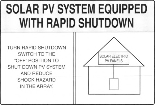
SOLAR PV SYSTEM IS EQUIPPED WITH RAPID SHUTDOWN.
TURN RAPID SHUTDOWN SWITCH TO THE "OFF" POSITION TO SHUT DOWN
PV SYSTEM AND REDUCE SHOCK HAZARD IN ARRAY.
TURN RAPID SHUTDOWN SWITCH TO THE "OFF" POSITION TO SHUT DOWN
PV SYSTEM AND REDUCE SHOCK HAZARD IN ARRAY.
The title "SOLAR PV SYSTEM IS EQUIPPED WITH RAPID SHUTDOWN" shall have these letters capitalized and having a minimum height of 9.5 mm (3/8 in.). All text shall be legible and contrast the background.
Informational Note: See Informational Note Figure 690.12(D).
Informational Note Figure 690.12(D) Label for Roof-Mounted PV Systems with Rapid Shutdown.
(1) Buildings With More Than One Rapid Shutdown Type.
For buildings that have PV systems with more than one rapid shutdown type or PV systems with no rapid shutdown, a detailed plan view diagram of the roof shall be provided showing each different PV system with a dotted line around areas that remain energized after rapid shutdown is initiated.
(2) Rapid Shutdown Switch.
A rapid shutdown switch shall have a label that includes the following wording located on or no more than 1 m (3 ft) from the switch:
RAPID SHUTDOWN SWITCH FOR SOLAR PV SYSTEM
The label shall be reflective, with all letters capitalized and having a minimum height of 9.5 mm (3/8 in.) in white on red background.
690.13 Photovoltaic System Disconnecting Means.
Means shall be provided to disconnect the PV system from all wiring systems including power systems, energy storage systems, and utilization equipment and its associated premises wiring.
(A) Location.
(2) Enclosure Doors and Covers.
Where a disconnecting means for circuits operating above 30 volts is readily accessible to unqualified persons, an enclosure door or hinged cover that exposes energized parts when open shall have its door or cover locked or require a tool to be opened.
(B) Marking.
Each PV system disconnecting means shall plainly indicate whether in the open (off) or closed (on) position and be permanently marked "PV SYSTEM DISCONNECT" or equivalent. Additional markings shall be permitted based upon the specific system configuration. For PV system disconnecting means where the line and load terminals may be energized in the open position, the device shall be marked with the following words or equivalent:
WARNING
ELECTRIC SHOCK HAZARD TERMINALS ON THE LINE AND LOAD SIDES MAY BE ENERGIZED IN THE OPEN POSITION.
The warning sign(s) or label(s) shall comply with 110.21 (B).
(C) Maximum Number of Disconnects.
Each PV system disconnecting means shall consist of not more than six switches or six sets of circuit breakers, or a combination of not more than six switches and sets of circuit breakers, mounted in a single enclosure, or in a group of separate enclosures. A single PV system disconnecting means shall be permitted for the combined ac output of one or more inverters or ac modules.
Informational Note: This requirement does not limit the number of PV systems connected to a service as permitted in 690.4(D). This requirement allows up to six disconnecting means to disconnect a single PV system. For PV systems where all power is converted through interactive inverters, a dedicated circuit breaker, in 705.12(B)(1), is an example of a single PV system disconnecting means.
(D) Ratings.
The PV system disconnecting means shall have ratings sufficient for the maximum circuit current, available fault current, and voltage that is available at the terminals of the PV system disconnect.
(E) Type of Disconnect.
The PV system disconnecting means shall simultaneously disconnect the PV system conductors that are not solidly grounded from all conductors of other wiring systems. The PV system disconnecting means or its remote operating device or the enclosure providing access to the disconnecting means shall be capable of being locked in accordance with 110.25. The PV system disconnecting means shall be one of the following:
- A manually operable switch or circuit breaker
- A connector meeting the requirements of 690.33(D)(1) or (D)(3)
- A pull-out switch with the required interrupting rating
- A remote-controlled switch or circuit breaker that is operable locally and opens automatically when control power is interrupted
- A device listed or approved for the intended application
Informational Note: Circuit breakers marked "line" and "load" may not be suitable for backfeed or reverse current.
690.15 Disconnecting Means for Isolating Photovoltaic Equipment.
Disconnecting means of the type required in 690.15(A) shall be provided to disconnect ac PV modules, fuses, dc-to-dc converters, inverters, and charge controllers from all conductors that are not solidly grounded.
(A) Type of Disconnecting Means.
Where a disconnect is required to isolate equipment, the disconnecting means shall be one of the following:
- An equipment disconnecting means in accordance with 690.1.5(C)
- An isolating device as part of listed equipment where an interlock or similar means prevents the opening of the isolating device under load
- For circuits with a maximum circuit current of 30 amperes or less, an isolating device in accordance with 690.15(B)
(B) Isolating Device.
An isolating device shall not be required to have an interrupting rating. Where an isolating device is not rated for interrupting the circuit current, it shall be marked "Do Not Disconnect Under Load" or "Not for Current Interrupting." An isolating device shall not be required to simultaneously disconnect all current-carrying conductors of a circuit. The isolating device shall be one of the following:
(C) Equipment Disconnecting Means.
Equipment disconnecting means shall comply with the following:
- Have ratings sufficient for the maximum circuit current, available fault current, and voltage that is available at the terminals.
- Simultaneously disconnect all current-carrying conductors that are not solidly grounded to the circuit to which it is connected.
- Be externally operable without exposing the operator to contact with energized parts and shall indicate whether in the open (off) or closed (on) position. Where not within sight or not within 3 m (10 ft) of the equipment, the disconnecting means or its remote operating device or the enclosure providing access to the disconnecting means shall be capable of being locked in accordance with 110.25.
- Be one of the types in 690.13(E)(1) through (E)(5).
Equipment disconnecting means, other than those complying with 690.33, shall be marked in accordance with the warning in 690.13(B) if the line and load terminals can be energized in the open position.
Informational Note: A common installation practice is to terminate PV source-side dc conductors in the same manner that utility source-side ac conductors are generally connected on the line side of a disconnecting means. This practice is more likely to de-energize load-side terminals, blades, and fuses when the disconnect is in the open position and no energized sources are connected to the load side of the disconnect.
(D) Location and Control.
Isolating devices or equipment disconnecting means shall comply with one or more of the following:
- Located within the equipment
- Located in sight from and readily accessible from the equipment for those to whom access is required
- Lockable in accordance with 110.25
- Provided with remote controls to activate the disconnecting means where the remote controls comply with one of the following:
- The disconnecting means and their controls are located within the same equipment.
- The disconnecting means is lockable in accordance with 110.25, and the location of the controls are marked on the disconnecting means.
690.31 Wiring Methods.
(A) Wiring Systems.
(1) Serviceability.
Where wiring devices with integral enclosures are used, sufficient length of cable shall be provided to facilitate replacement.
(3) Conductor Ampacity.
The ampacity of 105°C (221°F) and 125°C (257°F) conductors shall be permitted to be determined by Table 690.31(A)(3)(1). For ambient temperatures greater than 30°C (86°F), the ampacities of these conductors shall be corrected in accordance with Table 690.31(A)(3)(2).
Table 690.31(A)(3)(1) Ampacities of Insulated Conductors Rated Up To and Including 2000 Volts, 105°C Through 125°C (221°F Through 257°F), Not More Than Three Current-Carrying Conductors in Raceway, Cable, or Earth (Directly Buried), Based on Ambient Temperature of 30°C (86°F).
| AWG | Types | |
|---|---|---|
| PVC, CPE, XLPE 105°C | XLPE, EPDM 125°C | |
| 18 | 15 | 16 |
| 16 | 19 | 20 |
| 14 | 29 | 31 |
| 12 | 36 | 39 |
| 10 | 46 | 50 |
| 8 | 64 | 69 |
| 6 | 81 | 87 |
| 4 | 109 | 118 |
| 3 | 129 | 139 |
| 2 | 143 | 154 |
| 1 | 168 | 181 |
| 1/0 | 193 | 208 |
| 2/0 | 229 | 247 |
| 3/0 | 263 | 284 |
| 4/0 | 301 | 325 |
Table 690.31(A)(3)(2) Correction Factors.
| Ambient Temperature (°C) | Temperature Rating of Conductor | Ambient Temperature (°F) | |
|---|---|---|---|
| 105°C (221°F) | 125°C (257°F) | ||
| 30 | 1 | 1 | 86 |
| 31—35 | 0.97 | 0.97 | 87—95 |
| 36—40 | 0.93 | 0.95 | 96—104 |
| 41—45 | 0.89 | 0.92 | 105—113 |
| 46—50 | 0.86 | 0.89 | 114—122 |
| 51—55 | 0.82 | 0.86 | 123—131 |
| 56—60 | 0.77 | 0.83 | 132—140 |
| 61—65 | 0.73 | 0.79 | 141—149 |
| 66—70 | 0.68 | 0.76 | 150—158 |
| 71—75 | 0.63 | 0.73 | 159—167 |
| 76—80 | 0.58 | 0.69 | 168—176 |
| 81—85 | 0.52 | 0.65 | 177—185 |
| 86—90 | 0.45 | 0.61 | 186—194 |
| 91—95 | 0.37 | 0.56 | 195—203 |
| 96—100 | 0.26 | 0.51 | 204—212 |
| 101—105 | - | 0.46 | 213—221 |
| 106—110 | - | 0.4 | 222—230 |
| 111—115 | - | 0.32 | 231—239 |
| 116—120 | - | 0.23 | 240—248 |
(4) Special Equipment.
In addition to wiring methods included elsewhere in this Code, other wiring systems specifically listed for use in PV systems shall be permitted.
Informational Note: See 110.14(C) for conductor temperature limitations due to termination provisions.
(B) Identification and Grouping.
(1) Conductors of Different Systems.
Where not otherwise allowed in an equipment's listing, PV system dc circuits shall not occupy the same equipment wiring enclosure, cable, or raceway as other non-PV systems or inverter output circuits unless separated from other circuits by a barrier or partition.
Exception: Where all conductors or cables have an insulation rating equal to at least the maximum circuit voltage applied to any conductor within the same wiring method, the following shall be permitted:
(1) Multiconductor jacketed cables for remote control, signaling, or power-limited circuits shall be permitted within the same wiring enclosure, cable, or raceway as PV system dc circuits where all circuits serve the PV system.
(2) Inverter output circuits shall be permitted to occupy the same junction box, pull box, or wireway with PV system dc circuits that are identified and grouped as required by 690.31(B)(2) and (B)(3).
(3) PV system dc circuits utilizing multiconductor jacketed cable or metal-clad cable assemblies or listed wiring harnesses identified for the application shall be permitted to occupy the same wiring method as inverter output circuits and other non-PV systems.
(2) Identification.
PV system dc circuit conductors shall be identified at all termination, connection, and splice points by color coding, marking tape, tagging, or other approved means in accordance with 690.31(B)(2)(a) and (B)(2)(b).
Exception: Where the identification of the conductors is evident by spacing or arrangement, further identification shall not be required.
- Conductors that rely on other than color coding for polarity identification-shall be identified by an approved permanent marking means such as labeling, sleeving, or shrink-tubing that is suitable for the conductor size.
- The permanent marking means for nonsolidly grounded positive conductors shall include imprinted plus signs (+) or the word POSITIVE or POS durably marked on insulation of a color other than green, white, or gray. The permanent marking means for nonsolidly grounded negative conductors shall include imprinted negative signs (-) or the word NEGATIVE or NEG durably marked on insulation of a color other than green, white, gray, or red. Only solidly grounded PV system dc circuit conductors shall be marked in accordance with 200.6.
(3) Grouping.
(C) Cables.
(1) Single-Conductor Cable.
Single-conductor cables shall comply with 690.31 (C)(1)(a) through (C)(1)(c).
-
Exposed cables sized 8 AWG or smaller shall be supported and secured at intervals not to exceed 600 mm (24 in.) by cable ties, straps, hangers, or similar fittings listed and identified for securement and support in outdoor locations. PV wire or cable shall be permitted in all locations where RHW-2 is permitted.PV systems meeting the requirements of 691.4 shall be permitted to have support and securement intervals as defined in the engineered design.
- Exposed cables sized larger than 8 AWG shall be supported and secured at intervals not to exceed 1400 mm (54 in.) by cable ties, straps, hangers, or similar fittings listed and identified for securement and support in outdoor locations.
(2) Cable Tray.
Single-conductor PV wire or cable of all sizes or distributed generation (DG) cable of all sizes, with or without a cable tray rating, shall be permitted in cable trays installed in outdoor locations, provided that the cables are supported at intervals not to exceed 300 mm (12 in.) and secured at intervals not to exceed 1400 mm (54 in.).
Where installed in uncovered cable trays, ampacity of single-conductor PV wire smaller than 1/0 AWG, the adjustment factors for 1/0 AWG single conductor cable in 392.80(A)(2) shall be permitted to be used.
Where single-conductor PV wire smaller than 1/0 AWG is installed in ladder ventilated trough cable trays, the following shall apply:
- All single conductors shall be installed in a single layer.
- Conductors that are bound together to comprise each circuit pair shall be permitted to be installed in other than a single layer.
- The sum of diameters of all single conductor cables shall not exceed the cable tray width.
(3) Multiconductor Jacketed Cables.
Where part of a listed PV assembly, multiconductor jacketed cables shall be installed in accordance with the included instructions. Where not part of a listed assembly, or where not otherwise covered in this Code, multiconductor jacketed cables, including DG cable, shall be installed in accordance with the product listing and shall be permitted in PV systems. These cables shall be installed in accordance with the following:
- In raceways, where on or in buildings other than rooftops
- Where not in raceways, in accordance with the following:
- Marked sunlight resistant in exposed outdoor locations
- Protected or guarded, where subject to physical damage
- Closely follow the surface of support structures
- Secured at intervals not exceeding 1.8 m (6 ft)
- Secured within 600 mm (24 in.) of mating connectors or entering enclosures
- Marked direct burial, where buried in the earth
(4) Flexible Cords and Cables Connected to Tracking PV Arrays.
Flexible cords and flexible cables, where connected to moving parts of tracking PV arrays, shall comply with Article 400 and shall be of a type identified as a hard service cord or portable power cable; they shall be suitable for extra-hard usage, listed for outdoor use, water resistant, and sunlight resistant. Allowable ampacities shall be in accordance with 400.5. Stranded copper PV wire shall be permitted to be connected to moving parts of tracking PV arrays in accordance with the minimum number of strands specified in Table 690.31(C)(4).
Table 690.31(C)(4) Minimum PV Wire Strands.
| PV Wire AWG | Minimum Strands |
|---|---|
| 18 | 17 |
| 16—10 | 19 |
| 8—4 | 49 |
| 2 | 130 |
| 1 AWG—1000 MCM | 259 |
(5) Flexible, Fine-Stranded Cables.
Flexible, fine-stranded cables shall be terminated only with terminals, lugs, devices, or connectors in accordance with 110.14.
(6) Small-Conductor Cables.
Single-conductor cables listed for outdoor use that are sunlight resistant and moisture resistant in sizes 16 AWG and 18 AWG shall be permitted for module interconnections where such cables meet the ampacity requirements of 400.5. Section 310.14 shall be used to determine the cable ampacity adjustment and correction factors.
(D) Direct-Current Circuits on or in Buildings.
Wiring methods on or in buildings shall comply with the installation requirements in 690.31(D)(1) and (D)(2).
(1) Metal Raceways and Enclosures.
Where inside buildings, PV system dc circuits that exceed 30 volts or 8 amperes shall be contained in metal raceways, in Type MC metal-clad cable that complies with 250.118(A)(10)(b) or (A)(10)(c), or in metal enclosures.
Exception: PVHCS installed in accordance with 690.12(B)(2)(1) shall be permitted to be provided with or listed for use with nonmetallic enclosure(s), nonmetallic raceway(s), and cables other than Type MC metal-clad cable(s), at the point of penetration of the surface of the building.
(2) Marking and Labeling.
Unless located and arranged so the purpose is evident, the following wiring methods and enclosures that contain PV system dc circuit conductors shall be marked with the wording PHOTOVOLTAIC POWER SOURCE or SOLAR PV DC CIRCUIT by means of permanently affixed labels or other approved permanent marking:
- Exposed raceways, cable trays, and other wiring methods
- Covers or enclosures of pull boxes and junction boxes
- Conduit bodies in which any of the available conduit openings are unused
The labels or markings shall be visible after installation. All letters shall be capitalized and shall be a minimum height of 9.5 mm (3/8 in.) in white on a red background. Labels shall appear on every section of the wiring system that is separated by enclosures, walls, partitions, ceilings, or floors. Spacing between labels or markings, or between a label and a marking, shall not be more than 3 m (10 ft). Labels required by this section shall be suitable for the environment where they are installed.
(E) Bipolar Photovoltaic Systems.
Where the sum, without consideration of polarity, of the voltages of the two monopole circuits exceeds the rating of the conductors and connected equipment, monopole circuits in a bipolar PV system shall be physically separated, and the electrical output circuits from each monopole circuit shall be installed in separate raceways until connected to the inverter. The disconnecting means and overcurrent protective devices for each monopole circuit output shall be in separate enclosures. All conductors from each separate monopole circuit shall be routed in the same raceway. Solidly grounded bipolar PV systems shall be clearly marked with a permanent, legible warning notice indicating that the disconnection of the grounded conductor(s) may result in overvoltage on the equipment.
Exception: Listed switchgear rated for the maximum voltage between circuits and containing a physical barrier separating the disconnecting means for each monopole circuit shall be permitted to be used instead of disconnecting means in separate enclosures.
(F) Wiring Methods and Mounting Systems.
Roof-mounted PV array mounting systems shall be permitted to be held in place with an approved means other than those required by 110.13 and shall utilize wiring methods that allow any expected movement of the array.
Informational Note: Expected movement of unattached PV arrays is often included in structural calculations.
(G) Over 1000 Volts DC.
Equipment and wiring methods containing PV system dc circuits with a maximum voltage greater than 1000 volts shall comply with the following:
- Shall not be permitted on or in one- and two-family dwellings.
- Shall not be permitted within buildings containing habitable rooms.
- Where installed on the exterior of buildings shall be located less than 3 m (10 ft) above grade. Wiring methods containing PV system dc circuits connected to this equipment shall not be permitted to attach to the building greater than 10 m (33 ft) along the building surface from the equipment.
690.32 Component Interconnections.
Fittings and connectors that are intended to be concealed at the time of on-site assembly, where listed for such use, shall be permitted for on-site interconnection of modules or other array components. Such fittings and connectors shall be equal to the wiring method employed in insulation, temperature rise, and short-circuit current rating, and shall be capable of resisting the effects of the environment in which they are used.
690.33 Mating Connectors.
Mating connectors, other than connectors covered by 690.32, shall comply with 690.33(A) through (D).
(A) Configuration.
The mating connectors shall be polarized and shall have a configuration that is noninterchangeable with receptacles in other electrical systems on the premises.
(B) Guarding.
The mating connectors shall be constructed and installed so as to guard against inadvertent contact with live parts by persons.
(C) Type.
The mating connectors shall be of the latching or locking type. Mating connectors that are readily accessible and that are used in circuits operating at over 30 volts dc or 15 volts ac shall require a tool for opening. Where mating connectors are not of the identical type and brand, they shall be listed and identified for intermatability, as described in the manufacturer's instructions.
(D) Interruption of Circuit.
Mating connectors shall be one of the following:
- Rated for interrupting current without hazard to the operator
- A type that requires the use of a tool to open and marked "Do Not Disconnect Under Load" or "Not for Current Interrupting"
- Supplied as part of listed equipment and used in accordance with instructions provided with the listed connected equipment
Informational Note: Some listed equipment, such as micro-inverters, are evaluated to make use of mating connectors as disconnect devices even though the mating connectors are marked as "Do Not Disconnect Under Load" or "Not for Current Interrupting."
690.34 Access to Boxes.
Junction, pull, and outlet boxes located behind modules or panels shall be so installed that the wiring contained in them can be rendered accessible directly or by displacement of a module(s) or panel(s) secured by removable fasteners and connected by a flexible wiring system.
690.41 PV System DC Circuit Grounding and Protection.
(A) PV System DC Circuit Grounding Configurations.
One or more of the following system configurations shall be employed for PV system dc circuits:
- 2-wire circuits with one functionally grounded conductor
- Bipolar circuits according to 690.7(C) with a functional ground reference (center tap)
- Circuits not isolated from the grounded inverter output circuit
- Ungrounded circuits
- Solidly grounded circuits as permitted in 690.41 (B)
- Circuits protected by equipment listed and identified for the use
(B) DC Ground-Fault Detector-Interrupter (GFDI) Protection.
PV system dc circuits that exceed 30 volts or 8 amperes shall be provided with GFDI protection meeting the requirements of 690.41 (B)(1) and (B)(2) to reduce fire hazards.
Solidly grounded PV source circuits with not more than two modules in parallel and not on or in buildings shall be permitted without GFDI protection.
Informational Note: Not all inverters, charge controllers, or dc-to-dc converters include dc GFDI protection. Equipment that does not have GFDI protection often includes the following statement in the manual: "Warning: This unit is not provided with a GFDI device."
(1) Ground-Fault Detection.
The GFDI device or system shall detect ground fault(s) in the PV system dc circuits, including any functionally grounded conductors, and be listed for providing GFDI protection. For dc-to-dc converters not listed as providing GFDI protection, where required, listed GFDI protection equipment identified for the combination of the dc-to-dc converter and the GFDI device shall be installed to protect the circuit.
(2) Faulted Circuits.
The faulted circuits shall be controlled by one of the following methods:
- The current-carrying conductors of the faulted circuit shall be automatically disconnected.
- The device providing GFDI protection fed by the faulted circuit shall automatically cease to supply power to output circuits and interrupt the faulted PV system dc circuits from the ground reference in a functionally grounded system.
(3) Indication of Faults.
The GFDI protection equipment shall provide indication of ground faults at a readily accessible location.
690.42 Point of PV System DC Circuit Grounding Connection.
(B) Solidly Grounded Circuits.
For solidly grounded PV system dc circuits, the grounding connection shall be made from any single point on the PV dc system to a point in the grounding electrode system in 690.47(A).
690.43 Equipment Grounding and Bonding.
Exposed noncurrent-carrying metal parts of PV module frames, electrical equipment, and conductor enclosures of PV systems shall be connected to an equipment grounding conductor in accordance with 250.134 or 250.136, regardless of voltage. Equipment grounding conductors and devices shall comply with 690.43(A) through (D).
(A) Photovoltaic Module Mounting Systems and Devices.
Devices and systems used for mounting PV modules that are also used for bonding module frames shall be listed, labeled, and identified for bonding PV modules.
(B) Equipment Secured to Grounded Metal Supports.
Devices listed, labeled, and identified for bonding and grounding the metal parts of PV systems shall be permitted to bond the equipment to grounded metal supports. Metallic support structures shall have identified bonding jumpers connected between separate metallic sections or shall be identified for equipment bonding and shall be connected to the equipment grounding conductor.
690.45 Size of Equipment Grounding Conductors.
Equipment grounding conductors for PV system circuits shall be sized in accordance with 250.122. Where no overcurrent protective device is used in the circuit, an assumed overcurrent device rated in accordance with 690.9(B) shall be used when applying Table 250.122.
Increases in equipment grounding conductor size to address voltage drop considerations shall not be required.
690.47 Grounding Electrode System.
(A) Buildings or Structures Supporting a PV System.
A building or structure(s) supporting a PV system shall utilize a grounding electrode system installed in accordance with 690.47(B).
PV array equipment grounding conductors shall be connected to a grounding electrode system in accordance with Part VII of Article 250. This connection shall be in addition to any other equipment grounding conductor requirements in 690.43(C). The PV array equipment grounding conductors shall be sized in accordance with 690.45. For specific PV system grounding configurations permitted in 690.41(A), one of the following conditions shall apply:
- For PV systems that are not solidly grounded, the equipment grounding conductor for the output of the PV system, where connected to associated distribution equipment connected to a grounding electrode system, shall be permitted to be the only connection to ground for the system.
- For solidly grounded PV systems, as permitted in 690.41(A)(5), the grounded conductor shall be connected to a grounding electrode system by means of a grounding electrode conductor sized in accordance with 250.166.
Informational Note: Most PV systems are functionally grounded systems rather than solidly grounded systems as defined in this Code. For functionally grounded PV systems with an interactive inverter output, the ac equipment grounding conductor is connected to associated grounded ac distribution equipment. This connection is most often the connection to ground for ground-fault protection and equipment grounding of the PV array.
(B) Grounding Electrodes and Grounding Electrode Conductors.
Additional grounding electrodes shall be permitted to be installed in accordance with 250.52 and 250.54. Grounding electrodes shall be permitted to be connected directly to the PV module frame(s) or support structure. A grounding electrode conductor shall be sized according to 250.66. A support structure for a ground-mounted PV array shall be permitted to be considered a grounding electrode if it meets the requirements of 250.52. PV arrays mounted to buildings shall be permitted to use the metal structural frame of the building if the requirements of 250.68(C)(2) are met.
690.59 Connection to Other Sources.
PV systems connected to other sources shall be installed in accordance with Parts I and II of Article 705.
690.72 Self-Regulated PV Charge Control.
Article 691
Large-Scale Photovoltaic (PV) Electric Supply Stations
691.1 Scope.
This article covers the installation of large-scale PV electric supply stations not under exclusive utility control. 
Informational Note No. 1: Facilities covered by this article have specific design and safety features unique to large-scale PV facilities outlined in 691.4 and are operated for the sole purpose of providing electric supply to a system operated by a regulated utility for the transfer of electric energy.
Informational Note No. 2: See 90.2(B)(5) for additional information about utility-owned properties not covered under this Code. See ANSI/IEEE C2-2017, National Electrical Safety Code, for additional information on electric supply stations.
Informational Note No. 3: See Informational Note Figure 691.1.
Notes:
- The diagram is for informational purposes only and is not representative of all potential configurations.
- Custom designs occur in each configuration, and some components are optional.
Informational Note Figure 691.1 Identification of Large-Scale PV Electric Supply Station Components.
691.4 Special Requirements for Large-Scale PV Electric Supply Stations.
Large-scale PV electric supply stations shall be accessible only to authorized personnel and comply with the following:
- Electrical circuits and equipment shall be maintained and operated only by qualified persons.Informational Note No. 1: See NFPA 70E-2021, Standard for Electrical Safety in the Workplace, for electrical safety requirements.
- Access to PV electric supply stations shall be restricted in accordance with 110.31. Field-applied hazard markings shall be applied in accordance with 110.21 (B).
- The connection between the PV electric supply station and the system operated by a utility for the transfer of electrical energy shall be through medium- or high-voltage switch gear, substation, switch yard, or similar methods whose sole purpose shall be to interconnect the two systems.
- The electrical loads within the PV electric supply station shall only be used to power auxiliary equipment for the generation of the PV power.
- Large-scale PV electric supply stations shall not be installed on buildings.
- The station shall be monitored from a central command center.
- The station shall have an inverter generating capacity of at least 5000 kW.
Informational Note No. 2: Some individual sites with capacities less than 5000 kW are operated as part of a group of facilities with a total generating capacity exceeding 5000 kW.
691.5 Equipment.
All electrical equipment shall be approved for installation by one of the following:
- Listing and labeling
- Be evaluated for the application and have a field label applied
- Where products complying with 691.5(1) or (2) are not available, by engineering review validating that the electrical equipment is evaluated and tested to relevant standards or industry practice
691.6 Engineered Design.
Documentation of the electrical portion of the engineered design of the electric supply station shall be stamped and provided upon request of the AHJ. Additional stamped independent engineering reports detailing compliance of the design with applicable electrical standards and industry practice shall be provided upon request of the AHJ. The independent engineer shall be a licensed professional electrical engineer retained by the system owner or installer. This documentation shall include details of conformance of the design with Article 690, and any alternative methods to Article 690, or other articles of this Code.
691.7 Conformance of Construction to Engineered Design.
Documentation that the construction of the electric supply station conforms to the electrical engineered design shall be provided upon request of the AHJ. Additional stamped independent engineering reports detailing the construction conforms with this Code, applicable standards and industry practice shall be provided upon request of the AHJ. The independent engineer shall be a licensed professional electrical engineer retained by the system owner or installer. This documentation, where requested, shall be available prior to commercial operation of the station.
691.8 Direct Current Operating Voltage.
For large-scale PV electric supply stations, calculations shall be included in the documentation required in 691.6.
691.9 Disconnecting Means for Isolating Photovoltaic Equipment.
Disconnecting means for equipment shall not be required within sight of equipment and shall be permitted to be located remotely from equipment. The engineered design required by 691.6 shall document disconnection procedures and means of isolating equipment.
Informational Note: See NFPA 70B-2019, Recommended Practice for Electrical Equipment Maintenance, for information on electrical system maintenance. See NFPA 70E-2021, Standard for Electrical Safety in the Workplace, for information on written procedures and conditions of maintenance, including lockout/tagout procedures.
691.10 Fire Mitigation.
PV systems that do not comply with the requirements of 690.11 shall include details of fire mitigation plans to address dc arc-faults in the documentation required in 691.6.
Informational Note: Fire mitigation plans are typically reviewed by the local fire agency and include topics such as access roads within the facility.
691.11 Fence Bonding and Grounding.
Fence grounding requirements and details shall be included in the documentation required in 691.6.
Informational Note: See 250.194 for fence bonding and grounding requirements enclosing substation portions of an electric supply station. Grounding requirements for other portions of electric supply station fencing are assessed based on the presence of overhead conductors, proximity to generation and distribution equipment, and associated step and touch potential.
Article 692
Fuel Cell Systems
692.1 Scope.
This article applies to the installation of fuel cell systems.
Informational Note: Some fuel cell systems can be interactive with other electrical power production sources, are stand-alone, or both. Some fuel cell systems are connected to electric energy storage systems such as batteries. Fuel cell systems can have ac output(s), dc output(s), or both for utilization.
692.4 Installation.
(A) Fuel Cell System.
A fuel cell system shall be permitted to supply a building or other structure in addition to any service(s) of another electricity supply system(s).
(C) System Installation.
The construction and operation of equipment, associated wiring, and interconnections shall be performed only by qualified persons.
Informational Note: See Article 100 for the definition of qualified person.
692.6 Listing Requirement.
The fuel cell system shall be approved for the application in accordance with one of the following:
- Be listed for the application
- Be evaluated for the application and have a field label applied
692.8 Circuit Sizing and Current.
(A) Nameplate Rated Circuit Current.
The nameplate(s) rated circuit current shall be the rated current indicated on the fuel cell nameplate(s).
(B) Conductor Ampacity and Overcurrent Device Ratings.
The ampacity of the feeder circuit conductors from the fuel cell system(s) to the premises wiring system shall not be less than the greater of (1) nameplate(s) rated circuit current or (2) the rating of the fuel cell system(s) overcurrent protective device(s).
(C) Ampacity of Grounded or Neutral Conductor.
If an interactive single-phase, 2-wire fuel cell output(s) is connected to the grounded or neutral conductor and a single ungrounded conductor of a 3-wire system or of a 3-phase, 4-wire, wye-connected system, the maximum unbalanced neutral load current plus the fuel cell system(s) output rating shall not exceed the ampacity of the grounded or neutral conductor.
692.9 Overcurrent Protection.
(A) Circuits and Equipment.
If the fuel cell system is provided with overcurrent protection sufficient to protect the circuit conductors that supply the load, additional circuit overcurrent devices shall not be required. Equipment and conductors connected to more than one electrical source shall be protected.
692.13 All Conductors.
Means shall be provided to disconnect all current-carrying conductors of a fuel cell system power source from all other conductors in a building or other structure.
692.17 Switch or Circuit Breaker.
The disconnecting means for ungrounded conductors shall consist of readily accessible, manually operable switch(es) or circuit breaker(s).
Where all terminals of the disconnecting means may be energized in the open position, a warning sign shall be mounted on or adjacent to the disconnecting means. The sign shall be clearly legible and shall have the following words or equivalent:
DANGER
ELECTRIC SHOCK HAZARD. DO NOT TOUCH TERMINALS. TERMINALS ON BOTH THE LINE AND LOAD
SIDES MAY BE ENERGIZED IN THE OPEN POSITION..
The danger sign(s) or label(s) shall comply with 110.21(B).
692.31 Wiring Systems.
In addition to wiring methods included in Chapter 3 of this Code, wiring methods and fittings specifically listed and identified for use with fuel cell systems shall be permitted.
692.50 Fuel Cell Power Sources.
A marking specifying the fuel cell system, output voltage, output power rating, and continuous output current rating shall be provided at the disconnecting means for the fuel cell power source at an accessible location on the site.
692.51 Fuel Shut-Off.
The location of the manual fuel shut-off valve shall be marked at the location of the primary disconnecting means of the building or circuits supplied.
692.52 Stored Energy.
A fuel cell system that stores electrical energy shall require the following warning sign, or equivalent, at the location of the service disconnecting means of the premises:
WARNING
FUEL CELL POWER SYSTEM CONTAINS ELECTRICAL ENERGY STORAGE DEVICES..
The warning sign(s) or label(s) shall comply with 110.21(B).
692.60 Connection to Other Systems.
Fuel cell systems connected to other sources shall be installed in accordance with Parts I and II of Article 705.
692.61 Transfer Switch.
A transfer switch shall be required in non-grid-interactive systems that use utility grid backup. The transfer switch shall maintain isolation between the electrical production and distribution network and the fuel cell system. The transfer switch shall be permitted to be located externally or internally to the fuel cell system unit. Where the utility service conductors of the structure are connected to the transfer switch, the switch shall comply with Article 230, Part V.
Article 694
Wind Electric Systems
694.1 Scope.
This article applies to wind (turbine) electric systems that consist of one or more wind electric generators and their related alternators, generators, inverters, controllers, and associated equipment. 
Informational Note: Some wind electric systems are interactive with other electric power sources (see Informational Note Figure 694.1). Some systems have ac output and some have dc output. Some systems contain electrical energy storage, such as batteries.
Informational Note Figure 694.1 Identification of Wind Electric System Components - Interactive System.
694.7 Construction and Maintenance.
The construction and maintenance, associated wiring, and interconnections shall be performed only by qualified persons.
Informational Note: See Article 100 for the definition of qualified person.
(A) Wind Electric Systems.
A wind electric system(s) shall be permitted to supply a building or other structure in addition to other sources of supply. These requirements apply to both onshore and offshore installations.
(B) Equipment.
Wind electric systems shall comply with one of the following:
- Be listed
- Be evaluated for the application and have a field label applied
Wind electric systems undergoing evaluation for type certification and listing shall be permitted to be operated in a controlled location with access limited to qualified personnel.
Informational Note: See UL 6141, Standard for Wind Turbines Permitting Entry of Personnel, and UL 6142, Standard for Small Wind Turbine Systems, for further information on wind turbine equipment. Ratings for wind turbines could include limitations on installation locations such as onshore or offshore. Testing is typically performed under supervision of a qualified electrical testing organization.
(C) Diversion Load Controllers.
A wind electric system employing a diversion load controller as the primary means of regulating the speed of a wind turbine rotor shall be equipped with an additional, independent, reliable means to prevent over-speed operation. An interconnected utility service shall not be considered to be a reliable diversion load.
(D) Overvoltage Protection.
A listed surge protective device shall be installed between a wind electric system and any loads served by the premises electrical system. The SPD shall be permitted to be a Type 3 SPD on the circuit serving a wind electric system or a Type 2 SPD located anywhere on the load side of the service disconnect. SPDs shall be installed in accordance with Part II of Article 242.
(E) Receptacles.
A receptacle shall be permitted to be supplied by a wind electric system branch or feeder circuit for maintenance or data acquisition use. Receptacles shall be protected with an overcurrent device with a rating not to exceed the current rating of the receptacle. In addition to the requirements in 210.8, all 125-volt, single-phase, 15- and 20-ampere receptacles installed for maintenance of the wind turbine shall have ground-fault circuit-interrupter protection for personnel.
(F) Poles or Towers Supporting Wind Turbines Used as a Raceway.
A pole or tower shall be permitted to be used as a raceway if approved in accordance with one of the following:
- Be evaluated as part of the listing for the wind turbine
- Be listed for the application
- Be evaluated for the application and have a field label applied
(G) Working Clearances.
Working space shall be provided for electrical cabinets and other electrical equipment in accordance with 110.26(A).
For large wind turbines where service personnel enter the equipment, where conditions of maintenance and supervision ensure that only qualified persons perform the work, working clearances shall be permitted to comply with Table 694.7(G) for systems up to 1000 volts nominal.
Table 694.7(G) Working Spaces.
| Nominal Voltage to Ground | Condition 1 | Condition 2 | Condition 3 |
|---|---|---|---|
| 0—150 | 900 mm (3 ft) | 900 mm (3 ft) | 900 mm (3 ft) |
| 151—1000 | 900 mm (3 ft) | 1.0 m (3 ft 6 in.) | 1.2 m (4 ft) |
694.10 Maximum Voltage.
(A) Wind Turbine Output Circuits.
Wind turbine output circuits on or in one- and two-family dwellings shall be permitted to have a maximum voltage up to 600 volts.
(C) Circuits Over 150 Volts to Ground.
In one- and two-family dwellings, live parts in circuits over 150 volts to ground shall not be accessible to other than qualified persons while energized.
Informational Note: See 110.27 for guarding of live parts and 210.6 for branch circuit voltage limitations.
694.12 Circuit Sizing and Current.
(A) Calculation of Maximum Circuit Current.
The maximum current for a circuit shall be calculated in accordance with 694.12(A)(1) through (A)(3).
(1) Turbine Output Circuit Currents.
The maximum current shall be based on the circuit current of the wind turbine operating at maximum output power.
(3) Stand-Alone Inverter Input Circuit Current.
The maximum input current shall be the stand-alone continuous inverter input current rating of the inverter producing rated power at the lowest input voltage.
(B) Ampacity and Overcurrent Device Ratings.
(1) Continuous Current.
Wind turbine electric system currents shall be considered to be continuous.
(2) Sizing of Conductors and Overcurrent Devices.
Circuit conductors and overcurrent devices shall be sized to carry not less than 125 percent of the maximum current as calculated in 694.12(A). The rating or setting of overcurrent devices shall be permitted in accordance with 240.4(B) and (C).
Exception: Circuits containing an assembly, together with its overcurrent devices, listed for continuous operation at 100 percent of its rating shall be permitted to be used at 100 percent of its rating.
694.15 Overcurrent Protection.
(A) Circuits and Equipment.
Turbine output circuits, inverter output circuits, and storage battery circuit conductors and equipment shall be protected in accordance with 240.4 and 240.5. Circuits connected to more than one electrical source shall have overcurrent devices located so as to provide overcurrent protection from all sources.
Exception: An overcurrent device shall not be required for circuit conductors sized in accordance with 694.12(B) where the maximum current from all sources does not exceed the ampacity of the conductors.
Informational Note: Possible backfeed of current from any source of supply, including a supply through an inverter to the wind turbine output circuit, is a consideration in determining whether overcurrent protection from all sources is provided. Some wind electric systems rely on the turbine output circuit to regulate turbine speed. Inverters may also operate in reverse for turbine startup or speed control.
(B) Power Transformers.
Overcurrent protection for a transformer with sources on each side shall be provided in accordance with 450.3 by considering first one side of the transformer, then the other side of the transformer, as the primary.
Exception: A power transformer with a current rating on the side connected to the inverter output, which is not less than the rated continuous output current rating of the inverter, shall not be required to have overcurrent protection at the inverter.
(C) Direct-Current Rating.
Overcurrent devices, either fuses or circuit breakers, used in any dc portion of a wind electric system shall be listed for use in dc circuits and shall have appropriate voltage, current, and interrupting ratings.
694.20 All Conductors.
Means shall be provided to disconnect all current-carrying conductors of a wind electric power source from all other conductors in a building or other structure. A switch, circuit breaker, or other device, either ac or dc, shall not be installed in a grounded conductor if operation of that switch, circuit breaker, or other device leaves the marked, grounded conductor in an ungrounded and energized state.
Exception: A wind turbine that uses the turbine output circuit for regulating turbine speed shall not require a turbine output circuit disconnecting means.
694.22 Additional Provisions.
(A) Disconnecting Means.
The disconnecting means shall not be required to be suitable for use as service equipment. The disconnecting means for ungrounded conductors shall consist of manually operable switches or circuit breakers complying with all of the following requirements:
- They shall be located where readily accessible.
- They shall be externally operable without exposing the operator to contact with live parts.
- They shall plainly indicate whether in the open or closed position.
- They shall have an interrupting rating sufficient for the nominal circuit voltage and the current that is available at the line terminals of the equipment.
Where all terminals of the disconnecting means are capable of being energized in the open position, a warning sign shall be mounted on or adjacent to the disconnecting means. The sign shall be clearly legible and shall have the following words or equivalent:
WARNING.
ELECTRIC SHOCK HAZARD. DO NOT TOUCH TERMINALS. TERMINALS ON BOTH THE LINE AND LOAD
SIDES MAY BE ENERGIZED IN THE OPEN POSITION..
The warning sign(s) or label(s) shall comply with 110.21 (B).
(B) Equipment.
Equipment such as rectifiers, controllers, output circuit isolating and shorting switches, and over-current devices shall be permitted on the wind turbine side of the disconnecting means.
(C) Requirements for Disconnecting Means.
(1) Location.
The wind electric system disconnecting means shall be installed at a readily accessible location either on or adjacent to the turbine tower, on the outside of a building or structure, or inside at the point of entrance of the wind system conductors.
Exception: Installations that comply with 694.30(C) shall be permitted to have the disconnecting means located remotely from the point of entry of the wind system conductors.
The disconnecting means shall not be installed in bathrooms.
For one-family and two-family dwellings, a disconnecting means or manual shutdown button or switch shall be located at a readily accessible location outside the building.
(2) Marking.
Each turbine system disconnecting means shall be permanently marked to identify it as a wind electric system disconnect.
(4) Maximum Number of Disconnects.
The turbine disconnecting means shall consist of not more than six switches or six circuit breakers mounted in a single enclosure, in a group of separate enclosures, or in or on a switchgear.
(D) Equipment That Is Not Readily Accessible.
Rectifiers, controllers, and inverters shall be permitted to be mounted in nacelles or other exterior areas that are not readily accessible.
694.23 Turbine Shutdown.
(A) Manual Shutdown.
Wind turbines shall be required to have a readily accessible manual shutdown button or switch. Operation of the button or switch shall result in a parked turbine state that shall either stop the turbine rotor or allow limited rotor speed combined with a means to de-energize the turbine output circuit.
Exception: Turbines with a swept area of less than 50 m2 (538 ft2) shall not be required to have a manual shutdown button or switch.
(B) Shutdown Procedure.
The shutdown procedure for a wind turbine shall be defined and permanently posted at the location of a shutdown means and at the location of the turbine controller or disconnect, if the location is different.
694.24 Disconnection of Wind Electric System Equipment.
Means shall be provided to disconnect equipment, such as inverters, batteries, and charge controllers, from all ungrounded conductors of all sources. If the equipment is energized from more than one source, the disconnecting means shall be grouped and identified.
A single disconnecting means in accordance with 694.22 shall be permitted for the combined ac output of one or more inverters.
A shorting switch or plug shall be permitted to be used as an alternative to a disconnect in systems that regulate turbine speed using the turbine output circuit.
Exception: Equipment housed in a turbine nacelle shall not be required to have a disconnecting means.
694.26 Fuses.
Means shall be provided to disconnect a fuse from all sources of supply where the fuse is energized from both directions and is accessible to other than qualified persons. Switches, pullouts, or similar devices that are rated for the application shall be permitted to serve as a means to disconnect fuses from all sources of supply.
694.28 Installation and Service of a Wind Turbine.
Open circuiting, short circuiting, or mechanical brakes shall be used to disable a turbine for installation and service.
Informational Note: Some wind turbines rely on the connection from the alternator to a remote controller for speed regulation. Opening turbine output circuit conductors may cause mechanical damage to a turbine and create excessive voltages that could damage equipment or expose persons to electric shock.
694.30 Permitted Methods.
(A) Wiring Systems.
In addition to wiring methods included in Chapter 3 of this Code, wiring methods and fittings specifically intended listed and identified for use on wind turbines shall be permitted. In readily accessible locations, turbine output circuits that operate at voltages greater than 30 volts shall be installed in raceways.
(B) Flexible Cords and Cables.
Flexible cords and cables, where used to connect the moving parts of turbines or where used for ready removal for maintenance and repair, shall comply with Article 400 and shall be of a type identified as hard service cord or portable power cable, shall be suitable for extra-hard usage, shall be listed for outdoor use, and shall be water resistant. Cables exposed to sunlight shall be sunlight resistant. Flexible, fine-stranded cables shall be terminated only with terminals, lugs, devices, or connectors in accordance with 110.14(A).
(C) Direct-Current Turbine Output Circuits Inside a Building.
Direct-current turbine output circuits installed inside a building or structure shall be enclosed in metal raceways or installed in metal enclosures, or run in Type MC metal-clad cable that complies with 250.118(A)(10), from the point of penetration of the surface of the building or structure to the first readily accessible disconnecting means.
694.40 Equipment Grounding and Bonding.
(A) General.
Exposed non-current-carrying metal parts of towers, turbine nacelles, other equipment, and conductor enclosures shall be grounded and bonded to the premises grounding and bonding system. Attached metal parts, such as turbine blades and tails that are not likely to become energized, shall not be required to be grounded or bonded.
(B) Tower Grounding and Bonding.
(1) Grounding Electrodes and Grounding Electrode Conductors.
A wind turbine tower shall be connected to a grounding electrode system. Where installed in close proximity to galvanized foundation or tower anchor components, galvanized grounding electrodes shall be used.
Informational Note: Copper and copper-clad grounding electrodes, where used in highly conductive soils, can cause electrolytic corrosion of galvanized foundation and tower anchor components.
(3) Tower Connections.
Equipment grounding, bonding, and grounding electrode conductors, where used, shall be connected to metallic towers using listed means. All mechanical elements used to terminate these conductors shall be accessible.
(4) Guy Wires.
Guy wires used to support turbine towers shall not be required to be connected to an equipment grounding conductor or to comply with the requirements of 250.110.
Informational Note: Guy wires supporting grounded towers are unlikely to become energized under normal conditions, but partial lightning currents could flow through guy wires when exposed to a lightning environment. Grounding of metallic guy wires may be required by lightning standards. See NFPA 780-2017, Standard for the Installation of Lightning Protection Systems, for information on lightning protection systems.
695.54 Identification of Power Sources.
Wind turbine systems shall be marked with a plaque or directory installed in accordance with 705.10.
696.56 Instructions for Disabling Turbine.
A plaque shall be installed at or adjacent to the turbine location providing basic instructions for disabling the turbine.
694.62 Installation.
Wind electric systems connected to other sources shall be installed in accordance with Parts I and II of Article 705.
694.66 Operating Voltage Range.
Wind electric systems connected to dedicated branch or feeder circuits shall be permitted to exceed normal voltage operating ranges on these circuits, provided that the voltage at any distribution equipment supplying other loads remains within normal ranges.
Informational Note: Wind turbines might use the electric grid to dump energy from short-term wind gusts. See ANSI C84.1-2006, Voltage Ratings for Electric Power Systems and Equipment (60 Hz), for information on normal operating voltages.
Article 695
Fire Pumps
695.1 Scope.
(A) Covered.
This article covers the installation of the following:
- Electric power sources and interconnecting circuits
- Switching and control equipment dedicated to fire pump drivers
Informational Note: Text that is followed by a reference in brackets has been extracted from NFPA 20-2019, Standard for the Installation of Stationary Pumps for Eire Protection. Only editorial changes were made to the extracted text to make it consistent with this Code.
(B) Not Covered.
This article does not cover the following:
- The performance, maintenance, and acceptance testing of the fire pump system and the internal wiring of the components of the system
- The installation of pressure maintenance (jockey or makeup) pumpsInformational Note No. 1: See Article 430 for the installation of pressure maintenance (jockey or makeup) pumps supplied by the fire pump circuit or another source.
- Transfer equipment upstream of the fire pump transfer switch(es)Informational Note No. 2: See NFPA 20-2019, Standard for the Installation of Stationary Pumps for Fire Protection, for further information.
- Water pumps installed in one- and two-family dwellings and used for fire suppression
Informational Note No. 3: See NFPA 13D-2019, Standard for the Installation of Sprinkler Systems in One- and Two-Family Dwellings and Manufactured Homes, for further information.
695.3 Power Source(s) for Electric Motor-Driven Fire Pumps.
Electric motor-driven fire pumps shall have a reliable source of power.
Informational Note: See NFPA 20-2019, Standard for the Installation of Stationary Pumps for Fire Protection, 9.3.2 and A.9.3.2, for guidance on the determination of power source reliability.
(A) Individual Sources.
Where reliable, and where capable of carrying indefinitely the sum of the locked-rotor current of the fire pump motor(s) and the pressure maintenance pump motor(s) and the full-load current of the associated fire pump accessory equipment when connected to this power supply, the power source for an electric motor driven fire pump shall be one or more of the following.
(1) Electric Utility Service Connection.
A fire pump shall be permitted to be supplied by a separate service, or from a connection located ahead of and not within the same cabinet, enclosure, vertical switchgear section, or vertical switchboard section as the service disconnecting means. The connection shall be located and arranged so as to minimize the possibility of damage by fire from within the premises and from exposing hazards. A tap ahead of the service disconnecting means shall comply with 230.82(5). The service equipment shall comply with the labeling requirements in 230.2 and the location requirements in 230.72(B). [20:9.2.2(1)]
(3) Dedicated Feeder.
A dedicated feeder shall be permitted where it is derived from a service connection as described in 695.3(A)(1). [20:9.2.2(3)]
Informational Note: See NFPA 20-2019, Standard for the Installation of Stationary Pumps for Fire Protection, 9.2.2, for more information on normal power sources. Subsection 9.2.2(3) permits a "dedicated feeder" to be derived from a "dedicated service" disconnecting means. Subsection 9.2.2(5) permits a "dedicated transformer connection" that is supplied directly from a "dedicated service disconnecting means" where the service is not at utilization voltage.
(B) Multiple Sources.
If reliable power cannot be obtained from a source described in 695.3(A), power shall be supplied by one of the following: [20:9.3.2]
(2) Individual Source and On-Site Standby Generator.
An approved combination of one or more of the sources in 695.3(A) and an on-site standby generator complying with 695.3(D). [20:9.3.4]
Exception to 695.3(B)(1) and (B)(2): An alternate source of power shall not be required where a back-up engine-driven fire pump, back-up steam turbine-driven fire pump, or back-up electric motor-driven fire pump with an independent power source in accordance with 695.3(A) or (C) is installed.
(C) Multibuilding Campus-Style Complexes.
If the sources in 695.3(A) are not practicable and the installation is part of a multibuilding campus-style complex, feeder sources shall be permitted if approved by the authority having jurisdiction and installed in accordance with either 695.3(C)(1) and (C)(3) or (C)(2) and (C)(3).
(1) Feeder Sources.
Two or more feeders shall be permitted as more than one power source if such feeders are connected to, or derived from, separate utility services. The connection(s), overcurrent protective device(s), and disconnecting means for such feeders shall meet the requirements of 695.4(B)(1)(b).
(2) Feeder and Alternate Source.
A feeder shall be permitted as a normal power source if an alternate power source independent from the feeder is provided. The connection(s), overcurrent protective device(s), and disconnecting means for such feeders shall meet the requirements of 695.4(B)(1)(b).
(3) Selective Coordination.
Overcurrent protective device(s) shall be selectively coordinated with all supply-side overcurrent protective device(s).
Selective coordination shall be selected by a licensed professional engineer or other qualified persons engaged primarily in the design, installation, or maintenance of electrical systems. The selection shall be documented and made available to those authorized to design, install, maintain, and operate the system.
Exception: Selective coordination shall not be required between two overcurrent devices located in series if no loads are connected in parallel with the downstream device.
(D) On-Site Standby Generator as Alternate Source.
An on-site standby generator(s) used as an alternate source of power shall comply with 695.3(D)(1) through (D)(3). [20:9.6.2.1]
(1) Capacity.
The generator shall have sufficient capacity to allow normal starting and running of the motor(s) driving the fire pump(s) while supplying all other simultaneously operated load(s). [20:9.6.1.1]
Automatic shedding of one or more optional standby loads in order to comply with this capacity requirement shall be permitted.
(E) Arrangement.
All power supplies shall be located and arranged to protect against damage by fire from within the premises and exposing hazards. [20:9.1.4]
Multiple power sources shall be arranged so that a fire at one source does not cause an interruption at the other source.
(F) Transfer of Power.
Transfer of power to the fire pump controller between the individual source and one alternate source shall take place within the pump room. [20:9.6.4]
(G) Power Source Selection.
Selection of power source shall be performed by a transfer switch listed for fire pump service. [20:10.8.1.3.1]
(H) Overcurrent Device Selection.
An instantaneous trip circuit breaker shall be permitted in lieu of the overcurrent devices specified in 695.4(B)(2)(a)(1), provided that it is part of a transfer switch assembly listed for fire pump service that complies with 695.4(B)(2)(a)(2).
695.4 Continuity of Power.
Circuits that supply electric motor-driven fire pumps shall be supervised from inadvertent disconnection as covered in 695.4(A) or (B).
(A) Direct Connection.
The supply conductors shall directly connect the power source to a listed fire pump controller, a listed combination fire pump controller and power transfer switch, or a listed fire pump power transfer switch.
(B) Connection Through Disconnecting Means and Overcurrent Device.
(1) Number of Disconnecting Means.
- Feeder Sources. For systems installed under the provisions of 695.3(C) only, additional disconnecting means and the associated overcurrent protective device(s) shall be permitted.
- On-Site Standby Generator. Where an on-site standby generator is used to supply a fire pump, an additional disconnecting means and an associated overcurrent protective device(s) shall be permitted.
General. A single disconnecting means and associated overcurrent protective device(s) shall be permitted to be installed between the fire pump power source(s) and one of the following: [20:9.2.3].
- A listed fire pump controller
- A listed fire pump power transfer switch
- A listed combination fire pump controller and power transfer switch
(2) Overcurrent Device Selection.
Overcurrent devices shall comply with 695.4(B)(2)(a) or (B)(2)(b).
- Individual Sources. Overcurrent protection for individual sources shall comply with the following:
- Overcurrent protection shall be provided by an assembly listed for fire pump service and complying with the following:
- The overcurrent protective device shall not open within 2 minutes at 600 percent of the full-load current of the fire pump motor(s).
- The overcurrent protective device shall not open with a re-start transient of 24 times the full-load current of the fire pump motor(s).
- The overcurrent protective device shall not open within 10 minutes at 300 percent of the full-load current of the fire pump motor(s).
- The trip point for circuit breakers shall not be field adjustable. [20:9.2.3.4.1]
- On-Site Standby Generators. Overcurrent protective devices between an on-site standby generator and a fire pump controller shall be selected and sized to allow for instantaneous pickup of the full pump room load, but shall not be larger than the value selected to comply with 430.62 to provide short-circuit protection only. [20:9.6.1.1]
Overcurrent protective device(s) shall be rated to carry indefinitely the sum of the locked-rotor current of the largest fire pump motor and the full-load current of all of the other pump motors and accessory equipment. [20:9.2.3.4] Where the locked-rotor current value does not correspond to a standard overcurrent device size, the next standard overcurrent device size shall be used in accordance with 240.6. The requirement to carry the locked-rotor currents indefinitely shall not apply to conductors or devices other than overcurrent devices in the fire pump motor circuit(s)..
Exception: The requirement to carry the locked-rotor currents indefinitely shall not apply to feeder overcurrent protective devices installed in accordance with 695.3(C).
(3) Disconnecting Means.
All disconnecting devices that are unique to the fire pump loads shall comply with items 695.4(B)(3)(a) through (B)(3)(e).
- Features and Location - On-Site Standby Generator. The disconnecting means for an on-site standby generator(s) used as the alternate power source shall be installed in accordance with 700.10(B)(6) for emergency circuits and shall be lockable in the closed position. The provision for locking or adding a lock to the disconnecting means shall be installed on or at the switch or circuit breaker used as the disconnecting means and shall remain in place with or without the lock installed.
- Disconnect Marking. The disconnecting means shall be marked "Fire Pump Disconnecting Means." The letters shall be at least 25 mm (1 in.) in height, and they shall be visible without opening enclosure doors or covers. [20:9.2.3.1 (5)]
- Controller Marking. A placard shall be placed adjacent to the fire pump controller, stating the location of this disconnecting means and the location of the key (if the disconnecting means is locked). [20:9.2.3.2]
-
Supervision. The disconnecting means shall be supervised in the closed position by one of the following methods:
- Central station, proprietary, or remote station signal device
- Local signaling service that causes the sounding of an audible signal at a constantly attended point
- Locking the disconnecting means in the closed position
- Sealing of disconnecting means and approved weekly recorded inspections when the disconnecting means are located within fenced enclosures or in buildings under the control of the owner [20:9.2.3.3]
Features and Location - Normal Power Source. The disconnecting means for the normal power source shall comply with all of the following: [20:9.2.3.1].
- Be identified as suitable for use as service equipment.
- Be lockable in the closed position. The provision for locking or adding a lock to the disconnecting means shall be installed on or at the switch or circuit breaker used as the disconnecting means and shall remain in place with or without the lock installed.
- Not be located within the same enclosure, panelboard, switchboard, switchgear, or motor control center, with or without common bus, that supplies loads other than the fire pump.
-
Be located sufficiently remote from other building or other fire pump source disconnecting means such that inadvertent operation at the same time would be unlikely.Exception to 695.4(B)(3)(a): For a multibuilding campus-style complex(s) installed under the provisions of 695.3(C), only the requirements in 695.4(B)(3)(a)(2) shall apply for normal power source disconnects.
695.5 Transformers.
Where the service or system voltage is different from the utilization voltage of the fire pump motor, transformer(s) protected by disconnecting means and overcurrent protective devices shall be permitted to be installed between the system supply and the fire pump controller in accordance with 695.5(A) and (B), or with (C). Only transformers covered in 695.5(C) shall be permitted to supply loads not directly associated with the fire pump system.
(A) Size.
Where a transformer supplies an electric motor driven fire pump, it shall be rated at a minimum of 125 percent of the sum of the fire pump motor(s) and pressure maintenance pump(s) motor loads, and 100 percent of the associated fire pump accessory equipment supplied by the transformer.
(B) Overcurrent Protection.
The primary overcurrent protective device(s) shall be selected or set to carry indefinitely the sum of the locked-rotor current of the fire pump motor(s) and the pressure maintenance pump motor(s) and the full-load current of the associated fire pump accessory equipment when connected to this power supply. Secondary overcurrent protection shall not be permitted. The requirement to carry the locked-rotor currents indefinitely shall not apply to conductors or devices other than overcurrent devices in the fire pump motor circuit(s).
(C) Feeder Source.
Where a feeder source is provided in accordance with 695.3(C), transformers supplying the fire pump system shall be permitted to supply other loads. All other loads shall be calculated in accordance with Article 220, including demand factors as applicable.
(1) Size.
Transformers shall be rated at a minimum of 125 percent of the sum of the fire pump motor(s) and pressure maintenance pump(s) motor loads, and 100 percent of the remaining load supplied by the transformer.
(2) Overcurrent Protection.
The transformer size, the feeder size, and the overcurrent protective device(s) shall be coordinated such that overcurrent protection is provided for the transformer in accordance with 450.3 and for the feeder in accordance with 215.3, and such that the overcurrent protective device(s) is selected or set to carry indefinitely the sum of the locked-rotor current of the fire pump motor(s), the pressure maintenance pump motor(s), the full-load current of the associated fire pump accessory equipment, and 100 percent of the remaining loads supplied by the transformer. The requirement to carry the locked-rotor currents indefinitely shall not apply to conductors or devices other than overcurrent devices in the fire pump motor circuit(s).
695.6 Power Wiring.
Power circuits and wiring methods shall comply with the requirements in 695.6(A) through (J), and as permitted in 230.90(A), Exception No. 4; 230.94, Exception No. 4; 240.13; 230.208; 240.4(A); and 430.31.
(A) Supply Conductors.
(1) Services and On-Site Power Production Facilities.
Service conductors and conductors supplied by on-site power production facilities shall be physically routed outside a building(s) and shall be installed as service-entrance conductors in accordance with 230.6, 230.9, and Parts III and IV of Article 230. Where supply conductors cannot be physically routed outside of buildings, the conductors shall be permitted to be routed through the building(s) where installed in accordance with 230.6(1) or (2).
Exception: The supply conductors within the fire pump room shall not be required to meet 230.6(1) or (2).
(2) Feeders.
Fire pump supply conductors on the load side of the final disconnecting means and overcurrent device(s) permitted by 695.4(B) or conductors that connect directly to an on-site standby generator shall comply with all of the following:
- Independent Routing. The conductors shall be kept entirely independent of all other wiring.
- Associated Fire Pump Loads. The conductors shall supply only loads that are directly associated with the fire pump system.
- Protection from Potential Damage. The conductors shall be protected from potential damage by fire, structural failure, or operational accident.
-
Inside of a Building. Where routed through a building, the conductors shall be protected from fire for 2 hours using one of the following methods:
- The cable or raceway is encased in a minimum 50 mm (2 in.) of concrete.
-
Informational Note No. 1: See UL 2196, Fire Test for Circuit Integrity of Fire-Resistive Power, Instrumentation, Control and Data Cables, for one method of defining a fire-resistive cable system.Informational Note No. 2: See UL Guide Information for Electrical Circuit Integrity Systems (FHIT) for identifying the system and its installation limitations to maintain a minimum 2-hour fire-resistive rating.Informational Note No. 3: The listing organization provides information for fire-resistive cable systems on proper installation requirements to maintain the fire rating.
- The cable or raceway is protected by a listed electrical circuit protective system.
Informational Note No. 4: See UL 1724, Fire Tests for Electrical Circuit Protective Systems, for one method of defining an electrical circuit protective system.Informational Note No. 5: See UL Guide Information for Electrical Circuit Integrity Systems (FHIT) for identifying the system and its installation limitations to maintain a minimum 2-hour fire-resistive rating.Informational Note No. 6: The listing organization provides information for electrical circuit protective systems on proper installation requirements to maintain the fire rating.
(B) Conductor Size.
(1) Fire Pump Motors and Other Equipment.
(C) Overload Protection.
Power circuits shall not have automatic protection against overloads. Except for protection of transformer primaries provided in 695.5(C)(2), branch-circuit and feeder conductors shall be protected against short circuit only. Where a tap is made to supply a fire pump, the wiring shall be treated as service conductors in accordance with 230.6. The applicable distance and size restrictions in 240.21 shall not apply.
Exception No. 1: Conductors between storage batteries and the engine shall not require overcurrent protection or disconnecting means.
Exception No. 2: For an on-site standby generator(s) rated to produce continuous current in excess of 225 percent of the full-load amperes of the fire pump motor, the conductors between the on-site generator(s) and the combination fire pump transfer switch controller or separately mounted transfer switch shall be installed in accordance with 695.6(A)(2).
The protection provided shall be in accordance with the short-circuit current rating of the combination fire pump transfer switch controller or separately mounted transfer switch.
(D) Pump Wiring.
(1) Wiring Methods.
Wiring from the controller(s) to the pump motor shall be in rigid metal conduit, intermediate metal conduit, electrical metallic tubing, liquidtight flexible metal conduit, or liquidtight flexible nonmetallic conduit LFNC-B, listed Type MC cable with an impervious covering, or Type MI cable. [20:9.4.4.1]
(2) Fittings.
Fittings shall be listed for use in wet locations.
(3) Connections.
Electrical connections at motor terminal boxes shall be made with a listed means of connection. Twist-on, insulation-piercing-type, and soldered wire connectors shall not be used for this purpose. [20: 9.4.4.2, 9.4.4.3]
(E) Loads Supplied by Controllers and Transfer Switches.
A fire pump controller and fire pump power transfer switch, if provided, shall not serve any load other than the fire pump for which it is intended.
(F) Mechanical Protection.
All wiring from engine controllers and batteries shall be protected against physical damage and shall be installed in accordance with the controller and engine manufacturer's instructions.
(G) Ground-Fault Protection of Equipment.
Ground-fault protection of equipment shall not be installed in any fire pump power circuit. [20:9.1.8.1]
(H) Listed Electrical Circuit Protective System to Controller Wiring.
Electrical circuit protective system installation shall comply with any restrictions provided in the listing of the electrical circuit protective system used, and the following also shall apply:
- A junction box shall be installed ahead of the fire pump controller a minimum of 300 mm (12 in.) beyond the fire-rated ceiling, wall, or floor bounding the fire zone.
- Where required by the manufacturer of a listed electrical circuit protective system or by the listing, or as required elsewhere in this Code, the raceway between a junction box and the fire pump controller shall be sealed at the junction box end as required and in accordance with the instructions of the manufacturer. [20:9.8.2]
- Standard wiring between the junction box and the controller shall be permitted. [20:9.8.3]
(I) Junction Boxes.
Where fire pump wiring to or from a fire pump controller is routed through a junction box, the following requirements shall be met:
- The junction box shall be securely mounted. [20:9.7(1)]
- Mounting and installing of a junction box shall not violate the enclosure type rating of the fire pump controller(s). [20:9.7(2)]
- Mounting and installing of a junction box shall not violate the integrity of the fire pump controller(s) and shall not affect the short-circuit current rating of the controller(s).
- As a minimum, a Type 2, drip-proof enclosure (junction box) shall be used where installed in the fire pump room. The enclosure shall be listed to match the fire pump controller enclosure type rating. [20:9.7(4)]
- Terminals, junction blocks, wire connectors, and splices, where used, shall be listed. [20:9.7(5)]
- A fire pump controller or fire pump power transfer switch, where provided, shall not be used as a junction box to supply other equipment, including a pressure maintenance (jockey) pump(s).
(J) Terminations.
Where raceways or cable are terminated at a fire pump controller, the following requirements shall be met:
- Raceway or cable fittings listed and identified for use in wet locations shall be used.
- The type rating of the raceway or cable fittings shall be at least equal to that of the fire pump controller.
- The installation instructions of the manufacturer of the fire pump controller shall be followed.
- Alterations to the fire pump controller, other than raceway or cable terminations as allowed elsewhere in this Code, shall be approved by the authority having jurisdiction.
695.7 Voltage Drop.
(A) Motor Starting.
Unless the requirements of 695.7(B) or (C) are met, the voltage at the fire pump controller line terminals shall not drop more than 15 percent below normal (controller-rated voltage) under motor starting conditions. [20:9.4.1]
(B) Emergency Run.
The requirements of 695.7(A) shall not apply to emergency-run mechanical starting, provided a successful start can be demonstrated on the standby generator system. [20:9.4.2]
(D) Motor Running.
The voltage at the contactor load terminals to which the motor is connected shall not drop more than 5 percent below the voltage rating of the motor when the motor is operating at 115 percent of the full-load current rating of the motor. [20:9.4.4]
695.10 Listed Equipment.
Diesel engine fire pump controllers, electric fire pump controllers, electric motors, fire pump power transfer switches, foam pump controllers, and limited service controllers shall be listed for fire pump service. [20:9.5.1.1, 10.1.2.1, 12.1.3.1]
695.12 Equipment Location.
(A) Controllers and Transfer Switches.
Electric motor-driven fire pump controllers and power transfer switches shall be located as close as practicable to, and within sight of, the motors that they control.
(B) Engine-Drive Controllers.
Engine-drive fire pump controllers shall be located as close as is practical to, and within sight of, the engines that they control.
(C) Storage Batteries.
Storage batteries for fire pump engine drives shall be supported above the floor, secured against displacement, and located where they are not subject to physical damage, flooding with water, excessive temperature, or excessive vibration.
(E) Protection Against Pump Water.
Fire pump controller and power transfer switches shall be located or protected so that they are not damaged by water escaping from pumps or pump connections.
695.14 Control Wiring.
(A) Control Circuit Failures.
External control circuits that extend outside the fire pump room shall be arranged so that failure of any external circuit (open or short circuit) shall not prevent the operation of a pump(s) from all other internal or external means. Breakage, disconnecting, shorting of the wires, or loss of power to these circuits could cause continuous running of the fire pump but shall not prevent the controller(s) from starting the fire pump(s) due to causes other than these external control circuits. All control conductors within the fire pump room that are not fault tolerant shall be protected against physical damage. [20:10.5.2.6, 12.5.2.5]
(B) Sensor Functioning.
No undervoltage, phase-loss, frequency-sensitive, or other sensor(s) shall be installed that automatically or manually prohibits actuation of the motor contactor. [20:10.4.5.6]
Exception: A phase-loss sensor(s) shall be permitted only as a part of a listed fire pump controller.
(C) Remote Device(s).
No remote device(s) shall be installed that will prevent automatic operation of the transfer switch. [20:10.8.1.3]
(D) Engine-Drive Control Wiring.
All wiring between the controller and the diesel engine shall be stranded and sized to continuously carry the charging or control currents as required by the controller manufacturer. Such wiring shall be protected against physical damage. Controller manufacturer's specifications for distance and wire size shall be followed. [20:12.3.5.1]
(F) Generator Control Wiring Methods.
Control conductors installed between the fire pump power transfer switch and the standby generator supplying the fire pump during normal power loss shall be kept entirely independent of all other wiring. The integrity of the generator remote start circuit shall be monitored for broken, disconnected, or shorted wires. Loss of integrity shall start the generator(s).
Informational Note: See NFPA 20-2019, Standard for the Installation of Stationary Pumps for Fire Protection, 3.3.7.2, for more information on fault-tolerant external control circuits.
The control conductors shall be protected to resist potential damage by fire or structural failure. Where routed through a building, the conductors shall be protected from fire for 2 hours using one of the following methods:
- The cable or raceway is encased in a minimum 50 mm (2 in.) of concrete.
- Informational Note No. 1: See UL 2196-2017, Standard for Fire Test for Circuit Integrity of Fire-Resistive Power, Instrumentation, Control and Data Cables, for testing requirements for fire-resistive cables.Informational Note No. 2: The listing organization provides information for fire-resistive cable systems on proper installation requirements to maintain the fire rating.
- The cable or raceway is protected by a listed electrical circuit protective system.
Informational Note No. 3: See UL 1724, Fire Tests for Electrical Circuit Protection Systems, for testing requirements for circuit protective systems.
Informational Note No. 4: Electrical circuit protective systems could include, but are not limited to, thermal barriers or a protective shaft.
Informational Note No. 5: The listing organization provides information for electrical circuit protective systems on proper installation requirements to maintain the fire rating.
695.15 Surge Protection.
A listed surge protective device (SPD) shall be installed in or on the fire pump controller.
Informational Note: See UL 1449-2021, Standard for Surge Protective Devices, for proper application of SPD types.
Exception: Surge-protective devices shall not be required in or on a fire pump controller for diesel fire pumps.